EP4127426B1 - Medienkanalanordnung für eine verbrennungskraftmaschine, verbrennungskraftmaschine mit einer medienkanalanordnung, kraftfahrzeug mit einer verbrennungskraftmaschine und verfahren zur herstellung einer medienkanalanordnung - Google Patents
Medienkanalanordnung für eine verbrennungskraftmaschine, verbrennungskraftmaschine mit einer medienkanalanordnung, kraftfahrzeug mit einer verbrennungskraftmaschine und verfahren zur herstellung einer medienkanalanordnung Download PDFInfo
- Publication number
- EP4127426B1 EP4127426B1 EP21710892.7A EP21710892A EP4127426B1 EP 4127426 B1 EP4127426 B1 EP 4127426B1 EP 21710892 A EP21710892 A EP 21710892A EP 4127426 B1 EP4127426 B1 EP 4127426B1
- Authority
- EP
- European Patent Office
- Prior art keywords
- media
- internal combustion
- combustion engine
- media channel
- channel
- Prior art date
- Legal status (The legal status is an assumption and is not a legal conclusion. Google has not performed a legal analysis and makes no representation as to the accuracy of the status listed.)
- Active
Links
Images

Classifications
-
- F—MECHANICAL ENGINEERING; LIGHTING; HEATING; WEAPONS; BLASTING
- F01—MACHINES OR ENGINES IN GENERAL; ENGINE PLANTS IN GENERAL; STEAM ENGINES
- F01M—LUBRICATING OF MACHINES OR ENGINES IN GENERAL; LUBRICATING INTERNAL COMBUSTION ENGINES; CRANKCASE VENTILATING
- F01M11/00—Component parts, details or accessories, not provided for in, or of interest apart from, groups F01M1/00 - F01M9/00
- F01M11/02—Arrangements of lubricant conduits
-
- B—PERFORMING OPERATIONS; TRANSPORTING
- B29—WORKING OF PLASTICS; WORKING OF SUBSTANCES IN A PLASTIC STATE IN GENERAL
- B29C—SHAPING OR JOINING OF PLASTICS; SHAPING OF MATERIAL IN A PLASTIC STATE, NOT OTHERWISE PROVIDED FOR; AFTER-TREATMENT OF THE SHAPED PRODUCTS, e.g. REPAIRING
- B29C45/00—Injection moulding, i.e. forcing the required volume of moulding material through a nozzle into a closed mould; Apparatus therefor
- B29C45/17—Component parts, details or accessories; Auxiliary operations
- B29C45/1703—Introducing an auxiliary fluid into the mould
- B29C45/1704—Introducing an auxiliary fluid into the mould the fluid being introduced into the interior of the injected material which is still in a molten state, e.g. for producing hollow articles
- B29C45/1711—Introducing an auxiliary fluid into the mould the fluid being introduced into the interior of the injected material which is still in a molten state, e.g. for producing hollow articles and removing excess material from the mould cavity by the introduced fluid, e.g. to an overflow cavity
-
- B—PERFORMING OPERATIONS; TRANSPORTING
- B29—WORKING OF PLASTICS; WORKING OF SUBSTANCES IN A PLASTIC STATE IN GENERAL
- B29C—SHAPING OR JOINING OF PLASTICS; SHAPING OF MATERIAL IN A PLASTIC STATE, NOT OTHERWISE PROVIDED FOR; AFTER-TREATMENT OF THE SHAPED PRODUCTS, e.g. REPAIRING
- B29C45/00—Injection moulding, i.e. forcing the required volume of moulding material through a nozzle into a closed mould; Apparatus therefor
- B29C45/17—Component parts, details or accessories; Auxiliary operations
- B29C45/1703—Introducing an auxiliary fluid into the mould
- B29C45/1704—Introducing an auxiliary fluid into the mould the fluid being introduced into the interior of the injected material which is still in a molten state, e.g. for producing hollow articles
- B29C45/1706—Introducing an auxiliary fluid into the mould the fluid being introduced into the interior of the injected material which is still in a molten state, e.g. for producing hollow articles using particular fluids or fluid generating substances
- B29C2045/1707—Introducing an auxiliary fluid into the mould the fluid being introduced into the interior of the injected material which is still in a molten state, e.g. for producing hollow articles using particular fluids or fluid generating substances using a liquid, e.g. water
-
- B—PERFORMING OPERATIONS; TRANSPORTING
- B29—WORKING OF PLASTICS; WORKING OF SUBSTANCES IN A PLASTIC STATE IN GENERAL
- B29C—SHAPING OR JOINING OF PLASTICS; SHAPING OF MATERIAL IN A PLASTIC STATE, NOT OTHERWISE PROVIDED FOR; AFTER-TREATMENT OF THE SHAPED PRODUCTS, e.g. REPAIRING
- B29C45/00—Injection moulding, i.e. forcing the required volume of moulding material through a nozzle into a closed mould; Apparatus therefor
- B29C45/17—Component parts, details or accessories; Auxiliary operations
- B29C45/1703—Introducing an auxiliary fluid into the mould
- B29C45/1704—Introducing an auxiliary fluid into the mould the fluid being introduced into the interior of the injected material which is still in a molten state, e.g. for producing hollow articles
- B29C2045/1724—Introducing an auxiliary fluid into the mould the fluid being introduced into the interior of the injected material which is still in a molten state, e.g. for producing hollow articles hollows used as conduits
-
- B—PERFORMING OPERATIONS; TRANSPORTING
- B29—WORKING OF PLASTICS; WORKING OF SUBSTANCES IN A PLASTIC STATE IN GENERAL
- B29L—INDEXING SCHEME ASSOCIATED WITH SUBCLASS B29C, RELATING TO PARTICULAR ARTICLES
- B29L2031/00—Other particular articles
- B29L2031/748—Machines or parts thereof not otherwise provided for
- B29L2031/749—Motors
-
- F—MECHANICAL ENGINEERING; LIGHTING; HEATING; WEAPONS; BLASTING
- F01—MACHINES OR ENGINES IN GENERAL; ENGINE PLANTS IN GENERAL; STEAM ENGINES
- F01M—LUBRICATING OF MACHINES OR ENGINES IN GENERAL; LUBRICATING INTERNAL COMBUSTION ENGINES; CRANKCASE VENTILATING
- F01M11/00—Component parts, details or accessories, not provided for in, or of interest apart from, groups F01M1/00 - F01M9/00
- F01M11/02—Arrangements of lubricant conduits
- F01M2011/026—Arrangements of lubricant conduits for lubricating crankshaft bearings
Definitions
- the invention relates to a media channel arrangement for an internal combustion engine, with at least one distribution channel for distributing a medium to various components of the internal combustion engine and with at least one inlet channel which is coupled to the distribution channel via at least one media passage opening. Further aspects of the invention relate to an internal combustion engine with a media channel arrangement and a motor vehicle with an internal combustion engine.
- a multi-cylinder internal combustion engine is known with at least one intake port arranged in the cylinder head for each cylinder, which is connected to an intake housing common to several cylinders.
- a streamlined, rounded component that can be placed in front of the cylinder head is provided as a running-in aid, and the intake housing is sealed from the cylinder head by means of a circumferential seal.
- the streamlined, rounded component that forms the running-in aid and the circumferential seal are designed as a single piece, with a common retaining plate being provided, which with its peripheral area forms the circumferential seal and otherwise the running-in aid by having openings that correspond to the intake ports of the cylinder head, and consists of an annular, strongly curved bead that can be connected to the sharp-edged inlet of the intake ports with a sharp edge, which has an inlet cross-section that is considerably larger than the inlet cross-section of the intake port of the cylinder head.
- the WO 2004/048765 A1 a cast component for an internal combustion engine is to be taken.
- the component is a cylinder crankcase that has at least one guide channel that conducts a fluid medium to a point of use, whereby it is designed in the form of a tube and is cast in when the component is cast.
- the fluid medium is oil and the at least one guide channel is an oil supply line to a crankshaft bearing and/or camshaft bearing to be lubricated as a point of use.
- a system for admitting gas, for example air, into an internal combustion engine, in particular a diesel engine, with several cylinders, a cylinder head and a gas distributor on the cylinder head.
- the system comprises a device for reducing the dispersion of swirl movements, called vortices, from one cylinder to another.
- the object of the present invention is to provide a media channel arrangement, an internal combustion engine and a motor vehicle of the type mentioned at the outset, which can be operated with improved efficiency.
- a first aspect of the invention relates to a media channel arrangement for an internal combustion engine, with at least one distribution channel for distributing a medium to various components of the internal combustion engine and with at least one inlet channel which is coupled to the distribution channel via at least one media passage opening.
- the various components can be, for example, respective crankshaft bearings or a cylinder head of the internal combustion engine, to name just a few examples.
- At least one wall area of the distribution channel opposite the media passage opening is curved at least partially towards the media passage opening.
- the wall area opposite the media passage opening is curved in the direction of the media passage opening.
- At least one second wall region adjacent to the wall region and opposite the media passage opening is curved in the opposite direction to the media passage opening.
- the second wall region is curved in the opposite direction to the media passage opening, i.e. curved away from the media passage opening, so to speak.
- the second wall region can therefore have a second curvature, which can be curved in the opposite direction to the media passage opening.
- the distribution channel has a tapering region with an opening cross-section that tapers in the direction of a channel end spaced apart from the wall region. This is advantageous because the tapering opening cross-section can achieve an improved pressure uniform distribution of the medium flowing within the tapering region.
- the media channel arrangement comprises a plurality of media outlet channels which are spaced apart from one another along the tapering region and can be supplied with the medium via the distributor channel. This is advantageous because, due to the tapering opening cross-section and the media outlet channels distributed along the tapering region, at least approximately equal pressures of the medium can be set in the respective media outlet channels.
- the media channel arrangement is formed at least in part from plastic.
- plastic is particularly lightweight.
- the media channel arrangement is designed as an oil gallery.
- oil as a medium that flows through the media channel arrangement designed as an oil gallery does have a particularly temperature-dependent viscosity, but due to the curved wall area of the distribution channel, a comparatively low-resistance transport of the medium within the media channel arrangement can be achieved even at high viscosity and a correspondingly low temperature of the medium designed as oil.
- the media channel arrangement is particularly suitable for use as an oil gallery.
- a second aspect of the invention relates to an internal combustion engine with a media channel arrangement according to the first aspect of the invention.
- the media channel arrangement contributes to the internal combustion engine being able to be operated with improved efficiency.
- a third aspect of the invention relates to a motor vehicle with an internal combustion engine according to the second aspect of the invention.
- a motor vehicle which comprises an internal combustion engine with a media channel arrangement according to the first aspect of the invention, can be operated with improved efficiency.
- a liquid plastic is filled into a cavity that shapes the media channel arrangement, then a liquid is pressed into the cavity and a portion of the liquid plastic is thereby pressed out of the cavity, whereby the portion of the liquid plastic is separated from the plastic that forms the media channel arrangement and remains in the cavity.
- This method can give the media channel arrangement a particularly streamlined contour.
- the liquid can therefore have a dual function namely, on the one hand, to press the part of the liquid plastic out of the cavity and, on the other hand, to cool the remaining plastic in such a way that it solidifies and, in particular, hardens.
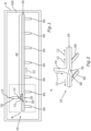
- Fig. 1 shows a highly abstracted representation of a motor vehicle K with an internal combustion engine 100.
- the internal combustion engine comprises a media channel arrangement 10, which in the present case is designed as an oil gallery.
- the media channel arrangement 10 thus serves to guide a medium 12, which is indicated by respective arrows and which in the present case is oil, in particular engine oil.
- the media channel arrangement 10 comprises a distribution channel 20, via which the medium 12 can be guided to various components, which include, for example, crankshaft bearings of the internal combustion engine 100.
- the media channel arrangement 10 comprises a plurality of spaced-apart media outlet channels 60, wherein one of the media outlet channels 60 serves to guide the medium 12 (here: oil) to one of the components.
Landscapes
- Engineering & Computer Science (AREA)
- Mechanical Engineering (AREA)
- Manufacturing & Machinery (AREA)
- General Engineering & Computer Science (AREA)
- Cylinder Crankcases Of Internal Combustion Engines (AREA)
Description
- Die Erfindung betrifft eine Medienkanalanordnung für eine Verbrennungskraftmaschine, mit zumindest einem Verteilerkanal, zum Verteilen eines Mediums an verschiedene Komponenten der Verbrennungskraftmaschine und mit wenigstens einem Zulaufkanal, welcher über zumindest eine Mediendurchgangsöffnung mit dem Verteilerkanal gekoppelt ist. Weitere Aspekte der Erfindung betreffen eine Verbrennungskraftmaschine mit einer Medienkanalanordnung sowie ein Kraftfahrzeug mit einer Verbrennungskraftmaschine.
- Aus der
EP 0 484 312 A1 ist eine Mehrzylinder-Brennkraftmaschine mit je Zylinder mindestens einem im Zylinderkopf angeordneten Einlasskanal bekannt, der an ein für mehrere Zylinder gemeinsames Ansauggehäuse angeschlossen ist. Am scharfkantigen Eintritt der Einlasskanäle in den Zylinderkopf ist je ein dem Zylinderkopf vorsetzbarer strömungsgünstig abgerundetes Bauteil als Einlaufhilfe vorgesehen ist und das Ansauggehäuse gegenüber dem Zylinderkopf mittels einer umlaufenden Dichtung abgedichtet ist. Der die Einlaufhilfe bildende strömungsgünstig abgerundete Bauteil und die umlaufenden Dichtung sind einstückig ausgebildet, wobei eine gemeinsame Halteplatte vorgesehen ist, die mit ihrem Umfangsbereich die umlaufende Dichtung und im Übrigen die Einlaufhilfe bildet, indem sie mit den Einlasskanälen des Zylinderkopfs korrespondierende Öffnungen aufweist, und aus je einem an den scharfkantigen Eintritt der Einlasskanäle mit einer scharfen Kante anschließbaren ringförmigen, stark gewölbten Wulst besteht, der einen Einlaufquerschnitt besitzt, der erheblich größer ist als der Einlassquerschnitt des Einlasskanals des Zylinderkopfes. - Der
WO 2004/048765 A1 ist ein gegossenes Bauteil für eine Brennkraftmaschine zu entnehmen. Bei dem Bauteil handelt es sich um ein Zylinderkurbelgehäuse, das mindestens einen Führungskanal aufweist, der ein fluides Medium zu einer Bedarfsstelle weiterleitet, wobei er in Form eines Rohres ausgebildet und beim Gießen des Bauteiles mit eingegossen ist. Bei dem fluiden Medium handelt es sich um Öl und bei dem mindestens einen Führungskanal um eine Ölzuleitung zu einem zu schmierenden Kurbelwellenlager und/oder Nockenwellenlager als Bedarfsstelle. - Aus der
FR 2 905 141 A1 - Um einen möglichst hohen Wirkungsgrad beim Betrieb einer Verbrennungskraftmaschine zu erzielen, werden verschiedene Ansätze verfolgt. Hierzu gehören beispielsweise Maßnahmen zur Verringerung einer beim Betrieb der Verbrennungskraftmaschine auftretenden Reibleistung sowie ein bedarfsgerechtes Einstellen von Nebenaggregaten, wie beispielsweise einer Ölpumpe, um nur einige Beispiele zu nennen.
- Aufgabe der vorliegenden Erfindung ist es, eine Medienkanalanordnung, eine Verbrennungskraftmaschine sowie ein Kraftfahrzeug der eingangs genannten Art zu schaffen, welche mit verbessertem Wirkungsgrad betrieben werden können.
- Diese Aufgaben werden durch eine Medienkanalanordnung mit den Merkmalen des Patentanspruchs 1, durch eine Verbrennungskraftmaschine mit den Merkmalen des Patentanspruchs 6 sowie durch ein Kraftfahrzeug mit den Merkmalen des Patentanspruchs 7 gelöst. Vorteilhafte Ausgestaltungen mit zweckmäßigen Weiterbildungen der Erfindung sind in den Unteransprüchen angegeben.
- Ein erster Aspekt der Erfindung betrifft eine Medienkanalanordnung für eine Verbrennungskraftmaschine, mit zumindest einem Verteilerkanal, zum Verteilen eines Mediums an verschiedene Komponenten der Verbrennungskraftmaschine und mit wenigstens einem Zulaufkanal, welcher über zumindest eine Mediendurchgangsöffnung mit dem Verteilerkanal gekoppelt ist. Die verschiedenen Komponenten können beispielsweise jeweilige Kurbelwellenlager oder ein Zylinderkopf der Verbrennungskraftmaschine sein, um nur einige Beispiele zu nennen.
- Zudem ist vorgesehen, dass wenigstens ein der Mediendurchgangsöffnung gegenüberliegender Wandbereich des Verteilerkanals zumindest bereichsweise zur Mediendurchgangsöffnung hin gewölbt ist. Mit anderen Worten ist also der Wandbereich, welcher der Mediendurchgangsöffnung gegenüber liegt in Richtung der Mediendurchgangsöffnung gewölbt. Dies ist von Vorteil, da durch eine derartige Wölbung des Wandbereichs in Richtung der Mediendurchgangsöffnung wirksam vermieden werden kann, dass aus dem Zulaufkanal über die Mediendurchgangsöffnung in den Verteilerkanal einströmendes Medium nahezu senkrecht auf den Wandbereich auftrifft, wodurch es zu erhöhten Druckverlusten und Strömungswiderständen bei einem Überströmen des Mediums aus dem Zulaufkanal in den Verteilerkanal kommen würde. Stattdessen kann anhand des in Richtung der Mediendurchgangsöffnung gewölbten Wandbereichs eine besonders strömungsgünstige und dementsprechend druckverlustarme Umlenkung des Mediums innerhalb des Verteilerkanals erfolgen, wodurch im Vergleich zu konventionellen Kanalanordnungen letztlich eine Wirkungsgradverbesserung erzielt werden kann.
- Gemäß der Erfindung ist vorgesehen, dass zumindest ein an den Wandbereich angrenzender, der Mediendurchgangsöffnung gegenüberliegender zweiter Wandbereich entgegengesetzt zur Mediendurchgangsöffnung gewölbt ist. Mit anderen Worten ist also der zweite Wandbereich in zur Mediendurchgangsöffnung entgegengesetzter Richtung gewölbt, also sozusagen von der Mediendurchgangsöffnung weg gewölbt. Der zweite Wandbereich kann also eine zweite Wölbung aufweisen, welche in zur Mediendurchgangsöffnung entgegengesetzten Richtung gewölbt sein kann. Dies ist von Vorteil, da der Wandbereich und der zweite Wandbereich somit gemeinsam einen wellenförmigen Wandabschnitt des Verteilerkanals bilden können, wobei der wellenförmige Wandabschnitt eine besonders strömungsgünstige Führung des Mediums bewirken kann.
- In einer vorteilhaften Weiterbildung der Erfindung ist vorgesehen, dass der Verteilerkanal einen Verjüngungsbereich mit einem sich in Richtung eines von dem Wandbereich beabstandeten Kanalendes verjüngenden Öffnungsquerschnitt aufweist. Dies ist von Vorteil, da durch den sich verjüngenden Öffnungsquerschnitt eine verbesserte Druckgleichverteilung des innerhalb des Verjüngungsbereichs strömenden Mediums erzielt werden kann.
- Eine weitere vorteilhafte Weiterbildung der Erfindung sieht vor, dass die Medienkanalanordnung eine Mehrzahl an Medienablaufkanälen umfasst, welche voneinander beabstandet entlang des Verjüngungsbereichs verteilt und über den Verteilerkanal mit dem Medium versorgbar sind. Dies ist von Vorteil, da aufgrund des sich verjüngenden Öffnungsquerschnitts und der entlang des Verjüngungsbereichs verteilten Medienablaufkanäle zumindest jeweils annähernd gleiche Drücke des Mediums in den jeweiligen Medienablaufkanälen eingestellt werden können.
- Gemäß einer weiteren vorteilhaften Weiterbildung der Erfindung ist die Medienkanalanordnung zumindest bereichsweise aus Kunststoff gebildet. Dies ist von Vorteil, da die zumindest bereichsweise, vorzugsweise vollständig aus Kunststoff gebildete Medienkanalanordnung dadurch - im Gegensatz zu einer etwaigen Ausgestaltung der Medienkanalanordnung aus Metall - eine besonders gute thermische Isolation bietet, sodass eine starke Temperaturänderung des Mediums bei dessen Strömen durch die Medienkanalanordnung vermieden werden kann. Darüber hinaus weist Kunststoff ein besonders geringes Gewicht auf.
- In einer weiteren vorteilhaften Weiterbildung der Erfindung ist die Medienkanalanordnung als Ölgalerie ausgebildet. Dies ist von Vorteil, da Öl als Medium, welches durch die als Ölgalerie ausgestaltete Medienkanalanordnung strömt, zwar eine besonders temperaturabhängige Viskosität aufweist, jedoch aufgrund des gewölbten Wandbereichs des Verteilerkanals auch bei hoher Viskosität und entsprechend niedriger Temperatur des als Öl ausgebildeten Mediums ein vergleichsweise widerstandsarmer Transport des Mediums innerhalb der Medienkanalanordnung erzielt werden kann. Insofern eignet sich die Medienkanalanordnung besonders für deren Einsatz als Ölgalerie.
- Ein zweiter Aspekt der Erfindung betrifft eine Verbrennungskraftmaschine mit einer Medienkanalanordnung gemäß dem ersten Aspekt der Erfindung. Die Medienkanalanordnung trägt dazu bei, dass die Verbrennungskraftmaschine mit verbessertem Wirkungsgrad betrieben werden kann.
- Ein dritter Aspekt der Erfindung betrifft ein Kraftfahrzeug mit einer Verbrennungskraftmaschine gemäß dem zweiten Aspekt der Erfindung. Ein derartiges Kraftfahrzeug, welches eine Verbrennungskraftmaschine mit einer Medienkanalanordnung gemäß dem ersten Aspekt der Erfindung umfasst, kann mit verbessertem Wirkungsgrad betrieben werden.
- Bei einem Verfahren zur Herstellung einer Medienkanalanordnung wird ein flüssiger Kunststoff in eine für die Medienkanalanordnung formgebende Kavität gefüllt, anschließend eine Flüssigkeit in die Kavität gepresst und dadurch ein Teil des flüssigen Kunststoffs aus der Kavität herausgedrückt, wodurch der Teil des flüssigen Kunststoffs von die Medienkanalanordnung bildendem, in der Kavität verbleibendem Kunststoff getrennt wird. Durch dieses Verfahren kann der Medienkanalanordnung eine besonders strömungsgünstige Kontur verliehen werden. Durch das Herausdrücken des Teils des flüssigen Kunststoffs aus der Kavität anhand der Flüssigkeit können strömungsgünstige Verrundungen, insbesondere Kantenverrundungen, geschaffen werden.
- Infolge des Einpressens der Flüssigkeit kann der in der Kavität verbleibende Kunststoff abgekühlt werden und dadurch erstarren. Die Flüssigkeit kann also eine Doppelfunktion erfüllen, nämlich einerseits den Teil des flüssigen Kunststoffs aus der Kavität herausdrücken und andererseits den verbleibenden Kunststoff derart abkühlen, dass sich dieser verfestigt und insbesondere erstarrt.
- Die in Bezug auf einen der Aspekte vorgestellten bevorzugten Ausführungsformen und deren Vorteile gelten entsprechend für die jeweils anderen Aspekte der Erfindung und umgekehrt.
- Die vorstehend in der Beschreibung genannten Merkmale und Merkmalskombinationen sowie die nachfolgend in der Figurenbeschreibung genannten und/oder in den Figuren alleine gezeigten Merkmale und Merkmalskombinationen sind nicht nur in der jeweils angegebenen Kombination, sondern auch in anderen Kombinationen oder in Alleinstellung verwendbar, ohne den Rahmen der Erfindung zu verlassen.
- Weitere Vorteile, Merkmale und Einzelheiten der Erfindung ergeben sich aus den Ansprüchen, der nachfolgenden Beschreibung bevorzugter Ausführungsformen sowie anhand der Zeichnungen.
- Im Folgenden ist die Erfindung noch einmal anhand eines konkreten Ausführungsbeispiels erläutert. Hierzu zeigt:
- Fig. 1
- eine stark abstrahierte Darstellung eines Kraftfahrzeugs mit einer Verbrennungskraftmaschine, welche eine in einer schematischen Seitenansicht gezeigte Medienkanalanordnung aufweist;
- Fig. 2
- eine vergrößerte Darstellung eines in
Fig. 1 umrandeten Bereichs A der Medienkanalanordnung; und - Fig. 3
- eine schematische Schnittdarstellung der Medienkanalanordnung.
-
Fig. 1 zeigt eine stark abstrahierte Darstellung eines Kraftfahrzeugs K mit einer Verbrennungskraftmaschine 100. - Die Verbrennungskraftmaschine umfasst eine vorliegend als Ölgalerie ausgebildet Medienkanalanordnung 10. Die Medienkanalanordnung 10 dient also zum Führen eines durch jeweilige Pfeile verdeutlichten Mediums 12, bei welchem es sich vorliegend um Öl, insbesondere Motoröl, handelt.
- Die Medienkanalanordnung 10 umfasst einen Verteilerkanal 20, über welchen das Medium 12 an verschiedene Komponenten, zu welchen beispielsweise Kurbelwellenlager der Verbrennungskraftmaschine 100 gehören, geführt werden kann. Hierzu umfasst die Medienkanalanordnung 10 eine Mehrzahl an voneinander beabstandeten Medienablaufkanälen 60, wobei jeweils einer der Medienablaufkanäle 60 zum Führen des Mediums 12 (hier: Öl) zu jeweils einer der Komponente dient.
- Die Medienkanalanordnung 10 umfasst des Weiteren einen Zulaufkanal 70 welcher über eine Mediendurchgangsöffnung 72 mit dem Verteilerkanal 20 gekoppelt ist. Das Medium 12 kann also durch den Zulaufkanal 70 und über die Mediendurchgangsöffnung 72 in den Verteilerkanal 20 eingeleitet werden. Die Mediendurchgangsöffnung 72 ist in
Fig. 1 durch eine gestrichelte Linie angedeutet. - Ein der Mediendurchgangsöffnung 72 gegenüberliegender Wandbereich 30 des Verteilerkanals 20 ist zur Mediendurchgangsöffnung 72 hin gewölbt, wie besonders deutlich anhand von
Fig. 2 , welche eine vergrößerte Darstellung eines inFig. 1 gestrichelt umrandeten Bereichs A zeigt, erkennbar ist. Mit anderen Worten weist also der Verteilerkanal 20 eine dem Wandbereich 30 zugeordnete und der Mediendurchgangsöffnung 72 zugewandte Wölbung auf, welche auch als erste Wölbung bezeichnet werden kann. - Ein an den Wandbereich 30 angrenzender, der Mediendurchgangsöffnung 72 gegenüberliegender, zweiter Wandbereich 50 ist - im Gegensatz zum (ersten) Wandbereich 30 entgegengesetzt zur Mediendurchgangsöffnung 72 gewölbt. Mit anderen Worten weist also der Verteilerkanal 20 eine, dem zweiten Wandbereich 50 zugeordnete und der Mediendurchgangsöffnung 72 abgewandte Wölbung auf, welche auch als zweite Wölbung bezeichnet werden kann.
- Der Verteilerkanal 20 umfasst zudem einen Verjüngungsbereich 40 mit einem sich in Richtung 22 eines von dem Wandbereich 30 beabstandeten Kanalendes verjüngenden Öffnungsquerschnitt 72 auf. Die Richtung 22 ist dabei durch einen weiteren Pfeil verdeutlicht. Entlang des Verjüngungsbereichs 40 verteilt sind die jeweiligen Medienablaufkanäle 60 angeordnet, welche über den Verteilerkanal 20 mit dem Medium 12 versorgt werden können.
- Die Medienkanalanordnung 10 ist vorliegend vollständig aus Kunststoff 14 gebildet, wobei jeweilige Wandstärken einer aus dem Kunststoff gebildeten Wandung der Medienkanalanordnung 10 anhand von
Fig. 3 erkennbar sind. Zudem ist anhand vonFig. 3 erkennbar, dass die Medienkanalanordnung 10 einen Steigkanal 62 umfasst, welcher über den Verteilerkanal 20 mit dem Medium 12 versorgt werden kann. Über den Steigkanal 62 kann das Medium 12 zu einem nicht weiter gezeigten Zylinderkopf als weitere Komponente der Verbrennungskraftmaschine 100 geführt werden. - Bei einem Verfahren zur Herstellung der Medienkanalanordnung 10 kann zunächst flüssiger Kunststoff in eine vorliegend nicht weiter gezeigte, für die Medienkanalanordnung 10 formgebende Kavität gefüllt werden. Die Kavität kann beispielsweise als Gussbauteil ausgebildet sein. Anschließend wird eine Flüssigkeit, insbesondere Wasser in die Kavität gepresst und dadurch sozusagen in die Kavität eingespritzt. Dadurch wird ein Teil des flüssigen Kunststoffs aus der Kavität verdrängt und damit herausgedrückt, wodurch der Teil des flüssigen Kunststoffs von die Medienkanalanordnung 10 bildendem, in der Kavität verbleibendem Kunststoff 14 getrennt wird. Der verbleibende Kunststoff 14 bildet dabei eine thermisch isolierende Wandung der Medienkanalanordnung 10.
- Zusammenfassend ist mit der vorliegenden Medienkanalanordnung 10 eine besonders strömungswiderstandsarme und damit druckverlustoptimierte Führung des Mediums 12 (hier: Öl) ermöglicht, zumal die Medienkanalanordnung 10 nicht nur mit den entsprechend gewölbten Wandbereichen 30, 50 versehen ist, sondern auch Verrundungen und den Verjüngungsbereich 40 aufweist. Die Kavität kann beispielsweise als Gussbauteil ausgebildet und bereitgestellt werden, in welches der flüssige Kunststoff gefüllt werden kann. Durch das Pressen der Flüssigkeit in die Kavität wird der überschüssige Teil des flüssigen Kunststoffs aus der Kavität verdrängt, wobei der in der Kavität verbleibende Kunststoff 14 thermisch isolierend wirkt.
-
- 10
- Medienkanalanordnung
- 12
- Medium
- 14
- Kunststoff
- 20
- Verteilerkanal
- 22
- Richtung
- 30
- Wandbereich
- 40
- Verjüngungsbereich
- 42
- Öffnungsquerschnitt
- 50
- zweiter Wandbereich
- 60
- Medienablaufkanal
- 62
- Steigkanal
- 70
- Zulaufkanal
- 72
- Mediendurchgangsöffnung
- 100
- Verbrennungskraftmaschine
- K
- Kraftfahrzeug
Claims (7)
- Medienkanalanordnung (10) für eine Verbrennungskraftmaschine (100), mit zumindest einem Verteilerkanal (20), zum Verteilen eines Mediums (12) an verschiedene Komponenten der Verbrennungskraftmaschine (100) und mit wenigstens einem Zulaufkanal (70), welcher über zumindest eine Mediendurchgangsöffnung (72) mit dem Verteilerkanal (20) gekoppelt ist, wobei wenigstens ein der Mediendurchgangsöffnung (72) gegenüberliegender Wandbereich (30) des Verteilerkanals (20) zumindest bereichsweise zur Mediendurchgangsöffnung (72) hin gewölbt ist,
dadurch gekennzeichnet, dass
zumindest ein an den Wandbereich (30) angrenzender, der Mediendurchgangsöffnung (72) gegenüberliegender zweiter Wandbereich (50) entgegengesetzt zur Mediendurchgangsöffnung (72) gewölbt ist. - Medienkanalanordnung (10) nach Anspruch 1,
dadurch gekennzeichnet, dass
der Verteilerkanal (20) einen Verjüngungsbereich (40) mit einem sich in Richtung (22) eines von dem Wandbereich (30) beabstandeten Kanalendes verjüngenden Öffnungsquerschnitt (42) aufweist. - Medienkanalanordnung (10) nach Anspruch 2,
dadurch gekennzeichnet, dass
die Medienkanalanordnung (10) eine Mehrzahl an Medienablaufkanälen (60) umfasst, welche voneinander beabstandet, entlang des Verjüngungsbereichs (40) verteilt und über den Verteilerkanal (20) mit dem Medium (12) versorgbar sind. - Medienkanalanordnung (10) nach einem der vorhergehenden Ansprüche,
dadurch gekennzeichnet, dass
die Medienkanalanordnung (10) zumindest bereichsweise aus Kunststoff (14) gebildet ist. - Medienkanalanordnung (10) nach einem der vorhergehenden Ansprüche,
dadurch gekennzeichnet, dass
die Medienkanalanordnung (10) als Ölgalerie ausgebildet ist. - Verbrennungskraftmaschine (100) mit einer Medienkanalanordnung (10) nach einem der Ansprüche 1 bis 5.
- Kraftfahrzeug (K) mit einer Verbrennungskraftmaschine (100) nach Anspruch 6.
Applications Claiming Priority (2)
| Application Number | Priority Date | Filing Date | Title |
|---|---|---|---|
| DE102020108331.9A DE102020108331A1 (de) | 2020-03-26 | 2020-03-26 | Medienkanalanordnung für eine Verbrennungskraftmaschine, Verbrennungskraftmaschine mit einer Medienkanalanordnung, Kraftfahrzeug mit einer Verbrennungskraftmaschine und Verfahren zur Herstellung einer Medienkanalanordnung |
| PCT/EP2021/055112 WO2021190871A1 (de) | 2020-03-26 | 2021-03-02 | Medienkanalanordnung für eine verbrennungskraftmaschine, verbrennungskraftmaschine mit einer medienkanalanordnung, kraftfahrzeug mit einer verbrennungskraftmaschine und verfahren zur herstellung einer medienkanalanordnung |
Publications (2)
| Publication Number | Publication Date |
|---|---|
| EP4127426A1 EP4127426A1 (de) | 2023-02-08 |
| EP4127426B1 true EP4127426B1 (de) | 2025-02-26 |
Family
ID=74867500
Family Applications (1)
| Application Number | Title | Priority Date | Filing Date |
|---|---|---|---|
| EP21710892.7A Active EP4127426B1 (de) | 2020-03-26 | 2021-03-02 | Medienkanalanordnung für eine verbrennungskraftmaschine, verbrennungskraftmaschine mit einer medienkanalanordnung, kraftfahrzeug mit einer verbrennungskraftmaschine und verfahren zur herstellung einer medienkanalanordnung |
Country Status (5)
| Country | Link |
|---|---|
| US (1) | US11905863B2 (de) |
| EP (1) | EP4127426B1 (de) |
| CN (1) | CN114981523A (de) |
| DE (1) | DE102020108331A1 (de) |
| WO (1) | WO2021190871A1 (de) |
Citations (3)
| Publication number | Priority date | Publication date | Assignee | Title |
|---|---|---|---|---|
| EP0484312B1 (de) * | 1990-11-02 | 1993-12-01 | AVL Gesellschaft für Verbrennungskraftmaschinen und Messtechnik mbH.Prof.Dr.Dr.h.c. Hans List | Luftansauganlage |
| FR2905141A1 (fr) * | 2006-08-24 | 2008-02-29 | Peugeot Citroen Automobiles Sa | Systeme d'admission de gaz dans un moteur a combustion interne, notamment du type diesel |
| DE102017211826B3 (de) * | 2017-07-11 | 2018-12-27 | Continental Automotive Gmbh | Vorrichtung zur Einspritzung von Wasser für eine Verbrennungskraftmaschine |
Family Cites Families (11)
| Publication number | Priority date | Publication date | Assignee | Title |
|---|---|---|---|---|
| DE3561484D1 (en) * | 1984-08-08 | 1988-02-25 | Fischer Ag Georg | Shaped piercing piece consisting of weldable plastics |
| DE10029844B4 (de) * | 2000-06-16 | 2004-04-15 | Dr.Ing.H.C. F. Porsche Ag | Brennkraftmaschine, insbesondere für Motorräder |
| JP3960785B2 (ja) * | 2001-11-30 | 2007-08-15 | 本田技研工業株式会社 | エンジンの潤滑装置 |
| WO2004048765A1 (de) * | 2002-11-26 | 2004-06-10 | Fritz Winter Eisengiesserei Gmbh & Co. Kg | Gegossenes bauteil für eine brennkraftmaschine |
| US7086915B2 (en) * | 2003-01-31 | 2006-08-08 | Suzuki Motor Corporation | Lubricating structure for outboard motors |
| FR2866386A1 (fr) * | 2004-02-13 | 2005-08-19 | Lc Maitre Ind | Dispositif de soupape et gicleur pour le refroidissement des pistons pour moteur a combustion interne equipe d'une telle soupape |
| CN101458159B (zh) * | 2007-12-11 | 2011-11-23 | 中国兵器工业集团第七○研究所 | 柴油机机油油压分配装置 |
| AT507444B1 (de) | 2008-11-14 | 2010-11-15 | Engel Austria Gmbh | Verfahren zur herstellung eines kunststoffteils |
| US10036346B2 (en) | 2015-09-10 | 2018-07-31 | Ford Global Technologies, Llc | Lubrication circuit and method of forming |
| CN206656062U (zh) * | 2017-04-28 | 2017-11-21 | 台州超远机械有限公司 | 一种用于汽车发动机上的三通接头 |
| CN109825015A (zh) * | 2019-03-26 | 2019-05-31 | 段瑶瑶 | 一种低膨胀系数的聚四氟乙烯塑料管材及其制备方法 |
-
2020
- 2020-03-26 DE DE102020108331.9A patent/DE102020108331A1/de active Pending
-
2021
- 2021-03-02 US US17/793,445 patent/US11905863B2/en active Active
- 2021-03-02 EP EP21710892.7A patent/EP4127426B1/de active Active
- 2021-03-02 WO PCT/EP2021/055112 patent/WO2021190871A1/de not_active Ceased
- 2021-03-02 CN CN202180009103.2A patent/CN114981523A/zh active Pending
Patent Citations (3)
| Publication number | Priority date | Publication date | Assignee | Title |
|---|---|---|---|---|
| EP0484312B1 (de) * | 1990-11-02 | 1993-12-01 | AVL Gesellschaft für Verbrennungskraftmaschinen und Messtechnik mbH.Prof.Dr.Dr.h.c. Hans List | Luftansauganlage |
| FR2905141A1 (fr) * | 2006-08-24 | 2008-02-29 | Peugeot Citroen Automobiles Sa | Systeme d'admission de gaz dans un moteur a combustion interne, notamment du type diesel |
| DE102017211826B3 (de) * | 2017-07-11 | 2018-12-27 | Continental Automotive Gmbh | Vorrichtung zur Einspritzung von Wasser für eine Verbrennungskraftmaschine |
Also Published As
| Publication number | Publication date |
|---|---|
| US11905863B2 (en) | 2024-02-20 |
| CN114981523A (zh) | 2022-08-30 |
| EP4127426A1 (de) | 2023-02-08 |
| WO2021190871A1 (de) | 2021-09-30 |
| DE102020108331A1 (de) | 2021-09-30 |
| US20230044906A1 (en) | 2023-02-09 |
Similar Documents
| Publication | Publication Date | Title |
|---|---|---|
| EP1510681B1 (de) | Zylinderkopfdichtung | |
| DE112020000519T5 (de) | Kombinierte mehrzylindrige hochdruckölpumpe für einen langsam laufenden schiffsmotor | |
| DE102007062347B4 (de) | Kühlanordnung für einen Zylinderkopf einer Brennkraftmaschine | |
| DE102007043992B4 (de) | Ladeluftmodul für eine Verbrennungskraftmaschine | |
| DE3520876C1 (de) | Vorrichtung zum Zuführen von Schmieröl zu den Reibstellen einer Nockenwelle | |
| EP0819837B1 (de) | Kühlkreislauf einer Brennkraftmaschine | |
| EP4127426B1 (de) | Medienkanalanordnung für eine verbrennungskraftmaschine, verbrennungskraftmaschine mit einer medienkanalanordnung, kraftfahrzeug mit einer verbrennungskraftmaschine und verfahren zur herstellung einer medienkanalanordnung | |
| DE10247958A1 (de) | Kraftstoff-Einspritzvorrichtung für eine Brennkraftmaschine | |
| EP2623759A1 (de) | Brennkraftmaschine mit zumindest drei Zylindern | |
| EP2532848B1 (de) | Filter- und Kühlvorrichtung | |
| EP3470714B1 (de) | Ventil zum einstellen eines kühlfluidflusses zur kolbenkühlung | |
| DE19934667B4 (de) | Flüssigkeitsgekühlte Brennkraftmaschine | |
| EP1058782B1 (de) | Ansaugvorrichtung für eine brennkraftmaschine | |
| DE102017212645B4 (de) | Zylinderkopf für eine Verbrennungskraftmaschine | |
| DE102013012496A1 (de) | Kraffstoffinjektor | |
| DE102011114305A1 (de) | Brennkraftmaschine sowie Verfahren zum Betreiben einer Brennkraftmaschine | |
| DE102005025904A1 (de) | Abgasrückführsystem und Verfahren zur Abgasrückführung | |
| DE102021207273A1 (de) | Sekundärlufteinblasvorrichtung und -system | |
| DE102020111176A1 (de) | Verbrennungskraftmaschine mit einer Kühlvorrichtung zum Kühlen von Zylindern und Kraftfahrzeug mit einer Verbrennungskraftmaschine | |
| DE102010036392A1 (de) | Flüssigkeitsgekühlter Zylinderkopf für eine Brennkraftmaschine | |
| DE112018000178T5 (de) | Eine filterbaugruppe mit einem diffusor | |
| EP3415750B1 (de) | Vorrichtung zur luftführung mit kühlraumentlüftung für einen verbrennungsmotor | |
| DE102013017623A1 (de) | Zylindergehäuse für eine Hubkolben-Verbrennungskraftmaschine | |
| WO2018041552A1 (de) | Zylinderkopf für einen verbrennungsmotor | |
| DE202023100941U1 (de) | Nockenwelle |
Legal Events
| Date | Code | Title | Description |
|---|---|---|---|
| STAA | Information on the status of an ep patent application or granted ep patent |
Free format text: STATUS: UNKNOWN |
|
| STAA | Information on the status of an ep patent application or granted ep patent |
Free format text: STATUS: THE INTERNATIONAL PUBLICATION HAS BEEN MADE |
|
| PUAI | Public reference made under article 153(3) epc to a published international application that has entered the european phase |
Free format text: ORIGINAL CODE: 0009012 |
|
| STAA | Information on the status of an ep patent application or granted ep patent |
Free format text: STATUS: REQUEST FOR EXAMINATION WAS MADE |
|
| 17P | Request for examination filed |
Effective date: 20221004 |
|
| AK | Designated contracting states |
Kind code of ref document: A1 Designated state(s): AL AT BE BG CH CY CZ DE DK EE ES FI FR GB GR HR HU IE IS IT LI LT LU LV MC MK MT NL NO PL PT RO RS SE SI SK SM TR |
|
| P01 | Opt-out of the competence of the unified patent court (upc) registered |
Effective date: 20230502 |
|
| DAV | Request for validation of the european patent (deleted) | ||
| DAX | Request for extension of the european patent (deleted) | ||
| P02 | Opt-out of the competence of the unified patent court (upc) changed |
Effective date: 20230808 |
|
| STAA | Information on the status of an ep patent application or granted ep patent |
Free format text: STATUS: EXAMINATION IS IN PROGRESS |
|
| 17Q | First examination report despatched |
Effective date: 20240606 |
|
| GRAP | Despatch of communication of intention to grant a patent |
Free format text: ORIGINAL CODE: EPIDOSNIGR1 |
|
| STAA | Information on the status of an ep patent application or granted ep patent |
Free format text: STATUS: GRANT OF PATENT IS INTENDED |
|
| INTG | Intention to grant announced |
Effective date: 20241119 |
|
| GRAS | Grant fee paid |
Free format text: ORIGINAL CODE: EPIDOSNIGR3 |
|
| GRAA | (expected) grant |
Free format text: ORIGINAL CODE: 0009210 |
|
| STAA | Information on the status of an ep patent application or granted ep patent |
Free format text: STATUS: THE PATENT HAS BEEN GRANTED |
|
| AK | Designated contracting states |
Kind code of ref document: B1 Designated state(s): AL AT BE BG CH CY CZ DE DK EE ES FI FR GB GR HR HU IE IS IT LI LT LU LV MC MK MT NL NO PL PT RO RS SE SI SK SM TR |
|
| REG | Reference to a national code |
Ref country code: GB Ref legal event code: FG4D Free format text: NOT ENGLISH |
|
| REG | Reference to a national code |
Ref country code: CH Ref legal event code: EP |
|
| REG | Reference to a national code |
Ref country code: DE Ref legal event code: R096 Ref document number: 502021006781 Country of ref document: DE |
|
| REG | Reference to a national code |
Ref country code: IE Ref legal event code: FG4D Free format text: LANGUAGE OF EP DOCUMENT: GERMAN |
|
| PGFP | Annual fee paid to national office [announced via postgrant information from national office to epo] |
Ref country code: DE Payment date: 20250311 Year of fee payment: 5 |
|
| PGFP | Annual fee paid to national office [announced via postgrant information from national office to epo] |
Ref country code: AT Payment date: 20250417 Year of fee payment: 5 |
|
| REG | Reference to a national code |
Ref country code: NL Ref legal event code: MP Effective date: 20250226 |
|
| PG25 | Lapsed in a contracting state [announced via postgrant information from national office to epo] |
Ref country code: RS Free format text: LAPSE BECAUSE OF FAILURE TO SUBMIT A TRANSLATION OF THE DESCRIPTION OR TO PAY THE FEE WITHIN THE PRESCRIBED TIME-LIMIT Effective date: 20250526 |
|
| PG25 | Lapsed in a contracting state [announced via postgrant information from national office to epo] |
Ref country code: FI Free format text: LAPSE BECAUSE OF FAILURE TO SUBMIT A TRANSLATION OF THE DESCRIPTION OR TO PAY THE FEE WITHIN THE PRESCRIBED TIME-LIMIT Effective date: 20250226 |
|
| PG25 | Lapsed in a contracting state [announced via postgrant information from national office to epo] |
Ref country code: PL Free format text: LAPSE BECAUSE OF FAILURE TO SUBMIT A TRANSLATION OF THE DESCRIPTION OR TO PAY THE FEE WITHIN THE PRESCRIBED TIME-LIMIT Effective date: 20250226 |
|
| PG25 | Lapsed in a contracting state [announced via postgrant information from national office to epo] |
Ref country code: ES Free format text: LAPSE BECAUSE OF FAILURE TO SUBMIT A TRANSLATION OF THE DESCRIPTION OR TO PAY THE FEE WITHIN THE PRESCRIBED TIME-LIMIT Effective date: 20250226 |
|
| PGFP | Annual fee paid to national office [announced via postgrant information from national office to epo] |
Ref country code: GB Payment date: 20250407 Year of fee payment: 5 |
|
| REG | Reference to a national code |
Ref country code: LT Ref legal event code: MG9D |
|
| PG25 | Lapsed in a contracting state [announced via postgrant information from national office to epo] |
Ref country code: NO Free format text: LAPSE BECAUSE OF FAILURE TO SUBMIT A TRANSLATION OF THE DESCRIPTION OR TO PAY THE FEE WITHIN THE PRESCRIBED TIME-LIMIT Effective date: 20250526 Ref country code: IS Free format text: LAPSE BECAUSE OF FAILURE TO SUBMIT A TRANSLATION OF THE DESCRIPTION OR TO PAY THE FEE WITHIN THE PRESCRIBED TIME-LIMIT Effective date: 20250626 |
|
| PG25 | Lapsed in a contracting state [announced via postgrant information from national office to epo] |
Ref country code: NL Free format text: LAPSE BECAUSE OF FAILURE TO SUBMIT A TRANSLATION OF THE DESCRIPTION OR TO PAY THE FEE WITHIN THE PRESCRIBED TIME-LIMIT Effective date: 20250226 |
|
| PG25 | Lapsed in a contracting state [announced via postgrant information from national office to epo] |
Ref country code: HR Free format text: LAPSE BECAUSE OF FAILURE TO SUBMIT A TRANSLATION OF THE DESCRIPTION OR TO PAY THE FEE WITHIN THE PRESCRIBED TIME-LIMIT Effective date: 20250226 |
|
| PG25 | Lapsed in a contracting state [announced via postgrant information from national office to epo] |
Ref country code: PT Free format text: LAPSE BECAUSE OF FAILURE TO SUBMIT A TRANSLATION OF THE DESCRIPTION OR TO PAY THE FEE WITHIN THE PRESCRIBED TIME-LIMIT Effective date: 20250626 Ref country code: LV Free format text: LAPSE BECAUSE OF FAILURE TO SUBMIT A TRANSLATION OF THE DESCRIPTION OR TO PAY THE FEE WITHIN THE PRESCRIBED TIME-LIMIT Effective date: 20250226 |
|
| PGFP | Annual fee paid to national office [announced via postgrant information from national office to epo] |
Ref country code: FR Payment date: 20250407 Year of fee payment: 5 |
|
| PG25 | Lapsed in a contracting state [announced via postgrant information from national office to epo] |
Ref country code: GR Free format text: LAPSE BECAUSE OF FAILURE TO SUBMIT A TRANSLATION OF THE DESCRIPTION OR TO PAY THE FEE WITHIN THE PRESCRIBED TIME-LIMIT Effective date: 20250527 Ref country code: BG Free format text: LAPSE BECAUSE OF FAILURE TO SUBMIT A TRANSLATION OF THE DESCRIPTION OR TO PAY THE FEE WITHIN THE PRESCRIBED TIME-LIMIT Effective date: 20250226 |
|
| PG25 | Lapsed in a contracting state [announced via postgrant information from national office to epo] |
Ref country code: SE Free format text: LAPSE BECAUSE OF FAILURE TO SUBMIT A TRANSLATION OF THE DESCRIPTION OR TO PAY THE FEE WITHIN THE PRESCRIBED TIME-LIMIT Effective date: 20250226 |
|
| PG25 | Lapsed in a contracting state [announced via postgrant information from national office to epo] |
Ref country code: SM Free format text: LAPSE BECAUSE OF FAILURE TO SUBMIT A TRANSLATION OF THE DESCRIPTION OR TO PAY THE FEE WITHIN THE PRESCRIBED TIME-LIMIT Effective date: 20250226 |
|
| PG25 | Lapsed in a contracting state [announced via postgrant information from national office to epo] |
Ref country code: DK Free format text: LAPSE BECAUSE OF FAILURE TO SUBMIT A TRANSLATION OF THE DESCRIPTION OR TO PAY THE FEE WITHIN THE PRESCRIBED TIME-LIMIT Effective date: 20250226 |
|
| PGFP | Annual fee paid to national office [announced via postgrant information from national office to epo] |
Ref country code: IT Payment date: 20250630 Year of fee payment: 5 |
|
| PG25 | Lapsed in a contracting state [announced via postgrant information from national office to epo] |
Ref country code: EE Free format text: LAPSE BECAUSE OF FAILURE TO SUBMIT A TRANSLATION OF THE DESCRIPTION OR TO PAY THE FEE WITHIN THE PRESCRIBED TIME-LIMIT Effective date: 20250226 Ref country code: CZ Free format text: LAPSE BECAUSE OF FAILURE TO SUBMIT A TRANSLATION OF THE DESCRIPTION OR TO PAY THE FEE WITHIN THE PRESCRIBED TIME-LIMIT Effective date: 20250226 |
|
| PG25 | Lapsed in a contracting state [announced via postgrant information from national office to epo] |
Ref country code: RO Free format text: LAPSE BECAUSE OF FAILURE TO SUBMIT A TRANSLATION OF THE DESCRIPTION OR TO PAY THE FEE WITHIN THE PRESCRIBED TIME-LIMIT Effective date: 20250226 |
|
| REG | Reference to a national code |
Ref country code: CH Ref legal event code: H13 Free format text: ST27 STATUS EVENT CODE: U-0-0-H10-H13 (AS PROVIDED BY THE NATIONAL OFFICE) Effective date: 20251023 |
|
| PG25 | Lapsed in a contracting state [announced via postgrant information from national office to epo] |
Ref country code: SK Free format text: LAPSE BECAUSE OF FAILURE TO SUBMIT A TRANSLATION OF THE DESCRIPTION OR TO PAY THE FEE WITHIN THE PRESCRIBED TIME-LIMIT Effective date: 20250226 |
|
| PG25 | Lapsed in a contracting state [announced via postgrant information from national office to epo] |
Ref country code: LU Free format text: LAPSE BECAUSE OF NON-PAYMENT OF DUE FEES Effective date: 20250302 |