EP4126522B1 - Verwendung eines feuchtigkeitsreservoirs zur runderneuerung - Google Patents
Verwendung eines feuchtigkeitsreservoirs zur runderneuerung Download PDFInfo
- Publication number
- EP4126522B1 EP4126522B1 EP21774481.2A EP21774481A EP4126522B1 EP 4126522 B1 EP4126522 B1 EP 4126522B1 EP 21774481 A EP21774481 A EP 21774481A EP 4126522 B1 EP4126522 B1 EP 4126522B1
- Authority
- EP
- European Patent Office
- Prior art keywords
- tread
- adhesive
- tire
- circumferential tread
- moisture
- Prior art date
- Legal status (The legal status is an assumption and is not a legal conclusion. Google has not performed a legal analysis and makes no representation as to the accuracy of the status listed.)
- Active
Links
Images

Classifications
-
- B—PERFORMING OPERATIONS; TRANSPORTING
- B29—WORKING OF PLASTICS; WORKING OF SUBSTANCES IN A PLASTIC STATE IN GENERAL
- B29D—PRODUCING PARTICULAR ARTICLES FROM PLASTICS OR FROM SUBSTANCES IN A PLASTIC STATE
- B29D30/00—Producing pneumatic or solid tyres or parts thereof
- B29D30/06—Pneumatic tyres or parts thereof (e.g. produced by casting, moulding, compression moulding, injection moulding, centrifugal casting)
- B29D30/52—Unvulcanised treads, e.g. on used tyres; Retreading
- B29D30/54—Retreading
- B29D30/542—Retreading using envelopes or membranes provided with sealings for curing
-
- B—PERFORMING OPERATIONS; TRANSPORTING
- B29—WORKING OF PLASTICS; WORKING OF SUBSTANCES IN A PLASTIC STATE IN GENERAL
- B29D—PRODUCING PARTICULAR ARTICLES FROM PLASTICS OR FROM SUBSTANCES IN A PLASTIC STATE
- B29D30/00—Producing pneumatic or solid tyres or parts thereof
- B29D30/06—Pneumatic tyres or parts thereof (e.g. produced by casting, moulding, compression moulding, injection moulding, centrifugal casting)
- B29D30/52—Unvulcanised treads, e.g. on used tyres; Retreading
- B29D30/54—Retreading
- B29D30/56—Retreading with prevulcanised tread
-
- B—PERFORMING OPERATIONS; TRANSPORTING
- B29—WORKING OF PLASTICS; WORKING OF SUBSTANCES IN A PLASTIC STATE IN GENERAL
- B29D—PRODUCING PARTICULAR ARTICLES FROM PLASTICS OR FROM SUBSTANCES IN A PLASTIC STATE
- B29D30/00—Producing pneumatic or solid tyres or parts thereof
- B29D30/06—Pneumatic tyres or parts thereof (e.g. produced by casting, moulding, compression moulding, injection moulding, centrifugal casting)
- B29D30/52—Unvulcanised treads, e.g. on used tyres; Retreading
- B29D30/54—Retreading
- B29D2030/544—Applying an intermediate adhesive layer, e.g. cement or cushioning element between carcass and tread
Definitions
- Retreaded tires provide an economical way to gain additional use from tire casings after the original tread or retread has become worn.
- worn tire tread on a used tire is removed to create a buffed, treadless surface about the circumference of the tire casing to which a new layer of tread may be bonded.
- the tire casing is then typically inspected for injuries, some of which may be skived and filled with a repair gum while others may be severe enough to warrant rejection of the casing.
- a layer of cement is applied, followed by a layer of cushion gum may be applied to the back, i.e., the inside surface of a new layer of tread, or alternatively, the layer of cushion gum may be applied directly to the tacky surface on the tire casing.
- the cushion gum is a layer of uncured rubber material.
- the cushion gum and tread may be applied in combination about the circumference of the tire casing to create a retreaded tire assembly for curing.
- a length of tire tread may be wrapped around the tire casing with the cushion gum already applied. The cushion gum may form the bond between the tread and the tire casing during curing.
- New tread for precured retreading applications is typically molded as a single piece with the tread pattern on one side and cement applied to the other side of the tread. Such treads are sometimes referred to a precured tread.
- the casing may be trimmed to fit the width of the precured tread.
- stitching is next performed on the assembly to force air from between the tread strip and casing.
- the overall retreaded tire assembly may be placed within a flexible rubber envelope.
- An airtight seal may be created between the envelope and the beads of the tire.
- the entire envelope tire assembly may be placed within a curing chamber and subjected to a vulcanization process that binds the materials together.
- the invention is defined by claim 1.
- a method of retreading a tire includes the steps of applying a primer to an inner surface of a circumferential tread and applying the primer to an outer surface of a tire casing; applying an adhesive to the primer disposed on the inner surface and the primer disposed on the outer surface; applying the circumferential tread to the tire casing so the inner surface contacts the outer surface and a bondline edge forms circumferentially about the tire casing proximate to a shoulder of the tire casing; and coupling a moisture reservoir to the circumferential tread proximate to the bondline edge.
- a method of retreading a tire includes the steps of applying a primer to an inner surface of a circumferential tread and applying the primer to an outer surface of a tire casing; applying an adhesive to the primer disposed on the outer surface; applying the circumferential tread to the tire casing; coupling a moisture reservoir to the circumferential tread; and enclosing the tire casing, the circumferential tread, and the moisture reservoir in an envelope.
- a method of retreading a tire includes the steps of forming a precured tire tread having a first end and a second end; splicing the first end and the second end to form a circumferential tread having an inner surface and a road-contacting outer surface; applying a primer to the entirety of the inner surface; applying a moisture-curing adhesive to the entirety of the inner surface; applying the circumferential tread to a tire casing so a bondline edge forms circumferentially about the tire casing; enclosing the circumferential tread, the tire casing, and a moisture reservoir within an envelope; positioning the moisture reservoir proximate the bondline edge within the envelope; and vacuuming air out of the envelope to apply a pressure to the circumferential tread in a direction generally toward the tire casing.
- Various embodiments discussed herein provide a method of retreading a tire without using a curing chamber or heating oven.
- the method may include using an adhesive with a curing process facilitated by the presence of moisture, and the method may include positioning a moisture reservoir proximate the adhesive during the curing process.
- Tires are used in various applications and under a variety of circumstances. Some tires may be designed to withstand the forces of a landing aircraft. Some tires may be designed to provide extra grip on surfaces covered in snow and ice. Some tires may be manufactured to be more suited to be repairable and retreaded.
- Retread tires are used in applications ranging from aircraft landing gear to long-haul tractor-trailers. Retread tires are used all over the world, including remote locations where access to conventional equipment required to retread a tire casing, and more specifically a curing chamber required to vulcanize rubber, may not be readily available. As such, there is a need for a method of retreading a tire without the use of a curing chamber. In such an instance, it may be difficult or impossible to reach the curing conditions (e.g., temperature, pressure, humidity, etc.) required for vulcanizing rubber, cement, or cushion gum.
- the curing conditions e.g., temperature, pressure, humidity, etc.
- an adhesive e.g., liquid adhesive, etc.
- the adhesive may be a moisture-curing adhesive that relies on moisture (e.g., water) to cure the adhesive and bind the precured tire tread to the tire casing.
- the tire casing and the precured tire tread may be primed with a primer that is structured to prepare the binding surfaces for acceptance of the adhesive.
- the adhesive may then be applied to one or both of the binding surfaces, and then the precured tire tread may be applied to the tire casing, forming a retreaded tire assembly.
- the moisture reservoir may include a predetermined amount of moisture required for curing the adhesive.
- the moisture reservoir may be a towel, cloth, felt, or similar textile able to absorb the predetermined amount of moisture required for curing the adhesive.
- the towel or cloth may be coupled to the retread tire assembly prior to placing the retread tire assembly in the envelope.
- the towel or cloth may be coupled to the precured tire tread, such as by using fasteners or an adhesive.
- the moisture reservoir may be interposed between the envelope and the retreaded tire assembly after the retreaded tire assembly is placed within the envelope.
- Positioning a moisture reservoir proximate to the edges of a bondline formed between the precured tire tread and the tire casing may decrease the amount of time required to cure the adhesive and thus cure the precured tire tread to the tire casing.
- using an adhesive allows the cold process retreading to be a continuous process instead of a batch process. Because the adhesive can be cured without using a curing chamber - a common bottleneck in the retreading process - tires can be retread continuously, one after another. This also reduces the amount of energy required to retread tires, as curing chambers may require great amount of power to operate. And finally, curing the adhesive using a moisture reservoir enables small-volume retreading operations. For example, it may not be cost-effective to operate a curing chamber to cure a single tire. However, when using a moisture reservoir, a single tire may be retreaded without incurring the losses associated with operating a curing chamber for a single tire.
- Curing chambers may be undesirable or ill-equipped for retreading larger tires, such as those used on earth-moving equipment, construction equipment, and farming equipment.
- precured refers to a material that is cured.
- uncured refers to materials that are in their raw form and have not been cured. For example, curing an uncured material results in a cured or precured material.
- precured tire tread refers to a tire tread or BUILD-UP TM (e.g., precured product having no tread pattern thereon; blank; slick) that is separate from (e.g., not cured to) a tire casing.
- the combination of the precured tread cured to the tire casing forms a tire.
- the precured tire tread may take the form of a strip, oval, circle, ring, or similar shape.
- a precured tire tread may include materials and features such as, but not limited to, studs, reinforcing fabrics, Kevlar, nylon, cords, and similar features and materials.
- retreaded tire assembly refers to a PCT assembly applied to a tire casing with an uncured adhesive interposed between the mating surfaces.
- the retreaded tire assembly may be ready to be positioned within an envelope for curing. Once a retreaded tire assembly has been cured, it becomes a tire.
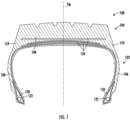
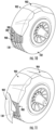
- Figures 1-14 depict an example method of retreading a tire 100 (e.g., an original tire, a new tire, a previously retread or repaired tire, etc.) without the use of a curing chamber (e.g., curing oven, heating oven, etc.).
- the tire 100 includes a tire casing 102 (e.g., tire carcass, etc.) and a tire tread 104.
- the tire 100 is a radial tire; however, the retreading process may be completed on other types of tires, such as bias ply tires.
- the tire 100 includes a pair of side walls 106 bounded by a generally radial outer wall 108 (e.g., crown, etc.) that spans the side walls 106.
- Each of the side walls 106 extend radially inward from outer wall 108 and terminates at a bead area 120, the bead area 120 structured for mounting on a tire rim (not shown).
- the bead area 120 may be designed in a variety of configurations depending on, for example, tire type, tire size, or rim configuration.
- the bead area 120 may also include a bead bundle 122.
- the bead bundle 122 may include, for example, metal strands or wires to improve the strength of the bead area 120.
- the side walls 106 may include multiple layers, such as a rubber layer, a radial ply, and an inner liner which cooperate to provide the strong and flexible side walls 106.
- the side walls 106 are joined to the outer wall 108 and the tire tread 104 through a pair of shoulder areas 124.
- the shoulder areas 124 are contiguous with the side walls 106 and the outer wall 108. In some embodiments, the shoulder areas 124 are contiguous with the tire tread 104.
- the outer wall 108 may be strengthened by a plurality of belts 126 extending circumferentially about the tire casing 102 within the outer wall 108.
- the tire 100 must either be discarded, re-grooved, or retreaded before it should be used on a vehicle for which it was designed.
- cold process retreading what remains of the tire tread 104 is removed from the tire casing 102 by a buffing machine through a buffing operation.
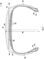
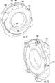
- the tire tread 104 is ground away from the tire casing 102, leaving a buffed tread mounting surface 128 (e.g., mounting surface, mating surface, bonding surface, curing surface, etc.) on the tire casing 102, as shown, for example, in FIG. 2 .
- the mounting surface 128 extends circumferentially about the tire casing 102 and also extends transversely across the outer wall 108 until it terminates at the shoulder areas 124.
- the interface between the mounting surface 128 and the PCT assembly may be referred to as a bondline.
- the bondline may have a width equal to the width of the mounting surface 128.
- the bondline has a width less than the width of the mounting surface 128 as the PCT assembly applied to the tire casing 102 may have a width less than the width of the mounting surface 128
- the bondline extends circumferentially about the tire casing 102 in between the mounting surface 128 and the PCT assembly.
- edges of the bondline 130 may be visible once a PCT assembly has been applied to the tire casing 102.
- the edges of the bondline 130 are defined between the mounting surface 128 and the shoulder areas 124.
- the edges of the bondline 130 may be visible after a PCT assembly has been cured to the tire casing 102.
- the tire 100 includes the edges of the bondline 130, still visible once the tire 100 is applied to a rim of a vehicle.
- the edges of the bondline 130 may be parallel to each other (e.g., concentric, equidistant, etc.) and may extend circumferentially about the tire casing 102.
- the mounting surface 128 defines a diameter, shown as a casing diameter D M . As shown in FIG. 2 , the mounting surface 128 exhibits a curvature between the shoulder areas 124. Thus, the casing diameter D M may be greater proximate a center line C M of the mounting surface 128 when compared to the casing diameter D M proximate the edges of the bondline 130. In some embodiments, the mounting surface 128 is buffed to a slightly rounded (e.g., toroidal) radius extending between the shoulder areas 124. In some embodiments, the mounting surface 128 is flat such that the casing diameter D M is generally the same at all points between the edges of the bondline 130.
- the tire 100 is shown after the buffing operation where the tire tread 104 has been removed.
- a portion of the tire tread 104 may be left behind on the tire 100, such as if the user would like to increase a thickness of the outer wall 108 before applying a PCT assembly to the tire casing 102.
- the tire tread 104 has been removed, leaving behind (e.g., exposing, revealing, etc.) the buffed tread mounting surface 128.
- a process called skiving and filling may be performed on the tire casing 102.
- Skiving is the removal of damaged material or undesired material from the tire casing 102 prior to making a repair or performing a retread operation.
- the tire casing 102 accumulates holes, nicks, punctures, or tears due to stones or other sharp objects the tire 100 comes in contact with during use.
- the injured or damaged area is first ground smooth by an appropriate grinding tool and then filled with repair gum (e.g., uncured rubber material). It is necessary to fill the injured areas to the level of the mounting surface 128 (e.g., such that the tread mounting surface 128 remains smooth) to avoid air pockets between the mounting surface 128 and a later-applied PCT assembly.
- repair gum e.g., uncured rubber material
- Trapped air between the mounting surface 128 and the PCT assembly can have negative effects on the longevity of a typical retreaded tire (e.g., the tire 100).
- a building step occurs in which an adhesive (e.g., cushion gum, polyurethane adhesive, rubber cement, liquid adhesive, etc.) and a PCT assembly are applied to (e.g., wrapped around, placed on, stretched over, disposed about, etc.) the mounting surface 128.
- an adhesive e.g., cushion gum, polyurethane adhesive, rubber cement, liquid adhesive, etc.
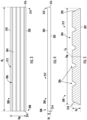
- the PCT assembly 300 may be formed of rubber, natural rubber, synthetic rubber, various polymers, and compounding ingredients, such as such as carbon black, silica, anti-degradants, and zinc oxide, in order to produce the PCT assembly 300 having the desired end properties.
- the PCT assembly 300 may be formed in a strip having a tread width D W corresponding to a width of the mounting surface 128 between the shoulder areas 124.
- the PCT assembly 300 may define a tread length D L corresponding to the casing diameter D M (e.g., the tread length D T may be equal to a circumference of the mounting surface 128,, the tread length D T may be equal to the circumference of the mounting surface 128 proximate the center line C M ). In some embodiments, the PCT assembly 300 is cut to have a tread length slightly less than (e.g., 7,62cm (3 inches) less than) the circumference of the mounting surface 128 such that the PCT assembly 300 may be stretched over the tire casing 102.
- the PCT assembly 300 may further define a tread thickness, shown as a tread thickness D T .
- the PCT assembly 300 may include a mounting surface 302 (e.g., generally planar mounting surface, continuous surface, mating surface, binding surface, etc.) and an opposing surface 304 (e.g., generally planar opposing surface, road-contacting surface, tread surface, etc.).
- the mounting surface 302 may be configured such that the PCT assembly 300 may be applied to the corresponding mounting surface 128 on the tire casing 102. More specifically, the mounting surface 302 may be configured to be cured to the mounting surface 128 to form the tire 100. While the mounting surface 302 is shown as flat in FIGS. 4 and 5 , in some embodiments, the PCT assembly 300 may include a mounting surface that is curved in order to match the curvature of the mounting surface 128.
- the opposing surface 304 may be configured to interface with a road surface and may include a plurality of grooves 306 designed to channel water and provide added traction during certain road and weather conditions.
- the PCT assembly 300 may include a reinforcing fabric layer (e.g., a reinforcing belt, a plurality of reinforcing fabric layers, etc.) positioned within the PCT assembly 300 between the mounting surface 302 and the opposing surface 304.
- the PCT assembly 300 includes a reinforcing fabric layer coupled to and extending over the mounting surface 302, the reinforcing fabric layer structured to prevent foreign bodies (e.g., nails, sharp objects, glass, etc.) from penetrating the mounting surface 128 and damaging the tire casing 102.
- the PCT assembly 300 includes a plurality of air passages (e.g., air channels) positioned across the mounting surface 302.
- the plurality of air passages may facilitate the removal of air from between the PCT assembly 300 and the tire casing 102 during a retreading process of the tire 100 (e.g., the tire casing 102). More specifically, the air passages may facilitate the removal of air from between the mounting surface 302 and the mounting surface 128.
- the PCT assembly 300 may include a first PCT end 308 and a second PCT end 310. Extending between the first PCT end 308 and the second PCT end 310, and positioned on (e.g., profiled along, molded in, cut in, etc.) the opposing surface 304, may be a tread pattern 312 (e.g., a tread design, a series of treads, a tread pattern repetition, etc.).
- the tread pattern 312 may include a plurality of lugs, grooves, cuts, sipes, sipe cuts, and similar features.
- the tread pattern 312 may include the grooves 306.
- the first PCT end 308 may include a first PCT end surface 314.
- the first PCT end surface 314 may be contiguous with both the mounting surface 302 and the opposing surface 304. In some embodiments, the first PCT end surface 314 may be perpendicular to the mounting surface 302.
- the second PCT end 310 may include a second PCT end surface 316.
- the second PCT end surface 316 may be contiguous with both the mounting surface 302 and the opposing surface 304. In some embodiments, the second PCT end surface 316 may be perpendicular to the mounting surface 302.
- the PCT assembly 300 may further include a first PCT side 318 and a second PCT side 320 opposite the first PCT side 318.
- the first PCT side 318 may be parallel to the second PCT side 320.
- the first PCT side 318 and the second PCT side 320 extend away from the mounting surface 302 in a direction generally toward a center line C A of the PCT assembly 300.
- the first PCT side 318 and the second PCT side 320 may be positioned proximate the edges of the bondline 130.
- the interface between the mounting surface 128 and the mounting surface 302 may be referred to as a bondline.
- a portion of the mounting surface 128 may still show (e.g., not be covered by the PCT assembly 300) between the edges of the bondline 130 and the shoulder areas 124.
- the PCT assembly 300 may be formed by extrusion. In some embodiments, the PCT assembly 300 is formed by molding. The PCT assembly 300 may be formed in a mold such that the tread pattern 312 proximate the first PCT end 308 is continued by the tread pattern 312 proximate the second PCT end 310 such that when the first PCT end 308 and the second PCT end 310 are coupled together, the tread pattern 312 is not interrupted by a break, but continues infinitely around a perimeter of the opposing surface 304.
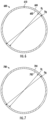
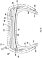
- a precision circumferential tread 600 (e.g., circumferential tread, annular tread, etc.) 600 is shown.
- the precision circumferential tread 600 is similar to the PCT assembly 300.
- a difference between the precision circumferential tread 600 and the PCT assembly 300 is that the precision circumferential tread 600 is formed as a ring (e.g., circle, hoop, cylinder, annular body, etc.).
- the precision circumferential tread 600 is formed from the PCT assembly 300 by coupling (e.g., splicing) the first PCT end 308 to the second PCT end 310 such that the PCT assembly 300 forms a ring.
- the precision circumferential tread 600 may be formed by coupling the first PCT end surface 314 to the second PCT end surface 316.
- the first PCT end 308 and the second PCT end 310 may be hot spliced together (e.g., vulcanized together using unvulcanized rubber (e.g., a cushion gum), such as HD-30).
- the precision circumferential tread 600 defines an inner surface 602 and an outer surface 604.
- the outer surface 604 is similar to the opposing surface 304.
- the outer surface 604 may be configured to interface with a road surface (e.g., asphalt, tarmac, cement, road, etc.) when the precision circumferential tread 600 is cured to the tire casing 102, and the tire 100 is mounted to a vehicle.
- the outer surface 604 may include a tread pattern, such as the tread pattern 312. In some embodiments, the tread pattern 312 may infinitely repeat around a circumference of the precision circumferential tread 600 (e.g., around the outer surface 604).
- the precision circumferential tread 600 further defines an inner diameter D I and an outer diameter D O .
- the precision circumferential tread 600 includes a splice 610.
- the splice 610 is structured to form the inner surface 602 such that the inner surface 602 is circumferentially contiguous (e.g., is smooth, does not include a bump proximate the splice 610).
- the splice 610 is structured to form the outer surface 604 such that the tread pattern 312 is infinitely repeating circumferentially about the circumference of the outer surface 604 (e.g., the tread pattern 312 is not interrupted, the tread pattern 312 has no beginning or end, etc.).
- the splice 610 is structured to form the outer surface 604 such that the tread pattern 312 is discontinuous (e.g., non-repeating) at the splice 610.
- the splice 610 is formed by a hot splicing process between two ends of a PCT assembly.
- the splice 610 couples together the first PCT end 308 and the second PCT end 310. For example, a user may acquire the PCT assembly 300 and hot splice the ends together, forming the precision circumferential tread 600.
- the splice 610 includes a cushion gum (e.g., uncured rubber, rope rubber, etc.) that has been cured using a curing process.
- the cushion gum forming the splice 610 may be HD-30, a cushion gum having a curing temperature of 98°C (210°F degrees Fahrenheit).
- the cushion gum may be applied to (e.g., spread on, stuck to, etc.) the first PCT end 308, and then the first PCT end 308 may be placed in contact with (e.g., coupled to, stuck to) the second PCT end 310.
- the cushion gum may be applied to the first PCT end surface 314 and the second PCT end surface 316, and then the first PCT end surface 314 may be placed in contact with the second PCT end surface 316.
- An inherent tackiness (e.g., stickiness) of the cushion gum may hold the first PCT end 308 and the second PCT end 310 together prior to curing the cushion gum.
- the cushion gum may then be cured using a hot splicing machine.
- the hot splicing machine includes a mold corresponding to the tread pattern 312 and the grooves 306 such that as the cushion gum cures, the cushion gum conforms to the mold and the tread pattern 312 is uninterrupted across the outer surface 604.
- the cushion gum is cut (e.g., using tools, knives, razors, skive, etc.) to match the tread pattern 312 on the outer surface 604 such that the tread pattern 312 is not interrupted.
- the tread pattern 312 is interrupted (e.g., the tread pattern 312 is not infinitely continuous around the perimeter of the precision circumferential tread 600, such as by the splice 610 between the first PCT end 308 and the second PCT end 310.
- first PCT end 308 and the second PCT end 310 may be coupled together using an adhesive, such as a liquid adhesive or a moisture-curable adhesive. More specifically, the first PCT end surface 314 and the second PCT end surface 316 may be bonded using an adhesive to form the precision circumferential tread 600.
- the precision circumferential tread 600 may be formed of rubber. In some embodiments, the precision circumferential tread 600 my exhibit an inherent compliance such that the inner diameter D I may be operable between a relaxed inner diameter (e.g., the inner diameter D I shown in FIG. 6 ) and a stretched inner diameter, where the stretched inner diameter is greater than the relaxed inner diameter D I .
- a relaxed inner diameter e.g., the inner diameter D I shown in FIG. 6
- a stretched inner diameter where the stretched inner diameter is greater than the relaxed inner diameter D I .
- a precision circumferential tread 700 is shown.
- the precision circumferential tread 700 is similar to the precision circumferential tread 600.
- a difference between the precision circumferential tread 700 and the precision circumferential tread 600 is that the precision circumferential tread 700 does not include a splice (e.g., the splice 610).
- the precision circumferential tread 700 may be formed of a single, continuous piece of rubber that was formed in a mold (e.g., cylindrical mold, circular mold, etc.). Forming the precision circumferential tread 700 in the mold forms a precured tread assembly without the need for splicing (e.g., hot splicing, coupling together, etc.) the ends of a flat tread (e.g., strip tread, tread strip, PCT assembly 300, etc.).
- the precision circumferential tread 700 includes an inner surface 702 defined by the inner diameter D I and an outer surface 704 defined by the outer diameter D O . While the precision circumferential tread 600 and the precision circumferential tread 700 are similar to one another, there are some structural differences between the two.
- the precision circumferential tread 600 is formed by coupling the ends of the PCT assembly 300 together, the inner surface 602, prior to being bonded to the tire casing 102, may be under a slight compression and the outer surface 604 may be under a slight tension.
- the ratio of the tread thickness D T to the inner diameter D I e.g., D T /D I
- the compressive forces along the inner surface 602 will also decrease.
- the precision circumferential tread 700 may not exhibit the same inherent compressive and tensile forces as the precision circumferential tread 700 is formed using the circular mold. When the precision circumferential tread 600 is positioned around the tire casing 102, the entirety of the precision circumferential tread 600 may be under tension.
- the tire casing 102 is shown in a retreading process that includes the PCT assembly 300.
- the tire casing 102 is shown as having the mounting surface 128, smoothed, buffed, and prepared to accept a tread assembly (e.g., the PCT assembly 300, the precision circumferential tread 600, the precision circumferential tread 700).
- the mounting surface 128 has the inner diameter D I .
- the casing diameter D C is equal to the tread length D L .
- priming treatment means any treatment which optimizes the surface (e.g., the mounting surface 128, the mounting surface 302, the first PCT end surface 314, the second PCT end surface 316) of the substrate (e.g., tire casing 102, PCT assembly 300) for reception of the adhesive and subsequent curing of the adhesive to bond the tire casing 102 and the PCT assembly 300 together.
- the substrate e.g., tire casing 102, PCT assembly 300
- the primer behaves as a compatibilization agent to improve the adhesion between the mounting surface 128 and the mounting surface 302.
- the mounting surface 128 and the mounting surface 302 may both be inherently hydrophobic such that application of the adhesive alone to either of the surfaces causes the adhesive to 'bead up,' resulting in gaps of no adhesive existing between the PCT assembly 300 and the tire casing 102.
- the primer effectively transforms the otherwise hydrophobic surfaces into hydrophilic surfaces such that the adhesive is better able to spread across the mounting surface 128 and the mounting surface 302.
- the adhesive is able to penetrate into each crevice, buff, cut, pit, and discontinuity within the buffed surface of both the mounting surface 128 and the mounting surface 302.
- the adhesive may form a physical bond, a chemical bond, or a combination of physical and chemical bonds, between the PCT assembly 300 and the tire casing 102.
- the primer modifies (e.g., chemically modifies) the mounting surface 128 and the mounting surface 302 such that the adhesive is able to couple together (e.g., adhere to, cross-link with, etc.) the now-reactive polymer chains of the PCT assembly 300 and the tire casing 102.
- the surfaces of the substrates may be treated with a halogen-containing priming agent.
- the priming agent is applied to the tire casing 102 as a solution in a solvent, for example a volatile organic solvent. Caution should be exercised when combining primer and solvents; in certain combinations, explosive reactions are possible. Examples of typically suitable organic solvents are dichloromethane, ethyl acetate, and acetone.
- the concentration of the priming agent solution may be about 0.1-10% by weight, inclusive. In some embodiments, the concentration of the priming agent is 0.5-5% by weight, inclusive, based on the total weight of the solvent and the priming agent.
- the priming agent may be a 5 weight percent solution of 1,3-dichloro-5,5-dimethylhydantoin in dichloromethane.
- the priming agent rate of application may be 0.0000152-0.000303 kPa (0.0000353-0.000705 ounces per square inch), inclusive (0.0000152-0.000303 kPa (0.001-0.02 grams per square inch), inclusive).
- the priming agent is applied at a rate of about 0.0000456-0.000152 kPa (0.000106-0.000353 ounces per square inch), inclusive (e.g., 0.0000456-0.000152 kPa (0.003-0.01 grams per square inch), inclusive).
- the priming agent may be applied to the tire casing 102 and the PCT assembly 300 using any conventional mode of application, for example brushing or spraying.
- One coat of the priming agent is generally sufficient, but it is important to ensure that all of the mounting surface 128, the mounting surface 302, the first PCT end surface 314, and the second PCT end surface 316 have been wetted with the priming agent.
- the priming agent rate of application may be 0.00000758-0.00053 kPa (0.0000176-0.00123 ounces per square inch), inclusive (0.00000758-0.00053 kPa (0.005-0.035 grams per square inch), inclusive).
- the priming agent is applied at a rate of about 0.000152-0.000227 kPa (0.000353-0.000529 ounces per square inch), inclusive (e.g., 0.000152-0.000227 kPa (0.010-0.015 grams per square inch), inclusive).
- the priming agent solution generally dries within a matter of minutes, to leave the primed surfaces ready for application of the adhesive composition.
- the above-described priming treatment is not the only priming technique which can be employed.
- the tire casing 102 and the PCT assembly 300 are primed by oxidation methods using oxidative reactants which may introduce functional groups upon application to the rubber surface, the type and number depending on reaction conditions and subsequently occurring chemical reactions.
- the mechanism may not be an "oxidation", but the introduction of polar groups may be facilitated.
- other functional groups may be introduced which will enhance the interaction with unreacted urethane (e.g., urethane precursors).
- Some of the groups introduced may be derived from epoxide, dioxetane (a 4-membered ring with 2 carbons and 2 oxygens), aldehyde, ketone, organic carboxylic acid, and alcohol.
- Reactants used may be strong mineral acids such as nitric or sulphuric acid; bases such as sodium hydroxide or potassium hydroxide; peroxides such as hydrogen peroxide or t-butyl hydroperoxide; inorganic oxidants such as potassium permanganate and potassium dichromate; organic acids, such as formic and trifluoroacetic; and peracids such as peroxyacetic and peroxybenzoic acid.
- reactants may be singlet oxygen sensitizers such as Rose Bengal and methylene blue; reactants such as aqueous ozone; reactants which cause addition of halogen such as HBr, HCl, Cl 2 and Br 2 ; reactants which cause addition to carbon-carbon unsaturation using R-substituted 1,2,4-triazoline 3,5 diones, where R is methyl, phenyl, butyl or naphthyl; or bis-(p-3,5-dioxo-1,2,4-triazoline-4-yl-phenyl) methane.
- Priming can also be effected using high energy radiation, including microwave discharge, corona discharge, and plasma treatment. The resulting surface modification may depend on the surface chemistry, the gases present, and the energy level employed.
- the mounting surface 128 has a width greater than the width of the mounting surface 302. Thus, it may be desirable, in some embodiments, to apply the adhesive to the mounting surface 128 only where the mounting surface 302 will contact. In other words, the adhesive may be applied to the mounting surface 128 between the edges of the bondline 130. In some embodiments, between the edges of the bondline 130 is the entire mounting surface 128. In some embodiments, between the edges of the mounting surface 128 is a portion of the mounting surface 128, referred to as a contact area (e.g., bondline).
- a contact area e.g., bondline
- the adhesive may be a low-temperature curing adhesive (e.g., an adhesive structured to cure at a temperature near room temperature). In some embodiments, the adhesive is structured to cure between 4,4-54,4°C (40-130°F), inclusive. In some embodiments, the adhesive is structured to cure between 18,3-29,4°C (65-85°F), inclusive. In some embodiments, the adhesive is configured to cure between 21,1-26,6°C (70-80°F), inclusive. In some embodiments, the adhesive is configured to cure at approximately 23,8°C 75°F (e.g., 22,7-25 °C (73-77°F), inclusive). In some embodiments, the adhesive is configured to cure when exposed to moisture (e.g., water, mist, etc.).
- moisture e.g., water, mist, etc.
- the adhesive may be a polyurethane adhesive.
- Polyurethane adhesive compositions may be one-part systems, and comprise an isocyanate-terminated prepolymer and a polyhydroxide curing agent.
- the isocyanate-terminated prepolymer is generally in liquid form and is formed by reacting a polyether polyol or polyester polyol with a molar excess of an isocyanate (e.g., polyisocyanate, di-isocyanate, etc.).
- the prepolymer may be formed by reacting the polyisocyanate with a polyester polyol.
- the polyhydroxide compound may be present as an insoluble phase in the isocyanate-terminated liquid prepolymer phase.
- the adhesive is applied to the primer disposed on the mounting surface 302.
- the adhesive is applied to the now-primed mounting surface 302 in small patches.
- the adhesive is then spread evenly on the mounting surface 302 using a trowel to a thickness of about 0.0381cm (15 thousandths of an inch). Any excess adhesive is removed.
- the adhesive is also applied to the primer disposed on the mounting surface 128.
- the adhesive is spread evenly on the now-primed mounting surface 128, in some embodiments to a thickness of about 0.0381cm (15 thousandths of an inch). This is accomplished by applying the adhesive in small amounts via the trowel while the tire casing 102 is slowly rotated. As the tire casing 102 is rotated, moderate pressure on the mounting surface 128 by the trowel will remove undesired adhesive by doctoring action.
- a user may mist the adhesive with water. In some embodiments, misting the adhesive on the mounting surface 128 only, misting the adhesive on the mounting surface 302 only, or misting both the adhesive on the mounting surface 128 and the mounting surface 302.
- the adhesive is a two-part adhesive, such as an epoxy, having a first part and a second part.
- the first part may be applied to the mounting surface 128 and the second part may be applied to the mounting surface 302 such that the first part and the second part mix when the PCT assembly 300 is applied to the tire casing 102.
- the PCT assembly 300 may be placed on the tire casing 102 and the two adhesive-coated surfaces mated. Specifically, the mounting surface 302 and the mounting surface 128 may be mated.
- the first PCT end 308 and the second PCT end 310 may be mated together.
- the first PCT end 308 and the second PCT end 310 may be stapled together with setting staples every 1.7cm (1/2 inch) such that the first PCT end surface 314 interfaces with the second PCT end surface 316.
- the adhesive is applied to the first PCT end surface 314 and the second PCT end surface 316 prior to the PCT assembly 300 being placed on the tire casing 102. In some embodiments, the adhesive is applied to the first PCT end surface 314 and the second PCT end surface 316 after the PCT assembly 300 is placed on the tire casing 102 and before the first PCT end 308 and the second PCT end 310 are stapled together. In some embodiments, the adhesive is interposed (e.g., squeezed in, etc.) between the first PCT end surface 314 and the second PCT end surface 316 after the first PCT end 308 and the second PCT end 310 are stapled together.
- stitching may be performed on the retreaded tire assembly to produce a bondline of more uniform thickness.
- stitching is used to force air out and away from the bondline (e.g., from between the tire casing 102 and the PCT assembly 300). Specifically, to force air out and away from between the mounting surface 128 and the mounting surface 302.
- a film 900 may be coupled to the opposing surface 304 about the circumference of the opposing surface 304.
- the film 900 is a perforated polymer film, for example polyethylene film, in some embodiments triple folded (three thicknesses, 7,62cm (3 inches) wide), and centered onto the opposing surface 304 and stapled to the PCT assembly 300 after the stitching process.
- the retreaded tire assembly is then rotated on a tire building device (e.g., a tire building system, a rim assembly, a tire assembly machine, etc.) and the polymer film wrapped around the opposing surface 304 as the retreaded tire assembly rotates.
- a tire building device e.g., a tire building system, a rim assembly, a tire assembly machine, etc.
- the free end of the film is then stapled onto the opposing surface 304, through the area containing the setting staples. Specifically, the free end of the film is stapled to the PCT assembly 300 proximate the first PCT end 308 and the second PCT end 310.
- the film 900 may be coupled to the PCT assembly 300 using glue, fasteners, staples, or similar fasteners.
- the film 900 may have a film width greater than the tread width D W such that the film 900 extends over the shoulder areas 124 and covers the edges of the bondline 130 (e.g., covers the first PCT side 318 and the second PCT side 320).
- some of the adhesive may be disposed near or proximate the edges of the bondline 130.
- the film 900 is configured to protect the edges of the bondline 130 from coming into contact with foreign bodies (e.g., dust, towels, clothing, curing envelope, etc.) and getting stuck to or cured to the tire 100.
- the film 900 may be profiled with perforations such that air can escape from within the grooves 306 when the tire 100 is placed in an envelope for curing. In some embodiments, the film 900 also helps to maintain the positioning of the PCT assembly 300 on the tire casing 102, the film 900 applying a force radially inward on the PCT assembly 300.
- the tire casing 102 is shown in a retreading process that includes the precision circumferential tread 600.
- the precision circumferential tread 600 may be interchanged with the precision circumferential tread 700.
- the tire casing 102 is shown as having the mounting surface 128, smoothed, buffed, and prepared to accept a tread assembly (e.g., the PCT assembly 300, the precision circumferential tread 600, the precision circumferential tread 700).
- the mounting surface 128 has the inner diameter D I .
- the precision circumferential tread 600 is shown in its stretched inner diameter configuration where the inner surface 602 defines a diameter greater than the inner diameter D I .
- priming treatment means any treatment which optimizes the surface (e.g., the mounting surface 128, the inner surface 602) of the substrate (e.g., tire casing 102, precision circumferential tread 600, precision circumferential tread 700) for reception of the adhesive and subsequent curing of the adhesive to bond the tire casing 102 and the precision circumferential tread 600 together.
- the substrate e.g., tire casing 102, precision circumferential tread 600, precision circumferential tread 700
- various different types of priming treatments may be employed, and the method is not limited to any particular priming treatment. Examples of suitable priming treatments are discussed below.
- the primer behaves as a compatibilization agent to improve the adhesion between the mounting surface 128 and the inner surface 602.
- the mounting surface 128 and the inner surface 602 may both be inherently hydrophobic such that application of the adhesive alone to either of the surfaces causes the adhesive to 'bead up,' resulting in gaps of no adhesive existing between the precision circumferential tread 600 and the tire casing 102.
- the primer effectively transforms the otherwise hydrophobic surfaces into hydrophilic surfaces such that the adhesive is better able to spread across the mounting surface 128 and the inner surface 602.
- the adhesive may be a low-temperature curing adhesive (e.g., an adhesive structured to cure at a temperature near room temperature). In some embodiments, the adhesive is structured to cure between 10-37.7 °C (50-100°F), inclusive. In some embodiments, the adhesive is structured to cure between 18.3-29.4°C (65-85°F), inclusive. In some embodiments, the adhesive is configured to cure between 21.1-26.6 °C (70-80°F), inclusive. In some embodiments, the adhesive is configured to cure at approximately 23.8 °C (75°F) (e.g., 22.7-25 °C (73-77°F), inclusive). In some embodiments, the adhesive is configured to cure when exposed to moisture.
- a low-temperature curing adhesive e.g., an adhesive structured to cure at a temperature near room temperature. In some embodiments, the adhesive is structured to cure between 10-37.7 °C (50-100°F), inclusive. In some embodiments, the adhesive is structured to cure between 18.3-29.4°C (65-
- the precision circumferential tread 600 may be stretched over the tire casing 102 and the inner surface 602 may be placed in contact with the mounting surface 128 such that the adhesive is interposed between the tire casing 102 and the precision circumferential tread 600.
- a roller pressing process commonly referred to as stitching, may be performed on the precision circumferential tread 600 to produce a bondline of more uniform thickness.
- stitching is used to force air out and away from the bondline (e.g., from between the tire casing 102 and the precision circumferential tread 600).
- the film 900 may be coupled to the outer surface 604 about a circumference of the outer surface 604.
- the film 900 is a perforated polymer film, for example polyethylene film, in some embodiments triple folded (three thicknesses, 7.62 cm (3 inches) wide), and centered onto the outer surface 604 and stapled to the precision circumferential tread 600 after the stitching process.
- the retreaded tire assembly is then rotated on the tire building device and the film 900 wrapped around the outer surface 604 as the retreaded tire assembly rotates.
- the free end of the film is then stapled onto the outer surface 604.
- the film 900 may be coupled to the precision circumferential tread 600 using glue, fasteners, staples, or similar fasteners.
- the film 900 may have a film width greater than the tread width D W such that the film 900 extends over the shoulder areas 124 and covers the edges of the bondline 130 (e.g., covers the first PCT side 318 and the second PCT side 320). In some embodiments, the film 900 covers the entirety of the edges of the bondline 130.
- some of the adhesive may be disposed near or proximate the edges of the bondline 130.
- the film 900 is configured to protect the edges of the bondline 130 from coming into contact with foreign bodies and getting stuck to or cured to the tire 100.
- the film 900 may be profiled with perforations such that air can escape from within the grooves 306 when the tire 100 is placed in an envelope for curing.
- the retreaded tire assembly may include the tire casing 102 and any one of the PCT assembly 300, the precision circumferential tread 600, or the precision circumferential tread 700.
- a method of curing the adhesive is substantially the same for the PCT assembly 300, the precision circumferential tread 600, and the precision circumferential tread 700. Herein, the method will be described with respect to the PCT assembly 300.
- a moisture reservoir may be positioned on the retreaded tire assembly.
- the moisture reservoir may be positioned on the retreaded tire assembly such that the moisture reservoir is positioned proximate to the edges of the bondline 130.
- the moisture reservoir is configured to present moisture proximate to the edges of the bondline 130 such that moisture may permeate the bondline and facilitate curing of the adhesive. Positioning a moisture reservoir proximate to the edges of the bondline 130 may decrease the amount of time required to cure the adhesive (e.g., facilitate faster curing of the adhesive).
- the adhesive may be a moisture-curable adhesive, requiring the presence of moisture to cure. In some embodiments, the adhesive may be configured to cure without a moisture reservoir, but the curing time and the bond strength may be improved by the presence of a moisture reservoir during a transition of the adhesive from uncured to cured.
- the film 900 may be interposed between the moisture reservoir and the PCT assembly 300.
- the moisture reservoir is coupled directly to the PCT assembly 300.
- the moisture reservoir may be positioned such that the moisture reservoir covers the entirety of the edges of the bondline 130.
- Moisture may include water, distilled water, adhesive reactants, isocyanate reactants, or similar liquids and moistures.
- the moisture reservoir is configured to introduce moisture to the adhesive interposed between the tire casing 102 and the PCT assembly 300 via the edges of the bondline 130.
- the moisture reservoir is configured to produce steam, such as through increasing the temperature of (e.g., boiling) water.
- the moisture reservoir releases water vapor (e.g., evaporated water) proximate to the edges of the bondline 130. The release of either steam or water vapor may be controlled such that the predetermined amount of moisture is presented to the edges of the bondline 130 (e.g., not too much and not too little).
- the moisture reservoir passively holds moisture such that the moisture may evaporate from the moisture reservoir and permeate the edges of the bondline 130 to facilitate curing of the adhesive proximate to the bondline.
- the moisture reservoir may be an absorbent textile, such as a textile 902.
- the textile 902 may be formed of a flexible material, such as cotton, nylon, polyester, synthetic fibers, and similar materials known to be absorbent.
- the moisture reservoir is formed of felt or foam.
- the textile 902 may be formed of an elastic material, structured to expand and increase a surface area upon the application of force.
- the textile 902 may be formed of Spandex or Lycra.
- the textile 902 may be formed of a combination of flexible materials and elastic materials such that the textile 902 exhibits a desirable amount of absorption, flexibility, and stretchability.
- the textile 902 is a towel, such as a cotton towel, a microfiber towel, or a similar towel.
- the textile 902 may be absorbent such that the textile 902 can absorb and retain the predetermined amount of moisture.
- the textile 902 may define a generally rectangular shape having the same size as the film 900.
- the textile 902 may be a thin strip (e.g., 2.54 cm(1 inch) wide) that covers one of the edges of the bondline 130.
- two thin strips of the textile 902 may be positioned proximate to and covering both of the edges of the bondline 130.
- the textile 902 may come on a spool that is applied to the PCT assembly 300 after the film 900 is applied to the PCT assembly 300.
- the textile 902 may be disposable after the curing process is complete. In some embodiments, the textile 902 is able to be reused for more than one curing process of the adhesive.
- the textile 902 may be coupled to the PCT assembly 300 proximate to the opposing surface 304 such that the textile 902 interfaces with the film 900.
- the film 900 is entirely interposed between the textile 902 and the opposing surface 304, preventing contact between the textile and the opposing surface 304.
- the textile 902 and the film 900 are integrally formed into a single body to facilitate easier application of the textile 902.
- the textile 902 may be STRIP WICK TM .
- the textile 902 is a disposable cloth (e.g., paper cloth, paper towels, Handi-Wipes, etc.).
- the sides of the film 900 may extend toward the side walls 106 of the tire casing 102, the film 900 covering (e.g., positioned above, contacting, etc.) the first PCT side 318, the second PCT side 320, and the edges of the bondline 130.
- the film 900 may be interposed between the textile 902 and the PCT assembly 300 such that the textile 902 does not interface with the opposing surface 304, the first PCT side 318, the second PCT side 320, and the edges of the bondline 130.
- the textile 902 may be coupled to the PCT assembly 300 using staples, tacks, pins, nails, or similar fasteners.
- the textile 902 may be sized such that the textile 902 may cover the entire opposing surface 304.
- the textile 902 may cover the entire PCT assembly 300 (e.g., extend toward the rotational axis of the tire casing 102 and cover a portion of the tire casing 102 such that the PCT assembly 300 and the edges of the bondline 130 are hidden from view).
- the textile 902 may be approximately the same size (e.g., have the same length and width) as the film 900.
- the textile 902 may not, alone, cover the entirely of the opposing surface 304, but multiple textiles may be required, shown as a second textile 903, a third textile 904, and a fourth textile 905 to cover the entirely of the opposing surface 304.
- the textile 902 may be fastened to the opposing surface 304 in an overlapping pattern such that a portion of the textile 902 overlaps with a portion of the second textile 903, and a portion of the second textile 903 overlaps with a portion of the third textile 904.
- the textile 902 may be wetted (e.g., moistened, soaked, drenched, sprayed, submerged, etc.) with moisture.
- a sprayer may mist the textile 902 with the predetermined amount of moisture such that the textile 902 absorbs the predetermined amount of moisture.
- the textile 902 may be wetted prior to being coupled to the PCT assembly 300.
- the textile 902 may be stored in a humidor such that the textile 902 is kept at an optimal temperature and optimally saturated (e.g., saturated with the predetermined amount of moisture).
- the PCT assembly 300 is shown as being covered by the textiles (e.g., the textile 902, the second textile 903, the third textile 904, and the fourth textile 905).
- a belt 910 may be positioned circumferentially around the opposing surface 304 and the textiles, the belt 910 configured to apply a circumferentially inward force on the textiles in a direction generally toward the tire casing 102.
- the textile 902 is not fastened to the PCT assembly 300 using fasteners, but is instead only secured to the PCT assembly 300 using the belt 910.
- the retreaded tire assembly and the textiles are inserted into an envelope 920 using an envelope spreader 930 (e.g., spreader, envelope stretcher, etc.).
- the textiles are positioned on the opposing surface 304 such that no portion of the envelope 920 comes into contact with the opposing surface 304 during the curing process.
- the textiles are (e.g., the textile 902 is) positioned on the PCT assembly 300 such that no portion of the envelope 920 interfaces with the PCT assembly 300 or the film 900 during the curing process.
- the textile 902 is positioned within the envelope 920 along with the retreaded tire assembly such that the predetermined amount of moisture may be present within the envelope 920 proximate to the edges of the bondline 130 to facilitate curing of the adhesive.
- the predetermined amount of moisture required to cure the adhesive is able to be absorbed into a single textile, such as the textile 902.
- the textile 902 may be fastened to the opposing surface 304 and not cover and entirety of the opposing surface 304, allowing the envelope 920 to come into contact with the film 900 during curing.
- one-half of the opposing surface 304 (e.g., not necessarily a contiguous half, net half, etc.) may be covered by textiles configured to absorb and maintain the predetermined amount of moisture required to cure the adhesive.
- the envelope 920 may include an envelope rim 932 (e.g., the BANDAG TM ARC RING SYSTEM TM , etc.) inserted into the bead area 120 and expanded, forming an air tight seal between the retreaded tire assembly and the envelope 920.
- an envelope rim 932 e.g., the BANDAG TM ARC RING SYSTEM TM , etc.
- air and moisture may only circulate within a volume 940 defined between the envelope 920 and the retreaded tire assembly.
- the envelope 920 further includes a conduit 944 fluidly coupled to the volume 940. Air is removed from the volume 940 through the conduit 944 by way of a pump or other suitable vacuum system. The air is removed such that the envelope 920 and the retreaded tire assembly move toward one another. At some points, such as proximate to the side walls 106, the envelope 920 may contact the tire casing 102. As a result of the vacuum (e.g., low vacuum, medium vacuum, high vacuum, etc.) within the envelope 920, a pressure is applied to the PCT assembly 300 in a direction generally toward the mounting surface 128 of the tire casing 102. The vacuum alone may apply approximately 101,3 kPa (14.7 pound per square inch PSI) of pressure to the opposing surface 304. The pressure facilitates proper binding between the mounting surface 302 and the mounting surface 128 as the adhesive cures.
- a pump or other suitable vacuum system e.g., a pump or other suitable vacuum system.
- the air is removed such that the envelope 920 and
- the retreaded tire assembly and the envelope 920 may be placed into a pressure chamber where pressures above atmospheric pressures may be achieved.
- the conduit 944 may extend out of the pressure chamber to allow air to escape from the envelope 920 via the conduit 944.
- the pressure chamber door is shut and the chamber pressurized.
- it may be desirable to seal the edges of the bondline 130 such that air may not enter the bondline 130.
- the pressure in the chamber reaches 482 kPa (70 PSI)
- the pressure in the envelope 920 may be increased.
- the adhesive is cured at 75°F for 7 days (e.g., one week). In some embodiments, the adhesive is cured at 298 kPa (42 PSI) for 3 days.
- the pressure applied to the PCT assembly 300 within the pressure chamber may be between 448-723 kPa (65-105 PSI), inclusive. In some embodiments, the pressure applied to the PCT assembly 300 is between 517-655 kPa (75-95 PSI), inclusive. In some embodiments, the pressure applied is approximately 586 kPa (85 PSI) (between 565-606 kPa (82-88 PSI), inclusive). In some embodiments, the pressure applied to the PCT assembly 300 may be lower. The pressure applied to the PCT assembly 300 may be between 137-413 kPa (20-60 PSI), inclusive. In some embodiments, the pressure applied to the PCT assembly 300 is between 241-344 kPa (35-50 PSI), inclusive.
- the pressure applied is approximately 298 kPa (42 PSI) (between 268-310 kPa (39-45 PSI), inclusive). While the PCT assembly 300 is under pressure, the predetermined amount of moisture absorbed within the textile 902 may circulate within the volume 940 and interact with the adhesive proximate to the edges of the bondline 130, facilitating the curing of the adhesive.
- air is removed from the volume 940 via the conduit 944 to form a vacuum (e.g., a substantial vacuum) within the envelope 920.
- a vacuum e.g., a substantial vacuum
- the envelope 920 exerts pressure generally toward the tire casing 102.
- the envelope 920 may begin to conform to the shape of the tire casing 102, the PCT assembly 300, and the textile 902.
- the envelope 920 may bias the film 900 and the textile 902 toward the edges of the bondline 130, the film 900 interposed between the textile 902 and the edges of the bondline 130 such that the textile 902 does not interface with the edges of the bondline 130.
- the perforations in the film 900 may facilitate the transfer of moisture from the textile 902 to the bondline via the edges of the bondline 130, the perforations allowing the moisture to pass through the film 900.
- the vacuum may cause the moisture absorbed within the textile 902 to vaporize, increasing the amount of moisture available proximate to the edges of the bondline 130.
- removing the air within the volume 940 through the conduit 944 may also remove some moisture from the textile 902, and thus it may be desirable, in some embodiments, to moisten the textile 902 with more moisture (e.g., slightly more moisture) than what is required of the adhesive to cure, to ensure that enough moisture interacts with (e.g., reacts with) the adhesive.
- the envelope 920 may extend into the grooves 306 of the tread pattern 312, reaching (e.g., nearly reaching) the bottom of the grooves 306. This may be desirable in some embodiments, as the elasticity of the envelope 920 helps to ensure that the PCT assembly 300, even the portions of the PCT assembly 300 positioned at the bottom of the grooves 306, are pressed toward the mounting surface 128 and properly cured. In some embodiments, such as when a curing chamber is used to cure the PCT assembly 300, air pressure is re-applied within the envelope to apply pressure to the bottom of the grooves 306.
- the film 900 is interposed between the PCT assembly 300 (e.g., the opposing surface 304) and the envelope 920 such that as the envelope 920 extends into the grooves 306 and the film 900 is biased into the grooves 306, where the perforations of the film 900 prevent air from becoming trapped within the grooves 306.
- the envelope 920 may push portions of the textile 902 into the grooves 306.
- the textile 902 is made of a strong, flexible, and resilient material able to be flush against each surface of the tread pattern 312 and the grooves 306 when the volume 940 is under a vacuum.
- the textile 902 may include perforations (e.g., holes, mesh, etc.) that allow air to pass through the textile 902, preventing air from being trapped within the grooves 306 by the textile 902. The perforations may improve the conformity of the textile 902 to the tread pattern 312 and grooves 306 when the volume 940 is under vacuum.
- the textile 902 may be positioned in confronting relation to the edges of the bondline 130, the film 900 disposed between the textile 902 and the edges of the bondline 130 such that the textile 902 does not cure to the tire 100. This may be desirable, in some embodiments, where air circulation, and thus moisture circulation, within the volume 940 is minimal or zero.
- the film 900 may extend over the first PCT side 318 and the second PCT side 320, but not the edges of the bondline 130, allowing the textile 902 to come into contact with the edges of the bondline 130 when the envelope 920 is under the vacuum.
- the PCT assembly 300 was positioned about the mounting surface 128, the adhesive interposed between, and the retreaded tire assembly placed within the envelope without a moisture reservoir (e.g., the textile 902) positioned proximate to the edges of the bondline 130 within the envelope. After the designated curing time had elapsed, the retreaded tire assembly was removed from the envelope 920 and it was determined that the adhesive had not adequately cured, causing the tire 100 to fail testing.
- a moisture reservoir e.g., the textile 902
- Coupled means the joining of two members directly or indirectly to one another. Such joining may be stationary (e.g., permanent) or moveable (e.g., removable or releasable). Such joining may be achieved with the two members or the two members and any additional intermediate members being integrally formed as a single unitary body with one another or with the two members or the two members and any additional intermediate members being attached to one another.
Landscapes
- Engineering & Computer Science (AREA)
- Mechanical Engineering (AREA)
- Tyre Moulding (AREA)
Claims (14)
- Verfahren zum Runderneuern eines Reifens (100), das Verfahren umfassend:Einfügen eines feuchtigkeitshärtenden Haftmittels zwischen einer Innenoberfläche (602, 702) einer Umfangslauffläche (600, 700) und einer Außenoberfläche einer Reifenkarkasse (102);Aufbringen der Umfangslauffläche (600, 700) auf die Reifenkarkasse (102), sodass die Innenoberfläche (602, 702) die Außenoberfläche berührt und sich ein Rand einer Klebefuge (130) in Umfangsrichtung um die Reifenkarkasse (102) herum in der Nähe einer Schulter (124) der Reifenkarkasse (102) ausbildet;Koppeln eines Feuchtigkeitsreservoirs (902) mit der Umfangslauffläche (600, 700) in der Nähe des Rands der Klebefuge (130);Befeuchten des Feuchtigkeitsreservoirs (902) derart, dass als Reaktion auf das Befeuchten Feuchtigkeit aus dem Feuchtigkeitsreservoir (902) freigesetzt wird und in den Rand der Klebefuge (130) eindringt;Einschließen der Umfangslauffläche (600, 700), der Reifenkarkasse (102) und des Feuchtigkeitsreservoirs (902) innerhalb einer Hülle (920), wobei die Hülle (920) positioniert ist, um sich innerhalb von Rillen (306) eines Laufflächenprofils (312) auf einer Außenoberfläche (604, 704) der Umfangslauffläche (600, 700) zu erstrecken; undEntfernen von Luft aus der Hülle (920), um einen Druck auf die Umfangslauffläche (600, 700) in einer Richtung allgemein zu der Reifenkarkasse (102) aufzubringen, wobei die Hülle (920) innerhalb der Rillen (306) positioniert ist, um eine Feuchtigkeitszirkulation zwischen der Hülle (920) und der Umfangslauffläche (600, 700) zu verringern.
- Verfahren nach Anspruch 1, ferner umfassend:
Positionieren des Feuchtigkeitsreservoirs (902) auf einer straßenberührenden Außenoberfläche (604, 704) der Umfangslauffläche (600, 700) derart, dass das Feuchtigkeitsreservoir (902) den Rand der Klebefuge (130) vollständig bedeckt. - Verfahren nach Anspruch 2, ferner umfassend das Einfügen einer Folie (900) zwischen des Rands der Klebefuge (130) und dem Feuchtigkeitsreservoir (902) derart, dass die Folie (900) eine Schnittstellenbildung zwischen dem Rand der Klebefuge (130) und dem Feuchtigkeitsreservoir (902) verhindert.
- Verfahren nach Anspruch 1, ferner umfassend:Ausbilden eines vorgehärteten Laufflächenstreifens (300), der eine im Allgemeinen ebene Montageoberfläche (302) und eine den Boden berührende gegenüberliegende Oberfläche (304) aufweist, die der im Allgemeinen ebenen Montageoberfläche (302) gegenüberliegt und dazu parallel ist; undVulkanisieren zweier Enden des vorgehärteten Laufflächenstreifens (300) miteinander, um die Umfangslauffläche (600, 700) auszubilden.
- Verfahren zum Runderneuern eines Reifens (100) nach Anspruch 1, ferner umfassend:Aufbringen eines Primers auf die Innenoberfläche (602, 702) der Umfangslauffläche (600, 700) und Aufbringen des Primers auf die Außenoberfläche der Reifenkarkasse (102);Aufbringen des feuchtigkeitshärtenden Haftmittels auf den Primer, der auf mindestens einer der Innenoberfläche (602, 702) und der Außenoberfläche angeordnet ist;(600, 700)
undEinschließen der Reifenkarkasse (102), der Umfangslauffläche (600, 700) und des Feuchtigkeitsreservoirs (902) in einer Hülle (920). - Verfahren nach Anspruch 5, ferner umfassend:Entfernen von Luft aus der Hülle (920), um einen Druck auf die Umfangslauffläche (600, 700) in einer Richtung im Allgemeinen zu der Reifenkarkasse (102) aufzubringen; undAushärten des Haftmittels bei einer Temperatur von 40-130 Grad Fahrenheit einschließlich, und optional Ausführen eines von(i) Aushärten des Haftmittels 24 Stunden lang oder(ii) Ausüben eines Drucks von 40-100 PSI auf die Umfangslauffläche (600, 700), während das Haftmittel aushärtet.
- Verfahren nach Anspruch 5, ferner umfassend, vor dem Aufbringen der Umfangslauffläche (600, 700) auf die Reifenkarkasse (102), ein Besprühen des Haftmittels mit einem Haftreaktionsmittel.
- Verfahren nach Anspruch 5, wobei das Koppeln des Feuchtigkeitsreservoirs (902) mit der Umfangslauffläche (600, 700) ferner ein Bedecken der gesamten Umfangslauffläche (600, 700) mit dem Feuchtigkeitsreservoir (902) derart umfasst, dass das Feuchtigkeitsreservoir (902) zwischen der Hülle (920) und der Umfangslauffläche (600, 700) um einen gesamten Umfang der Umfangslauffläche (600, 700) herum eingefügt ist, und
optional ferner umfassend, vor dem Koppeln des Feuchtigkeitsreservoirs (902) mit der Umfangslauffläche (600, 700), das Koppeln einer Folie (900) mit der Umfangslauffläche (600, 700), wobei sich die Folie (900) in Umfangsrichtung um die Außenoberfläche (604, 704) der Umfangslauffläche (600, 700) herum erstreckt und die Folie (900) strukturiert ist, um eine Schnittstelle zwischen dem Feuchtigkeitsreservoir (902) und der Umfangslauffläche (600, 700) zu verhindern; wobei das Feuchtigkeitsreservoir (902) in der Nähe eines Rands einer Klebefuge (130) positioniert ist. - Verfahren nach Anspruch 5, ferner umfassend:Ausbilden einer vorgehärteten Lauffläche (300), die ein erstes Ende und ein zweites Ende aufweist, das dem ersten Ende gegenüberliegt; Aufbringen des Primers auf das erste Ende und das zweite Ende;Aufbringen des Haftmittels auf das erste Ende und das zweite Ende; und Aushärten des Haftmittels, um die Umfangslauffläche (600, 700) auszubilden.
- Verfahren zum Runderneuern eines Reifens (100) nach Anspruch 9, das Verfahren umfassend:Zusammenfügen des ersten Endes und des zweiten Endes, um die Umfangslauffläche (600, 700) auszubilden, die die Innenoberfläche (602, 702) und eine straßenberührende Außenoberfläche (604, 704) aufweist;Aufbringen des Primers auf die gesamte Innenoberfläche (602, 702);Aufbringen des feuchtigkeitshärtenden Haftmittels auf die gesamte Innenoberfläche (602, 702);Positionieren des Feuchtigkeitsreservoirs (902) in der Nähe des Rands der Klebefuge (130) innerhalb der Hülle (920); undEntfernen von Luft aus der Hülle (920), um einen Druck auf die Umfangslauffläche (600, 700) in einer Richtung im Allgemeinen zu der Reifenkarkasse (102) aufzubringen.
- Verfahren nach Anspruch 10, ferner umfassend:
vor dem Positionieren des Feuchtigkeitsreservoirs (902) in der Nähe des Rands der Klebefuge (130), Positionieren einer Folie (900) um die straßenberührende Außenoberfläche (604, 704) herum, wobei die Folie (900) ferner zwischen dem Rand der Klebefuge (130) und dem Feuchtigkeitsreservoir (902) positioniert wird. - Verfahren nach Anspruch 10, wobei die Reifenkarkasse (102) eine polierte Montageoberfläche (128) aufweist, das Verfahren ferner umfassend:Aufbringen des Primers auf die polierte Montageoberfläche (128); undAufbringen des feuchtigkeitshärtenden Haftmittels auf den Primer, der auf der polierten Montageoberfläche (128) angeordnet ist.
- Verfahren nach Anspruch 10, wobei das Feuchtigkeitsreservoir (902) ein mit der Umfangslauffläche (600, 700) gekoppeltes Textil ist,
wobei eine vorgehärtete Reifenlauffläche (300) ein Laufflächenprofil (312) aufweist, das über eine straßenberührende Oberfläche (304) profiliert ist, das Verfahren ferner umfassend:
Zusammenfügen des ersten und des zweiten Endes, sodass sich das Laufflächenprofil (312) in Umfangsrichtung um die straßenberührende Außenoberfläche (604, 704) der Umfangslauffläche (600, 700) herum unendlich wiederholt. - Verfahren nach Anspruch 13, ferner umfassend:Positionieren eines Gürtels (910) um die straßenberührende Außenoberfläche (604, 704) und das Textil herum, wobei der Gürtel (910) eine in Umfangsrichtung nach innen gerichtete Kraft auf das Textil in einer Richtung im Allgemeinen zu der Umfangslauffläche (600, 700) aufbringt,wobei das Textil optional mit der straßenberührenden Außenoberfläche (604, 704) der Umfangslauffläche (600, 700) gekoppelt ist; und ein Abschnitt des Textils optional in der Nähe des Rands der Klebefuge (130) positioniert wird.
Applications Claiming Priority (2)
| Application Number | Priority Date | Filing Date | Title |
|---|---|---|---|
| US202063000103P | 2020-03-26 | 2020-03-26 | |
| PCT/US2021/021714 WO2021194749A1 (en) | 2020-03-26 | 2021-03-10 | The use of a moisture reservoir for retreading |
Publications (3)
| Publication Number | Publication Date |
|---|---|
| EP4126522A1 EP4126522A1 (de) | 2023-02-08 |
| EP4126522A4 EP4126522A4 (de) | 2024-04-10 |
| EP4126522B1 true EP4126522B1 (de) | 2025-06-25 |
Family
ID=77890572
Family Applications (1)
| Application Number | Title | Priority Date | Filing Date |
|---|---|---|---|
| EP21774481.2A Active EP4126522B1 (de) | 2020-03-26 | 2021-03-10 | Verwendung eines feuchtigkeitsreservoirs zur runderneuerung |
Country Status (4)
| Country | Link |
|---|---|
| US (1) | US12358250B2 (de) |
| EP (1) | EP4126522B1 (de) |
| BR (1) | BR112022019228A2 (de) |
| WO (1) | WO2021194749A1 (de) |
Families Citing this family (1)
| Publication number | Priority date | Publication date | Assignee | Title |
|---|---|---|---|---|
| CN112078307B (zh) * | 2020-07-30 | 2021-08-06 | 北京多贝力轮胎有限公司 | 一种特巨型轮胎预硫化环形胎冠及其制备方法与应用 |
Family Cites Families (28)
| Publication number | Priority date | Publication date | Assignee | Title |
|---|---|---|---|---|
| CH91260A (de) | 1919-09-01 | 1921-10-17 | Harry Goldberg Solomon | Verfahren zum Ersetzen abgenutzter Laufbänder auf Pneumatikreifen. |
| US2364167A (en) | 1941-05-31 | 1944-12-05 | Super Mold Corp | Method of curing rubber |
| GB746375A (en) | 1953-04-09 | 1956-03-14 | Channel Islands Tyre Company L | Improvements in and relating to the retreading of tyres |
| US3325326A (en) * | 1963-05-03 | 1967-06-13 | Schelkmann Wilhelm | Method and apparatus for recapping tires with prevulcanized profile treads |
| ZA707541B (en) * | 1970-11-06 | 1971-07-28 | Republic Rubber Ind Ltd | Retreading of tyres |
| DE2420220C2 (de) | 1974-04-26 | 1985-11-07 | Bandag Inc., Muscatine, Ia. | Spanngurt zum Anpressen eines vorvulkanisierten Laufstreifens |
| CA1077661A (en) | 1977-05-17 | 1980-05-20 | Guenter A. Baatz | Recapping method |
| US4157369A (en) | 1977-06-17 | 1979-06-05 | Felt Products Mfg. Co. | Novel sealing assembly and method therefor |
| JPS55102668A (en) * | 1979-01-31 | 1980-08-06 | Nitto Electric Ind Co Ltd | Method of adhering |
| US4399852A (en) * | 1980-06-30 | 1983-08-23 | The Firestone Tire & Rubber Company | Application of ambient temperature cured polymers or prepolymers to a cured elastomer |
| FR2496004A1 (fr) * | 1980-12-16 | 1982-06-18 | Michelin & Cie | Procede de collage de deux corps en caoutchouc, notamment pour rechaper ou reparer un pneumatique |
| US4390678A (en) | 1982-01-07 | 1983-06-28 | H. B. Fuller Company | One-package heat curable aromatic polyurethane composition useful for joining substrates and as an in-mold coating comprising an isocyanate terminated prepolymer and a polyhydroxy compound |
| US4500375A (en) | 1982-03-24 | 1985-02-19 | An-Rix, Inc. | Cold recapping method for tires utilizing uncured rubber |
| US4588460A (en) | 1984-04-18 | 1986-05-13 | Long Mile Rubber Co., Inc. | Method and apparatus for recapping a tire with a flexible segmented mold |
| US4662834A (en) | 1986-03-03 | 1987-05-05 | Long Mile Rubber Company | Hub replacement device for tire retreading apparatus |
| US5462617A (en) * | 1991-05-30 | 1995-10-31 | Bandag Licensing Corporation | Tire bonding systems |
| KR100198487B1 (ko) | 1996-09-24 | 1999-06-15 | 신형인 | 타이어 트레드 절단 및 접합장치와 그 방법 |
| JP2005146126A (ja) * | 2003-11-17 | 2005-06-09 | Hori Glass Kk | 湿気硬化型接着剤を用いた接着方法 |
| JP2005281521A (ja) * | 2004-03-30 | 2005-10-13 | Yokohama Rubber Co Ltd:The | 加硫ゴム用接着剤組成物 |
| US8980433B2 (en) * | 2006-10-30 | 2015-03-17 | Michelin Recherche Et Technique S.A. | Polyurethaneurea system |
| DE102008037095B3 (de) * | 2008-08-08 | 2010-04-29 | Nie Wieder Bohren Ag | Befestigungselement zur ortsfesten Anbringung von Gegenständen an einer Wand sowie Verfahren zum Aushärten eines Haft-und Verbindungsmittels, mittels welchem das Befestigungselement an der Wand befestigt wird |
| US20110056627A1 (en) | 2009-09-10 | 2011-03-10 | Argenzia Jr John Marius | Step cure for securing a tread to a tire casing |
| US9302439B2 (en) * | 2011-04-30 | 2016-04-05 | Compagnie Generale Des Etablissements Michelin | Methods and apparatus for joining treads |
| JP5645219B2 (ja) * | 2011-05-30 | 2014-12-24 | トヨタ車体株式会社 | 湿気硬化型接着剤の硬化方法 |
| AU2011378196A1 (en) * | 2011-09-30 | 2014-04-17 | Compagnie Generale Des Etablissements Michelin | Methods and apparatus for curing retreaded tires |
| CN103481518B (zh) | 2013-09-11 | 2016-02-10 | 青岛天盾橡胶有限公司 | 一种矿用巨型轮胎再制造用包封套的制造方法 |
| EP3072673B1 (de) | 2015-03-24 | 2018-02-07 | Bridgestone Corporation | Vorvulkanisierte reifenlaufflächenanordnung geeignet zur kaltrunderneuerung von reifen |
| DE102018203965A1 (de) | 2018-03-15 | 2019-09-19 | Continental Reifen Deutschland Gmbh | Verfahren zum dauerhaften Verbinden vulkanisierter Gummibauteile und Fahrzeugreifen |
-
2021
- 2021-03-10 BR BR112022019228A patent/BR112022019228A2/pt unknown
- 2021-03-10 WO PCT/US2021/021714 patent/WO2021194749A1/en not_active Ceased
- 2021-03-10 US US17/914,017 patent/US12358250B2/en active Active
- 2021-03-10 EP EP21774481.2A patent/EP4126522B1/de active Active
Also Published As
| Publication number | Publication date |
|---|---|
| US20230119839A1 (en) | 2023-04-20 |
| EP4126522A4 (de) | 2024-04-10 |
| US12358250B2 (en) | 2025-07-15 |
| BR112022019228A2 (pt) | 2022-11-08 |
| WO2021194749A1 (en) | 2021-09-30 |
| EP4126522A1 (de) | 2023-02-08 |
Similar Documents
| Publication | Publication Date | Title |
|---|---|---|
| AU694021B2 (en) | Retreaded tires and method for making the same without spray cement | |
| US5279784A (en) | Method of fabrication of composite tire thread | |
| EP2335911B1 (de) | Luftreifen mit eingebauter innerer Haftschicht und nach der Härtung aufgebrachtes Abdichtmittel | |
| US4664168A (en) | Self-sealing tire with edge strips for tire sealant | |
| EP2271480B1 (de) | Dichtungsmaterialzusammensetzung, selbstversiegelnder luftreifen und herstellung | |
| EP2335913B1 (de) | Luftreifen mit eingebauter nahtloser Polyurethan-Dichtungsschicht und deren Herstellung | |
| JP2017520447A (ja) | 抑制発泡体のストリップを含むタイヤ | |
| US5462617A (en) | Tire bonding systems | |
| JP2003176478A (ja) | パンク防止シーラント用ゴム組成物ならびに粘着シーラント層を備えた空気入りタイヤおよびその製造方法 | |
| EP4126522B1 (de) | Verwendung eines feuchtigkeitsreservoirs zur runderneuerung | |
| US4161202A (en) | Puncture sealing tire | |
| JPS5923708B2 (ja) | タイヤライナ−の製造方法 | |
| JPH0237292B2 (de) | ||
| US4046947A (en) | Material and methods for bonding treads to tires | |
| GB1467609A (en) | Method of forming a tread on a tyre | |
| US4263074A (en) | Tire liner and method of preparation | |
| CA1078120A (en) | Process for reconstructing a worn tyre through the direct application to the carcass of the tyre of a premoulded tread | |
| EP1818163B1 (de) | Verfahren und System zum Herstellen eines vorgehärteten Laufflächenstreifens | |
| FI79262C (fi) | Foerfarande foer taetning av fogstaellet mellan slitytan och stommen vid nybelaeggning. | |
| JPH01110135A (ja) | 予備加硫トレツドを設けたタイヤ及びその製造法 | |
| US20220032566A1 (en) | Methods for manufacturing a tread for agricultural tire using a dinitrile oxide cure system | |
| JPH0655661A (ja) | 空気入りタイヤの製造方法 | |
| KR20120089240A (ko) | 다기능 프라이머 및 이를 이용한 신발의 제조 방법 | |
| EP3337655B1 (de) | Verfahren zum runderneuern von reifen mit dämpfgummi mit stabilem dinitriloxid-härtungssystem | |
| WO1992008603A1 (en) | Method for rebelting tires |
Legal Events
| Date | Code | Title | Description |
|---|---|---|---|
| STAA | Information on the status of an ep patent application or granted ep patent |
Free format text: STATUS: THE INTERNATIONAL PUBLICATION HAS BEEN MADE |
|
| PUAI | Public reference made under article 153(3) epc to a published international application that has entered the european phase |
Free format text: ORIGINAL CODE: 0009012 |
|
| STAA | Information on the status of an ep patent application or granted ep patent |
Free format text: STATUS: REQUEST FOR EXAMINATION WAS MADE |
|
| 17P | Request for examination filed |
Effective date: 20221006 |
|
| AK | Designated contracting states |
Kind code of ref document: A1 Designated state(s): AL AT BE BG CH CY CZ DE DK EE ES FI FR GB GR HR HU IE IS IT LI LT LU LV MC MK MT NL NO PL PT RO RS SE SI SK SM TR |
|
| DAV | Request for validation of the european patent (deleted) | ||
| DAX | Request for extension of the european patent (deleted) | ||
| A4 | Supplementary search report drawn up and despatched |
Effective date: 20240314 |
|
| RIC1 | Information provided on ipc code assigned before grant |
Ipc: B29D 30/52 20060101ALI20240307BHEP Ipc: B60C 25/14 20060101ALI20240307BHEP Ipc: B29D 30/54 20060101AFI20240307BHEP |
|
| STAA | Information on the status of an ep patent application or granted ep patent |
Free format text: STATUS: EXAMINATION IS IN PROGRESS |
|
| 17Q | First examination report despatched |
Effective date: 20241113 |
|
| GRAP | Despatch of communication of intention to grant a patent |
Free format text: ORIGINAL CODE: EPIDOSNIGR1 |
|
| STAA | Information on the status of an ep patent application or granted ep patent |
Free format text: STATUS: GRANT OF PATENT IS INTENDED |
|
| GRAS | Grant fee paid |
Free format text: ORIGINAL CODE: EPIDOSNIGR3 |
|
| GRAA | (expected) grant |
Free format text: ORIGINAL CODE: 0009210 |
|
| STAA | Information on the status of an ep patent application or granted ep patent |
Free format text: STATUS: THE PATENT HAS BEEN GRANTED |
|
| INTG | Intention to grant announced |
Effective date: 20250428 |
|
| P01 | Opt-out of the competence of the unified patent court (upc) registered |
Free format text: CASE NUMBER: APP_21065/2025 Effective date: 20250505 |
|
| AK | Designated contracting states |
Kind code of ref document: B1 Designated state(s): AL AT BE BG CH CY CZ DE DK EE ES FI FR GB GR HR HU IE IS IT LI LT LU LV MC MK MT NL NO PL PT RO RS SE SI SK SM TR |
|
| REG | Reference to a national code |
Ref country code: GB Ref legal event code: FG4D |
|
| REG | Reference to a national code |
Ref country code: CH Ref legal event code: EP |
|
| REG | Reference to a national code |
Ref country code: DE Ref legal event code: R096 Ref document number: 602021032940 Country of ref document: DE |
|
| REG | Reference to a national code |
Ref country code: CH Ref legal event code: EP |
|
| REG | Reference to a national code |
Ref country code: IE Ref legal event code: FG4D |
|
| REG | Reference to a national code |
Ref country code: NL Ref legal event code: FP |
|
| PG25 | Lapsed in a contracting state [announced via postgrant information from national office to epo] |
Ref country code: FI Free format text: LAPSE BECAUSE OF FAILURE TO SUBMIT A TRANSLATION OF THE DESCRIPTION OR TO PAY THE FEE WITHIN THE PRESCRIBED TIME-LIMIT Effective date: 20250625 |
|
| REG | Reference to a national code |
Ref country code: LT Ref legal event code: MG9D |
|
| PG25 | Lapsed in a contracting state [announced via postgrant information from national office to epo] |
Ref country code: NO Free format text: LAPSE BECAUSE OF FAILURE TO SUBMIT A TRANSLATION OF THE DESCRIPTION OR TO PAY THE FEE WITHIN THE PRESCRIBED TIME-LIMIT Effective date: 20250925 Ref country code: GR Free format text: LAPSE BECAUSE OF FAILURE TO SUBMIT A TRANSLATION OF THE DESCRIPTION OR TO PAY THE FEE WITHIN THE PRESCRIBED TIME-LIMIT Effective date: 20250926 |
|
| PG25 | Lapsed in a contracting state [announced via postgrant information from national office to epo] |
Ref country code: BG Free format text: LAPSE BECAUSE OF FAILURE TO SUBMIT A TRANSLATION OF THE DESCRIPTION OR TO PAY THE FEE WITHIN THE PRESCRIBED TIME-LIMIT Effective date: 20250625 |
|
| PG25 | Lapsed in a contracting state [announced via postgrant information from national office to epo] |
Ref country code: HR Free format text: LAPSE BECAUSE OF FAILURE TO SUBMIT A TRANSLATION OF THE DESCRIPTION OR TO PAY THE FEE WITHIN THE PRESCRIBED TIME-LIMIT Effective date: 20250625 |
|
| PG25 | Lapsed in a contracting state [announced via postgrant information from national office to epo] |
Ref country code: RS Free format text: LAPSE BECAUSE OF FAILURE TO SUBMIT A TRANSLATION OF THE DESCRIPTION OR TO PAY THE FEE WITHIN THE PRESCRIBED TIME-LIMIT Effective date: 20250925 |
|
| PG25 | Lapsed in a contracting state [announced via postgrant information from national office to epo] |
Ref country code: LV Free format text: LAPSE BECAUSE OF FAILURE TO SUBMIT A TRANSLATION OF THE DESCRIPTION OR TO PAY THE FEE WITHIN THE PRESCRIBED TIME-LIMIT Effective date: 20250625 |