EP4124218B1 - Arbeitselement zur bodenbearbeitung - Google Patents
Arbeitselement zur bodenbearbeitung Download PDFInfo
- Publication number
- EP4124218B1 EP4124218B1 EP22187726.9A EP22187726A EP4124218B1 EP 4124218 B1 EP4124218 B1 EP 4124218B1 EP 22187726 A EP22187726 A EP 22187726A EP 4124218 B1 EP4124218 B1 EP 4124218B1
- Authority
- EP
- European Patent Office
- Prior art keywords
- segments
- working element
- working
- soil
- spring
- Prior art date
- Legal status (The legal status is an assumption and is not a legal conclusion. Google has not performed a legal analysis and makes no representation as to the accuracy of the status listed.)
- Active
Links
Images
Classifications
-
- A—HUMAN NECESSITIES
- A01—AGRICULTURE; FORESTRY; ANIMAL HUSBANDRY; HUNTING; TRAPPING; FISHING
- A01B—SOIL WORKING IN AGRICULTURE OR FORESTRY; PARTS, DETAILS, OR ACCESSORIES OF AGRICULTURAL MACHINES OR IMPLEMENTS, IN GENERAL
- A01B23/00—Elements, tools, or details of harrows
- A01B23/06—Discs; Scrapers for cleaning discs; Sharpening attachments; Lubrication of bearings
-
- A—HUMAN NECESSITIES
- A01—AGRICULTURE; FORESTRY; ANIMAL HUSBANDRY; HUNTING; TRAPPING; FISHING
- A01B—SOIL WORKING IN AGRICULTURE OR FORESTRY; PARTS, DETAILS, OR ACCESSORIES OF AGRICULTURAL MACHINES OR IMPLEMENTS, IN GENERAL
- A01B15/00—Elements, tools, or details of ploughs
- A01B15/16—Discs; Scrapers for cleaning discs; Sharpening attachments
Definitions
- the present invention relates to a working element for a soil tillage device.
- a working element is a part of an agricultural device for tilling the soil, which is used, among other things, for mechanical weed control but also for targeted accumulation of soil to create ridges for so-called ridge crops.
- the working element is attached to a tractor using a tillage device and pulled over the soil to be tilled in the tillage direction.
- FIG. 7 of the DE 10 2016 119 700 A1 shows a working element according to the preamble of claim 1.
- US 9 392 737 B2 , US 10 039 223 B2 , US 5 875 855 A and CA 2 969 875 A1 show other common work elements.
- the invention is based on the object of providing a working element which enables improved soil cultivation by means of a favorable design.
- a working element according to the invention for a soil tillage device has a central element which is arranged in a central region of the working element and a rotary component which can be rotated about a rotary axis in a direction of rotation by means of the central element and which extends from the central element in a radial direction which encloses an obtuse angle with the rotary axis.
- the rotary component has segments which extend in the radial direction to the end of the rotary component, which have a cutting edge at one end in the radial direction away from the central element, which have an immersion edge on a front side in the direction of rotation and which have a projection which runs around in the direction of rotation and protrudes in the direction of the rotary axis.
- the working element is designed such that the segments are movable relative to one another in the direction of the rotary axis.
- a segment can extend to different distances in the radial direction at different points in the direction of rotation. Viewed in the direction of the axis of rotation, the working element as a whole can therefore have a wave-shaped outer contour, for example. This promotes soil movement.
- the working element When working the soil, the working element plunges into the soil to be worked with the immersion edge. By rotating the working element around the axis of rotation in the direction of rotation, the cutting edge of a segment is pressed into the soil in a radial direction. The working element is moved through the soil to be worked in a soil working direction so that the working element executes a rolling movement.
- the cutting edge is a flat area that tapers in the radial direction.
- the cutting edge can also be sharpened like a knife edge, for example.
- the cutting edge is used to cut weeds and their roots and makes it easier to press a segment into the ground. This makes soil cultivation energy efficient and reduces wear on the ends in the radial direction of the segments.
- the plunging edge can be tapered flat in the direction of rotation. This makes it easier for the plunging edge to penetrate the soil to be worked.
- the plunging edge can be bent in the direction of rotation.
- the plunging edge can be sickle-shaped.
- the bend can be designed so that the bent section plunges into the soil to be worked first. The closer the bend is to the end of a segment in the radial direction, the more the bend supports the working element in a rolling motion when it is guided through the soil to be worked. This reduces the energy required to work the soil and enables energy-efficient soil processing.
- the immersion edge can be bent in the region of its end in the radial direction relative to a plane of rotation that is perpendicular to the axis of rotation, in the direction of the axis of rotation. This supports the movement of the soil.
- the projection of the segments serves to move soil against the direction of gravity above the surface of the soil to be worked and to create a mound of soil.
- the mound of soil can be used to create dams in the direction of soil work, which can be used for planting dam crops.
- the mound of soil can also be used to uproot weeds that are in the moved soil, or to cover the weeds with soil. By covering the weeds with soil, the weeds are deprived of sunlight and oxygen or carbon dioxide. This prevents the weeds from growing and the weeds die.
- the projection can be located, for example, in a central region of a segment in the radial direction.
- the projection can also be located at one end of a segment in the radial direction.
- Several projections can also be provided on a segment, which are located at different locations in the radial direction.
- the arrangement of a projection in the radial direction can determine how strong the soil movement is caused by the projections. If a projection in the radial direction is provided close to the end of a segment, this projection causes a strong soil movement. If a projection in the radial direction is provided close to the central element, this projection causes a small soil movement.
- the segments are movable relative to one another in the direction of the axis of rotation, clumps of soil that have accumulated on the working element can be stripped off segment by segment.
- the mobility of the segments relative to one another limits the size of the clumps of soil that accumulate on the working element. This makes it easier for a segment to be immersed in the soil to be worked again and improves the efficiency of the working elements. It also prevents clumps of soil that detach from the working element above the soil to be worked from being thrown through the air and landing in undesirable places, such as a ridge crop or other crop, or from growing too large. This reduces the risk of crops that have already been planted being damaged by soil cultivation. This enables effective soil cultivation.
- the movement of the segments relative to one another is preferably a pivoting movement that is small in the area of the central element and large at the ends in the radial direction.
- the segments are preferably pivoted when they are immersed in the soil to be worked.
- the deflection of the segments increases from the immersion of the segments to the emergence of the segments.
- the segments When the segments emerge from the soil to be worked again, the segments preferably pivot back to their starting position with respect to the axis of rotation.
- the segments extend in the radial direction to the end of the rotary component, in particular the ends in the radial direction of the rotary component correspond to the ends in the radial direction of the segments.
- the rotary component can be rotated in at least one direction of rotation.
- the central element can block a direction of rotation using a freewheel mechanism. This ensures that the working element is only operated in its working direction of rotation.
- the central element can have a bearing section which is designed, for example, to slidably receive a cylindrical axis such that the rotary component can rotate. Furthermore, the central element can have at least one bearing section with which its movement in the direction of the axis of rotation can be limited. Alternatively, the bearing section of the central element can also be designed to accommodate a bearing such as a radial bearing, angular contact ball bearing, tapered roller bearing or the like.
- the rotating component can be designed to be rotationally symmetrical. This simplifies the manufacturing process and the working element can be manufactured cost-effectively.
- the rotating component can extend perpendicularly to the direction of the axis of rotation. However, the rotating component can also form an obtuse angle with the direction of the axis of rotation. By forming an obtuse angle of the rotating component, the rotating component can support the soil movement of the projections. This improves the effectiveness of soil cultivation.
- a projection of the working element according to the invention is arranged at one end in the radial direction of the segments and remote from the central element.
- the range of movement and the speed of movement are the greatest when the segments rotate around the axis of rotation.
- This area of the working element penetrates the deepest into the soil to be worked. By arranging the projection in this area, the resulting soil movement is the greatest. This means that a working element can be provided with the smallest possible diameter in the plane of rotation and the greatest possible effectiveness with regard to soil movement.
- the projection can be designed such that it extends in the radial direction preferably no further than the last 10% of the segment before the end of the segment.
- the extension of the projection in the direction of the axis of rotation can preferably be less than 10% of the outer diameter of the working element in the plane of rotation.
- a projection of the working element according to the invention can be formed by means of a bend, from which the rotary component extends in the direction of the axis of rotation in addition to the radial direction.
- the projections can be distinguished from the remaining segment by means of a bent edge.
- the bent edge Viewed in the direction of the axis of rotation, the bent edge has an arc shape with a certain bending radius.
- the projection can be described as a curvature.
- the curvature can be circumferential in the direction of rotation.
- Projections can be separate components, e.g. bolts or plates, but also curved plates or blades that are aligned in the radial direction and are connected to the segment. This means that if individual projections are damaged, they can be replaced and a long service life of the entire working element is ensured.
- the position of the projections can be adjustable in the radial direction, for example via elongated holes aligned in the radial direction and through which the projections can be connected to the segments by means of screws.
- a segment of a working element according to the invention can have at least one recess.
- the recess serves to collect the clods of earth or mulch that adhere to the segments and are stripped off when the segments emerge from the soil to be worked.
- An accumulated clod of earth falls to the ground through gravity alone, or does not even leave the surface of the soil to be worked.
- an accumulated clod of earth would be thrown away uncontrollably when a segment that has just emerged from the soil to be worked moves back to its starting position in relation to the axis of rotation and could land in undesirable places, such as a ridge crop or other crop.
- the recesses therefore reduce the risk of damage to a crop during soil cultivation.
- the recess or an area that extends beyond the recess in the direction of rotation can be moved and locked in the radial direction. This allows the recess to be set to a desired position in the radial direction.
- a recess of a working element according to the invention can be positioned in the radial direction in a central region of the segment and on an outer side of the segment opposite the immersion edge.
- the recess is arranged on the edge of a segment that is opposite the leading edge in the direction of rotation.
- the recess is arranged centrally in a segment in the radial direction.
- the recess can preferably be designed in such a way that a width of the segment in the direction of rotation is not less than half as wide as a width that would result for the segment if, instead of the recess, the rear edge were to run straight opposite the immersion edge. This ensures sufficient strength of the area weakened by the recess.
- the recess can be designed in such a way that it does not extend more than half the length of the segment in the radial direction. This ensures sufficient soil movement by means of the remaining surface of the segment.
- a segment can also have an additional recess at the leading edge.
- the additional recess in the segment can be opposite the recess in the direction of rotation.
- slots can be provided between the segments in the radial direction.
- the slots preferably have a width in the direction of rotation of 1 mm to 1.5 mm. This ensures that the segments can move relative to each other in both directions with respect to the axis of rotation.
- the freedom of movement of the segments relative to each other can be restricted by stop projections on at least one of the immersion edges or the edge opposite in the direction of rotation so that a Segment can only move in one direction in the axis of rotation with respect to its subsequent or preceding segment in the direction of rotation.
- a segment can overlap a subsequent or preceding segment in the direction of rotation with at least one stop projection.
- the segments in a working element according to the invention can be made of pre-hardened spring steel.
- This application of force by means of the soil to be worked can be achieved, for example, by pulling the working element, which is immersed in the soil, through the soil not in its radial direction, but at an angle to it.
- a transverse force can be generated if the soil working direction and the radial direction of the working elements are at an angle.
- the segment can have a coating that increases the service life of the working element.
- Segments of a working element according to the invention can be substantially plate-shaped in the radial direction.
- the rotating component can therefore be manufactured cost-effectively by means of punching from a plate-shaped flat material. This enables the working elements to be manufactured cost-effectively.
- the side surfaces of the segments in the direction of the axis of rotation can have undulations. These undulations support the soil movement of the projections.
- the side surfaces of the segments in the direction of the axis of rotation can have openings that are continuous in the direction of the axis of rotation and are located inside the segments. This can reduce the weight of the working element. It can also reduce the accumulation of clods of earth on the segments. This enables effective soil cultivation.
- a central element of a working element according to the invention can be a separate component.
- central element and the rotating component can be made of different materials that are specifically suited to their respective functions.
- the central element can be made of cast iron, whereas the rotating component is made of pre-hardened spring steel.
- a bearing seat for a roller bearing can be produced inexpensively in the central element using a cast blank and machining, for example in the middle of the central element.
- the rotating component can be produced using punching, for example, from a plate-shaped spring steel material. This means that the working element can be produced inexpensively.
- a central element of a working element according to the invention can have at least one receiving section in order to support the rotary component on the central element in the radial direction and axial direction.
- a first receiving portion may be a cylindrical projection in the direction of the rotation axis to support the rotary member in the radial direction.
- the rotary member may have a cylindrical opening which also extends in the direction of the rotation axis and which can be brought into contact with the cylindrical projection of the central element.
- the first receiving section can be provided centrally in the central element.
- a second receiving portion may be a flat surface extending in the central element perpendicularly or at an obtuse angle to the axis of rotation to support the rotary member in the direction of the axis of rotation.
- the rotary member may have a flat surface extending perpendicularly or at an obtuse angle to the axis of rotation and capable of being brought into contact with the flat surface of the central element.
- the second receiving portion may be arranged concentrically to the first receiving portion in the radial direction.
- a working element can have securing elements, such as screws, bolts or locking rings, in order to position the rotating component with respect to the central element in the direction of the axis of rotation.
- the rotating component can be easily detached from the central element.
- a rotating component can thus be easily replaced by another rotating component. This leads to a flexible applicability of the working element on the one hand and to an increased service life of the working element on the other.
- Segments of a working element according to the invention can be designed separately from one another and coupled by means of a central element.
- Each segment can be individually coupled to the central element by means of a receiving section in the central element.
- the central element for each segment may have a cylindrical projection in the direction of the rotation axis as the first receiving portion in order to support the rotary component in the radial direction.
- the rotary component may have a cylindrical opening which also extends in the direction of the axis of rotation and which can be brought into contact with the cylindrical projection of the central element.
- the central element can have a passage as the first receiving section for each segment. Protruding areas of the segment or securing elements, such as screws, can be inserted into the passage.
- the central element for each segment can have a flat surface as a second receiving section.
- a segment can be positioned in the direction of the axis of rotation relative to the central element by means of securing elements such as screws, bolts or retaining rings.
- a segment can also be coupled to the central element by means of several first receiving sections. This way, rotation of the segments relative to the central element in the direction of rotation can be restricted.
- segments can form a unit and be integrally formed with one another. This reduces the necessary number of receiving sections in the central element and reduces the costs for manufacturing the working element.
- Segments of a working element according to the invention can be guided by means of at least one spring element which applies a spring force to the segments on at least one guide surface, largely in the axial direction.
- the guide surface is the surface where a spring element touches a segment.
- a spring element can be, for example, a disc spring, a leaf spring, a spiral compression spring or a tension spring, which exerts a force on the segments from one side in the direction of the axis of rotation.
- Two spring elements can also be provided, each exerting forces on the segments from opposite sides in the direction of the axis of rotation, which act in opposite directions.
- segments and spring element can be made of different materials that are specifically suited for the respective function.
- the spring element can be made of spring steel and the relative movement of the segments to each other.
- a segment can be made of a rigid material, such as stainless steel. This makes the working element more robust.
- a segment can also be made of a cost-effective material, such as cast iron or steel. This allows the working element to be manufactured cost-effectively.
- the segments are made of a rigid material, the mobility of the segments relative to each other can be ensured by means of a certain clearance between segments and receiving sections of the central element.
- a pivoting mechanism can be provided, for example a hinge, which ensures the mobility of the segments relative to one another.
- a spring element can be designed in such a way that it applies different forces to different segments.
- a leaf spring or disc spring can be designed in such a way that, viewed in the direction of the axis of rotation, an outer contour with different radii of curvature results.
- a leaf spring or disc spring can also have different material thicknesses in the radial and circumferential directions.
- a dam shape can be set that is of different widths or heights in the direction of tillage, or that is wavy in the direction of tillage and the transverse direction, or has a serpentine shape.
- a spring element of a working element according to the invention can have spring segments which extend from a central region of the working element in the radial direction to the end of the spring element.
- Each segment of the rotating component can be assigned its own spring segment. This means that a specific deflection in the direction of the axis of rotation can be set for each segment individually.
- Multiple segments of the rotating component can also be supported with the same spring segment. This reduces the number of components of the working element and the working element can be manufactured cost-effectively.
- a spring element of a working element according to the invention can be formed from a spring sheet.
- the spring element can be manufactured cost-effectively using, for example, punching.
- the spring sheet can be plate-shaped.
- a spring element can also be made of pre-hardened spring steel. This extends the service life of the working element.
- Slots can be provided between spring segments of a working element according to the invention.
- the slots between the spring segments preferably have a width of at least 1 mm in the direction of rotation. This ensures that both the spring segments and the segments of the rotating component can move relative to each other in both directions with respect to the axis of rotation.
- the slots between the spring segments extend beyond the slots between the segments of the rotating component. This ensures that the segments can move relative to one another in the direction of rotation.
- the slots between the spring segments can be designed in such a way that the spring element, viewed in the direction of the axis of rotation, has a crown shape.
- Spring segments of a working element according to the invention can taper in the radial direction.
- spring segments can be designed in a triangular shape. This shifts a force application point of the spring segment on the segment of the rotating component radially outwards and relieves the load on the receiving sections of the central element and corresponding sections in the segments.
- the spring segments can also be designed with a tapered shape. This allows a certain force to be distributed across the guide surface, which acts on a segment of the rotating component, whereby the guide surface can be designed to be radially external and enlarged. This reduces wear on the guide surface.
- the number of spring segments of a working element according to the invention can correspond to the number of segments.
- a return speed can be set separately, with which a segment moves back from a deflected position to its original position with respect to the axis of rotation.
- a segment of a working element according to the invention can have a stop surface which limits the movement of the segments relative to each other in the direction of the axis of rotation.
- the stop surface When a segment is deflected, the stop surface hits a stop. This stop surface limits the movement of the working element in the direction of the axis of rotation.
- the stop surface can also be provided in a spring segment.
- the stop can, for example, be a ring-shaped metal component that can be fastened centrally in the central element.
- the stop can also have receiving sections for the rotary component and/or the spring element.
- the stop can be designed integrally with the central element.
- the stop can also be designed in such a way that a position of its stop surface, which the stop surface of the segment or spring element hits, can be moved and locked in the direction of the axis of rotation. In this way, a maximum deflection of segments in the direction of the axis of rotation can be set.
- a spring element of a working element according to the invention can be connected in the central element.
- the central element has receiving sections, comparable to the receiving sections for the rotating component.
- the spring element and rotary component can also be accommodated using the same receiving sections. This reduces the number of required receiving sections, simplifies the shape of the central element and thus enables cost-effective production of the working element.
- the spring element and the rotating component can be accommodated using separate receiving sections, so that a spring element can be detached from the central element without having to loosen the working elements. This makes it easier to replace a spring element.
- Spring segments of a working element according to the invention can be provided separately from one another and coupled by means of the central element.
- the central element provides receiving sections for each spring segment.
- a soil tillage device has at least one working element according to the invention, a frame which is pulled over the ground in the direction of tillage, at least one support element which is connected to the frame and which supports the working element.
- the support element has an axis which corresponds to the direction of the axis of rotation of the working element, and the support element positions the working element in the direction of the axis of rotation.
- at least one support roller is provided, by means of which the soil tillage device can be supported on the ground in such a way that the working element protrudes into the ground.
- the frame enables the soil tillage implement to be connected to a towing vehicle, which pulls the soil tillage implement in the direction of tillage over the soil to be tilled.
- the support element is a projection in the frame and serves to support the working element on the frame.
- the support element can be designed to form the bearing seat for an inner diameter of a roller bearing.
- the central axis of the bearing seat then forms the axis which coincides with the axis of rotation of the working element.
- the support element can have a groove for the attachment of a locking ring in order to position the roller bearing or the working element in the direction of the axis of rotation relative to the frame.
- the support element can have a scraper section whose contour corresponds to that of the working element.
- the scraper section is arranged on the support element in such a way that it scrapes off clods of earth that have accumulated on the rotating component in the soil to be worked on the part of the rotating component that resurfaces after being immersed in the soil to be worked.
- the support element can have a stop surface which limits the movement of segments of the rotary component relative to each other in the direction of the axis of rotation.
- a support roller carries at least part of the weight of the implement.
- the width of the roller can be used to set the desired compaction of the soil to be worked.
- the roller can have a wedge-shaped profile in its direction of rotation.
- the roller can also have a part-circular profile in its direction of rotation.
- the roller can, for example, determine the shape of a valley between two dams.
- a packer roller can be used as a roller.
- the distance in the direction of gravity between the support roller and the frame can be changed and locked. This allows the penetration depth of the working element into the soil to be worked to be adjusted.
- a support element of a soil tillage device according to the invention can protrude at an obtuse angle to the soil tillage direction.
- the radial direction of the mounted implement thus forms an acute angle with the direction of soil cultivation when viewed from the direction of gravity.
- a force is applied from the soil to be cultivated to areas of the working element that are below the surface of the soil to be cultivated, which has a transverse force on the working element as one component, i.e. a force that acts on the working element perpendicular to the axis of rotation of the working element.
- the transverse force generates the relative movement of the segments of the working element relative to each other in the direction of the axis of rotation. This makes it possible for clumps of earth that have accumulated on the segments to be stripped off segment by segment. It also supports the movement of the earth, viewed from the direction of gravity, in the direction of the acute angle. This allows the working elements to fulfill their task.
- the acute angle between the tillage direction and the radial direction can be in the range of 10° to 30°.
- the acute angle can be dimensioned such that, in combination with a certain penetration depth of the working element, the curvature of a segment substantially encloses a 90° angle with the soil to be worked when the segment is immersed in the soil to be worked.
- a support element of a soil tillage implement may protrude at an obtuse angle to the direction of gravity.
- the radial direction of the working element forms an acute angle with the direction of gravity, viewed in the direction of soil cultivation. Similar to the way a plough works, this supports soil movement against the direction of gravity.
- the acute angle between the radial direction and the direction of gravity can preferably be in a range of 0° to 20°.
- the acute angle can be dimensioned such that, in combination with a certain penetration depth of the working element and the acute angle between the radial direction and the soil working direction, the curvature of a segment substantially encloses a 90° angle with the soil to be worked when the segment is immersed in the soil to be worked.
- a support element of a soil tillage device according to the invention can be pivotably and lockably connected to the frame.
- the frame can, for example, have vertical struts, at one end of which a ball head lock is attached, by means of which the support element can be pivoted and locked.
- This has the advantage that the angle of the support element to the direction of soil cultivation and the direction of gravity can be variably adjusted. This means that the degree of soil movement can be set as desired and the soil cultivation device can be used in a variety of ways.
- a thread can be provided at one end of a support element of a soil tillage device according to the invention in the direction of the axis of rotation and a stop can be provided on the support element in a region in the direction of the axis of rotation, remote from the thread.
- the stop can be used to position an inner ring of a roller bearing in the direction of the axis of rotation.
- a nut can be screwed onto the thread to secure the position of the inner ring.
- a support element of a soil tillage device can be designed such that it supports the working element such that the projection is oriented towards the support element or such that the projection is oriented away from the support element.
- working elements arranged offset from one another in the transverse direction can be oriented such that the projections face one another. With such an orientation, for example, a ridge for a ridge culture can be created in the soil to be tilled.
- the working projections of working elements arranged offset from one another in the transverse direction face away from one another, the working projections can be used, for example, for mechanical weed control.
- projections with working elements can be arranged one behind the other in the soil cultivation direction.
- several pairs of working elements facing towards or away from each other can be arranged next to each other in the transverse direction.
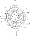
- Fig. 1 is a perspective view of an embodiment of a working element according to the present invention.
- Fig. 1 shows an embodiment of a working element 1 according to the present invention.
- the radial direction X, the direction of gravity Z and the axis of rotation Y form a right-hand system, or a rectangular coordinate system.
- the working element 1 has a central element 11 in its middle.
- the central element 11 extends in the radial direction X in a plate-like manner. Viewed in the direction of the axis of rotation Y, the central element 11 has a circular outer contour.
- the cross-section of the central element 11 is rotationally symmetrical, i.e. identical in both the radial direction X and the direction of gravity Y.
- central element 11 In the middle of the central element 11 there is a cylindrical bore which serves as a bearing section for the central element 11. By means of the bearing section, the central element 11 can be rotatably mounted on a cylindrical projection.
- the central element 11 On one side in the direction of the axis of rotation Y, the central element 11 has a flat second receiving section 11a1 (not visible in Fig. 1 ), on which a spring element 16 rests.
- the central element 11 has six cylindrical first receiving sections 11a1. Screws (not shown) can be inserted into the cylindrical receiving sections from one side, which can be secured from the other side by means of a nut (not shown).
- the spring element 16 has through holes which are aligned with the first support sections 11a1 of the central element.
- the spring element 16 extends in the radial direction X in a plate-like manner and has 16 spring segments 16a which taper in the radial direction X and have a triangular shape.
- the areas between the spring segments 16a can be referred to as slots 16b.
- the side of the spring element 16 in the direction of the axis of rotation Y is the guide surface 12f.
- the rotary component 10 rests flat against the spring element 16 on the guide surface 12f.
- the rotary component 10 extends in the radial direction X in a plate-like manner. At the outer end region in the radial direction X, the rotary component 10 has a projection 12d.
- the projection 12d extends in the radial direction X in a plate-like manner and in the direction of the rotation axis Y and merges by means of a bent edge into the plate-shaped region of the rotary component which extends in the radial direction. Viewed in the direction of the rotation axis Y, the bent edge runs in a circular manner and concentrically to the bearing section of the central element 11.
- the projection 12d can also be referred to as a curvature which runs all the way around in the direction of rotation.
- the curvature has a cutting edge 12c.
- the rotating component 10 has segments 12 which are separated from one another by means of slots 13.
- the segments can pivot relative to one another in the direction of the axis of rotation Y, whereby the radially middle part, which rests against the receiving section 11a1 of the central element 11 by means of the spring element 16, does not pivot.
- the pivoting movement of the segments 12 strips off clods of earth which have accumulated over several (at least two) segments 16.
- Each segment 12 has an immersion edge 12a.
- the immersion edge 12a is the first part of the segment 12 to immerse itself in the soil to be cultivated.
- the direction of rotation of the working element is related to a segment 12 in the direction of the immersion edge 12a around the axis of rotation Y. Viewed in the direction of the axis of rotation Y, the immersion edge 12a is sickle-shaped.
- a segment 12 Opposite the immersion edge 12a, in the opposite direction to the direction of rotation, a segment 12 has a recess 12b.
- the recess 12 supports the stripping of accumulated clumps of earth, which can move freely through the recess after stripping. This prevents stripped clumps of earth from being thrown away by segments, which, after emerging from the soil to be worked, are pressed back into their original position with respect to the axis of rotation Y by means of the spring element 16.
- the recess 12b is curved and positioned in a central area of the edge in the direction of rotation opposite the leading edge.
- the recess 12b reduces the width of a segment 12 by approximately 1/3.
- the recess 12b extends approximately over 1/3 of the length of a segment 12 in the radial direction X.
- the rotary component 10 has through holes that are aligned with the first support sections 11a1 of the central element.
- the screws that are inserted into the first support sections 11a1 can also be inserted through the spring element 16 and the rotary component 10.
- the screws can then be secured on the side of the rotary component 10 that faces in the direction of the axis of rotation.
- the central element 10, spring element 16 and rotary component 10 are coupled.
- the area in which the segments 12 of the rotary component can pivot is outside the area in the radial direction X in which the central element 10, spring element 16 and rotary component 10 are coupled.
- the working element 1 by means of its storage section can be stored on a support element 21 (not shown) of a soil tillage device (not shown) in such a way that the radial direction X of the working element 1 forms an acute angle with the soil tillage direction in which the soil tillage device is pulled over the soil to be tilled. In other words, the working device 1 is inclined to the soil tillage direction.
- the force acts not only in the radial direction X of implement 1, but also in the direction of the axis of rotation Y.
- the component of the force that acts in the direction of the axis of rotation Y is referred to as the transverse force.
- the component of the force that acts in the radial direction X is referred to as the radial force.
- the force on work element 1 can be broken down into two mutually perpendicular components, the radial force and the transverse force.
- the radial force acting on the working element 1 at a distance in the direction of gravity Z away from the axis of rotation Y causes a rotational movement of the working element 1 about the axis of rotation Y.
- the transverse force acting in the direction of the axis of rotation on the side surfaces of segments 12, especially the segments 12 that are immersed in the soil to be worked, causes a deflection of the segments 12 in the direction of the axis of rotation Y.
- the deflection of the segments 12 is a pivoting movement that is large in the radial direction X on the outside, i.e. in the area of the curvature 12d, and is minimal in the area of the central element 11.
- the spring element 16 is thereby tensioned.
- the curvature 12d protrudes in the direction of the rotation axis Y.
- the working element 1 is mounted on the support element in such a way that the force in the soil working direction hits the side of the working element 1 in whose direction the curvature 12d also protrudes. Consequently, in the present embodiment, the transverse force from the direction of the rotation axis Y acts on the segments 12 against the direction of the rotation axis Y. Accordingly, the segments 12d that dip into the soil to be worked are deflected against the direction of the rotation axis Y.
- a strong soil movement takes place against the direction of gravity Z and in the direction of the axis of rotation Y.
- the present embodiment is thus used to create a dam for, for example, a dam culture from the soil to be worked.
- the working element 1 can be mounted on the same support element 21 as before, rotated by 180° about the direction of gravity Y.
- the curvature 12d projects in the opposite direction to the axis of rotation Y. Segments 12 that protrude into the soil to be worked are deflected in the opposite direction to the direction of rotation Y, as before.
- the soil moves in the opposite direction to the direction of gravity Z and in the direction of the axis of rotation Y.
- the soil movement in the direction of the axis of rotation Y is much smaller in this case, since the curvature 12d projecting in the opposite direction supports the soil movement less.
- the working element 1 aligned in this way is used for mechanical weed control.
- a working element 1 for a soil tillage device has a central element 11, which is arranged in a central region of the working element 1, and a rotary component 10, which is rotatable by means of the central element 11 about a rotary axis Y in a direction of rotation and extends from the central element 11 in a radial direction X, which encloses an obtuse angle with the rotary axis Y.
- the rotary component 10 has segments 12, which extend in the radial direction X to the end of the rotary component 10, which have a cutting edge 12c at one end in the radial direction X away from the central element 11, which have an immersion edge 12a on a front side in the direction of rotation and which have a projection 12d which runs around in the direction of rotation and protrudes in the direction of the rotary axis Y.
- the Working element 1 is designed so that the segments 12 are movable relative to each other in the direction of the axis of rotation Y.
Landscapes
- Life Sciences & Earth Sciences (AREA)
- Engineering & Computer Science (AREA)
- Mechanical Engineering (AREA)
- Soil Sciences (AREA)
- Environmental Sciences (AREA)
- Soil Working Implements (AREA)
- Cultivation Receptacles Or Flower-Pots, Or Pots For Seedlings (AREA)
- Cultivation Of Plants (AREA)
Description
- Die vorliegende Erfindung betrifft ein Arbeitselement für ein Bodenbearbeitungsgerät zur Bodenbearbeitung.
- In dem Stand der Technik ist ein Arbeitselement ein Teil eines landwirtschaftlichen Geräts zur Bodenbearbeitung, welches unter anderem für eine mechanische Unkrautbekämpfung aber auch für eine gezielte Erdanhäufung zur Erzeugung von Dämmen für soggenannte Dammkulturen verwendet wird. Das Arbeitselement wird mittels einem Bodenbearbeitungsgerät an einer Zugmaschine angebracht und in Bodenbearbeitungsrichtung über den zu bearbeitenden Boden gezogen.
- FIG. 7 der
DE 10 2016 119 700 A1 zeigt ein Arbeitselement gemäß dem Oberbegriff des Anspruchs 1.US 9 392 737 B2 US 10 039 223 B2 US 5 875 855 A undCA 2 969 875 A1 zeigen weitere gewöhnliche Arbeitselemente. - Der Erfindung liegt die Aufgabe zugrunde, ein Arbeitselement bereitzustellen, das mittels günstiger Gestaltung eine verbesserte Bodenbearbeitung ermöglicht.
- Die vorliegende Erfindung löst die Aufgabe durch ein Arbeitselement gemäß Patentanspruch 1. Vorteilhafte Weiterbildungen sind Gegenstand der Unteransprüche.
- Ein erfindungsgemäßes Arbeitselement für ein Bodenbearbeitungsgerät weist ein Zentralelement, das in einem mittleren Bereich des Arbeitselements angeordnet ist, und ein Rotationsbauteil auf, das mittels dem Zentralelement um eine Drehachse in eine Drehrichtung drehbar ist und sich von dem Zentralelement in einer Radialrichtung erstreckt, die einen stumpfen Winkel mit der Drehachse einschließt. Dabei weist das das Rotationsbauteil Segmente auf, die sich in der Radialrichtung bis zu dem Ende des Rotationsbauteils erstrecken, die an einem Ende in der Radialrichtung entfernt von dem Zentralelement eine Schneide aufweisen, die an einer in Drehrichtung vorderen Seite eine Eintauchkante aufweisen und die einen in Drehrichtung umlaufenden und in Richtung der Drehachse vorstehenden Vorsprung aufweisen. Dabei ist das Arbeitselement so gestaltet, dass die Segmente relativ zueinander in Richtung der Drehachse beweglich sind.
- Ein Segment kann sich an unterschiedlichen Stellen in der Drehrichtung unterschiedlich weit in der Radialrichtung erstrecken. Betrachtet in Richtung der Drehachse kann das Arbeitselement insgesamt somit beispielsweise eine wellenförmige Außenkontur aufweisen. Dies begünstigt die Erdreichbewegung.
- Das Arbeitselement taucht bei der Bodenbearbeitung mit der Eintauchkante in den zu bearbeitenden Boden ein. Durch Drehung des Arbeitselements um die Drehachse in die Drehrichtung wird die Schneide eines Segments in Radialrichtung in den Boden gedrückt. Dabei wird das Arbeitselement in einer Bodenbearbeitungsrichtung durch den zu bearbeitenden Boden bewegt, so dass das Arbeitselement eine Rollbewegung ausführt.
- Die Schneide ist ein in Radialrichtung flach zulaufender Bereich. Die Schneide kann beispielsweise auch ähnlich einer Messerschneide geschärft sein. Die Schneide dient dazu, Unkraut und deren Wurzeln zu zerschneiden und erleichtert ein Eindrücken eines Segments in den Boden. Somit ist die Bodenbearbeitung energieeffizient möglich und ein Verschleiß der Enden in Radialrichtung der Segmente wird reduziert.
- Die Eintauchkante kann in Drehrichtung flach zulaufend sein. Dies erleichtert ein Eintauchen der Eintauchkante in den zu bearbeitenden Boden.
- Die Eintauchkante kann in Drehrichtung gebogen sein. Beispielsweise kann die Eintauchkante sichelförmig sein. Dabei kann die Biegung so ausgeführt sein, dass der gebogene Abschnitt zuerst in den zu bearbeitenden Boden eintaucht. Je näher die Biegung an dem Ende eines Segments in Radialrichtung angeordnet ist, desto mehr unterstützt die Biegung, dass das Arbeitselement eine Rollbewegung ausführt, wenn es durch den zu bearbeitenden Boden geführt wird. Dadurch wird der Energieaufwand für die Bearbeitung des Bodens reduziert und eine energieeffiziente Bodenbearbeitung ermöglicht.
- Außerdem kann die Eintauchkante in dem Bereich ihres Endes in Radialrichtung relativ zu einer Drehebene, die senkrecht zu der Drehachse ist, in Richtung der Drehachse gebogen sein. Dadurch wird die Erdreichbewegung unterstützt.
- Der Vorsprung der Segmente dient dazu, Erdreich entgegen einer Schwerkraftrichtung bis über die Oberfläche des zu bearbeitenden Bodens zu befördern und eine Erdanhäufung zu erzeugen. Die Erdanhäufung kann dazu dienen, in Bodenbearbeitungsrichtung Dämme zu errichten, die zur Bepflanzung mit Dammkulturen verwendet werden können. Die Erdanhäufung kann auch dazu dienen, Unkraut, das sich in dem bewegten Erdreich befindet zu entwurzeln, oder das Unkraut mit Erdreich zu bedecken. Durch das Bedecken des Unkrauts mit Erdreich, wird dem Unkraut Sonnenlicht und Sauerstoff bzw. Kohlendioxyd genommen. Somit wird das Wachstum des Unkrauts verhindert und das Unkraut stirbt ab.
- Der Vorsprung kann sich beispielsweise in der Radialrichtung in einem mittleren Bereich eines Segments befinden. Der Vorsprung kann sich auch an einem Ende eines Segments in der Radialrichtung befinden. Es können auch mehrere Vorsprünge an einem Segment vorgesehen sein, die sich an unterschiedlichen Stellen in der Radialrichtung befinden.
- Durch die Anordnung eines Vorsprungs in Radialrichtung kann bestimmt werden, wie stark die Erdreichbewegung durch die Vorsprünge ausfällt. Ist ein Vorsprung in Radialrichtung nahe an dem Ende eines Segments vorgesehen, führt dieser Vorsprung eine starke Erdreichbewegung durch. Ist ein Vorsprung in Radialrichtung nahe dem Zentralelement vorgesehen, führt dieser Vorsprung eine geringe Erdreichbewegung durch.
- Dadurch, dass die Segmente relativ zueinander in Richtung der Drehachse beweglich sind, können Erdklumpen, die sich an dem Arbeitselement angelagert haben, segmentweise abgestreift werden. Außerdem beschränkt die Beweglichkeit der Segmente relativ zueinander die Größe der sich an dem Arbeitselement anlagernden Erdklumpen. Dadurch wird ein erneutes Eintauchen eines Segments in den zu bearbeitenden Boden erleichtert und die Effizienz der Arbeitselemente wird verbessert. Außerdem wird verhindert, dass Erdklumpen, die sich oberhalb des zu bearbeitenden Bodens von dem Arbeitselement lösen, durch die Luft geschleudert werden und an unerwünschten Stellen, wie beispielsweise einer Dammkultur oder sonstigen Nutzpflanze landen oder zu groß werden. Somit wird die Gefahr verringert, dass bereits angepflanzte Nutzpflanzen durch die Bodenbearbeitung beschädigt werden. Dadurch ist eine wirksame Bodenbearbeitung möglich.
- Die Bewegung der Segmente relativ zueinander ist vorzugsweise eine Schwenkbewegung, die im Bereich des Zentralelements gering ist und an den Enden in Radialrichtung groß ist. Vorzugsweise werden die Segmente geschwenkt, wenn sie in dem zu bearbeitenden Boden eingetaucht sind. Die Auslenkung der Segmente vergrößert sich von dem Eintauchen der Segmente bis zum Auftauchen der Segmente. Wenn die Segmente wieder aus dem zu bearbeitenden Boden auftauchen, schwenken die Segmente vorzugsweise wieder zurück in ihre Ausgangslage bzgl. der Drehachse.
- Dadurch, dass sich die Segmente in Radialrichtung bis zu dem Ende des Rotationsbauteils erstrecken, entsprechen insbesondere die Enden in Radialrichtung des Rotationsbauteils den Enden in Radialrichtung der Segmente.
- Dadurch sind insbesondere Enden in Radialrichtung der Segmente mit den Schneiden relativ zueinander in Richtung der Drehachse beweglich.
- Mittels dem Zentralelement ist das Rotationsbauteil drehbar in zumindest eine Drehrichtung.
- Das Zentralelement kann mittels eines Freilaufmechanismus eine Drehrichtung sperren. Dies gewährleistet, dass das Arbeitselement ausschließlich in seiner Arbeitsdrehrichtung betrieben wird.
- Das Zentralelement kann einen Lagerungsabschnitt aufweisen, der beispielsweise so ausgebildet ist, dass er eine zylindrische Achse so gleitbar aufnimmt, dass das Rotationsbauteil drehbar ist. Ferner kann das Zentralelement zumindest einen Anlageabschnitt aufweisen, mit dem seine Bewegung in Richtung der Drehachse beschränkt werden kann. Alternativ kann der Lagerungsabschnitt des Zentralelements auch so ausgebildet sein, dass er ein Lager, wie ein Radiallager, Schrägkugellager, Kegelrollenlager oder Dergleichen aufnehmen kann.
- Das Rotationsbauteil kann rotationssymmetrisch gestaltet sein. Dies vereinfacht den Herstellungsprozess und das Arbeitselement kann kostengünstig hergestellt werden.
- Das Rotationsbauteil kann sich bezüglich der Richtung der Drehachse senkrecht erstrecken. Das Rotationsbauteil kann aber auch einen stumpfen Winkel mit der Richtung der Drehachse einschließen. Durch die Ausbildung eines stumpfen Winkels des Rotationsbauteils, kann das Rotationsbauteil die Erdreichbewegung der Vorsprünge unterstützen. Dadurch wird die Wirksamkeit der Bodenbearbeitung verbessert.
- Ferner ist ein Vorsprung des erfindungsgemäßen Arbeitselements an einem Ende in Radialrichtung der Segmente und entfernt von dem Zentralelement angeordnet.
- An dem Ende der Segmente in Radialrichtung ist bei einer Drehung der Segmente um die Drehachse der Bewegungsumfang und auch die Bewegungsgeschwindigkeit am größten. Dieser Bereich des Arbeitselements taucht am tiefsten in den zu bearbeitenden Boden ein. Durch Anordnung des Vorsprungs in diesem Bereich ist die daraus resultierende Erdreichbewegung am größten. Somit kann ein Arbeitselement mit möglichst geringem Durchmesser in der Drehebene und möglichst großer Wirksamkeit bezüglich der Erdreichbewegung bereitgestellt werden.
- Dabei kann der Vorsprung so ausgestaltet sein, dass er sich in Radialrichtung vorzugsweise nicht weiter als über die letzten 10% des Segmentes vor dem Ende des Segments erstreckt. Dabei kann die Erstreckung des Vorsprungs in Richtung der Drehachse vorzugsweise geringer als 10% des Außendurchmessers des Arbeitselements in der Drehebene sein. Eine solche Konfiguration nutzt die Vorteile einer großen Erdreichbewegung und gleichzeitig eines geringen Arbeitswiderstandes vorteilhaft aus.
- Ferner kann ein Vorsprung des erfindungsgemäßen Arbeitselements mittels einem Knick gebildet sein, von dem aus sich das Rotationsbauteil zusätzlich zu der Radialrichtung in Richtung der Drehachse erstreckt.
- Damit kann das Segment und der Vorsprung einstückig ausgeführt werden, wobei der Vorsprung mittels Umformen, beispielsweise Biegen, eines Bereiches des Segmentes hergestellt werden kann, das in seinem Ursprungszustand eine Plattenform aufweist. Dies ermöglicht eine kostengünstige Herstellung des Arbeitselements.
- Somit können sich die Vorsprünge mittels einer Knickkante von dem verbleibenden Segment abzeichnen. Betrachtet in Richtung der Drehachse weißt die Knickkante eine Bogenform mit einem bestimmten Biegeradius auf. In diesem Fall kann der Vorsprung als eine Wölbung bezeichnet werden.
- Die Wölbung kann in Drehrichtung umlaufend sein.
- Vorsprünge können separate Bauteile sein, z.B. Bolzen oder Platten, aber auch gebogene Platten oder Schaufeln sein, die in Radialrichtung ausgerichtet sind, und mit dem Segment verbunden sind. Dadurch lassen sich bei Beschädigung einzelner Vorsprünge diese austauschen und eine lange Lebensdauer des gesamten Arbeitselements wird ermöglicht.
- In diesem Fall kann die Position der Vorsprünge in Radialrichtung einstellbar sein, beispielsweise über Langlöcher, die in Radialrichtung ausgerichtet sind und über die die Vorsprünge mittels Schrauben mit den Segmenten verbunden werden können.
- Ferner kann ein Segment eines erfindungsgemäßen Arbeitselements zumindest eine Aussparung haben.
- Die Aussparung dient dazu, dass sich dort die Erdklumpen oder der Mulch ansammeln können, die an den Segmenten anhaften und beim Auftauchen der Segmente aus dem zu bearbeitenden Boden abgestreift werden. Allein durch die Schwerkraft fällt somit ein angesammelter Erdklumpen zu Boden, bzw. verlässt die Oberfläche des zu bearbeitenden Bodens erst gar nicht. Im Gegensatz dazu, ohne die Aussparung, würde ein angesammelter Erdklumpen bei der Bewegung eines Segments, das gerade aus dem zu bearbeitenden Boden auftaucht, zurück in seine Ausgangslage bzgl. der Drehachse, unkontrolliert weggeschleudert werden und könnte an unerwünschten Stellen, wie beispielsweise einer Dammkultur oder sonstigen Nutzpflanze landen. Somit reduzieren die Aussparungen die Gefahr einer Beschädigung einer Nutzpflanze während der Bodenbearbeitung.
- Über eine Gestaltung mittels Schiene und Arretierung kann die Aussparung, bzw. ein in Drehrichtung über die Aussparung hinausragender Bereich in der Radialrichtung verschoben und arretiert werden. Damit kann die Aussparung auf eine gewünschte Position in Radialrichtung eingestellt werden.
- Ferner kann eine Aussparung eines erfindungsgemäßen Arbeitselements in der Radialrichtung in einem mittleren Bereich des Segments und auf einer Außenseite des Segments gegenüber der Eintauchkante positioniert sein.
- Vorzugsweise ist die Aussparung an der Kante eines Segments angeordnet, die der Eintrittskante in Drehrichtung gegenüberliegt. Vorzugsweise ist die Aussparung in der Radialrichtung mittig in einem Segment angeordnet.
- Die Aussparung kann vorzugsweise so gestaltet sein, dass eine Breite des Segments in Drehrichtung nicht kleiner als halb so breit ist, wie eine Breite, die sich für das Segment ergibt, wenn anstatt der Aussparung die hintere Kante gegenüber der Eintauchkante gerade verlaufen würde. Dadurch ist eine ausreichende Festigkeit des durch die Aussparung geschwächten Bereichs gewährleistet.
- Ferner kann die Aussparung so gestaltet sein, dass sie sich in der Radialrichtung nicht weiter als über die Hälfte der Länge des Segments erstreckt. Dadurch ist eine ausreichende Erdreichbewegung mittels der verbleibenden Fläche des Segments gewährleistet.
- Ein Segment kann auch eine zusätzliche Aussparung an der Eintrittskante haben. Dabei kann die zusätzliche Aussparung in dem Segment der Aussparung in Drehrichtung gegenüberliegen.
- Ferner können in einem erfindungsgemäßen Arbeitselement zwischen den Segmenten in Radialrichtung Schlitze vorgesehen sein.
- Die Schlitze haben vorzugsweise eine Breite in der Drehrichtung von 1 mm bis 1,5 mm. Dadurch ist gewährleistet, dass sich die Segmente relativ zueinander in beide Richtungen bezogen auf die Drehachse bewegen können.
- Die Bewegungsfreiheit der Segmente relativ zueinander kann durch Anschlagvorsprünge an zumindest einer der Eintauchkante oder der in Drehrichtung gegenüberliegenden Kante so eingeschränkt sein, dass sich ein Segment bezüglich seines in Drehrichtung nachfolgenden oder vorhergehenden Segments nur in eine Richtung in der Drehachse bewegen kann. Mit anderen Worten kann ein Segment ein nachfolgendes oder vorhergehendes Segment in der Drehrichtung mit zumindest einem Anschlagsvorsprung überlappen.
- Die Segmente in einem erfindungsgemäßen Arbeitselement können aus vorgehärtetem Federstahl hergestellt sein.
- Dies hat zur Folge, dass eine Auslenkung eines Segments lediglich unter Aufbringung einer Querkraft in Richtung der Drehachse möglich ist und dass sich die Segmente wieder zu ihrer ursprünglichen Lage bezüglich der Drehachse zurückbewegen, wenn die Querkraft weggenommen wird.
- Wird die Querkraft unterhalb des zu bearbeitenden Bodens durch den Boden selbst aufgebracht, bewegt sich ein Segment automatisch wieder zurück in seine ursprüngliche Lage, wenn das Segment aus dem Boden auftaucht.
- Diese Kraftaufbringung mittels dem zu bearbeitenden Boden kann beispielsweise erreicht werden, indem das Arbeitselement, das in den Boden eingetaucht ist, nicht in seiner Radialrichtung durch den Boden gezogen wird, sondern in einem Winkel dazu. Mit anderen Worten kann solch eine Querkraft erzeugt werden, wenn die Bodenbearbeitungsrichtung und die Radialrichtung der Arbeitselemente einen Winkel aufweisen.
- Außerdem kann das Segment eine Beschichtung aufweisen, die die Lebensdauer des Arbeitselements erhöht.
- Segmente eines erfindungsgemäßen Arbeitselements können im Wesentlichen plattenförmig in der Radialrichtung sein.
- Somit kann das Rotationbauteil kostengünstig mittels Stanzen aus einem plattenförmigen Flachmaterial hergestellt sein. Dies ermöglicht eine kostengünstige Herstellung der Arbeitselemente.
- Die Seitenflächen der Segmente in der Richtung der Drehachse können Welligkeiten aufweisen. Diese Welligkeiten unterstützen die Erdreichbewegung der Vorsprünge.
- Die Seitenflächen der Segmente in der Richtung der Drehachse können Öffnungen aufweisen, die in Richtung der Drehachse durchgängig sind und sich innerhalb der Segmente befinden. Dadurch kann das Gewicht des Arbeitselements verringert werden. Ferner kann dadurch die Anlagerung von Erdklumpen an den Segmenten reduziert werden. Das ermöglicht eine wirksame Bodenbearbeitung.
- Ein Zentralelement eines erfindungsgemäßen Arbeitselements kann ein separates Bauteil sein.
- Dadurch können Zentralelement und Rotationsbauteil aus unterschiedlichen Materialien hergestellt sein, die speziell für die jeweilige Funktion geeignet sind.
- Beispielsweise kann das Zentralelement aus Gusseisen hergestellt sein, wohingegen das Rotationsbauteil aus einem vorgehärteten Federstahl hergestellt ist. In dem Zentralelement kann mittels Gussrohteil und spanender Bearbeitung beispielsweise mittig im Zentralelement ein Lagersitz für ein Rollenlager kostengünstig hergestellt werden. Das Rotationsbauteil kann beispielsweise mittels Stanzen aus einem plattenförmigen Federstahlmaterial hergestellt werden. Somit ist das Arbeitselement kostengünstig herstellbar.
- Ein Zentralelement eines erfindungsgemäßen Arbeitselements kann zumindest einen Aufnahmeabschnitt aufweisen, um das Rotationsbauteil an dem Zentralelement in Radialrichtung und Achsrichtung zu stützen.
- Beispielsweise kann ein erster Aufnahmeabschnitt ein zylindrischer Vorsprung in Richtung der Drehachse sein, um das Rotationsbauteil in Radialrichtung zu stützen. Dementsprechend kann das Rotationsbauteil eine zylindrische Öffnung aufweisen, die sich ebenfalls in Richtung der Drehachse erstreckt, und die mit dem zylindrischen Vorsprung des Zentralelements in Kontakt bringbar ist.
- Der erste Aufnahmeabschnitt kann mittig in dem Zentralelement vorgesehen sein.
- Beispielsweise kann ein zweiter Aufnahmeabschnitt eine ebene Fläche sein, die sich in dem Zentralelement senkrecht oder in einem stumpfen Winkel zu der Drehachse erstreckt, um das Rotationsbauteil in Richtung der Drehachse zu stützen. Dementsprechend kann das Rotationsbauteil eine ebene Fläche aufweisen, die sich senkrecht oder in einem stumpfen Winkel zu der Drehachse erstreckt und mit der ebenen Fläche des Zentralelements in Kontakt bringbar ist.
- Der zweite Aufnahmeabschnitt kann in Radialrichtung konzentrisch zu dem ersten Aufnahmeabschnitt angeordnet sein.
- Ferner kann ein Arbeitselement Sicherungselemente, wie Schrauben, Bolzen oder Sicherungsringe aufweisen, um das Rotationsbauteil bezüglich dem Zentralelement in Richtung der Drehachse zu positionieren.
- Mittels einer solchen Gestaltung kann das Rotationsbauteil leicht von dem Zentralelement gelöst werden. Ein Rotationsbauteil kann somit auf einfache Weise durch ein anderes Rotationsbauteil ausgetauscht werden. Dies führt zum Einen zu einer flexiblen Anwendbarkeit des Arbeitselements und zum Anderen zu einer erhöhten Lebensdauer des Arbeitselements.
- Segmente eines erfindungsgemäßen Arbeitselements können separat voneinander ausgeführt sein und mittels einem Zentralelement gekoppelt sein.
- Jedes Segment kann einzeln mittels einem Aufnahmeabschnitt in dem Zentralelement an das Zentralelement gekoppelt werden.
- Beispielsweise kann das Zentralelement für jedes Segment als ersten Aufnahmeabschnitt einen zylindrischen Vorsprung in Richtung der Drehachse aufweisen, um das Rotationsbauteil in Radialrichtung zu stützen. Dementsprechend kann das Rotationsbauteil eine zylindrische Öffnung aufweisen, die sich ebenfalls in Richtung der Drehachse erstreckt, und die mit dem zylindrischen Vorsprung des Zentralelements in Kontakt bringbar ist.
- Beispielsweise kann das Zentralelement für jedes Segment als ersten Aufnahmeabschnitt einen Durchgang haben. In den Durchgang können vorstehende Bereiche des Segments oder Sicherungselemente, wie Schrauben, eingeführt werden.
- Beispielsweise kann das Zentralelement für jedes Segment als zweiten Aufnahmeabschnitt eine ebene Fläche aufweisen.
- Ferner kann ein Segment mittels Sicherungselementen, wie Schrauben, Bolzen oder Sicherungsringe in Richtung der Drehachse bezüglich dem Zentralelement positioniert werden.
- Das hat den Vorteil, dass einzelne Segmente leicht durch andere Segmente ausgetauscht werden können. Dies führt zum einen zu einer flexiblen Anwendbarkeit des Arbeitselements und zum anderen zu einer erhöhten Lebensdauer des Arbeitselements.
- Ein Segment kann auch mittels mehrerer erster Aufnahmeabschnitte an das Zentralelement gekoppelt werden. Somit kann eine Verdrehung der Segmente relativ zu dem Zentralelement in Drehrichtung eingeschränkt werden.
- Ferner können mehrere Segmente eine Einheit bilden und einstückig miteinander ausgebildet sein. Das reduziert die notwendige Anzahl an Aufnahmeabschnitten in dem Zentralelement und reduziert die Kosten für die Herstellung des Arbeitselements.
- Segmente eines erfindungsgemäßen Arbeitselements können mittels zumindest einem Federelement geführt werden, das auf die Segmente an zumindest einer Führungsfläche eine Federkraft zum Großteil in Achsrichtung aufbringt.
- Die Führungsfläche ist die Fläche, an der ein Federelement ein Segment berührt.
- Dies hat zur Folge, dass eine Auslenkung eines Segments lediglich unter Aufbringung einer Querkraft in Richtung der Drehachse möglich ist und dass sich die Segmente wieder zu ihrer ursprünglichen Lage bezüglich dem Zentralelement zurückbewegen, wenn die Querkraft weggenommen wird.
- Wird die Querkraft unterhalb des zu bearbeitenden Bodens durch den Boden selbst aufgebracht, bewegt sich ein Segment automatisch wieder zurück in seine ursprüngliche Lage bezüglich dem Zentralelement, wenn das Segment aus dem Boden auftaucht.
- Dadurch, dass die Segmente relativ zueinander in Richtung der Drehachse beweglich sind, können Erdklumpen, die sich an dem Arbeitselement angelagert haben, segmentweise abgestreift werden.
- Ein Federelement kann beispielsweise eine Tellerfeder, eine Blattfeder, eine Spiraldruckfeder oder eine Zugfeder sein, die von einer Seite in Richtung der Drehachse eine Kraft auf die Segmente ausübt.
- Es können auch zwei Federelemente vorgesehen sein, die jeweils von gegenüberliegenden Seiten in Richtung der Drehachse Kräfte auf die Segmente ausüben, die einander entgegengesetzt wirken.
- Der Vorteil einer Tellerfeder oder Blattfeder, die auf alle Segmente wirkt, ist, dass eine Auslenkung in Richtung der Drehachse einzelner Segmente von der Auslenkung eines in Drehrichtung vorherigen oder nachfolgenden Segments abhängt. Dies bewirkt ein sanftes Zurückführen eines Segments in seine ursprüngliche Lage bezüglich dem Zentralelement.
- Wenn ein Federelement in dem Arbeitselement verwendet wird, kann eine Funktionstrennung durchgeführt werden. Dann können Segmente und Federelement aus unterschiedlichen Materialien hergestellt sein, die speziell für die jeweilige Funktion geeignet sind. Beispielsweise kann das Federelement aus einem Federstahl hergestellt sein und die Relativbewegung der Segmente zueinander ermöglichen. Ein Segment kann aus einem starren Material, wie beispielsweise Edelstahl, bestehen. Das macht das Arbeitselement widerstandsfähiger. Ein Segment kann auch aus einem kostengünstigen Material, wie Gusseisen oder Stahl bestehen. Damit kann das Arbeitselement kostengünstig hergestellt werden.
- Wenn die Segmente aus einem starren Material bestehen, kann die Beweglichkeit der Segmente relativ zueinander mittels einem bestimmten Spiel zwischen Segmenten und Aufnahmeabschnitten des Zentralelements gewährleistet sein.
- Ferner kann ein Schwenkmechanismus vorgesehen sein, beispielsweise ein Scharnier, das die Beweglichkeit der Segmente relativ zueinander gewährleistet.
- Ein Federelement kann so gestaltet sein, dass es auf verschiedene Segmente verschieden große Kräfte aufbringt. Beispielsweise kann eine Blattfeder oder Tellerfeder so ausgeführt sein, dass sich, betrachtet in Richtung der Drehachse eine Außenkontur mit unterschiedlichen Krümmungsradien ergibt. Beispielsweise kann eine Blattfeder oder Tellerfeder in Radial- und Umfangsrichtung auch unterschiedliche Materialstärken aufweisen.
- Der Vorteil davon ist, dass sich die Segmente dann bei gleicher Querkraft unterschiedlich weit auslenken. Somit kann beispielsweise eine Dammform eingestellt werden, die in Bodenbearbeitungsrichtung unterschiedlich breit oder hoch ausgebildet ist oder die in Bodenbearbeitungsrichtung und Querrichtung gewellt ist, bzw. eine Schlangenform aufweist.
- Ein Federelement eines erfindungsgemäßen Arbeitselements kann Federsegmente aufweisen, die sich von einem mittleren Bereich des Arbeitselements in der Radialrichtung bis zu dem Ende des Federelements erstrecken.
- Dabei kann jedem Segment des Rotationsbauteils ein eigenes Federsegment zugeordnet sein. Somit kann für jedes Segment einzeln eine bestimmte Auslenkung in Richtung der Drehachse eingestellt werden.
- Es können auch mehrere Segmente des Rotationsbauteils mit dem gleichen Federsegment gestützt werden. Das reduziert die Anzahl an Komponenten des Arbeitselements und das Arbeitselement kann kostengünstig hergestellt werden.
- Ein Federelement eines erfindungssemäßen Arbeitselements kann aus einem Federblech gebildet sein.
- Wird ein Federblech für das Federelement verwendet, kann das Federelement mittels beispielsweise Stanzen kostengünstig hergestellt werden. Das Federblech kann plattenförmig sein.
- Ein Federelement kann auch aus vorgehärtetem Federstahl bestehen. Das verlängert die Lebensdauer des Arbeitselements.
- Zwischen Federsegmenten eines erfindungsgemäßen Arbeitselements können Schlitze vorgesehen sein.
- Die Schlitze zwischen den Federsegmenten haben vorzugsweise eine Breite in der Drehrichtung von mindestens 1 mm. Dadurch ist gewährleistet, dass sich sowohl die Federsegmente, als auch die Segmente des Rotationsbauteils relativ zueinander in beide Richtungen bezogen auf die Drehachse bewegen können.
- Ferner ist es vorteilhaft, wenn die Schlitze zwischen den Federsegmenten die Schlitze zwischen den Segmenten des Rotationsbauteils überragen. Dadurch ist sichergestellt, dass sich die Segmente relativ zueinander in Richtung der Drehrichtung bewegen können.
- Die Schlitze zwischen den Federsegmenten können so gestaltet sein, dass sich für das Federelement, betrachtet in Richtung der Drehachse, eine Kronenform ergibt.
- Federsegmente eines erfindungsgemäßen Arbeitselements können in der Radialrichtung schmal zulaufen.
- Beispielsweise können Federsegmente dreieckförmig gestaltet sein. Dies verlagert einen Kraftangriffspunkt des Federsegments an dem Segment des Rotationsbauteils radial nach außen und entlastet die Aufnahmeabschnitte des Zentralelements und entsprechende Abschnitte in den Segmenten.
- Die Federsegmente können auch tailliert ausgeführt sein. Damit kann eine bestimmte Kraft auf die Führungsfläche verteilt werden, die auf ein Segment des Rotationsbauteils wirkt, wobei die Führungsfläche radial außenliegend und vergrößert gestaltet werden kann. Dies verringert einen Verschleiß an der Führungsfläche.
- Die Anzahl der Federsegmente eines erfindungsgemäßen Arbeitselements kann der Anzahl der Segmente entsprechen.
- Dadurch ist eine Auslenkung einzelner Segmente des Rotationsbauteils einstellbar. Ferner ist eine Rückstellgeschwindigkeit separat einstellbar, mit der sich ein Segment von einer ausgelenkten Position in seine ursprüngliche Lage bzgl. der Drehachse zurückbewegt.
- Ein Segment eines erfindungsgemäßen Arbeitselements kann eine Anschlagfläche aufweisen, die die Bewegung der Segmente relativ zueinander in Richtung der Drehachse beschränkt.
- Bei Auslenkung eines Segments trifft die Anschlagfläche auf einen Anschlag. Mit dieser Anschlagfläche wird die Bewegung des Arbeitselements in Richtung der Drehachse beschränkt.
- Die Anschlagfläche kann auch in einem Federsegment vorgesehen sein.
- Der Anschlag kann beispielsweise ein ringförmiges Metallbauteil sein, das mittig in dem Zentralelement befestigt werden kann. Der Anschlag kann ferner Aufnahmeabschnitte für das Rotationsbauteil und/oder das Federelement aufweisen.
- Der Anschlag kann integral mit dem Zentralelement ausgeführt sein.
- Der Anschlag kann ferner so gestaltet sein, dass eine Position seiner Anschlagsfläche, auf die die Anschlagsfläche des Segments oder Federelements trifft, in Richtung der Drehachse verschieblich und arretierbar ist. Somit kann eine maximale Auslenkung von Segmenten in Richtung der Drehachse eingestellt werden.
- Ein Federelement eines erfindungsgemäßen Arbeitselements kann in dem Zentralelement angebunden sein.
- Dazu weist das Zentralelement Aufnahmeabschnitte auf, vergleichbar mit den Aufnahmeabschnitten für das Rotationsbauteil.
- Federelement und Rotationsbauteil können auch mittels der gleichen Aufnahmeabschnitte aufgenommen werden. Das reduziert die Anzahl an benötigenden Aufnahmeabschnitten, vereinfacht die Form des Zentralelements und ermöglicht somit eine kostengünstige Herstellung des Arbeitselements.
- Federelement und Rotationsbauteil können mittels separater Aufnahmeabschnitte aufgenommen werden, so dass ein Federelement von dem Zentralelement gelöst werden kann, ohne die Arbeitselemente lösen zu müssen. Das erleichtert einen Austausch eines Federelements.
- Federsegmente eines erfindungsgemäßen Arbeitselements können separat voneinander vorgesehen sein und mittels dem Zentralelement gekoppelt sein.
- In diesem Fall stellt das Zentralelement Aufnahmeabschnitte für jedes Federsegment bereit.
- Dies ermöglicht den Austausch einzelner Federsegmente und erhöht somit die Lebensdauer des Arbeitselements.
- Ein erfindungsgemäßes Bodenbearbeitungsgerät weist zumindest ein erfindungsgemäßes Arbeitselement, einen Rahmen, der in Bodenbearbeitungsrichtung über den Boden gezogen wird, zumindest ein Stützelement, das an dem Rahmen angebunden ist und das das Arbeitselement stützt. Das Stützelement weist eine Achse auf, die mit der Richtung der Drehachse des Arbeitselements übereinstimmt, und das Stützelement das Arbeitselement in Richtung der Drehachse positioniert. Weiterhin ist zumindest eine Stützrolle vorgesehen, mittels der das Bodenbearbeitungsgerät so an dem Boden abstützbar ist, dass das Arbeitselement in den Boden ragt.
- Der Rahmen ermöglicht die Anbindung des Bodenbearbeitungsgerätes an ein Zugfahrzeug, das das Bodenbearbeitungsgerät in Bodenbearbeitungsrichtung über den zu bearbeitenden Boden zieht.
- Das Stützelement ist ein Vorsprung in dem Rahmen und dient der Abstützung des Arbeitselements an dem Rahmen. Das Stützelement kann so gestaltet sein, dass es den Lagersitz für einen Innendurchmesser eines Rollenlagers bildet. Die Mittelachse des Lagersitzes bildet dann die Achse, die mit der Drehachse des Arbeitselements übereinstimmt. Das Stützelement kann eine Nut zur Anbringung eines Sicherungsrings aufweisen, um das Rollenlager oder das Arbeitselement in Richtung der Drehachse relativ zu dem Rahmen zu positionieren.
- Außerdem kann das Stützelement einen Abstreifabschnitt aufweisen, dessen Kontur der des Arbeitselements entspricht. Der Abstreifabschnitt ist so an dem Stützelement angeordnet, dass er an dem Teil des Rotationsbauteils, der nach dem Eintauchen in den zu bearbeitenden Boden wieder auftaucht, Erdklumpen abstreift, die sich in dem zu bearbeitenden Boden an dem Rotationsbauteil angelagert haben.
- Außerdem kann das Stützelement eine Anschlagfläche aufweisen, die die Bewegung von Segmenten des Rotationsbauteils relativ zueinander in Richtung der Drehachse beschränkt.
- Eine Stützrolle trägt zumindest einen Teil des Eigengewichts des Arbeitsgeräts. Mittels der Rollenbreite kann eine gewünschte Verdichtung des zu bearbeitenden Bodens eingestellt werden. Die Rolle kann ein keilförmiges Profil in ihrer Drehrichtung aufweisen. Die Rolle kann auch ein teilkreisförmiges Profil in ihrer Drehrichtung aufweisen. Die Rolle kann beispielsweise eine Form eines Tales zwischen zwei Dämmen bestimmen. Eine Packerwalze kann als Rolle verwendet werden.
- Der Abstand in der Schwerkraftrichtung der Stützrolle zu dem Rahmen ist veränderbar und arretierbar. Dadurch kann eine Eindringtiefe des Arbeitselements in den zu bearbeitenden Boden eingestellt werden.
- Ein Stützelement eines erfindungsgemäßen Bodenbearbeitungsgeräts kann in einem stumpfen Winkel zu der Bodenbearbeitungsrichtung vorstehen.
- Die Radialrichtung des montierten Arbeitsgeräts schließt somit, betrachtet aus der Schwerkraftrichtung, mit der Bodenbearbeitungsrichtung einen spitzen Winkel ein. Während der Bodenbearbeitung wird somit auf Bereiche des Arbeitselements, die sich unterhalb der Oberfläche des zu bearbeitenden Bodens befinden, eine Kraft von dem zu bearbeitenden Boden aufgebracht, die als eine Komponente eine Querkraft auf das Arbeitselement hat, also eine Kraft, die senkrecht zu der Drehachse des Arbeitselements auf das Arbeitselement wirkt.
- Die Querkraft erzeugt die Relativbewegung der Segmente des Arbeitselements relativ zueinander in Richtung der Drehachse. Damit ist es möglich, dass Erdklumpen, die sich an den Segmenten angelagert haben, segmentweise abgestreift werden. Außerdem wird unterstützt, dass eine Erdbewegung, betrachtet aus der Schwerkraftrichtung, in Richtung des spitzen Winkels stattfindet. Somit können die Arbeitselemente ihre Aufgabe erfüllen.
- Vorzugsweise kann der spitze Winkel zwischen Bodenbearbeitungsrichtung und Radialrichtung im Bereich von 10° bis 30° liegen.
- Vorzugsweise kann der spitze Winkel so bemessen sein, dass, in Kombination mit einer bestimmten Eindringtiefe des Arbeitselements, die Wölbung eines Segments im Wesentlichen einen 90° Winkel mit dem zu bearbeitenden Boden einschließt, wenn das Segment in den zu bearbeitenden Boden eintaucht.
- Ein Stützelement eines Bodenbearbeitungsgeräts kann in einem stumpfen Winkel zu der Schwerkraftrichtung vorstehen.
- Dadurch schließt die Radialrichtung des Arbeitselements mit der Schwerkraftrichtung, betrachtet in Bodenbearbeitungsrichtung, einen spitzen Winkel ein. Ähnlich der Funktionsweise eines Pflugs wird dadurch eine Erdreichbewegung entgegen der Schwerkraftrichtung unterstützt.
- Der spitze Winkel zwischen Radialrichtung und Schwerkraftrichtung kann vorzugsweise in einem Bereich von 0° bis 20° liegen.
- Vorzugsweise kann der spitze Winkel so bemessen sein, dass, in Kombination mit einer bestimmten Eindringtiefe des Arbeitselements und dem spitzen Winkel zwischen der Radialrichtung und der Bodenbearbeitungsrichtung, die Wölbung eines Segments im Wesentlichen einen 90° Winkel mit dem zu bearbeitenden Boden einschließt, wenn das Segment in den zu bearbeitenden Boden eintaucht.
- Ein Stützelement eines erfindungsgemäßen Bodenbearbeitungsgeräts kann schwenkbar und arretierbar an dem Rahmen angebunden sein.
- Der Rahmen kann beispielsweise Vertikalstreben aufweisen, an deren einem Ende eine Kugelkopfarretierung angebracht ist, mittels der das Stützelement schwenkbar und arretierbar ist. Das hat den Vorteil, dass der Winkel des Stützelements zu der Bodenbearbeitungsrichtung und der Schwerkraftrichtung variabel eingestellt werden kann. Somit kann der Grad der Erdreichbewegung beliebig eingestellt werden und das Bodenbearbeitungsgerät ist vielseitig einsetzbar.
- An einem Ende eines Stützelements eines erfindungsgemäßen Bodenbearbeitungsgeräts in Richtung der Drehachse kann ein Gewinde vorgesehen sein und in einem Bereich in Richtung der Drehachse, entfernt von dem Gewinde, kann ein Anschlag an dem Stützelement vorgesehen sein.
- Der Anschlag kann dazu dienen, einen Innenring eines Rollenlagers in Richtung der Drehachse zu positionieren. Auf das Gewinde kann eine Mutter geschraubt werden, die die Position des Innenrings sichert.
- Ein Stützelement eines erfindungsgemäßen Bodenbearbeitungsgeräts kann so gestaltet sein, dass es das Arbeitselement so stützt, dass der Vorsprung zu dem Stützelement hin orientiert ist oder dass der Vorsprung von dem Stützelement weg orientiert ist.
- Sind mehrere Stützelemente mit Arbeitselement in dem Bodenbearbeitungsgerät vorgesehen, die in einer Querrichtung, senkrecht zu der Bodenbearbeitungsrichtung und der Schwerkraftrichtung, versetzt zueinander angeordnet sind, können in der Querrichtung versetzt zueinander angeordnete Arbeitselemente so orientiert sein, dass die Vorsprünge einander zugewandt sind. Mit einer solchen Orientierung kann beispielsweise ein Damm für eine Dammkultur in dem zu bearbeitenden Boden erzeugt werden.
- Sind die Vorsprünge von in Querrichtung versetzt zueinander angeordneten Arbeitselementen abgewandt voneinander, können die Arbeitsvorsprünge beispielsweise zur mechanischen Unkrautbekämpfung verwendet werden.
- Es können vorzugsweise mehrere Vorsprünge mit Arbeitselement in Bodenbearbeitungsrichtung hintereinander angeordnet sein. Es können vorzugsweise mehrere Paare von einander zu- oder abgewandten Arbeitselementen in Querrichtung nebeneinander angeordnet sein.
-
Fig. 1 ist eine perspektivische Ansicht einer Ausführungsform eines Arbeitselements gemäß der vorliegenden Erfindung. -
Fig. 1 zeigt eine Ausführungsform eines Arbeitselements 1 gemäß der vorliegenden Erfindung. InFig.1 bilden die Radialrichtung X, die Schwerkraftrichtung Z und die Drehachse Y ein Rechtssystem, bzw. ein rechtwinkliges Koordinatensystem. - Das Arbeitselement 1 weist in seiner Mitte ein Zentralelement 11 auf. Das Zentralelement 11 erstreckt sich in der Radialrichtung X plattenförmig. Betrachtet in Richtung der Drehachse Y hat das Zentralelement 11 eine kreisförmige Außenkontur. Der Querschnitt des Zentralelements 11 ist rotationssymmetrisch, also sowohl in der Radialrichtung X, als auch in der Schwerkraftrichtung Y identisch.
- In der Mitte des Zentralelements 11 ist eine zylindrische Bohrung, der dem Zentralelement 11 als Lagerungsabschnitt dient. Mittels dem Lagerungsabschnitt kann das Zentralelement 11 drehbar auf einem zylindrischen Vorsprung gelagert werden.
- Auf einer Seite in Richtung der Drehachse Y hat das Zentralelement 11 einen flächigen zweiten Aufnahmeabschnitt 11a1 (nicht sichtbar in
Fig. 1 ), an dem ein Federelement 16 anliegt. - Außerdem hat das Zentralelement 11 sechs zylindrische erste Aufnahmeabschnitte 11a1. In die zylindrischen Aufnahmeabschnitte können von einer Seite Schrauben (nicht dargestellt) eingeführt werden, welche von der anderen Seite mittels jeweils einer Mutter (nicht dargestellt) gesichert werden können.
- Das Federelement 16 hat Durchgangslöcher, die mit den ersten Auflageabschnitten 11a1 des Zentralelements fluchten.
- Das Federelement 16 erstreckt sich in der Radialrichtung X plattenförmig und weist 16 Federsegmente 16a auf, die in der Radialrichtung X schmal zulaufen und eine dreieckige Form haben. Die Bereiche zwischen den Federsegmenten 16a können als Schlitze 16b bezeichnet werden.
- Die Seite des Federelements 16 in Richtung der Drehachse Y ist die Führungsfläche 12f. An der Führungsfläche 12f liegt das Rotationsbauteil 10 flächig an dem Federelement 16 an.
- Das Rotationsbauteil 10 erstreckt sich in der Radialrichtung X plattenförmig. An dem äußeren Endbereich in der Radialrichtung X weist das Rotationsbauteil 10 einen Vorsprung 12d auf. Der Vorsprung 12d erstreckt sich plattenförmig in die Radialrichtung X und in Richtung der Drehachse Y und geht mittels einer Knickkante in den plattenförmigen Bereich des Rotationsbauteils über, der sich in der Radialrichtung erstreckt. Betrachtet in Richtung der Drehachse Y verläuft die Knickkante kreisförmig und konzentrisch zu dem Lagerungsabschnitt des Zentralelements 11. Der Vorsprung 12d kann auch als Wölbung bezeichnet werden, die in Drehrichtung umlaufend ist.
- Am Ende in der Radialrichtung weist die Wölbung eine Schneide 12c auf.
- Das Rotationsbauteil 10 weist Segmente 12 auf, die mittels Schlitzen 13 voneinander getrennt sind. Die Segmente können relativ zueinander in Richtung der Drehachse Y schwenken, wobei der radial mittlere Teil, der mittels dem Federelement 16 an dem Aufnahmeabschnitt 11a1 des Zentralelements 11 anliegt, nicht schwenkt. Durch die Schwenkbewegung der Segmente 12 werden Erdklumpen abgestreift, die sich über mehrere (zumindest zwei) Segmente 16 hinweg angelagert haben
- Jedes Segment 12 weist eine Eintauchkante 12a auf. Bei der Bodenbearbeitung taucht die Eintauchkante 12a als erster Bestandteil des Segments 12 in den zu bearbeitenden Boden ein. Die Drehrichtung des Arbeitselements ist bezogen auf ein Segment 12 in Richtung der Eintauchkante 12a um die Drehachse Y herum. Betrachtet in Richtung der Drehachse Y ist die Eintauchkante 12a sichelförmig.
- Gegenüber der Eintauchkante 12a entgegen der Drehrichtung weist ein Segment 12 eine Aussparung 12b auf. Die Aussparung 12 unterstützt das Abstreifen von angelagerten Erdklumpen, welche sich nach dem Abstreifen frei durch die Aussparung hindurchbewegen können. Dadurch wird verhindert, dass abgestreifte Erdklumpen von Segmenten weggeschleudert werden, die nach einem Auftauchen aus dem zu bearbeitenden Boden mittels dem Federelement 16 zurück in ihre ursprüngliche Lage bezüglich der Drehachse Y gedrückt werden.
- Die Aussparung 12b ist bogenförmig gestaltet und in einem mittleren Bereich der Kante in Drehrichtung gegenüber der Eintrittskante positioniert. Die Aussparung 12b verringert die Breite eines Segments 12 um ca. 1/3. Die Aussparung 12b erstreckt sich ca. über 1/3 der Länge eines Segments 12 in Radialrichtung X.
- Das Rotationsbauteil 10 hat Durchgangslöcher die mit den die mit den ersten Auflageabschnitten 11a1 der Zentralelements fluchten. Somit können die Schrauben, die in die ersten Auflageabschnitte 11a1 eingeschoben werden, auch durch das Federelement 16 und das Rotationsbauteil 10 eingeschoben werden. Die Schrauben können dann auf der Seite des Rotationsbauteils 10, das in Richtung der Drehachse weist, gesichert werden. Somit sind Zentralelement 10, Federelement 16 und Rotationsbauteil 10 gekoppelt. Der Bereich, in dem die Segmente 12 des Rotationsbauteils schwenkbar sind, ist in Radialrichtung X außerhalb des Bereichs, in dem Zentralelement 10, Federelement 16 und Rotationsbauteil 10 gekoppelt sind.
- Das Arbeitselement 1 mittels seinem Lagerungsabschnitt kann so auf einem Stützelement 21 (nicht abgebildet) eines Bodenbearbeitungsgeräts (nicht abgebildet) gelagert werden, dass die Radialrichtung X des Arbeitselements 1 mit der Bodenbearbeitungsrichtung, in der das Bodenbearbeitungsgerät über den zu bearbeitenden Boden gezogen wird, einen spitzen Winkel einschließt. Mit anderen Worten steht das Arbeitsgerät 1 schräg zu der Bodenbearbeitungsrichtung. Bei der Bodenbearbeitung ragt ein in Schwerkraftrichtung Y unterer Teil des Arbeitsgeräts 1 in den zu bearbeitenden Boden. Auf diesen Teil des Arbeitsgeräts 1 übt der zu bearbeitende Boden eine Kraft entgegen der Bodenbearbeitungsrichtung aus. Da das Arbeitsgerät 1 schräg zu der Bodenbearbeitungsrichtung steht, wirkt die Kraft nicht nur in der Radialrichtung X des Arbeitsgeräts 1, sondern auch in Richtung der Drehachse Y. Die Komponente der Kraft, die in Richtung der Drehachse Y wird, wird als Querkraft bezeichnet. Die Komponente der Kraft, die in Radialrichtung X wirkt, wird als Radialkraft bezeichnet. Mit anderen Worten kann die Kraft auf das Arbeitselement 1 in zwei senkrecht zueinanderstehende Komponenten, die Radialkraft und die Querkraft, zerlegt werden.
- Die Radialkraft, die in einem Abstand in der Schwerkraftrichtung Z entfernt von der Drehachse Y auf das Arbeitselement 1 wirkt, bewirkt eine Drehbewegung des Arbeitselements 1 um die Drehachse Y.
- Die Querkraft, die in Richtung der Drehachse auf Seitenflächen von Segmenten 12, vor allem den Segmenten 12 wirkt, die in den zu bearbeitenden Boden eingetaucht sind, bewirkt eine Auslenkung der Segmente 12 in Richtung der Drehachse Y. Die Auslenkung der Segmente 12 ist eine Schwenkbewegung, die in der Radialrichtung X außen, also im Bereich der Wölbung 12d, groß ist, und im Bereich des Zentralelements 11 minimal ist. Dabei wird das Federelement 16 gespannt.
- In der vorliegenden Ausführungsform ist die Wölbung 12d in Richtung der Drehachse Y vorspringend. Das Arbeitselement 1 ist so auf dem Stützelement gelagert, dass die Kraft in Bodenbearbeitungsrichtung auf die Seite des Arbeitselements 1 trifft, in deren Richtung auch die Wölbung 12d vorspringt. Folglich wirkt in dem vorliegenden Ausführungsbeispiel die Querkraft aus der Richtung der Drehachse Y auf die Segmente 12 entgegen der Richtung der Drehachse Y. Dementsprechend werden die Segmente 12d, die in den zu bearbeitenden Boden tauchen, entgegen der Richtung der Drehachse Y ausgelenkt.
- Wenn die Segmente 12 wieder aus dem zu bearbeitenden Boden auftaucht, ist keine Querkraft mehr an diesen Segmenten 12 anliegend. Deswegen werden diese Segmente 12 mittels der Spannkraft des Federelements 16 wieder zu ihrer ursprünglichen Lage bezüglich dem Zentralelement 11 zurückbewegt.
- Somit Findet in der vorliegenden Ausführungsform eine starke Erdreichbewegung entgegen der Schwerkraftrichtung Z und in Richtung der Drehachse Y statt. Die vorliegende Ausführungsform wird somit dazu verwendet, einen Damm für beispielsweise eine Dammkultur aus dem zu bearbeitenden Boden zu erzeugen.
- Alternativ, kann das Arbeitselement 1 um 180° gedreht um die Schwerkraftrichtung Y auf demselben Stützelement 21, wie zuvor, gelagert werden. In diesem Fall springt die Wölbung 12d entgegen der Richtung der Drehachse Y vor. Segmente 12, die in den zu bearbeitenden Boden ragen, werden, wie zuvor, entgegen der Drehrichtung Y ausgelenkt. Wie zuvor findet eine Erdreichbewegung entgegen der Schwerkraftrichtung Z und in Richtung der Drehachse Y statt. Allerdings ist die Erdreichbewegung in diesem Fall in Richtung der Drehachse Y wesentlich geringer, das die in entgegengesetzte Richtung vorspringende Wölbung 12d die Erdreichbewegung weniger unterstützt. Das so ausgerichtete Arbeitselement 1, wird zur mechanischen Unkrautvernichtung verwendet.
- Ein Arbeitselement 1 für ein Bodenbearbeitungsgerät weist ein Zentralelement 11, das in einem mittleren Bereich des Arbeitselements 1 angeordnet ist, und ein Rotationsbauteil 10 auf, das mittels dem Zentralelement 11 um eine Drehachse Y in eine Drehrichtung drehbar ist und sich von dem Zentralelement 11 in einer Radialrichtung X erstreckt, die einen stumpfen Winkel mit der Drehachse Y einschließt. Dabei weist das das Rotationsbauteil 10 Segmente 12 auf, die sich in der Radialrichtung X bis zu dem Ende des Rotationsbauteils 10 erstrecken, die an einem Ende in der Radialrichtung X entfernt von dem Zentralelement 11 eine Schneide 12c aufweisen, die an einer in Drehrichtung vorderen Seite eine Eintauchkante 12a aufweisen und die einen in Drehrichtung umlaufenden und in Richtung der Drehachse Y vorstehenden Vorsprung 12d aufweisen. Dabei ist das Arbeitselement 1 so gestaltet, dass die Segmente 12 relativ zueinander in Richtung der Drehachse Y beweglich sind.
Claims (25)
- Arbeitselement (1) für ein Bodenbearbeitungsgerät, wobei das Arbeitselement (1) aufweist:ein Zentralelement (11), das in einem mittleren Bereich des Arbeitselements (1) angeordnet ist, undein Rotationsbauteil (10), das mittels dem Zentralelement (11) um eine Drehachse (Y) in eine Drehrichtung drehbar ist und sich von dem Zentralelement (11) in einer Radialrichtung (X) erstreckt, die senkrecht zu der Drehachse (Y) ist oder einen stumpfen Winkel mit der Drehachse (Y) einschließt, wobeidas Rotationsbauteil (10) Segmente (12) aufweist, die sich in der Radialrichtung (X) bis zu dem Ende des Rotationsbauteils (10) erstrecken, die an einem Ende in der Radialrichtung (X) entfernt von dem Zentralelement (11) eine Schneide (12c) aufweisen, die an einer in Drehrichtung vorderen Seite eine Eintauchkante (12a) aufweisen und die einen in Drehrichtung umlaufenden und in Richtung der Drehachse (Y) vorstehenden Vorsprung (12d) aufweisen, unddas Arbeitselement (1) so gestaltet ist, dass die Segmente (12) relativ zueinander in der Richtung der Drehachse (Y) beweglich sind,dadurch gekennzeichnet, dassder Vorsprung (12d) an einem Ende in Radialrichtung (X) der Segmente (12) entfernt von dem Zentralelement (11) angeordnet ist.
- Arbeitselement (1) nach Anspruch 1, wobei der Vorsprung (12d) mittels einem Knick gebildet wird, von dem aus sich das Rotationsbauteil (10) zusätzlich zu der Radialrichtung (X) in Richtung der Drehachse (Y) erstreckt.
- Arbeitselement (1) nach Anspruch 1 bis 2, wobei ein Segment (12) zumindest eine Aussparung (12b) hat.
- Arbeitselement (1) nach Anspruch 3, wobei eine Aussparung (12b) in der Radialrichtung (X) in einem mittleren Bereich des Segments (12) und auf einer Außenseite des Segments (12) gegenüber der Eintauchkante (12a) positioniert ist.
- Arbeitselement (1) nach Anspruch 1 bis 4, wobei zwischen den Segmenten (12) in Radialrichtung (X) Schlitze (13) vorgesehen sind.
- Arbeitselement (1) nach Anspruch 1 bis 5, wobei die Segmente (12) aus vorgehärtetem Federstahl hergestellt sind.
- Arbeitselement (1) nach Anspruch 1 bis 6 wobei die Segmente (12) im Wesentlichen plattenförmig in der Radialrichtung (X) sind.
- Arbeitselement (1) nach Anspruch 1 bis 7, wobei das Zentralelement (11) ein separates Bauteil ist.
- Arbeitselement (1) nach Anspruch 8, wobei das Zentralelement (11) zumindest einen Aufnahmeabschnitt (11a) aufweist, um das Rotationsbauteil (10) an dem Zentralelement (11) in Radialrichtung (X) und Achsrichtung (Y) zu stützen.
- Arbeitselement (1) nach Anspruch 8 bis 9, wobei die Segmente (12) separat voneinander sind und mittels dem Zentralelement (11) gekoppelt sind.
- Arbeitselement (1) nach Anspruch 1 bis 10, wobei die Segmente (12) mittels zumindest einem Federelement (16) geführt werden, das auf die Segmente (12) an zumindest einer Führungsfläche (12f) eine Federkraft zum Großteil in Achsrichtung (Y) aufbringt.
- Arbeitselement (1) nach Anspruch 11, wobei ein Federelement (16) Federsegmente (16a) aufweist, die sich von einem mittleren Bereich des Arbeitselements (1) in der Radialrichtung (X) bis zu dem Ende des Federelements (16) erstrecken.
- Arbeitselement (1) nach Anspruch 11 bis 12, wobei ein Federelement (16) aus einem Federblech gebildet wird.
- Arbeitselement (1) nach Anspruch 11 bis 13, wobei zwischen den Federsegmenten (16a) Schlitze (16b) vorgesehen sind.
- Arbeitselement (1) nach Anspruch 11 bis 14, wobei die Federsegmente in der Radialrichtung (X) schmal zulaufen.
- Arbeitselement (1) nach Anspruch 11 bis 15, wobei die Anzahl der Federsegmente (16a) der Anzahl der Segmente (12) entspricht.
- Arbeitselement (1) nach Anspruch 1 bis 16, wobei ein Segment (12) eine Anschlagfläche (12e) aufweist, die die Bewegung der Segmente (12) relativ zueinander in Richtung der Drehachse (Y) beschränkt.
- Arbeitselement (1) nach Anspruch 8 bis 16, wobei das Federelement (16) in dem Zentralelement (11) angebunden ist.
- Arbeitselement (1) nach Anspruch 18, wobei die Federsegmente (16a) separat voneinander vorgesehen sind und mittels dem Zentralelement (11) gekoppelt sind.
- Bodenbearbeitungsgerät mit:zumindest einem Arbeitselement (1)einem Rahmen (2), der in Bodenbearbeitungsrichtung (X1) über den Boden gezogen wird,zumindest einem Stützelement, das an dem Rahmen (2) angebunden ist und das das Arbeitselement (1) stützt, wobei das Stützelement eine Achse aufweist, die mit der Achsrichtung der Drehachse (Y) des Arbeitselements (1) übereinstimmt, und das Stützelement das Arbeitselement (1) in Richtung der Drehachse (Y) positioniert, undzumindest einer Stützrolle (24), mittels der das Bodenbearbeitungsgerät so an dem Boden abstützbar ist, dass das Arbeitselement (1) in den Boden ragt.
- Bodenbearbeitungsgerät nach Anspruch 20, wobei das Stützelement in einem stumpfen Winkel zu der Bodenbearbeitungsrichtung vorsteht.
- Bodenbearbeitungsgerät nach Anspruch 20 bis 21, wobei das Stützelement in einem stumpfen Winkel zu einer Schwerkraftrichtung (Z) vorsteht.
- Bodenbearbeitungsgerät nach Anspruch 20 bis 22, wobei ein Stützelement schwenkbar und arretierbar an dem Rahmen (2) angebunden ist.
- Bodenbearbeitungsgerät nach Anspruch 20 bis 23, wobei an einem Ende des Stützelements in Richtung der Drehachse (Y) ein Gewinde vorgesehen ist und in einem Bereich in Richtung der Drehachse (Y), entfernt von dem Gewinde, ein Anschlag an dem Stützelement vorgesehen ist.
- Bodenbearbeitungsgerät nach Anspruch 20 bis 24, wobei das Stützelement so gestaltet ist, dass es das Arbeitselement (1) so stützt, dass der Vorsprung (12d) zu dem Stützelement hin orientiert ist oder dass der Vorsprung (12d) von dem Stützelement weg orientiert ist.
Applications Claiming Priority (1)
| Application Number | Priority Date | Filing Date | Title |
|---|---|---|---|
| DE102021119841.0A DE102021119841A1 (de) | 2021-07-30 | 2021-07-30 | Arbeitselement zur Bodenbearbeitung |
Publications (2)
| Publication Number | Publication Date |
|---|---|
| EP4124218A1 EP4124218A1 (de) | 2023-02-01 |
| EP4124218B1 true EP4124218B1 (de) | 2024-11-13 |
Family
ID=82780821
Family Applications (1)
| Application Number | Title | Priority Date | Filing Date |
|---|---|---|---|
| EP22187726.9A Active EP4124218B1 (de) | 2021-07-30 | 2022-07-29 | Arbeitselement zur bodenbearbeitung |
Country Status (2)
| Country | Link |
|---|---|
| EP (1) | EP4124218B1 (de) |
| DE (1) | DE102021119841A1 (de) |
Family Cites Families (7)
| Publication number | Priority date | Publication date | Assignee | Title |
|---|---|---|---|---|
| AT383246B (de) | 1985-09-10 | 1987-06-10 | Herz Akm Armaturen Kessel Und | Landwirtschaftliches bodenbearbeitungsgeraet |
| USD379464S (en) * | 1996-03-07 | 1997-05-27 | May-Wes Manufacturing, Inc. | Row crop rolling shield |
| SE523809E (sv) | 2002-07-05 | 2006-04-25 | Vaederstad Verken Ab | En jordbearbetningsenhet med vinkelställda tallrikar |
| US10506754B2 (en) * | 2013-01-25 | 2019-12-17 | Prescriptiona Tillage Technology, Llc | Variable tooth coulter blade with sized inserts |
| DK3616484T3 (da) * | 2013-07-26 | 2023-07-24 | Natt Tools Group Inc | Bølget tallerken med indhak |
| CN104982108B (zh) * | 2015-06-10 | 2017-04-05 | 吉林大学 | 一种免耕播种机条带松碎土壤机构 |
| DE102016119700A1 (de) * | 2016-10-17 | 2018-04-19 | Karin Sekler | Bearbeitungsvorrichtung für Pflanzenrückstände |
-
2021
- 2021-07-30 DE DE102021119841.0A patent/DE102021119841A1/de active Pending
-
2022
- 2022-07-29 EP EP22187726.9A patent/EP4124218B1/de active Active
Also Published As
| Publication number | Publication date |
|---|---|
| EP4124218A1 (de) | 2023-02-01 |
| DE102021119841A1 (de) | 2023-02-02 |
Similar Documents
| Publication | Publication Date | Title |
|---|---|---|
| EP3753383B1 (de) | Schneidelement | |
| DE2657002C3 (de) | Fräswerkzeuge für Sämaschinen | |
| DE60037458T3 (de) | Landwirtschaftliches Gerät | |
| WO2018146263A1 (de) | Pflugvorrichtung mit zwei schneideelementen | |
| EP0070396A1 (de) | Schichtengrubber mit den Arbeitswerkzeugen zugeordneter Anpresswalze | |
| EP1116435B1 (de) | Vorrichtung zum Verpflanzen von Bäumen oder Sträuchern | |
| DE3318619A1 (de) | Bodenbearbeitungsmaschine | |
| EP4124218B1 (de) | Arbeitselement zur bodenbearbeitung | |
| EP0150731A2 (de) | Handgerät zum Auflockern von Gartenboden | |
| DE102019200171B4 (de) | Bodenbearbeitungsgerät | |
| DE3743032A1 (de) | Auf dem boden abrollende andruckrolle oder -walze | |
| DE202021104077U1 (de) | Arbeitselement zur Bodenbearbeitung | |
| DE202015104423U1 (de) | Messersatz und Mähaggregat mit einer Vielzahl von Messersätzen | |
| DE10346909B4 (de) | Spargelerntegerät | |
| DE2806960A1 (de) | Landwirtschaftliche maschine | |
| DE10153964A1 (de) | Bodenbearbeitungsgerät zum Einebnen, Zerkleinern und Rückverfestigen des Bodens | |
| EP0260643A2 (de) | Vertikutiermesser für ein Vertikutiergerät | |
| DE3431333A1 (de) | Bodenwalze fuer die ackerbestellung | |
| DE2850226B1 (de) | Bodenbearbeitungsmaschine | |
| DE3336455C2 (de) | Vorrichtung zur Herstellung parallelwandiger Rillen in Grünland und Rasenflächen | |
| EP3955720A1 (de) | Scharverschleiss-reduzierung | |
| EP4537644B1 (de) | Bodenbearbeitungsgerät | |
| DE3005283A1 (de) | Blatt fuer bodenbearbeitungsgeraete | |
| DE396550C (de) | Geraet zur Moorkultur | |
| DE202023106960U1 (de) | Rollrasen-Erntemaschine und Erntemesser hierfür |
Legal Events
| Date | Code | Title | Description |
|---|---|---|---|
| PUAI | Public reference made under article 153(3) epc to a published international application that has entered the european phase |
Free format text: ORIGINAL CODE: 0009012 |
|
| STAA | Information on the status of an ep patent application or granted ep patent |
Free format text: STATUS: THE APPLICATION HAS BEEN PUBLISHED |
|
| AK | Designated contracting states |
Kind code of ref document: A1 Designated state(s): AL AT BE BG CH CY CZ DE DK EE ES FI FR GB GR HR HU IE IS IT LI LT LU LV MC MK MT NL NO PL PT RO RS SE SI SK SM TR |
|
| STAA | Information on the status of an ep patent application or granted ep patent |
Free format text: STATUS: REQUEST FOR EXAMINATION WAS MADE |
|
| 17P | Request for examination filed |
Effective date: 20230731 |
|
| RBV | Designated contracting states (corrected) |
Designated state(s): AL AT BE BG CH CY CZ DE DK EE ES FI FR GB GR HR HU IE IS IT LI LT LU LV MC MK MT NL NO PL PT RO RS SE SI SK SM TR |
|
| GRAP | Despatch of communication of intention to grant a patent |
Free format text: ORIGINAL CODE: EPIDOSNIGR1 |
|
| STAA | Information on the status of an ep patent application or granted ep patent |
Free format text: STATUS: GRANT OF PATENT IS INTENDED |
|
| INTG | Intention to grant announced |
Effective date: 20240610 |
|
| GRAS | Grant fee paid |
Free format text: ORIGINAL CODE: EPIDOSNIGR3 |
|
| GRAA | (expected) grant |
Free format text: ORIGINAL CODE: 0009210 |
|
| STAA | Information on the status of an ep patent application or granted ep patent |
Free format text: STATUS: THE PATENT HAS BEEN GRANTED |
|
| AK | Designated contracting states |
Kind code of ref document: B1 Designated state(s): AL AT BE BG CH CY CZ DE DK EE ES FI FR GB GR HR HU IE IS IT LI LT LU LV MC MK MT NL NO PL PT RO RS SE SI SK SM TR |
|
| P01 | Opt-out of the competence of the unified patent court (upc) registered |
Free format text: CASE NUMBER: APP_55393/2024 Effective date: 20241009 |
|
| REG | Reference to a national code |
Ref country code: GB Ref legal event code: FG4D Free format text: NOT ENGLISH |
|
| REG | Reference to a national code |
Ref country code: CH Ref legal event code: EP |
|
| REG | Reference to a national code |
Ref country code: DE Ref legal event code: R096 Ref document number: 502022002119 Country of ref document: DE |
|
| REG | Reference to a national code |
Ref country code: IE Ref legal event code: FG4D Free format text: LANGUAGE OF EP DOCUMENT: GERMAN |
|
| REG | Reference to a national code |
Ref country code: LT Ref legal event code: MG9D |
|
| REG | Reference to a national code |
Ref country code: NL Ref legal event code: MP Effective date: 20241113 |
|
| PG25 | Lapsed in a contracting state [announced via postgrant information from national office to epo] |
Ref country code: IS Free format text: LAPSE BECAUSE OF FAILURE TO SUBMIT A TRANSLATION OF THE DESCRIPTION OR TO PAY THE FEE WITHIN THE PRESCRIBED TIME-LIMIT Effective date: 20250313 Ref country code: HR Free format text: LAPSE BECAUSE OF FAILURE TO SUBMIT A TRANSLATION OF THE DESCRIPTION OR TO PAY THE FEE WITHIN THE PRESCRIBED TIME-LIMIT Effective date: 20241113 Ref country code: PT Free format text: LAPSE BECAUSE OF FAILURE TO SUBMIT A TRANSLATION OF THE DESCRIPTION OR TO PAY THE FEE WITHIN THE PRESCRIBED TIME-LIMIT Effective date: 20250313 |
|
| PG25 | Lapsed in a contracting state [announced via postgrant information from national office to epo] |
Ref country code: FI Free format text: LAPSE BECAUSE OF FAILURE TO SUBMIT A TRANSLATION OF THE DESCRIPTION OR TO PAY THE FEE WITHIN THE PRESCRIBED TIME-LIMIT Effective date: 20241113 Ref country code: NL Free format text: LAPSE BECAUSE OF FAILURE TO SUBMIT A TRANSLATION OF THE DESCRIPTION OR TO PAY THE FEE WITHIN THE PRESCRIBED TIME-LIMIT Effective date: 20241113 |
|
| PG25 | Lapsed in a contracting state [announced via postgrant information from national office to epo] |
Ref country code: BG Free format text: LAPSE BECAUSE OF FAILURE TO SUBMIT A TRANSLATION OF THE DESCRIPTION OR TO PAY THE FEE WITHIN THE PRESCRIBED TIME-LIMIT Effective date: 20241113 |
|
| PG25 | Lapsed in a contracting state [announced via postgrant information from national office to epo] |
Ref country code: ES Free format text: LAPSE BECAUSE OF FAILURE TO SUBMIT A TRANSLATION OF THE DESCRIPTION OR TO PAY THE FEE WITHIN THE PRESCRIBED TIME-LIMIT Effective date: 20241113 |
|
| PG25 | Lapsed in a contracting state [announced via postgrant information from national office to epo] |
Ref country code: NO Free format text: LAPSE BECAUSE OF FAILURE TO SUBMIT A TRANSLATION OF THE DESCRIPTION OR TO PAY THE FEE WITHIN THE PRESCRIBED TIME-LIMIT Effective date: 20250213 |
|
| PG25 | Lapsed in a contracting state [announced via postgrant information from national office to epo] |
Ref country code: LV Free format text: LAPSE BECAUSE OF FAILURE TO SUBMIT A TRANSLATION OF THE DESCRIPTION OR TO PAY THE FEE WITHIN THE PRESCRIBED TIME-LIMIT Effective date: 20241113 Ref country code: GR Free format text: LAPSE BECAUSE OF FAILURE TO SUBMIT A TRANSLATION OF THE DESCRIPTION OR TO PAY THE FEE WITHIN THE PRESCRIBED TIME-LIMIT Effective date: 20250214 |
|
| PG25 | Lapsed in a contracting state [announced via postgrant information from national office to epo] |
Ref country code: PL Free format text: LAPSE BECAUSE OF FAILURE TO SUBMIT A TRANSLATION OF THE DESCRIPTION OR TO PAY THE FEE WITHIN THE PRESCRIBED TIME-LIMIT Effective date: 20241113 |
|
| PG25 | Lapsed in a contracting state [announced via postgrant information from national office to epo] |
Ref country code: RS Free format text: LAPSE BECAUSE OF FAILURE TO SUBMIT A TRANSLATION OF THE DESCRIPTION OR TO PAY THE FEE WITHIN THE PRESCRIBED TIME-LIMIT Effective date: 20250213 |
|
| PG25 | Lapsed in a contracting state [announced via postgrant information from national office to epo] |
Ref country code: SM Free format text: LAPSE BECAUSE OF FAILURE TO SUBMIT A TRANSLATION OF THE DESCRIPTION OR TO PAY THE FEE WITHIN THE PRESCRIBED TIME-LIMIT Effective date: 20241113 |
|
| PG25 | Lapsed in a contracting state [announced via postgrant information from national office to epo] |
Ref country code: DK Free format text: LAPSE BECAUSE OF FAILURE TO SUBMIT A TRANSLATION OF THE DESCRIPTION OR TO PAY THE FEE WITHIN THE PRESCRIBED TIME-LIMIT Effective date: 20241113 |
|
| PG25 | Lapsed in a contracting state [announced via postgrant information from national office to epo] |
Ref country code: EE Free format text: LAPSE BECAUSE OF FAILURE TO SUBMIT A TRANSLATION OF THE DESCRIPTION OR TO PAY THE FEE WITHIN THE PRESCRIBED TIME-LIMIT Effective date: 20241113 |
|
| PG25 | Lapsed in a contracting state [announced via postgrant information from national office to epo] |
Ref country code: RO Free format text: LAPSE BECAUSE OF FAILURE TO SUBMIT A TRANSLATION OF THE DESCRIPTION OR TO PAY THE FEE WITHIN THE PRESCRIBED TIME-LIMIT Effective date: 20241113 |
|
| PG25 | Lapsed in a contracting state [announced via postgrant information from national office to epo] |
Ref country code: SK Free format text: LAPSE BECAUSE OF FAILURE TO SUBMIT A TRANSLATION OF THE DESCRIPTION OR TO PAY THE FEE WITHIN THE PRESCRIBED TIME-LIMIT Effective date: 20241113 |
|
| PG25 | Lapsed in a contracting state [announced via postgrant information from national office to epo] |
Ref country code: CZ Free format text: LAPSE BECAUSE OF FAILURE TO SUBMIT A TRANSLATION OF THE DESCRIPTION OR TO PAY THE FEE WITHIN THE PRESCRIBED TIME-LIMIT Effective date: 20241113 |
|
| PG25 | Lapsed in a contracting state [announced via postgrant information from national office to epo] |
Ref country code: IT Free format text: LAPSE BECAUSE OF FAILURE TO SUBMIT A TRANSLATION OF THE DESCRIPTION OR TO PAY THE FEE WITHIN THE PRESCRIBED TIME-LIMIT Effective date: 20241113 |
|
| REG | Reference to a national code |
Ref country code: DE Ref legal event code: R097 Ref document number: 502022002119 Country of ref document: DE |
|
| PG25 | Lapsed in a contracting state [announced via postgrant information from national office to epo] |
Ref country code: SE Free format text: LAPSE BECAUSE OF FAILURE TO SUBMIT A TRANSLATION OF THE DESCRIPTION OR TO PAY THE FEE WITHIN THE PRESCRIBED TIME-LIMIT Effective date: 20241113 |
|
| PLBE | No opposition filed within time limit |
Free format text: ORIGINAL CODE: 0009261 |
|
| STAA | Information on the status of an ep patent application or granted ep patent |
Free format text: STATUS: NO OPPOSITION FILED WITHIN TIME LIMIT |
|
| PGFP | Annual fee paid to national office [announced via postgrant information from national office to epo] |
Ref country code: DE Payment date: 20250728 Year of fee payment: 4 |
|
| PGFP | Annual fee paid to national office [announced via postgrant information from national office to epo] |
Ref country code: AT Payment date: 20251020 Year of fee payment: 4 Ref country code: FR Payment date: 20250723 Year of fee payment: 4 |
|
| PGFP | Annual fee paid to national office [announced via postgrant information from national office to epo] |
Ref country code: CH Payment date: 20250801 Year of fee payment: 4 |
|
| 26N | No opposition filed |
Effective date: 20250814 |