EP4123763B1 - Stromsammler für sekundärbatterie und sekundärbatterie - Google Patents
Stromsammler für sekundärbatterie und sekundärbatterie Download PDFInfo
- Publication number
- EP4123763B1 EP4123763B1 EP22171428.0A EP22171428A EP4123763B1 EP 4123763 B1 EP4123763 B1 EP 4123763B1 EP 22171428 A EP22171428 A EP 22171428A EP 4123763 B1 EP4123763 B1 EP 4123763B1
- Authority
- EP
- European Patent Office
- Prior art keywords
- current collector
- layer
- resin
- negative electrode
- secondary battery
- Prior art date
- Legal status (The legal status is an assumption and is not a legal conclusion. Google has not performed a legal analysis and makes no representation as to the accuracy of the status listed.)
- Active
Links
Images

Classifications
-
- H—ELECTRICITY
- H01—ELECTRIC ELEMENTS
- H01M—PROCESSES OR MEANS, e.g. BATTERIES, FOR THE DIRECT CONVERSION OF CHEMICAL ENERGY INTO ELECTRICAL ENERGY
- H01M4/00—Electrodes
- H01M4/02—Electrodes composed of, or comprising, active material
- H01M4/64—Carriers or collectors
- H01M4/66—Selection of materials
- H01M4/668—Composites of electroconductive material and synthetic resins
-
- H—ELECTRICITY
- H01—ELECTRIC ELEMENTS
- H01M—PROCESSES OR MEANS, e.g. BATTERIES, FOR THE DIRECT CONVERSION OF CHEMICAL ENERGY INTO ELECTRICAL ENERGY
- H01M4/00—Electrodes
- H01M4/02—Electrodes composed of, or comprising, active material
- H01M4/64—Carriers or collectors
- H01M4/66—Selection of materials
- H01M4/661—Metal or alloys, e.g. alloy coatings
-
- H—ELECTRICITY
- H01—ELECTRIC ELEMENTS
- H01M—PROCESSES OR MEANS, e.g. BATTERIES, FOR THE DIRECT CONVERSION OF CHEMICAL ENERGY INTO ELECTRICAL ENERGY
- H01M4/00—Electrodes
- H01M4/02—Electrodes composed of, or comprising, active material
- H01M4/64—Carriers or collectors
- H01M4/66—Selection of materials
- H01M4/665—Composites
- H01M4/667—Composites in the form of layers, e.g. coatings
-
- H—ELECTRICITY
- H01—ELECTRIC ELEMENTS
- H01M—PROCESSES OR MEANS, e.g. BATTERIES, FOR THE DIRECT CONVERSION OF CHEMICAL ENERGY INTO ELECTRICAL ENERGY
- H01M10/00—Secondary cells; Manufacture thereof
- H01M10/05—Accumulators with non-aqueous electrolyte
- H01M10/052—Li-accumulators
-
- H—ELECTRICITY
- H01—ELECTRIC ELEMENTS
- H01M—PROCESSES OR MEANS, e.g. BATTERIES, FOR THE DIRECT CONVERSION OF CHEMICAL ENERGY INTO ELECTRICAL ENERGY
- H01M10/00—Secondary cells; Manufacture thereof
- H01M10/05—Accumulators with non-aqueous electrolyte
- H01M10/052—Li-accumulators
- H01M10/0525—Rocking-chair batteries, i.e. batteries with lithium insertion or intercalation in both electrodes; Lithium-ion batteries
-
- H—ELECTRICITY
- H01—ELECTRIC ELEMENTS
- H01M—PROCESSES OR MEANS, e.g. BATTERIES, FOR THE DIRECT CONVERSION OF CHEMICAL ENERGY INTO ELECTRICAL ENERGY
- H01M10/00—Secondary cells; Manufacture thereof
- H01M10/42—Methods or arrangements for servicing or maintenance of secondary cells or secondary half-cells
- H01M10/4235—Safety or regulating additives or arrangements in electrodes, separators or electrolyte
-
- H—ELECTRICITY
- H01—ELECTRIC ELEMENTS
- H01M—PROCESSES OR MEANS, e.g. BATTERIES, FOR THE DIRECT CONVERSION OF CHEMICAL ENERGY INTO ELECTRICAL ENERGY
- H01M4/00—Electrodes
- H01M4/02—Electrodes composed of, or comprising, active material
- H01M4/62—Selection of inactive substances as ingredients for active masses, e.g. binders, fillers
- H01M4/624—Electric conductive fillers
-
- H—ELECTRICITY
- H01—ELECTRIC ELEMENTS
- H01M—PROCESSES OR MEANS, e.g. BATTERIES, FOR THE DIRECT CONVERSION OF CHEMICAL ENERGY INTO ELECTRICAL ENERGY
- H01M4/00—Electrodes
- H01M4/02—Electrodes composed of, or comprising, active material
- H01M4/64—Carriers or collectors
- H01M4/66—Selection of materials
-
- H—ELECTRICITY
- H01—ELECTRIC ELEMENTS
- H01M—PROCESSES OR MEANS, e.g. BATTERIES, FOR THE DIRECT CONVERSION OF CHEMICAL ENERGY INTO ELECTRICAL ENERGY
- H01M4/00—Electrodes
- H01M4/02—Electrodes composed of, or comprising, active material
- H01M4/64—Carriers or collectors
- H01M4/70—Carriers or collectors characterised by shape or form
-
- Y—GENERAL TAGGING OF NEW TECHNOLOGICAL DEVELOPMENTS; GENERAL TAGGING OF CROSS-SECTIONAL TECHNOLOGIES SPANNING OVER SEVERAL SECTIONS OF THE IPC; TECHNICAL SUBJECTS COVERED BY FORMER USPC CROSS-REFERENCE ART COLLECTIONS [XRACs] AND DIGESTS
- Y02—TECHNOLOGIES OR APPLICATIONS FOR MITIGATION OR ADAPTATION AGAINST CLIMATE CHANGE
- Y02E—REDUCTION OF GREENHOUSE GAS [GHG] EMISSIONS, RELATED TO ENERGY GENERATION, TRANSMISSION OR DISTRIBUTION
- Y02E60/00—Enabling technologies; Technologies with a potential or indirect contribution to GHG emissions mitigation
- Y02E60/10—Energy storage using batteries
Definitions
- the present disclosure relates to a current collector used on a secondary battery, and a secondary battery that includes the current collector.
- the secondary battery such as a lithium ion secondary battery
- the portable power supply such as a personal computer and portable terminal
- the power supply for driving automobiles such as a battery electric vehicle (BEV), a hybrid electric vehicle (HEV), and a plug-in hybrid electric vehicle (PREV).
- BEV battery electric vehicle
- HEV hybrid electric vehicle
- PREV plug-in hybrid electric vehicle
- the electrode used on the secondary battery includes a current collector (for example, metal foil) and a composite material layer that is formed on the surface of the current collector.
- the composite material layer includes an active substance capable of storing and discharging the electric charge carrier (for example, lithium ion), and the volume change of the active substance is caused with the electric charge carrier being stored or discharged. Repeating this volume change of the active substance could facilitate peeling the current collector from the composite material layer, and thus it is desired to mitigate the load due to the volume change described above.
- Japanese Patent Application Publication No. 2007-26913 discloses a current collector that is a laminate metal foil for lithium ion secondary battery in which a plurality of metal foils are laminated.
- the metal foil described above includes a roughen surface, and thus laminating to come into contact with roughen surfaces of the metal foils to each other could induce a void between the roughen surfaces. Thus, it describes that the load to the metal foil due to the volume change of the active substance can be mitigated.
- the secondary battery is desired to include a function for more promptly blocking the current inside the battery at the time of inside short circuit, in order to suppress the temperature rise. Additionally, from the perspective of improving the capacity retention rate of the secondary battery or improving the battery performance, such as decrease in the electric resistance, it is desired to make the composite material layer be hardly peeled off from the current collector.
- the present disclosure has been made in view of the above-described circumstances, and has a purpose to provide a current collector of a secondary battery that easily blocks the current inside the battery at the time of inside short circuit and that has the outstanding capacity retention rate and the outstanding decreasing rate of the electric resistance.
- another purpose is to provide a secondary battery including the current collector described above.
- the current collector herein disclosed is a current collector used for an electrode of a secondary battery, and includes a laminate structure in which a resin layer and a metal layer formed on both surfaces of the resin layer are laminated.
- a surface of the metal layer includes a rough surface part that is provided with a plurality of protruding parts and a plurality of recessed parts, and a resin coat layer is formed on the rough surface part. Then, among the plurality of protruding parts, at least one part of the protruding parts includes an exposed part that is exposed from the resin coat layer.
- the heat generated by the short circuit current melts the resin layer and the resin coat layer so as to increase the volume of the resin layer and the volume of the resin coat layer.
- This induces adding pressure on the metal layer, and thus it is possible to break the metal layer (for example, recessed part whose thickness is thin).
- the electric resistance drastically increases and thus it is possible to block the current inside the battery.
- the resin coat layer present on the rough surface part of the metal layer made the composite material layer be hardly peeled off and that the improvement of the capacity retention rate and the decrease in the electric resistance were implemented.
- the resin coat layer is shrunk so as to be capable of drawing the composite material layer near the current collector, and thus it is possible to decrease the electric resistance under the low temperature condition (hereinafter, it might be referred to as "low temperature resistance").
- a rate of the protruding parts including the exposed part is equal to or more than 20 number% of the plurality of protruding parts. This can implement both of suppressing the composite material layer from being peeled off and of decreasing the electric resistance caused between the composite material layer and the metal layer.
- an average value of occupation rate of the exposed part with respect to a height direction of the protruding part in the protruding parts including the exposed part is equal to or more than 5% and not more than 99%. Additionally, in one further preferable aspect, the average value of the occupation rate of the exposed part is equal to or less than 95%. This induces a favorable balance of increasing the contact area of the exposed part of the protruding part with the composite material layer and of contributing in inhibiting the composite material layer with the resin coat layer from being peeled off, and thus it is possible to implement the more outstanding capacity retention rate and implement the more outstanding decrease in the electric resistance.
- an average value X ( ⁇ m) of thickness x of the thinnest portion and an average value Y ( ⁇ m) of thickness y of the thickest portion of the metal layer respectively observed on the SEM images satisfy 0.8 ⁇ m ⁇ X ⁇ 3 ⁇ m, and 2 ⁇ m ⁇ Y ⁇ 11 ⁇ m. This implements improving the capacity retention rate at the particularly high level and decreasing the electric resistance (for example, low temperature resistance) at the particularly high level.
- the resin coat layer includes a conductive particle. This can further decrease the electric resistance (for example, low temperature resistance) between the composite material layer and the current collector.
- the resin layer includes a conductive particle. Additionally, in one preferable aspect, the resin layer includes an inorganic filler. This further improves the capacity retention rate and the low temperature resistance.
- a secondary battery including a positive electrode and a negative electrode. At least one among the positive electrode and the negative electrode includes the current collector herein disclosed. This makes the current inside the battery be easily blocked at the time of inside short circuit, and thus the secondary battery having the outstanding capacity retention rate and the outstanding decreasing rate of the electric resistance is implemented.
- the dimensional relation does not reflect the actual dimensional relation.
- the reference sign W represents "width direction” and the reference sign T represents "thickness direction”. Incidentally, these directions are defined for convenience sake of explanation, and are not intended to restrict the disposed aspect of the herein disclosed secondary battery.
- the "secondary battery” is a term widely denoting an electric storage device capable of repeatedly charging and discharging, and is a concept containing storage batteries (chemical batteries), such as a lithium ion secondary battery, a sodium ion secondary battery, a nickel hydrogen battery, and containing capacitors (physical batteries), such as an electric double layer capacitor.
- the "lithium ion secondary battery” represents a battery in general that uses a lithium ion as the electric charge carrier, and that is capable of repeatedly charging and discharging with an electric charge carrier moving between the positive and negative electrodes.
- the electrolyte might be, for example, a nonaqueous electrolyte, a gel state electrolyte, a solid electrolyte, or the like.
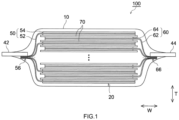
- FIG. 1 is a cross sectional view that schematically shows a configuration of a lithium ion secondary battery 100 in accordance with one embodiment.
- the lithium ion secondary battery 100 accommodates an electrode body 20 and a nonaqueous electrolyte (not shown) inside an outer package 10.
- One end of a positive electrode terminal 42 is electrically connected to a positive electrode 50 inside the outer package 10
- one end of a negative electrode terminal 44 is electrically connected to a negative electrode 60 inside the outer package 10.
- the other end of the positive electrode terminal 42 and the other end of the negative electrode terminal 44 are exposed toward the outside of the outer package 10.
- the outer package 10 is formed in a bag like shape with a laminate film.
- the outer package 10 includes an accommodation space that accommodates the electrode body 20 and the nonaqueous electrolyte at the inside, and the periphery of the accommodation space can be sealed with heat welding (heat sealing).
- the material configuring the laminate film is not particularly restricted, and typically a configured one in which a foil shaped metal and a resin sheet are pasted can be used.
- a laminate film including a three layers structure in which, on the surface of a cast polypropylene film (CPP) for the heat welding, a metal layer made of aluminum, or the like is provided for the purpose of adding the heat resistance, the seal strength, the shock resistance, or the like, and in which, further on the surface of this metal layer, an outside resin layer made of polyethylene terephthalate (PET), polyamide (PA), nylon film, or the like is provided.
- CPP cast polypropylene film
- PET polyethylene terephthalate
- PA polyamide
- nylon film or the like
- electrode sheets of the positive electrode 50 and negative electrode 60 are insulated through a separator 70 and a plurality of the resultant insulated sheets are laminated to configure the electrode body.
- the electrode sheets of the positive electrode 50 and negative electrode 60 each includes a rectangular-shaped wide surface, and the electrode sheets are laminated to have one wide surface be opposed to the other wide surface.
- the laminated direction of the electrode body 20 is the thickness direction T.
- the electrode sheet (positive electrode sheet) of the positive electrode 50 includes a sheet-shaped positive electrode current collector 52 that has a rectangular-shaped wide surface, and includes a positive electrode composite material layer 54 that is provided to coat the surface of the positive electrode current collector 52.
- a positive electrode current collector exposed part in which the positive electrode composite material layer 54 is not formed is provided on the edge part at one side in the width direction (W direction in FIG. 1 ) of the positive electrode current collector 52.
- Respective positive electrode current collector exposed parts of the laminated positive electrode sheets are joined in a bundle shape from the above-described laminate direction (T direction in FIG. 1 ) so as to form a positive electrode terminal join part 56.
- the electrode sheet (negative electrode sheet) of the negative electrode 60 includes a sheet-shaped negative electrode current collector 62 that has a rectangular-shaped wide surface, and includes a negative electrode composite material layer 64 that is provided to coat the surface of the negative electrode current collector 62.
- the edge part at one side of the negative electrode current collector 62 in the width direction (W direction in FIG. 1 ) is provided with a negative electrode current collector exposed part in which the negative electrode composite material layer 64 is not formed.
- Respective negative electrode current collector exposed parts of the laminated negative electrode sheets are joined in a bundle shape from the above-described laminate direction (T direction in FIG. 1 ) so as to form a negative electrode terminal join part 66.
- the positive electrode terminal 42 is a sheet-shaped conductive member, one end is joined to the positive electrode terminal join part 56 inside the outer package 10, and the other end is exposed toward the outside of the outer package 10.
- two laminate films are stacked one on another as to sandwich the positive electrode terminal 42 from the thickness direction T, and the laminate films are welded on the surface of the positive electrode terminal 42.
- a welding film made of resin might be intervened between the positive electrode terminal 42 and the laminate film.
- the negative electrode terminal 44 might be configured similarly to the above-described positive electrode terminal 42, except that the one end is joined to the negative electrode terminal join part 66.
- the positive electrode composite material layer 54 included by the positive electrode 50 includes a positive electrode active substance.
- a lithium composite metal oxide having a layer-shaped structure, a spinel structure, or the like for example, LiNi 1/3 Co 1/3 Mn 1/3 O 2 , LiNiO 2 , LiCoO 2 , LiFeO 2 , LiMn 2 O 4 , LiNi 0.5 Mn1.5O 4 , LiCrMnO 4 , LiFePO 4 , or the like
- LiNi 1/3 Co 1/3 Mn 1/3 O 2 , LiNiO 2 , LiCoO 2 , LiFeO 2 , LiMn 2 O 4 , LiNi 0.5 Mn1.5O 4 , LiCrMnO 4 , LiFePO 4 , or the like can be obtained.
- the positive electrode composite material layer 54 might include a conductive assistant agent, a dispersing agent, a binder, or the like.
- a conductive assistant agent for example, a carbon black such as acetylene black (AB), and the other carbon materials (graphite, or the like) can be suitably used.
- the dispersing agent for example, it is possible to use polyvinyl alcohol (PVA), or the like.
- PVA polyvinyl alcohol
- the binder for example, it is possible to use polyvinylidene fluoride (PVDF), or the like.
- the positive electrode composite material layer 54 can be formed by dispersing the positive electrode active substance and a material (conductive assistant agent, binder, or the like) used as needed into a suitable solvent (for example, N-methyl-2-pyrrolidone: NMP), by preparing the paste formed (or slurry formed) composition, by coating a suitable amount of this composition on the surface of the positive electrode current collector 52, and then by drying the resultant.
- a suitable solvent for example, N-methyl-2-pyrrolidone: NMP
- FIG. 2 is a cross section enlarged view that schematically shows a configuration of the negative electrode current collector 62. The detailed configuration of the negative electrode current collector 62 will be described later.
- the negative electrode composite material layer 64 is formed on the both surfaces of the negative electrode current collector 62 (see FIG. 1 ).
- the negative electrode composite material layer 64 includes a negative electrode active substance, and for example, it is possible to use a carbon material, such as graphite, hard carbon, and soft carbon, and a silicon material, such as Si and SiO, or the like.
- the negative electrode composite material layer 64 might further include a binder, a thickening agent, or the like.
- the binder for example, it is possible to use styrene butadiene rubber (SBR), or the like.
- SBR styrene butadiene rubber
- the thickening agent for example, it is possible to use carboxy methyl cellulose (CMC), or the like.
- the negative electrode composite material layer 64 can be formed by dispersing the negative electrode active substance and a material (binder, or the like) used as needed into a solvent (for example, ion exchange water), by preparing a paste formed (or slurry formed) composition, by coating a suitable amount of this composition on the surface of the negative electrode current collector 62, and then by drying the resultant.
- a solvent for example, ion exchange water
- the separator 70 it is possible to use various fine porous sheets similar to those conventionally used for the lithium ion secondary battery, for example, to obtain a fine porous resin sheet made of resin, such as polyethylene (PE) and polypropylene (PP).
- the fine porous resin sheet described above might be configured with a single layer structure, or might be configured with two layers or more multilayer structure (for example, a three layers structure in which PP layers are laminated on both surfaces of the PE layer).
- a heat resistant layer (HRL) might be provided on the surface of the separator 70.
- the nonaqueous electrolyte it is possible to use one similar to the conventional lithium ion secondary battery.
- a nonaqueous electrolyte that a supporting salt is contained in a nonaqueous solvent.
- an aprotic solvent such as carbonates, esters, and ethers.
- carbonates for example, ethylene carbonate (EC), diethyl carbonate (DEC), dimethyl carbonate (DMC), ethyl methyl carbonate (EMC), or the like.
- a fluorine type solvent of fluorinated carbonate such as monofluoroethylene carbonate (MFEC), difluoroethylene carbonate (DFEC), monofluoromethyl difluoromethyl carbonate (F-DMC), and trifluoro dimethyl carbonate (TFDMC).
- MFEC monofluoroethylene carbonate
- DFEC difluoroethylene carbonate
- F-DMC monofluoromethyl difluoromethyl carbonate
- TFDMC trifluoro dimethyl carbonate
- the nonaqueous solvents as described above one kind of them can be used alone, or 2 or more kinds of them can be combined so as to be used.
- the supporting salt for example, it is possible to suitably use a lithium salt, such as LiPF 6 , LiBF 4 , and LiClO 4 .
- the concentration of the supporting salt is approximately equal to or more than 0.7 mol/L and not more than 1.3 mol/L.
- the nonaqueous electrolyte might include a component other than the above-described nonaqueous solvent and supporting salt, and might include various additive agents, for example, a gas generation agent, a coating film forming agent, a dispersing agent, a thickening agent, or the like.
- a coating film forming agent such as lithium bis(oxalate)borate (LiBOB), vinylene carbonate (VC), vinyl ethylene carbonate (VEC), and fluoro ethylene carbonate (FEC); an overcharge additive agent that is consisted of a chemical compound capable of generating gas at the overcharge time and that is represented by an aromatic chemical compound, such as biphenyl (BP) and cyclohexylbenzene (CHB); a surface active agent; a dispersing agent; a thickening agent, an antifreezing agent, or the like.
- BP biphenyl
- CHB cyclohexylbenzene
- concentrations of these additive agents with respect to the whole of the nonaqueous electrolyte are, for example, equal to or less than 6 mass% (typically, 0.5 mass% to 4 mass%), although they would be different based on the kinds of the additive agents.
- the negative electrode current collector 62 includes a laminate structure in which a resin layer 62a, metal layers 62b, and resin coat layers 62c are laminated.
- metal layers 62b are formed on the both surfaces of the resin layer 62a, and the resin coat layers 62c are formed on the surfaces of the metal layers 62b.
- the resin layer 62a it is enough for the resin layer 62a to use a resin that induces the volume increase in response to the temperature rise at the time of inside short circuit, and the resin layer is configured with, for example, a thermoplastic resin.
- the resin layer is configured with, for example, a thermoplastic resin.
- the state of the thermoplastic resin is changed from the solid to the liquid and thus the volume is increased.
- Increasing the volume of the resin layer 62a described above induces adding the pressure on the metal layers 62b, and thus it is possible to break the metal layers 62b. Breaking the metal layers 62b induces drastic increase in the electric resistance, and thus it is possible to block the current inside the battery. Thus, it is possible to suppress the temperature rise of the battery at the time of inside short circuit.
- thermoplastic resin configuring the resin layer 62a it is preferable for the thermoplastic resin configuring the resin layer 62a to use a thermoplastic resin whose melting point is equal to or less than 265 °C at 1 atmosphere of pressure. It is possible for those having the property described above to obtain, for example, polyethylene terephthalate (PET), polyamide (PA), polyvinyl alcohol (PVA), polyethylene (PE), polypropylene (PP), poly styrene (PS), polyvinyl chloride (PVC), thermoplastic polyester, acrylonitrile-butadiene-styrene (ABS), acrylonitrile-styrene (AS), polymethyl methacrylate (PMMA), polyvinylidene fluoride (PVDF), polyvinylidene chloride (PVDC), or the like.
- PET polyethylene terephthalate
- PA polyamide
- PVA polyvinyl alcohol
- PE polyethylene
- PP polypropylene
- PS poly styren
- thermoplastic resin whose melting point is equal to or less than 200 °C at 1 atmosphere of pressure
- thermoplastic resin whose melting point is equal to or less than 200 °C at 1 atmosphere of pressure
- PVA, PE, PP, PVDF, or the like for example, PVA, PE, PP, PVDF, or the like.
- Making the resin layer 62a have a lower melting point can implement blocking the current inside the battery at a lower temperature when the inside short circuit is caused on the lithium ion secondary battery 100.
- the melting point of the resin configuring the resin layer 62a is too low, there are some fears that the resin layer 62a happens to melt even at the normal use time of the lithium ion secondary battery 100.
- the melting point of the resin configuring the resin layer 62a at 1 atmosphere of pressure is equal to or more than 90 °C, and for example, the melting point might be equal to or more than 100 °C.
- the thermoplastic resins one kind of them can be used alone, or 2 or more kinds of them can be used in combination.
- the melting point of the resin layer can be measured by a general differential scanning calorimetry (DSC).
- the resin layer 62a can include a conductive particle.
- Making the resin layer 62a include the conductive particle can improve the electric conductive property of the negative electrode current collector 62, and thus the electric resistance is further decreased.
- the conductive particles it is possible to use, for example, a carbon powder, an electric conductive metal powder, or the like.
- As the carbon powder it is possible to use a carbon powder, such as various carbon blacks (for example, acetylene black, furnace black, and Ketjen black), and a graphite powder.
- the electric conductive metal powder it is possible to use, for example, a copper powder, an aluminum powder, a nickel powder, or the like, and it is preferable to use an electric conductive metal powder configured with a metal, among them, the same as the metal configuring the metal layer 62b.
- the metal layer 62b is a copper foil
- the conductive particle one kind of them can be used alone, or 2 or more kinds of them can be used in combination.
- the average particle diameter is, for example, approximately 10 nm to 10 ⁇ m and it is preferable to be 20 nm to 5 ⁇ m.
- the wording "average particle diameter" in the present specification means an accumulation 50% particle diameter (D 50 ) on the particle size distribution of the volume reference obtained by the laser diffraction scattering method.
- the resin layer 62a can include an inorganic filler.
- the inorganic filler for example, it is possible to use an inorganic oxide or glass that has an insulating property. Making the resin layer 62a include the inorganic filler having the insulating property can decrease the electric resistance. It is estimated that this is induced by the inorganic filler which improves the ununiformity of the electron density capable of being generated in the metal layer 62b.
- the inorganic oxide for example, it is possible to use alumina (Al 2 O 3 ), magnesia (MgO), silica (SiO 2 ), titania (TiO 2 ), or the like.
- the inorganic filler With respect to the inorganic filler, one kind of them can be used alone, or 2 or more kinds of them can be used in combination.
- the shape of the inorganic filler might be, for example, a particle shape, a fiber shape, a sheet shape, a flake shape, or the like.
- the average particle diameter of the inorganic filler is not restricted particularly, the average particle diameter based on the laser diffraction scattering method is, for example, 0.1 ⁇ m to 10 ⁇ m, or might be 0.5 ⁇ m to 5 ⁇ m.
- the average thickness of the resin layer 62a is enough to be equal to or more than 0.1 ⁇ m, and it might be, for example, equal to or more than 10 ⁇ m. If the average thickness is as described above, the volume change occurs accompanying with the pressure that breaks the metal layer 62b when the resin layer 62a melts, and thus it is preferable. In addition, although not restricted particularly, the average thickness of the resin layer 62a is typically equal to or less than 80 ⁇ m, and might be, for example, equal to or less than 40 ⁇ m.
- the volume change at the time of melting is larger with the thickness of the resin layer 62a being larger, but from the perspective of implementing high capacity of the battery and implementing light weighting of the battery, it is not preferable to have the thickness larger than the required one.
- the thickness of the resin layer 62a can be, for example, measured by the scanning electron microscope (SEM) observation or the like.
- the metal layer 62b is a layer having the electric conductive property.
- the metal layer 62b can be configured with a metal foil conventionally used for the negative electrode current collector of the lithium ion secondary battery, and it is possible to use, for example, a metal foil of copper, alloy whose main component is copper, titanium, nickel, or the like.
- the alloy whose main component is copper means an alloy in which 50 wt% or more of the configuration component is copper.
- the negative electrode current collector 62 shown in FIG. 2 includes a rough surface part in which a plurality of protruding parts 62bl and a plurality of recessed parts 62b2 are provided on the surface of the metal layer 62b (surface at the side not opposed to the resin layer 62a), and the surface at the opposite side is a flat surface.
- a resin coat layer 62c is formed on the rough surface part, and a resin is accumulated on the recessed part 62b2.
- the plurality of protruding parts 62b1 includes an exposed part 62b3 that is exposed from the resin coat layer 62c.
- Making the metal layer 62b include the rough surface part can provide a comparatively thin thickness portion on the metal layer 62b, and thus it becomes easy to make the metal layer 62b be broken at the thin thickness portion of the metal layer 62b as the start point at the time of inside short circuit.
- including the exposed part 62b3 can increase the contact area of the negative electrode composite material layer 64, formed on the surface of the negative electrode current collector 62, with the negative electrode current collector 62, and thus it becomes hard to make the negative electrode composite material layer 64 be peeled off.
- the metal layer 62b can directly come into contact with the negative electrode composite material layer 64, and thus it is possible to secure a favorable conductive path so as to decrease the electric resistance.
- the arithmetic average roughness Ra of the rough surface part of the metal layer 62b is, for example, 0.5 ⁇ m to 15 ⁇ m, or might be 0.5 ⁇ m to 5 ⁇ m.
- the arithmetic average roughness Ra can be measured, for example, on the basis of JIS_B_0601:2001 with a probe type of surface roughness measurement device.
- the average value X ( ⁇ m) of the thickness x ( ⁇ m) of the thinnest portion of the metal layer 62b is, for example, equal to or more than 0.1 ⁇ m, preferably equal to or more than 0.5 ⁇ m, or more preferably equal to or more than 0.8 ⁇ m.
- the thinnest portion of the metal layer 62b becomes the broken start point at the time of inside short circuit, and thus it should be, for example, equal to or less than 5 ⁇ m, preferably equal to or less than 4 ⁇ m, or more preferably equal to or less than 3 ⁇ m.
- the average value Y ( ⁇ m) of the thickness y ( ⁇ m) of the thickest portion of the metal layer 62b is, for example, equal to or more than 1 ⁇ m, and might be equal to or more than 2 ⁇ m or equal to or more than 4 ⁇ m.
- the average value Y described above is, for example, equal to or less than 12 ⁇ m or might be equal to or less than 11 ⁇ m.
- the average value X ( ⁇ m) of the thickness x ( ⁇ m) of the thinnest portion of the metal layer 62b is equal to or more than 0.8 ⁇ m and not more than 3 ⁇ m (0.8 ⁇ m ⁇ X ⁇ 3 ⁇ m)
- the average value Y ( ⁇ m) of the thickness y ( ⁇ m) of the thickest portion of the metal layer 62b is equal to or more than 2 ⁇ m and not more than 11 ⁇ m (2 ⁇ m ⁇ Y ⁇ 11 ⁇ m) and X ⁇ Y
- the thickness x ( ⁇ m) of the thinnest portion and the thickness y ( ⁇ m) of the thickest portion of the metal layer 62b can be measured on the basis of the cross section SEM images of the metal layer 62b along the laminate direction of the resin layer 62a and metal layer 62b (T direction in FIG. 2 ).
- a predetermined magnification for example, magnification: 4000 times
- n-number of the above-described cross section SEM images, respectively having different points of view, are obtained (n is a natural number at least equal to or more than 4, for example, equal to or more than 10).
- the thickness x ( ⁇ m) of the thinnest portion and the thickness y ( ⁇ m) of the thickest portion of the metal layer 62b are measured so as to be able to obtain the average value X ( ⁇ m) of the above-described x and the average value Y ( ⁇ m) of the above-described y.
- the thickness x of the above-described thinnest portion typically exists at the position of the recessed part
- the thickness y of the above-described the thickest portion typically exists at the position of the protruding part.
- the distance between the adjacent protruding parts 62bl is not restricted particularly, it is preferable that the distance is equal to or less than 1 ⁇ m. This increases the number of the protruding parts 62b1, so as to increase the surface area of the metal layer 62b. As this result, the contact area of the metal layer 62b with the negative electrode composite material layer 64 is increased, the negative electrode composite material layer 64 becomes hard to be peeled off, and thus the capacity retention rate is improved.
- distance between the protruding parts 62b1 means a distance between the respective highest portions of adjacent protruding parts 62b1 on the cross section SEM image along the laminate direction (thickness direction T) of the resin layer 62a and metal layer 62b.
- the rough surface part of the metal layer 62b can be formed by a well known roughen processing method, and it is possible to use, for example, laser irradiation, etching, sputtering, ion plating, PLD (Pulsed Laser Deposition), or the like. Among them, it is preferable to form by using the etching processing with a drug solution. If the etching processing is used, it is possible to make the formed distance between the protruding parts 62bl be shorter, and for example, it is possible to be equal to or less than 1 ⁇ m.
- the resin coat layer 62c is formed on the rough surface part of the metal layer 62b. More particularly, the resin coat layer 62c is mainly formed within the recessed part 62b2, and covers at least one part of the protruding part 62b1. In addition, some among a plurality of protruding parts 62b1 might have the whole portion of the protruding part 62b1 be covered with the resin coat layer 62c (in other words, a protruding part 62bl not including the exposed part 62b3 might exist).
- the resin coat layer 62c has a function as a binder that firmly adheres the negative electrode composite material layer 64 with the negative electrode current collector 62, and it is possible to further inhibit the negative electrode composite material layer 64 from being peeled off. Particularly, under the low temperature condition, the resin coat layer 62c is shrunk to closely bond the negative electrode composite material layer 64 to the negative electrode current collector 62, so as to be able to further decrease the electric resistance. In addition, the resin coat layer 62c melts in response to the temperature rise at the time of inside short circuit, and thus it is possible to apply the pressure on the recessed part 62b2 of the metal layer 62b. Thus, at the time of inside short circuit, the metal layer 62b suffers pressure from the both sides of the resin layer 62a and resin coat layer 62c, and therefore it is possible to surely break the metal layer 62b.
- the kinds of resin configuring the resin coat layer 62c might be the same as the illustrations of the resin capable of configuring the resin layer 62a.
- the suitable example it is possible to obtain a resin conventionally used as the binder of the composite material layer, and it is possible to suitably use, for example, PVDF.
- the negative electrode composite material layer 64 it is possible to suitably inhibit the negative electrode composite material layer 64 from being peeled off.
- the resin coat layer 62c and the resin layer 62a might be configured with the same resin or might be configured with the different resin, it is preferable that the difference between the melting point of the resin configuring the resin layer 62a and the melting point of the resin configuring the resin coat layer 62c is smaller.
- the difference of melting points described above is equal to or less than 100 °C, and more preferable that it is equal to or less than 50 °C.
- the timing of melting the resin layer 62a and the timing of melting the resin coat layer 62c at the time of inside short circuit become closer to each other, so as to facilitate making the metal layer 62b be broken.
- the resin coat layer 62c includes a conductive particle.
- the conductive particle it is possible to use the above-described one capable of being used for the resin layer 62a.
- the existence rate of the protruding parts 62b1 each including the exposed part 62b3 is higher.
- the rate of the protruding parts 62b 1 each including the exposed part 62b3 with respect to the number of the whole of the plurality of protruding parts 62bl is preferably equal to or more than 20 number%, more preferably equal to or more than 30 number%, further preferably equal to or more than 50 number%, and moreover preferably equal to or more than 80 number%, or might be, for example, 100 number%.
- the protruding part 62b1 including the exposed part 62b3 includes the exposed part 62b3 and a portion covered by the resin coat layer 62c, and then the contact area of the metal layer 62b with the negative electrode composite material layer 64 becomes too small in the case where the occupation rate of the exposed part 62b3 is too low. Thus, it is possible that the negative electrode composite material layer 64 becomes to be easily peeled off and the electric resistance is increased. Therefore, in the height direction of the protruding part 62b1 (thickness direction T in FIG.
- the average value of the occupation rate of the height T3 of the exposed part 62b3 with respect to the height T1 of the protruding part 62bl is, for example, preferably equal to or more than 5%, might be more preferably equal to or more than 10%, or for example, might be equal to or more than 30%.
- the occupation rate of the exposed part 62b3 is too high, the thickness of the formed resin coat layer 62c becomes insufficient and thus the effect of the resin coat layer 62c becomes insufficient.
- the average value of the occupation rate of the height T3 of the exposed part 62b3 with respect to the height T1 of the protruding part 62b1 is, for example, preferably equal to or less than 99%, is more preferably equal to or less than 95%, or might be equal to or less than 90%.
- the occupation rate of the exposed part 62b3 can be measured on the basis of cross section SEM images along the laminate direction of the resin layer 62a and metal layer 62b.
- m-number of protruding parts 62bl each including the exposed part 62b3 are selected at random (m is a natural number equal to or more than 5), and the average value of the occupation rates of the exposed parts 62b3 of the selected protruding parts 62b1 is obtained.
- the measurement methods for the height T1 of the protruding part 62b1, the thickness T2 of the resin coat layer 62c, and the height T3 of the exposed part 62b3 might be similar to the above-described measurement method for the thickness of the metal layer 62b, and the measurements can be performed on the basis of the cross section SEM images along the laminate direction of the resin layer 62a and metal layer 62b.
- the height T1 of the protruding part 62bl can be obtained by obtaining an intersection point with a line that connects the lowest points (portions whose heights are the lowest) one another of the recessed parts 62b2 adjacently arranged at the left and right sides of the protruding part 62bl and with a line drawn from the apex of the protruding part 62bl (the highest point) toward the laminate direction on the above-described cross section SEM image, and by measuring the distance between the apex of the protruding part 62b 1 and the intersection point.
- the rough surface part of the metal layer 62b and the resin coat layer 62c are provided on the whole of the region on which the negative electrode composite material layer 64 is formed. This can make the whole of the negative electrode composite material layer 64 be hardly peeled off from the negative electrode current collector 62. In addition, the breakage of the metal layer 62b can be induced promptly if the inside short circuit is caused at any position of the negative electrode composite material layer 64, and thus the higher safety property can be implemented.
- either of the resin layer 62a and resin coat layer 62c is not formed on the negative electrode terminal join part 66. This can make the negative electrode terminal join part 66 directly join the metal layers 62b one another of the plurality of negative electrode sheets, and thus it is possible to make the negative electrode terminal join part 66 have the outstanding electric conductive property and the outstanding join strength.
- FIG. 3 is an enlarged cross sectional view schematically shows a configuration of the modified example of the negative electrode current collector 62.
- the rough surface part is provided even on the interface of the metal layer 62b and resin layer 62a. This can increase the contact area of the resin layer 62a with the metal layer 62b, and thus it is possible to make the metal layer 62b be adhered more firmly to the resin layer 62a.
- the thickness y ( ⁇ m) at the thickest portion of the metal layer 62b the thickness including the protruding parts existing on the surfaces at the both sides of the metal layer 62b is measured as shown in FIG. 3 .
- the lithium ion secondary battery 100 can be used for various purposes. For example, it is possible to suitably use it as a high output power source for a motor mounted on a vehicle (power supply for drive). Although the kinds of the vehicle is not restricted particularly, the vehicle is typically an automobile, for example, plug-in hybrid electric vehicle (PHEV), hybrid electric vehicle (HEV), battery electric vehicle (BEV), or the like.
- PHEV plug-in hybrid electric vehicle
- HEV hybrid electric vehicle
- BEV battery electric vehicle
- the lithium ion secondary battery 100 can be used in a battery pack form in which a plurality of batteries are electrically connected.
- the current collector herein disclosed can be used as the positive electrode current collector 52, too. In this case, it is enough to change the metal foil configuring the metal layer 62b to a metal foil (for example, aluminum foil) used for the positive electrode, and the other configurations might be similar.
- a wound electrode body might be provided in which a positive electrode sheet and a negative electrode sheet are wound via a separator sheet.
- a battery case might be used that is configured with a metal material, such as aluminum.
- it might be an all-solid battery using a solid electrolyte as the electrolyte, or might be a polymer battery using a polymer electrolyte as the electrolyte.
- the copper foil welded on the manufactured resin sheet described above was soaked in a mix liquid in which a conductive particle, PVDF, and N-methyl-2-pyrrolidone (NMP) were mixed, so as to perform the dip-coating on the copper foil surface. Then, this copper foil was dried, so as to form the resin coat layer on the surface of the copper foil. Then, this resin coat layer was scraped with a brush at the speed of 200 rpm to adjust the thickness of the resin coat layer, so as to manufacture the negative electrode current collector of each example. Incidentally, in the example with the resin coat layer including the conductive particle, acetylene black (AB) or copper (Cu) particles was used as the conductive particle.
- AB acetylene black
- Cu copper
- the kind of the conductive particle used in each example is shown in Table 1. Additionally, in the examples 7 to 9, a resin sheet including at least one among AB as the conductive particle and alumina (Al 2 O 3 ) powder as the inorganic filler was used. The kind of the inorganic filler used in each example is shown in Table 1.
- a powder of silicon oxide and a graphite were mixed at the weight ratio of 80:20, and the resultant was prepared as the negative electrode active substance.
- SBR styrene butadiene rubber
- CMC carboxy methyl cellulose
- the paste for forming the negative electrode composite material layer was prepared.
- a die coater was used to add the paste for forming the negative electrode composite material layer in a strip-like shape so as to coat the copper foil surfaces at the both surfaces of the negative electrode current collector of each example prepared as described above, and then the resultant was dried. Incidentally, this operation was performed on the both surfaces of the negative electrode current collector of each example. Then, the press processing was performed on this negative electrode current collector so as to manufacture the negative electrode sheet.
- a powder of LiNi 1/3 Co 1/3 Mn 1/3 O 2 (NCM) was prepared as the positive electrode active substance
- acetylene black (AB) was prepared as the conductive assistant agent
- PVDF polyvinylidene fluoride
- PVA polyvinyl alcohol
- NMP being the dispersion medium was added to have the solid content be 56 mass%, and then the resultant was mixed with the planetary mixer.
- the paste for forming the positive electrode composite material layer was prepared.
- a die coater was used to add the paste for forming the positive electrode composite material layer in a strip-like shape so as to coat the both surfaces of the aluminum foil, and then the resultant was dried. Then, the press processing was performed on the aluminum foil including the dried paste for forming the positive electrode composite material layer so as to manufacture the positive electrode sheet.
- a porous polyolefin sheet was prepared that included a three layers structure of PP/PE/PP.
- the manufactured positive electrode sheet and negative electrode sheet were opposed to each other through the separator sheet to be laminated, so as to manufacture the laminate type electrode body.
- An terminal was attached to the laminate type electrode body, and then the laminate type electrode body was accommodated in the aluminum laminate bag. Then, the laminate electrode body is impregnated with the nonaqueous electrolyte and then the opening of the aluminum laminate bag was encapsulated and sealed so as to manufacture the lithium ion secondary battery for evaluation.
- the nonaqueous electrolyte As for the nonaqueous electrolyte, the ethylene carbonate (EC) and ethyl methyl carbonate (EMC) were mixed at the volume ratio of 1:3, further vinylene carbonate (VC) at 2 mass% was added to the mixture, LiPF 6 as the supporting salt at the concentration of 1.0 mol/L was dissolved into the mix solvent, and then the resultant was used.
- EC ethylene carbonate
- EMC ethyl methyl carbonate
- VC vinylene carbonate
- the cross sections of the manufactured negative electrode current collectors of examples 3 to 11 in the laminate direction of the resin layer of the negative electrode current collector and the copper foil was observed at 4000 times of magnification with SEM, and cross section SEM images for 4 positions with different points of view were obtained. On each of the obtained cross section SEM images, the minimum thickness x and maximum thickness y of the copper foil were measured. Incidentally, since each example included the copper foils on the both surfaces of the resin layer, on each point of view, the minimum thickness x and maximum thickness y of each copper foil were measured.
- values of the minimum thickness x and maximum thickness y respectively obtained from the cross section SEM images at the above-described 4 positions with different points of view were used to obtain the average value X ( ⁇ m) of the minimum thickness and the average value Y ( ⁇ m) of the maximum thickness of the copper foil of each example. These values are respectively shown as “average minimum thickness X ( ⁇ m)” and “average maximum thickness Y ( ⁇ m)” in Table 1. Incidentally, regarding the example 1 and the example 2, the measured value of the thickness of the copper foil is shown.
- the number of protruding parts existing on the surface at the side of the copper foil where the resin coat layer was formed from each point of view was counted, and among them, the number of protruding parts, in which the protruding part height equal to or more than 5% was exposed from the resin coat layer, was measured. Then, the rate of the number of the protruding parts exposed from the resin coat layer described above is shown in Table 1 as "rate of protruding parts including exposed part (number%)".
- Each of the above-described manufactured lithium ion secondary batteries for evaluation was disposed under a 25 °C environment.
- Each lithium ion secondary battery for evaluation was subjected to the constant current charging with 1/3 C current value until it reached 4.2 V, and then subjected to the constant voltage charging until the current value became 1/50 C, so as to reach the full charging state.
- each lithium ion secondary battery for evaluation was subjected to the constant current electric discharging with 1/3 C current value until it reached 3.0 V.
- the electric discharging capacity at that time was treated as the initial capacity.
- the wording "1 C" means a current size that can implement charging of SOC (state of charge) from 0% to 100% for 1 hour.
- Each of the above-described activated lithium ion secondary batteries for evaluation was adjusted to have 3.70 V release voltage, and was disposed under a -5 °C temperature environment. Under the environment described above, the electric discharging with 3 C current value for 25 seconds was performed, and then the voltage change amount ⁇ V at that time was obtained. In addition, the current value to be 20 C was obtained. Then, the calculated value of ( ⁇ V/20 C current value) was obtained as the low temperature resistance.
- the ratio of the low temperature resistance of the lithium ion secondary battery for evaluation of each example in the case where the low temperature resistance of the lithium ion secondary battery for evaluation of the example 1 is set to be 1.00 is shown as the standardization low temperature resistance in Table 1.
- Each of the activated lithium ion secondary batteries for evaluation was adjusted to have the release voltage be 3.3 V, and was disposed under the 25 °C environment.
- a constant current system was applied for the electric charging and discharging, the charging was performed with 1 C current value until it reached 4.2 V, and then the electric discharging was performed with 1 C current value until it reached 3.3 V This electric charging and discharging was treated as 1 cycle, and then 500 cycles were performed repeatedly. Then, the capacity after 500 cycles was measured by the method similar to the above-described initial capacity. Then, a value of (capacity after 500 cycles/initial capacity) ⁇ 100 was calculated, so as to obtain the capacity retention rate (%). The results are shown in Table 1.
- each lithium ion secondary battery for evaluation was subjected to the constant current charging with 1/3 C current value until it reached 4.2 V, the constant voltage charging was performed until the current value reached 1/10 C, so as to reach the full charging state.
- each lithium ion secondary battery for evaluation at the full charging state was disposed under 25 °C environment.
- a steel nail whose diameter was 3 mm was made to penetrate a portion near the center of each lithium ion secondary battery for evaluation at 10 mm/sec speed.
- the outer surface temperature of each lithium ion secondary battery for evaluation at that time was measured with a thermocouple, so as to measure the highest temperature.
- the examples 3 to 11 had more favorable results of the safety property test, and improved the capacity retention rate, too. Further, in addition to this, the examples 3 to 11 had the low temperature resistance that was lower than the example 1. This shows that, when the current collector including the resin layer, the metal foil having the rough surface part, and the resin coat layer is used, not only the outstanding safety property is provided but also the improvement of the battery performance is implemented, such as the improvement of the capacity retention rate and the decrease in the low temperature resistance.
- the resin layer includes the conductive particle and/or the inorganic filler, the improvement of the capacity retention rate and the decrease in the low temperature resistance are implemented at the particularly higher level.
- test example 2 discussion was performed about the thickness of the resin coat layer. Particularly, attention was paid to the protruding part that includes the exposed part exposed from the resin coat layer, and the occupation rate of the exposed part on the protruding part was studied.
- 8 kinds of negative electrode current collectors, examples 12 to 19, were manufactured and were subjected to the test. After manufactured similarly to the example 5 in the above-described test example 1, these negative electrode current collectors were subjected to the adjustment on the scraped rate of the resin coat layer of each example with a brush, so as to manufacture the resin coat layers having various thicknesses. Then, the lithium ion secondary battery for evaluation was manufactured similarly to the test example 1, and the various evaluation tests were performed similarly to the test example 1.
- the study was performed about the ranges of the average minimum thickness X and average maximum thickness Y of the used copper foil.
- the etching processing was performed on the used copper foil, a plurality of copper foils in which the extents of the rough surface parts were different were prepared, and these were used to manufacture the negative electrode current collectors of examples 20 to 26.
- the configuration other than the copper foil was similar to the above-described example 5, the lithium ion secondary battery for evaluation for each example was manufactured. Then, various evaluation tests were performed similarly to the above-described test example 1. The results are shown in Table 3.
- any of the example 5 and the examples 20 to 26 implemented the outstanding safety property and had the outstanding capacity retention rate and the outstanding low temperature resistance.
- the example 5 and the examples 24 to 26 implemented the particularly outstanding capacity retention rate and the particularly outstanding low temperature resistance. Based on this, it can be understood that the average minimum thickness X of the metal layer being equal to or more than 0.8 ⁇ m and not more than 3 ⁇ m and the average maximum thickness Y of the metal layer being equal to or more than 2 ⁇ m and not more than 11 ⁇ m are suitable.
Landscapes
- Chemical & Material Sciences (AREA)
- Engineering & Computer Science (AREA)
- Chemical Kinetics & Catalysis (AREA)
- Electrochemistry (AREA)
- General Chemical & Material Sciences (AREA)
- Materials Engineering (AREA)
- Composite Materials (AREA)
- Manufacturing & Machinery (AREA)
- Cell Electrode Carriers And Collectors (AREA)
Claims (9)
- Stromabnehmer, der für eine Elektrode einer Sekundärbatterie verwendet wird, aufweisend:eine Laminatstruktur, in der eine Harzschicht (62a) und eine Metallschicht (62b), die auf beiden Oberflächen der Harzschicht (62a) gebildet ist, laminiert sind, wobeieine Oberfläche der Metallschicht (62b) einen rauen Oberflächenteil aufweist, der über eine Mehrzahl an hervorstehenden Teilen (62b 1) und eine Mehrzahl an vertieften Teilen (62b2) verfügt,auf dem rauen Oberflächenteil eine Harzbeschichtungsschicht (62c) gebildet ist, undunter der Mehrzahl an hervorstehenden Teile (62b1) zumindest ein Teil der hervorstehenden Teile (62b 1) einen freiliegenden Teil (62b3) aufweist, der von der Harzbeschichtungsschicht (62c) aus freiliegt.
- Stromabnehmer nach Anspruch 1, wobei
eine Rate des hervorstehenden Teils (62b 1), der den freiliegenden Teil (62b3) aufweist, gleich oder mehr als 20 % der Mehrzahl an hervorstehenden Teilen (62b 1) beträgt. - Stromabnehmer nach Anspruch 1 oder 2, wobei
bei den hervorstehenden Teilen (62b 1), die den freiliegenden Teil (62b3) aufweisen, ein Durchschnittswert des Besetzungsgrads des freiliegenden Teils (62b3) in Bezug auf eine Höhenrichtung des hervorstehenden Teils (62b1) gleich oder mehr als 5 % und nicht mehr als 99 % beträgt. - Stromabnehmer nach Anspruch 3, wobei
der Durchschnittswert des Besetzungsgrads des freiliegenden Teils (62b3) 95 % oder weniger beträgt. - Stromabnehmer nach einem der Ansprüche 1 bis 4, wobei
wenn eine n-Anzahl an SEM-Bildern, die jeweils unterschiedliche Blickrichtungen haben, des Querschnitts des Stromabnehmers entlang einer Laminatrichtung der Harzschicht (62a) und der Metallschicht (62b) (n ist eine natürliche Zahl, die gleich oder größer als 4 ist) erhalten werden, ein Durchschnittswert X (µm) der Dicke x des dünnsten Abschnitts und ein Durchschnittswert Y (µm) der Dicke y des dicksten Abschnitts der Metallschicht (62b), die jeweils auf den SEM-Bildern beobachtet werden, folgende Bedingung erfüllen:
- Stromabnehmer nach einem der Ansprüche 1 bis 5, wobei
die Harzbeschichtungsschicht (62c) einen leitenden Partikel aufweist. - Stromabnehmer nach einem der Ansprüche 1 bis 6, wobei
die Harzschicht (62a) einen leitenden Partikel aufweist. - Stromabnehmer nach einem der Ansprüche 1 bis 7, wobei
die Harzschicht (62a) ein anorganisches Füllmaterial aufweist. - Sekundärbatterie, aufweisend:eine Positivelektrode (50) und eine Negativelektrode (60), wobeizumindest eine von der Positivelektrode (50) und der Negativelektrode (60) den Stromabnehmer nach einem der Ansprüche 1 bis 8 aufweist.
Applications Claiming Priority (1)
| Application Number | Priority Date | Filing Date | Title |
|---|---|---|---|
| JP2021082564A JP7377831B2 (ja) | 2021-05-14 | 2021-05-14 | 二次電池の集電体および二次電池 |
Publications (2)
| Publication Number | Publication Date |
|---|---|
| EP4123763A1 EP4123763A1 (de) | 2023-01-25 |
| EP4123763B1 true EP4123763B1 (de) | 2023-10-18 |
Family
ID=81580143
Family Applications (1)
| Application Number | Title | Priority Date | Filing Date |
|---|---|---|---|
| EP22171428.0A Active EP4123763B1 (de) | 2021-05-14 | 2022-05-03 | Stromsammler für sekundärbatterie und sekundärbatterie |
Country Status (5)
| Country | Link |
|---|---|
| US (1) | US12237514B2 (de) |
| EP (1) | EP4123763B1 (de) |
| JP (1) | JP7377831B2 (de) |
| KR (1) | KR102765071B1 (de) |
| CN (1) | CN115347194B (de) |
Families Citing this family (6)
| Publication number | Priority date | Publication date | Assignee | Title |
|---|---|---|---|---|
| KR102569103B1 (ko) | 2020-11-18 | 2023-08-23 | 주식회사 유앤에스에너지 | 전극용 집전체 |
| JP7285819B2 (ja) * | 2020-12-24 | 2023-06-02 | プライムプラネットエナジー&ソリューションズ株式会社 | 非水電解質二次電池 |
| JPWO2024204382A1 (de) * | 2023-03-30 | 2024-10-03 | ||
| JPWO2024252474A1 (de) * | 2023-06-05 | 2024-12-12 | ||
| KR20250019364A (ko) * | 2023-08-01 | 2025-02-10 | 주식회사 엘지에너지솔루션 | 전극 제조 장치 및 전극 제조 방법 |
| WO2026053310A1 (ja) * | 2024-09-04 | 2026-03-12 | 日産自動車株式会社 | 二次電池用集電体及び二次電池セル |
Family Cites Families (16)
| Publication number | Priority date | Publication date | Assignee | Title |
|---|---|---|---|---|
| JP3696790B2 (ja) * | 1999-01-14 | 2005-09-21 | 富士通株式会社 | リチウム二次電池 |
| KR100485091B1 (ko) * | 2002-10-25 | 2005-04-22 | 삼성에스디아이 주식회사 | 리튬 이차 전지용 음극 및 이를 포함하는 리튬 이차 전지 |
| US20050048369A1 (en) * | 2003-08-28 | 2005-03-03 | Matsushita Electric Industrial Co., Ltd. | Negative electrode for non-aqueous electrolyte secondary battery, production method thereof and non-aqueous electrolyte secondary battery |
| KR20060061282A (ko) * | 2005-02-28 | 2006-06-07 | 도요 고한 가부시키가이샤 | 복합 집전체 |
| JP4967267B2 (ja) * | 2005-07-19 | 2012-07-04 | パナソニック株式会社 | リチウムイオン電池用積層金属箔およびそれを用いたリチウムイオン電池 |
| JP2008171788A (ja) * | 2006-12-15 | 2008-07-24 | Hitachi Cable Ltd | リチウムイオン電池用集電体及びその製造方法 |
| WO2009119093A1 (ja) * | 2008-03-26 | 2009-10-01 | パナソニック株式会社 | リチウム二次電池用電極およびその製造方法 |
| JP5690529B2 (ja) * | 2010-08-25 | 2015-03-25 | シャープ株式会社 | 非水系二次電池用の集電体及び電極、並びに非水系二次電池 |
| US20140162122A1 (en) * | 2011-07-29 | 2014-06-12 | Uacj Foil Corporation | Collector and electrode structure, non-aqueous electrolyte cell, electrical double layer capacitor, lithium ion capacitor, or electricity storage component using same |
| CN106797046B (zh) * | 2014-08-25 | 2020-12-01 | 日产自动车株式会社 | 叠层型电池及其制造方法 |
| JP2016126901A (ja) * | 2014-12-26 | 2016-07-11 | トヨタ自動車株式会社 | 二次電池 |
| JP6222528B2 (ja) * | 2015-05-13 | 2017-11-01 | トヨタ自動車株式会社 | 非水電解液二次電池 |
| KR20170045800A (ko) * | 2015-10-20 | 2017-04-28 | 주식회사 엘지화학 | 고분자 수지층을 포함하는 이차전지용 전극 집전체 |
| TW201826607A (zh) * | 2016-09-08 | 2018-07-16 | 日商麥克賽爾控股股份有限公司 | 鋰離子二次電池及其製造方法 |
| CN108281662B (zh) * | 2017-01-12 | 2020-05-05 | 宁德时代新能源科技股份有限公司 | 一种集流体,其极片和电池及应用 |
| JP6848645B2 (ja) * | 2017-04-21 | 2021-03-24 | トヨタ自動車株式会社 | 集電積層体 |
-
2021
- 2021-05-14 JP JP2021082564A patent/JP7377831B2/ja active Active
-
2022
- 2022-05-03 EP EP22171428.0A patent/EP4123763B1/de active Active
- 2022-05-05 US US17/662,134 patent/US12237514B2/en active Active
- 2022-05-11 KR KR1020220057626A patent/KR102765071B1/ko active Active
- 2022-05-12 CN CN202210513631.8A patent/CN115347194B/zh active Active
Also Published As
| Publication number | Publication date |
|---|---|
| CN115347194A (zh) | 2022-11-15 |
| JP7377831B2 (ja) | 2023-11-10 |
| US20220367879A1 (en) | 2022-11-17 |
| KR20220155216A (ko) | 2022-11-22 |
| KR102765071B1 (ko) | 2025-02-11 |
| EP4123763A1 (de) | 2023-01-25 |
| JP2022175835A (ja) | 2022-11-25 |
| CN115347194B (zh) | 2025-10-14 |
| US12237514B2 (en) | 2025-02-25 |
Similar Documents
| Publication | Publication Date | Title |
|---|---|---|
| EP4123763B1 (de) | Stromsammler für sekundärbatterie und sekundärbatterie | |
| US12166196B2 (en) | Non-aqueous electrolyte secondary battery | |
| KR100788073B1 (ko) | 전지팩 및 차량 | |
| US11522199B2 (en) | Non-aqueous electrolyte secondary battery | |
| KR100749198B1 (ko) | 비수전해질 전지, 전지 팩 및 자동차 | |
| US20210159505A1 (en) | Non-aqueous electrolyte secondary battery | |
| KR101529408B1 (ko) | 비수 전해질 2차 전지 | |
| US10026941B2 (en) | Separator for nonaqueous electrolyte secondary battery, and battery including same | |
| KR101793849B1 (ko) | 비수전해질 이차 전지 및 조전지 | |
| EP2980885B1 (de) | Sekundärbatterie mit wasserfreiem elektrolyt | |
| EP2862219B1 (de) | Sekundärbatterie | |
| EP2731169A1 (de) | Sekundärbatterie | |
| CN107078280A (zh) | 非水电解质二次电池 | |
| JP7085149B2 (ja) | 非水電解質二次電池 | |
| EP2983235B1 (de) | Sekundärbatterie mit wasserfreiem elektrolyt | |
| JP4586357B2 (ja) | リチウムイオン電池 | |
| JP7285819B2 (ja) | 非水電解質二次電池 | |
| JP2014120214A (ja) | 非水電解液二次電池 | |
| JP2016015245A (ja) | リチウムイオン二次電池 | |
| EP4407702A1 (de) | Sekundärbatterie mit nichtwässrigem elektrolyten | |
| JP7731924B2 (ja) | 非水電解液二次電池 |
Legal Events
| Date | Code | Title | Description |
|---|---|---|---|
| PUAI | Public reference made under article 153(3) epc to a published international application that has entered the european phase |
Free format text: ORIGINAL CODE: 0009012 |
|
| STAA | Information on the status of an ep patent application or granted ep patent |
Free format text: STATUS: REQUEST FOR EXAMINATION WAS MADE |
|
| 17P | Request for examination filed |
Effective date: 20220503 |
|
| AK | Designated contracting states |
Kind code of ref document: A1 Designated state(s): AL AT BE BG CH CY CZ DE DK EE ES FI FR GB GR HR HU IE IS IT LI LT LU LV MC MK MT NL NO PL PT RO RS SE SI SK SM TR |
|
| GRAP | Despatch of communication of intention to grant a patent |
Free format text: ORIGINAL CODE: EPIDOSNIGR1 |
|
| STAA | Information on the status of an ep patent application or granted ep patent |
Free format text: STATUS: GRANT OF PATENT IS INTENDED |
|
| RIC1 | Information provided on ipc code assigned before grant |
Ipc: H01M 10/0525 20100101ALN20230331BHEP Ipc: H01M 10/42 20060101ALI20230331BHEP Ipc: H01M 4/70 20060101ALI20230331BHEP Ipc: H01M 4/62 20060101ALI20230331BHEP Ipc: H01M 4/66 20060101AFI20230331BHEP |
|
| INTG | Intention to grant announced |
Effective date: 20230428 |
|
| P01 | Opt-out of the competence of the unified patent court (upc) registered |
Effective date: 20230512 |
|
| GRAS | Grant fee paid |
Free format text: ORIGINAL CODE: EPIDOSNIGR3 |
|
| GRAA | (expected) grant |
Free format text: ORIGINAL CODE: 0009210 |
|
| STAA | Information on the status of an ep patent application or granted ep patent |
Free format text: STATUS: THE PATENT HAS BEEN GRANTED |
|
| RIN1 | Information on inventor provided before grant (corrected) |
Inventor name: SHINDO, YOHEI Inventor name: HORIKAWA, DAISUKE |
|
| AK | Designated contracting states |
Kind code of ref document: B1 Designated state(s): AL AT BE BG CH CY CZ DE DK EE ES FI FR GB GR HR HU IE IS IT LI LT LU LV MC MK MT NL NO PL PT RO RS SE SI SK SM TR |
|
| REG | Reference to a national code |
Ref country code: GB Ref legal event code: FG4D |
|
| REG | Reference to a national code |
Ref country code: CH Ref legal event code: EP |
|
| REG | Reference to a national code |
Ref country code: IE Ref legal event code: FG4D |
|
| REG | Reference to a national code |
Ref country code: DE Ref legal event code: R096 Ref document number: 602022000706 Country of ref document: DE |
|
| REG | Reference to a national code |
Ref country code: LT Ref legal event code: MG9D |
|
| REG | Reference to a national code |
Ref country code: NL Ref legal event code: MP Effective date: 20231018 |
|
| REG | Reference to a national code |
Ref country code: AT Ref legal event code: MK05 Ref document number: 1623265 Country of ref document: AT Kind code of ref document: T Effective date: 20231018 |
|
| PG25 | Lapsed in a contracting state [announced via postgrant information from national office to epo] |
Ref country code: NL Free format text: LAPSE BECAUSE OF FAILURE TO SUBMIT A TRANSLATION OF THE DESCRIPTION OR TO PAY THE FEE WITHIN THE PRESCRIBED TIME-LIMIT Effective date: 20231018 |
|
| PG25 | Lapsed in a contracting state [announced via postgrant information from national office to epo] |
Ref country code: GR Free format text: LAPSE BECAUSE OF FAILURE TO SUBMIT A TRANSLATION OF THE DESCRIPTION OR TO PAY THE FEE WITHIN THE PRESCRIBED TIME-LIMIT Effective date: 20240119 |
|
| PG25 | Lapsed in a contracting state [announced via postgrant information from national office to epo] |
Ref country code: IS Free format text: LAPSE BECAUSE OF FAILURE TO SUBMIT A TRANSLATION OF THE DESCRIPTION OR TO PAY THE FEE WITHIN THE PRESCRIBED TIME-LIMIT Effective date: 20240218 |
|
| PG25 | Lapsed in a contracting state [announced via postgrant information from national office to epo] |
Ref country code: LT Free format text: LAPSE BECAUSE OF FAILURE TO SUBMIT A TRANSLATION OF THE DESCRIPTION OR TO PAY THE FEE WITHIN THE PRESCRIBED TIME-LIMIT Effective date: 20231018 |
|
| PG25 | Lapsed in a contracting state [announced via postgrant information from national office to epo] |
Ref country code: AT Free format text: LAPSE BECAUSE OF FAILURE TO SUBMIT A TRANSLATION OF THE DESCRIPTION OR TO PAY THE FEE WITHIN THE PRESCRIBED TIME-LIMIT Effective date: 20231018 |
|
| PG25 | Lapsed in a contracting state [announced via postgrant information from national office to epo] |
Ref country code: ES Free format text: LAPSE BECAUSE OF FAILURE TO SUBMIT A TRANSLATION OF THE DESCRIPTION OR TO PAY THE FEE WITHIN THE PRESCRIBED TIME-LIMIT Effective date: 20231018 |
|
| PG25 | Lapsed in a contracting state [announced via postgrant information from national office to epo] |
Ref country code: LT Free format text: LAPSE BECAUSE OF FAILURE TO SUBMIT A TRANSLATION OF THE DESCRIPTION OR TO PAY THE FEE WITHIN THE PRESCRIBED TIME-LIMIT Effective date: 20231018 Ref country code: IS Free format text: LAPSE BECAUSE OF FAILURE TO SUBMIT A TRANSLATION OF THE DESCRIPTION OR TO PAY THE FEE WITHIN THE PRESCRIBED TIME-LIMIT Effective date: 20240218 Ref country code: GR Free format text: LAPSE BECAUSE OF FAILURE TO SUBMIT A TRANSLATION OF THE DESCRIPTION OR TO PAY THE FEE WITHIN THE PRESCRIBED TIME-LIMIT Effective date: 20240119 Ref country code: ES Free format text: LAPSE BECAUSE OF FAILURE TO SUBMIT A TRANSLATION OF THE DESCRIPTION OR TO PAY THE FEE WITHIN THE PRESCRIBED TIME-LIMIT Effective date: 20231018 Ref country code: BG Free format text: LAPSE BECAUSE OF FAILURE TO SUBMIT A TRANSLATION OF THE DESCRIPTION OR TO PAY THE FEE WITHIN THE PRESCRIBED TIME-LIMIT Effective date: 20240118 Ref country code: AT Free format text: LAPSE BECAUSE OF FAILURE TO SUBMIT A TRANSLATION OF THE DESCRIPTION OR TO PAY THE FEE WITHIN THE PRESCRIBED TIME-LIMIT Effective date: 20231018 Ref country code: PT Free format text: LAPSE BECAUSE OF FAILURE TO SUBMIT A TRANSLATION OF THE DESCRIPTION OR TO PAY THE FEE WITHIN THE PRESCRIBED TIME-LIMIT Effective date: 20240219 |
|
| PG25 | Lapsed in a contracting state [announced via postgrant information from national office to epo] |
Ref country code: SE Free format text: LAPSE BECAUSE OF FAILURE TO SUBMIT A TRANSLATION OF THE DESCRIPTION OR TO PAY THE FEE WITHIN THE PRESCRIBED TIME-LIMIT Effective date: 20231018 Ref country code: RS Free format text: LAPSE BECAUSE OF FAILURE TO SUBMIT A TRANSLATION OF THE DESCRIPTION OR TO PAY THE FEE WITHIN THE PRESCRIBED TIME-LIMIT Effective date: 20231018 Ref country code: PL Free format text: LAPSE BECAUSE OF FAILURE TO SUBMIT A TRANSLATION OF THE DESCRIPTION OR TO PAY THE FEE WITHIN THE PRESCRIBED TIME-LIMIT Effective date: 20231018 Ref country code: NO Free format text: LAPSE BECAUSE OF FAILURE TO SUBMIT A TRANSLATION OF THE DESCRIPTION OR TO PAY THE FEE WITHIN THE PRESCRIBED TIME-LIMIT Effective date: 20240118 Ref country code: LV Free format text: LAPSE BECAUSE OF FAILURE TO SUBMIT A TRANSLATION OF THE DESCRIPTION OR TO PAY THE FEE WITHIN THE PRESCRIBED TIME-LIMIT Effective date: 20231018 Ref country code: HR Free format text: LAPSE BECAUSE OF FAILURE TO SUBMIT A TRANSLATION OF THE DESCRIPTION OR TO PAY THE FEE WITHIN THE PRESCRIBED TIME-LIMIT Effective date: 20231018 |
|
| PG25 | Lapsed in a contracting state [announced via postgrant information from national office to epo] |
Ref country code: DK Free format text: LAPSE BECAUSE OF FAILURE TO SUBMIT A TRANSLATION OF THE DESCRIPTION OR TO PAY THE FEE WITHIN THE PRESCRIBED TIME-LIMIT Effective date: 20231018 |
|
| REG | Reference to a national code |
Ref country code: DE Ref legal event code: R097 Ref document number: 602022000706 Country of ref document: DE |
|
| PG25 | Lapsed in a contracting state [announced via postgrant information from national office to epo] |
Ref country code: CZ Free format text: LAPSE BECAUSE OF FAILURE TO SUBMIT A TRANSLATION OF THE DESCRIPTION OR TO PAY THE FEE WITHIN THE PRESCRIBED TIME-LIMIT Effective date: 20231018 |
|
| PG25 | Lapsed in a contracting state [announced via postgrant information from national office to epo] |
Ref country code: SK Free format text: LAPSE BECAUSE OF FAILURE TO SUBMIT A TRANSLATION OF THE DESCRIPTION OR TO PAY THE FEE WITHIN THE PRESCRIBED TIME-LIMIT Effective date: 20231018 |
|
| PG25 | Lapsed in a contracting state [announced via postgrant information from national office to epo] |
Ref country code: SM Free format text: LAPSE BECAUSE OF FAILURE TO SUBMIT A TRANSLATION OF THE DESCRIPTION OR TO PAY THE FEE WITHIN THE PRESCRIBED TIME-LIMIT Effective date: 20231018 Ref country code: SK Free format text: LAPSE BECAUSE OF FAILURE TO SUBMIT A TRANSLATION OF THE DESCRIPTION OR TO PAY THE FEE WITHIN THE PRESCRIBED TIME-LIMIT Effective date: 20231018 Ref country code: RO Free format text: LAPSE BECAUSE OF FAILURE TO SUBMIT A TRANSLATION OF THE DESCRIPTION OR TO PAY THE FEE WITHIN THE PRESCRIBED TIME-LIMIT Effective date: 20231018 Ref country code: IT Free format text: LAPSE BECAUSE OF FAILURE TO SUBMIT A TRANSLATION OF THE DESCRIPTION OR TO PAY THE FEE WITHIN THE PRESCRIBED TIME-LIMIT Effective date: 20231018 Ref country code: EE Free format text: LAPSE BECAUSE OF FAILURE TO SUBMIT A TRANSLATION OF THE DESCRIPTION OR TO PAY THE FEE WITHIN THE PRESCRIBED TIME-LIMIT Effective date: 20231018 Ref country code: DK Free format text: LAPSE BECAUSE OF FAILURE TO SUBMIT A TRANSLATION OF THE DESCRIPTION OR TO PAY THE FEE WITHIN THE PRESCRIBED TIME-LIMIT Effective date: 20231018 Ref country code: CZ Free format text: LAPSE BECAUSE OF FAILURE TO SUBMIT A TRANSLATION OF THE DESCRIPTION OR TO PAY THE FEE WITHIN THE PRESCRIBED TIME-LIMIT Effective date: 20231018 |
|
| PLBE | No opposition filed within time limit |
Free format text: ORIGINAL CODE: 0009261 |
|
| STAA | Information on the status of an ep patent application or granted ep patent |
Free format text: STATUS: NO OPPOSITION FILED WITHIN TIME LIMIT |
|
| 26N | No opposition filed |
Effective date: 20240719 |
|
| PG25 | Lapsed in a contracting state [announced via postgrant information from national office to epo] |
Ref country code: SI Free format text: LAPSE BECAUSE OF FAILURE TO SUBMIT A TRANSLATION OF THE DESCRIPTION OR TO PAY THE FEE WITHIN THE PRESCRIBED TIME-LIMIT Effective date: 20231018 |
|
| PG25 | Lapsed in a contracting state [announced via postgrant information from national office to epo] |
Ref country code: SI Free format text: LAPSE BECAUSE OF FAILURE TO SUBMIT A TRANSLATION OF THE DESCRIPTION OR TO PAY THE FEE WITHIN THE PRESCRIBED TIME-LIMIT Effective date: 20231018 |
|
| PG25 | Lapsed in a contracting state [announced via postgrant information from national office to epo] |
Ref country code: MC Free format text: LAPSE BECAUSE OF FAILURE TO SUBMIT A TRANSLATION OF THE DESCRIPTION OR TO PAY THE FEE WITHIN THE PRESCRIBED TIME-LIMIT Effective date: 20231018 |
|
| PG25 | Lapsed in a contracting state [announced via postgrant information from national office to epo] |
Ref country code: LU Free format text: LAPSE BECAUSE OF NON-PAYMENT OF DUE FEES Effective date: 20240503 |
|
| PG25 | Lapsed in a contracting state [announced via postgrant information from national office to epo] |
Ref country code: MC Free format text: LAPSE BECAUSE OF FAILURE TO SUBMIT A TRANSLATION OF THE DESCRIPTION OR TO PAY THE FEE WITHIN THE PRESCRIBED TIME-LIMIT Effective date: 20231018 Ref country code: LU Free format text: LAPSE BECAUSE OF NON-PAYMENT OF DUE FEES Effective date: 20240503 |
|
| REG | Reference to a national code |
Ref country code: BE Ref legal event code: MM Effective date: 20240531 |
|
| PG25 | Lapsed in a contracting state [announced via postgrant information from national office to epo] |
Ref country code: IE Free format text: LAPSE BECAUSE OF NON-PAYMENT OF DUE FEES Effective date: 20240503 |
|
| PG25 | Lapsed in a contracting state [announced via postgrant information from national office to epo] |
Ref country code: BE Free format text: LAPSE BECAUSE OF NON-PAYMENT OF DUE FEES Effective date: 20240531 |
|
| PGFP | Annual fee paid to national office [announced via postgrant information from national office to epo] |
Ref country code: DE Payment date: 20250414 Year of fee payment: 4 |
|
| PGFP | Annual fee paid to national office [announced via postgrant information from national office to epo] |
Ref country code: FR Payment date: 20250407 Year of fee payment: 4 |
|
| PG25 | Lapsed in a contracting state [announced via postgrant information from national office to epo] |
Ref country code: CY Free format text: LAPSE BECAUSE OF FAILURE TO SUBMIT A TRANSLATION OF THE DESCRIPTION OR TO PAY THE FEE WITHIN THE PRESCRIBED TIME-LIMIT; INVALID AB INITIO Effective date: 20220503 |
|
| PG25 | Lapsed in a contracting state [announced via postgrant information from national office to epo] |
Ref country code: HU Free format text: LAPSE BECAUSE OF FAILURE TO SUBMIT A TRANSLATION OF THE DESCRIPTION OR TO PAY THE FEE WITHIN THE PRESCRIBED TIME-LIMIT; INVALID AB INITIO Effective date: 20220503 |
|
| PG25 | Lapsed in a contracting state [announced via postgrant information from national office to epo] |
Ref country code: FI Free format text: LAPSE BECAUSE OF FAILURE TO SUBMIT A TRANSLATION OF THE DESCRIPTION OR TO PAY THE FEE WITHIN THE PRESCRIBED TIME-LIMIT Effective date: 20231019 |
|
| REG | Reference to a national code |
Ref country code: CH Ref legal event code: H13 Free format text: ST27 STATUS EVENT CODE: U-0-0-H10-H13 (AS PROVIDED BY THE NATIONAL OFFICE) Effective date: 20251223 |
|
| PG25 | Lapsed in a contracting state [announced via postgrant information from national office to epo] |
Ref country code: CH Free format text: LAPSE BECAUSE OF NON-PAYMENT OF DUE FEES Effective date: 20250531 |