EP4122771A1 - Système de support pour un deux-roues - Google Patents
Système de support pour un deux-roues Download PDFInfo
- Publication number
- EP4122771A1 EP4122771A1 EP22180916.3A EP22180916A EP4122771A1 EP 4122771 A1 EP4122771 A1 EP 4122771A1 EP 22180916 A EP22180916 A EP 22180916A EP 4122771 A1 EP4122771 A1 EP 4122771A1
- Authority
- EP
- European Patent Office
- Prior art keywords
- wheel
- carrier
- housing
- unit
- clamping
- Prior art date
- Legal status (The legal status is an assumption and is not a legal conclusion. Google has not performed a legal analysis and makes no representation as to the accuracy of the status listed.)
- Pending
Links
Images


Classifications
-
- B—PERFORMING OPERATIONS; TRANSPORTING
- B60—VEHICLES IN GENERAL
- B60R—VEHICLES, VEHICLE FITTINGS, OR VEHICLE PARTS, NOT OTHERWISE PROVIDED FOR
- B60R9/00—Supplementary fittings on vehicle exterior for carrying loads, e.g. luggage, sports gear or the like
- B60R9/04—Carriers associated with vehicle roof
- B60R9/048—Carriers characterised by article-gripping, -covering,-retaining, or -locking means
-
- B—PERFORMING OPERATIONS; TRANSPORTING
- B60—VEHICLES IN GENERAL
- B60R—VEHICLES, VEHICLE FITTINGS, OR VEHICLE PARTS, NOT OTHERWISE PROVIDED FOR
- B60R9/00—Supplementary fittings on vehicle exterior for carrying loads, e.g. luggage, sports gear or the like
- B60R9/08—Supplementary fittings on vehicle exterior for carrying loads, e.g. luggage, sports gear or the like specially adapted for sports gear
- B60R9/10—Supplementary fittings on vehicle exterior for carrying loads, e.g. luggage, sports gear or the like specially adapted for sports gear for cycles
Definitions
- the invention relates to a carrier system for a bicycle with a carrier rail and with a wheel shell for supporting a wheel of the bicycle, which is slidably guided on the carrier rail and which is assigned a locking device for fixing the position of the wheel shell on the carrier rail.
- Such a carrier system is generally known for vehicle roof carriers or vehicle rear carriers.
- the well-known carrier system has several carrier rails, each of which is provided with two wheel shells in order to be able to support and fix the front wheel and the rear wheel of the corresponding two-wheeler.
- the wheel shells can be moved along the carrier rail and are fixed in a defined position relative to the carrier rail using wing screws.
- a carrier system for a bicycle is known in which a wheel shell is held on a carrier rail which is provided with a flexible locking strap and a ratchet device.
- the locking band and the ratchet device are held on opposite sides of a wheel shell housing of the wheel shell.
- the object of the invention is to create a carrier system of the type mentioned at the outset that enables a two-wheeler to be conveniently and safely assembled and disassembled on the carrier rail.
- the locking device is designed as a manually operated quick-release device.
- the quick-release device can preferably be operated with one hand, so that an operator can hold the two-wheeler with one hand and operate the quick-release device with the other hand.
- the solution according to the invention is suitable for all types of two-wheelers, in particular bicycles, e-bikes, mopeds, scooters, light motorcycles or other single-track motor vehicles such as motorcycles.
- a quick-action clamping device is understood to mean locking devices that can cover a large clamping distance in a short time during a clamping process, such as, in particular, lever kinematics, a ratchet device or the like.
- a prerequisite for the quick-action clamping device is that a locking element can be transferred from a release position into a locking position in a short time.
- the quick-action clamping device is designed as an eccentric clamping unit and has a manually operated eccentric lever, which can be converted into a locking position in the vertical direction downwards and into a release position in the vertical direction upwards.
- the vertical direction is related to a coordinate system assigned to the carrier rail, so that a longitudinal direction corresponds to a longitudinal extension of the carrier rail, a transverse direction to a width extension of the carrier rail and a vertical direction to an extension aligned orthogonally to the transverse extension and the longitudinal extension. Due to the fact that the eccentric lever is transferred into its locking position by a downward movement, an ergonomically favorable operability by an operator is provided. A downward movement allows a higher force to be applied by an operator than a movement in the opposite direction.
- the eccentric lever is preferably aligned in the longitudinal direction and can be moved out of this longitudinal extension for a pivoting movement in the vertical direction.
- the eccentric lever is thus advantageously pivotably mounted in a pivoting plane which is spanned by the vertical direction and the longitudinal direction of the carrier rail.
- the eccentric lever has an eccentric cam disk which, during a pivoting movement of the eccentric lever, exerts an increased torque with increasing pivoting travel, which acts on a clamping piece assigned to the locking device, i.e. the quick-release device, in order to clamp the wheel shell relative to the carrier rail Lifting movement exerts in the vertical direction.
- the eccentric lever is arranged within a housing section of a wheel housing of the wheel housing and protrudes outwards through an opening in the housing section such that the eccentric lever can be gripped manually.
- the eccentric lever is in the longitudinal direction of the wheel housing, i. H. in the direction of longitudinal extent of the carrier rail, aligned in the housing section.
- the opening is preferably designed as a slot, the width of which is slightly wider than the width of the eccentric lever, and the length of which is matched to a maximum pivoting path of the eccentric lever between the release position and the locked position.
- the housing section covers corresponding functional components of the quick-action clamping device and thus keeps them free of dirt and unintentional contact with other objects, so that protection against unintentional loosening can be achieved.
- the housing section is detachably held on the wheel housing. This enables access to the functional components of the eccentric clamping unit in a simple manner.
- the quick-release device with the safety strap and the safety unit is of this type in operative connection that the position of the wheel shell is fixed by the quick-release device synchronously with tensioning of the securing strap in the securing unit.
- the quick-release device has a clamping piece which is arranged in the carrier rail and is pressed in a clamping position against an undercut of the carrier rail, and the clamping piece is held on a carrier unit which is mounted in the wheel shell housing so that it can move in the vertical direction, and the security band and the security unit are directly or indirectly mechanically coupled to the carrier unit.
- the vertical direction is to be seen orthogonally to a longitudinal extension of the carrier rail.
- the carrier unit can be mounted in the wheel shell housing so that it can move linearly, pivotably or move along a curved path.
- the carrier rail is advantageously formed as a hollow profile made from a light metal alloy by extrusion.
- the clamping piece is preferably guided in a profile groove which is open at the top and is undercut in order to enable the clamping piece to bear in a form-fitting manner in the vertical direction.
- the profile groove is open at the top by means of a longitudinal slit, resulting in an approximately T-shaped profile groove when viewed in cross section.
- the clamping piece is either manufactured separately and mechanically held on the carrier unit by suitable fastening means, or the clamping piece is designed in one piece with the carrier unit.
- the direct or indirect mechanical coupling of the security band and the security unit to the carrier unit is to be understood as meaning a mechanical operative connection between the security band and security unit as well as the carrier unit, wherein the operative connection can be provided indirectly via other functional components or directly by connecting the security band and security unit to the carrier unit.
- the carrier unit is mounted in a linear guide of the wheel shell housing so that it can be lifted to a limited extent.
- the carrier unit is in Vertical direction at least largely mounted linearly movable in the wheel housing.
- the carrier unit is designed to be dimensionally stable and is preferably made from at least one metal part.
- the carrier unit is associated with a restoring spring arrangement, which permanently loads the carrier unit relative to the wheel housing in the direction of the clamping position. This ensures a permanent sliding contact of the clamping piece with corresponding undercut legs of the carrier rail, so that tilting is avoided when the wheel shell is manually shifted in the release position of the clamping piece.
- the carrier unit is pivotably mounted relative to the wheel housing, and the carrier unit is coupled to a positive guide arranged on the wheel housing, which initiates a movement of the carrier unit depending on the insertion of the wheel into the wheel housing.
- This configuration represents an indirect mechanical coupling of the security band and the security unit with the carrier unit, i.e. an indirect connection between the corresponding functional components.
- the carrier unit is automatically displaced in such a way that the clamping piece is transferred into its clamping position.
- the positive guide has a resiliently movable contact body which, in the unloaded state, protrudes upwards over a bearing surface of the wheel shell housing for the wheel.
- the contact body When a wheel is inserted into the wheel shell, the contact body is pressed into the contact surface of the wheel shell housing in the manner of a button, whereby due to a mechanical operative connection between the contact body and the carrier unit, the corresponding movement of the contact body is transmitted to the clamping piece in order to move the clamping piece into its clamping position convict.
- a tight lashing of the safety strap fixes this clamping position inevitably.
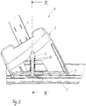
- a carrier system 1 according to Figures 1 to 3 is part of a rear bicycle carrier that is intended for rear attachment to a motor vehicle, in particular to a trailer hitch of a passenger car.
- the rear bicycle carrier has a carrier frame on which at least one carrier rail 2 of the carrier system 1 is attached.
- the carrier rail 2 has at least a length of a wheelbase of a bicycle and is made of a light metal alloy in an extrusion process as a hollow profile.
- a cross section the support rail 2 is based on the 3 recognizable.
- the hollow profile of the carrier rail 2 has a central, upwardly open guide groove, which is designed as a T-profile in cross section and has two profile legs 9 facing one another on opposite sides, which form undercuts for the guide groove—seen in the vertical direction of the carrier rail 2.
- a wheel shell 3 is supported on the carrier rail 2 and has a wheel shell housing made of plastic.
- the wheel shell 3 is mounted to be displaceable along the carrier rail 2 .
- the wheel shell 3 is held on the carrier rail 2 by a clamping piece 7 which is coupled to the wheel shell 3 by means of a carrier unit 6 .
- the clamping piece 7 is guided in a longitudinally displaceable manner in the guide groove of the carrier rail 2 and is positively limited in the vertical direction upwards by the groove legs 9 of the guide groove, which serve as undercuts.
- the clamping piece 7 is in one piece with the carrier unit 6 , which has a carrier column extending in the vertical direction within the wheel housing housing and two carrier extensions 8 protruding on opposite sides in the transverse direction of the carrier rail 2 .
- the carrier unit 6 is mounted in a receiving area 11 within the wheel shell housing so that it can move to a limited extent in the vertical direction.
- a compression spring arrangement 10 which is designed as a helical compression spring coaxially surrounding the support column, permanently loads the support unit 6 upwards in the vertical direction, so that the clamping piece 7 can be locked both in the clamping position described below and in the 3
- the release position shown rests permanently without play on the respective underside of the groove leg 9 of the guide groove of the carrier rail 2.
- a flexible securing band 4 is held on the right carrier extension 8, which is aligned upwards through a corresponding recess in the wheel housing.
- a safety unit 5 is held, which has a manually operable ratchet arrangement.
- the flexible securing band 4 is designed as a locking band.
- a holding section 12 is provided on the securing band 4 which encompasses the carrier extension 8 .
- a further holding section 13 is assigned to the safety unit 5 , which grips around the opposite carrier extension 8 and is thus connected to the carrier unit 6 .
- the wheel shell 3 is in the Figures 1 to 3 Positioning shown along the carrier rail 2 displaceable, wherein the clamping piece 7 slides with its upper side on the underside of the groove legs 9 of the guide groove.
- the bicycle is placed on the carrier rail 2, with a wheel, whether front wheel or rear wheel, being supported by the wheel shell 3 by moving the wheel shell 3 in the direction of this wheel.
- the flexible securing strap 4 is then threaded through the corresponding spokes of the wheel and on the opposite side in the safety unit 5 is pushed in and lashed, whereby the safety strap 4 closes around the rim of the wheel.
- the carrier system 1a according to Figures 4 to 6 largely corresponds to the carrier system 1 described above with regard to its intended use, its structure and its function, so that reference is made to the statements on the carrier system 1 to avoid repetition. Below are the differences in the carrier system 1 according to the Figures 4 to 6 in relation to the carrier system 1 according to Figures 1 to 3 described. Functionally identical parts and sections are provided with the same reference numbers, but with the addition of the letter a.
- the carrier unit 6a is formed by sheet metal angles, which is movably mounted in the vertical direction in receiving sections 11a within the wheel housing housing.
- the carrier unit 6a has, on opposite sides, outwardly and upwardly protruding leg sections which form holding sections 12a and 13a for the securing band 4a on the one hand and the securing unit 5a on the other.
- Retaining bolts 8a serve to connect the corresponding retaining section 12a or 13a and the securing band 4a or the securing unit 5a.
- the metal bracket construction forming the support unit 6a is designed to be dimensionally stable.
- the metal angle construction In the area of its underside, the metal angle construction has two clamping legs which protrude outwards and which form the clamping piece 7a.
- the support unit 6a formed by the metal angle construction is mounted in the receiving sections 11a of the wheel housing of the wheel housing 3a so that it can move in the vertical direction to a limited extent.
- a clamping and release function of the clamping piece 7a in the carrier system 1a corresponds to the function of the carrier system 1.
- the carrier unit 6a is inevitably due to the coupling via the retaining bolts 8a relative to the Wheel shell housing pulled upwards, whereby tops of the clamping legs of the metal angle construction, which form the clamping piece 7a, are pressed from below against the grooved legs 9 of the carrier rail 2. This achieves the desired clamping effect.
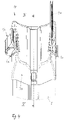
- the carrier system 1b has a wheel shell 3b with a wheel shell housing made of plastic, which is provided with a base 17 .
- a carrier pin 15 is mounted so that it can move linearly in the vertical direction, which is coupled to an eccentric lever 6b and together with this forms an eccentric clamping unit.
- the carrier bolt 15 is connected in the region of its underside to a clamping piece 7b, which is held in a manner not shown in a T-shaped guide groove of a carrier rail, also not shown.
- the eccentric lever 6b can be screwed onto the carrier bolt 15, which is provided with an external thread.
- the eccentric lever 6b has, as shown in the 8 and 9 can be seen, an eccentric contour section, which is supported on the floor 17 and depending on the position of the eccentric lever 6b on the support bolt 15 exerts a tensile force in the vertical direction upwards.
- a securing band 4b and a securing unit 5b are also arranged on the wheel housing, the structure of which corresponds to the securing bands 4 and 4a or securing units 5 and 5a described above.
- the eccentric lever 6b partially protrudes from a slot 16 of a housing section 14 of the wheel housing.
- the slit 16 forms a longitudinal slit formed along a pivot plane of the eccentric lever 6b.
- the pivot plane of the eccentric lever 6b is spanned by the longitudinal direction and vertical direction of the support rail, not shown.
- the housing section 14 can be detachably connected to the wheel housing.
- the housing section 14 serves as a screen in the area of the contact surface of the wheel housing to prevent dirt in the area of the contact surface of the wheel housing from penetrating into the interior of the wheel housing 3b and leading to malfunctions in the eccentric clamping unit.
- the carrier system 1c according to Figures 10 to 12 uses indirectly, ie indirectly, a clamping principle, as in the embodiments according to Figures 1 to 6 is used. Otherwise, the purpose of use of the carrier system 1c as well as that of the carrier system 1b corresponds to Figures 7 to 9 the purpose of the previously based on the Figures 1 to 6 described embodiments. To avoid repetition, reference is therefore made to the previous statements.
- the carrier system 1c has a recess in which a contact body 18 that can be lifted is arranged.
- the contact body 18 extends in the longitudinal direction of the wheel shell 3c over almost the entire length of the contact surface of the wheel shell housing for a corresponding wheel R.
- the contact body 18 is mounted in the recess of the wheel shell housing so that it can lift and is permanently spring-loaded in the vertical direction upwards by several compression springs 19, which are on the housing side are supported in the wheel housing of the wheel housing 3c (see 11 and 12 ).
- the contact body 18 is resiliently movable.
- the contact body 18 is in the region of its underside in contact with a carrier unit 6c, which is designed as a large leaf spring and is pivotably mounted about a pivot bearing 20 fixed to the housing.
- the carrier unit 6c carries a clamping piece 7c, which is designed as a one-piece section of the leaf spring. If a compressive force is exerted obliquely from above by the tire of a bicycle wheel being placed on the contact body 18, the contact body 18 deviates downwards into the recess of the wheel housing, as a result of which the leaf spring forming the carrier unit 6c is carried along downwards.
- the lower end area of the leaf spring which forms the clamping piece 7c, pivots upwards about the pivot axis 20 and rests against the corresponding groove legs of the T-shaped guide groove of the carrier rail 2 in the area of the undercuts 9.
- the clamping effect is maintained by a non-illustrated combination of a safety strap and a ratchet-shaped safety unit.
- the corresponding slot-shaped mounts for mounting a securing strap and an opposite securing unit on the wheel housing are in 10 recognizable.
- Backup tape and backup unit are advantageously designed as based on the 1 is recognizable.
Landscapes
- Engineering & Computer Science (AREA)
- Mechanical Engineering (AREA)
- Fittings On The Vehicle Exterior For Carrying Loads, And Devices For Holding Or Mounting Articles (AREA)
Applications Claiming Priority (1)
| Application Number | Priority Date | Filing Date | Title |
|---|---|---|---|
| DE102021207883.4A DE102021207883B3 (de) | 2021-07-22 | 2021-07-22 | Trägersystem für ein Zweirad |
Publications (1)
| Publication Number | Publication Date |
|---|---|
| EP4122771A1 true EP4122771A1 (fr) | 2023-01-25 |
Family
ID=82308324
Family Applications (1)
| Application Number | Title | Priority Date | Filing Date |
|---|---|---|---|
| EP22180916.3A Pending EP4122771A1 (fr) | 2021-07-22 | 2022-06-24 | Système de support pour un deux-roues |
Country Status (2)
| Country | Link |
|---|---|
| EP (1) | EP4122771A1 (fr) |
| DE (1) | DE102021207883B3 (fr) |
Citations (6)
| Publication number | Priority date | Publication date | Assignee | Title |
|---|---|---|---|---|
| DE3890700C2 (de) * | 1987-09-02 | 1996-12-12 | Js Products Ab | Träger zum Tragen von Fahrrädern oder anderen Lasten |
| US5833074A (en) * | 1995-04-06 | 1998-11-10 | Phillips; Cal M. | Fast-loading, protective bicycle rack |
| US20070164065A1 (en) * | 2005-08-09 | 2007-07-19 | Davis Brian F | Adjustable bicycle wheel retainer |
| DE102010015652B4 (de) | 2010-04-15 | 2017-05-18 | Atera Gmbh | Aufnahmevorrichtung für ein Rad eines Fahrrades |
| US20170349113A1 (en) * | 2016-06-05 | 2017-12-07 | Yakima Products, Inc. | Fork-mount bicycle carrier |
| EP3453540A1 (fr) * | 2017-09-11 | 2019-03-13 | ATERA GmbH | Coque de roue destinée à recevoir une roue d'un deux roues ainsi que dispositif de profilé de support d'une unité de support de deux roues dotée d'un profilé de support et d'une telle coque de roue |
Family Cites Families (3)
| Publication number | Priority date | Publication date | Assignee | Title |
|---|---|---|---|---|
| US469261A (en) | 1892-02-23 | Method of making bolts | ||
| SE9804017D0 (sv) | 1998-11-23 | 1998-11-23 | Mont Blanc Ind Ab | Lastbärarsystem för fordon |
| US7441679B1 (en) | 2003-11-12 | 2008-10-28 | Sportrack Llc | One sided adjustable cross rail |
-
2021
- 2021-07-22 DE DE102021207883.4A patent/DE102021207883B3/de active Active
-
2022
- 2022-06-24 EP EP22180916.3A patent/EP4122771A1/fr active Pending
Patent Citations (6)
| Publication number | Priority date | Publication date | Assignee | Title |
|---|---|---|---|---|
| DE3890700C2 (de) * | 1987-09-02 | 1996-12-12 | Js Products Ab | Träger zum Tragen von Fahrrädern oder anderen Lasten |
| US5833074A (en) * | 1995-04-06 | 1998-11-10 | Phillips; Cal M. | Fast-loading, protective bicycle rack |
| US20070164065A1 (en) * | 2005-08-09 | 2007-07-19 | Davis Brian F | Adjustable bicycle wheel retainer |
| DE102010015652B4 (de) | 2010-04-15 | 2017-05-18 | Atera Gmbh | Aufnahmevorrichtung für ein Rad eines Fahrrades |
| US20170349113A1 (en) * | 2016-06-05 | 2017-12-07 | Yakima Products, Inc. | Fork-mount bicycle carrier |
| EP3453540A1 (fr) * | 2017-09-11 | 2019-03-13 | ATERA GmbH | Coque de roue destinée à recevoir une roue d'un deux roues ainsi que dispositif de profilé de support d'une unité de support de deux roues dotée d'un profilé de support et d'une telle coque de roue |
Also Published As
| Publication number | Publication date |
|---|---|
| DE102021207883B3 (de) | 2022-11-10 |
Similar Documents
| Publication | Publication Date | Title |
|---|---|---|
| DE4342400C2 (de) | Überrollbügeleinrichtung | |
| DE3726711C2 (fr) | ||
| DE4345523C2 (de) | Überrollschutzsystem | |
| EP1884410B1 (fr) | Porte-charge | |
| DE112010002531T5 (de) | Querstangen-klemmvorrichtung | |
| EP0647545A1 (fr) | Barre transversale pour chargement de toit sur une voiture automobile équipée de rails de toit | |
| DE60017190T2 (de) | Fahrzeugmontierter gepäckträger | |
| EP0754595B1 (fr) | Système variable de fixation rapide d?un coffre de toit sur les transverses d'une galerie de toit | |
| WO2013037365A1 (fr) | Porte-charge de toit pour véhicule automobile | |
| DE19803210C2 (de) | Vorrichtung zum Befestigen von Gegenständen im Gepäckraum eines Kraftfahrzeugs | |
| DE10206780B4 (de) | Befestigungsvorrichtung für einen Kindersitz | |
| DE102009016528B4 (de) | Lastenträger für ein Kraftfahrzeug | |
| DE19812490A1 (de) | Einrichtung zur lösbaren Befestigung eines Sitzes, insbesondere Fahrzeugsitzes, an einer längsverlaufenden Schiene | |
| DE19528308C2 (de) | Fahrzeug, insbesondere Personenkraftwagen | |
| DE102021207883B3 (de) | Trägersystem für ein Zweirad | |
| DE10228582A1 (de) | Fahrradträger für ein Kraftfahrzeug | |
| EP2842806B1 (fr) | Dispositif de plancher de compartiment à bagages pour un compartiment à bagages d'un véhicule de tourisme | |
| WO1997008017A1 (fr) | Galerie pour velo | |
| EP0813992A2 (fr) | Siège d'enfant pour véhicules de transport de passagers | |
| DE19922752B4 (de) | Lastenträgersystem für eine Anhängekupplung | |
| EP2765032B1 (fr) | Support de charge avec pièces porte-charge stockées en mouvement sur un support de base | |
| EP2755864A1 (fr) | Support de charge de toit pour véhicules automobiles | |
| EP2607176B1 (fr) | Support de charge avec une pièce porte-charge et un élément d'appui | |
| DE102011010579A1 (de) | Vorrichtung zur Befestigung eines Fahrrades in einem Fahrzeuginnenraum | |
| DE8226078U1 (de) | Halterungsvorrichtung für Fahrräder |
Legal Events
| Date | Code | Title | Description |
|---|---|---|---|
| PUAI | Public reference made under article 153(3) epc to a published international application that has entered the european phase |
Free format text: ORIGINAL CODE: 0009012 |
|
| STAA | Information on the status of an ep patent application or granted ep patent |
Free format text: STATUS: THE APPLICATION HAS BEEN PUBLISHED |
|
| AK | Designated contracting states |
Kind code of ref document: A1 Designated state(s): AL AT BE BG CH CY CZ DE DK EE ES FI FR GB GR HR HU IE IS IT LI LT LU LV MC MK MT NL NO PL PT RO RS SE SI SK SM TR |
|
| P01 | Opt-out of the competence of the unified patent court (upc) registered |
Effective date: 20230519 |
|
| STAA | Information on the status of an ep patent application or granted ep patent |
Free format text: STATUS: REQUEST FOR EXAMINATION WAS MADE |
|
| 17P | Request for examination filed |
Effective date: 20230725 |
|
| RBV | Designated contracting states (corrected) |
Designated state(s): AL AT BE BG CH CY CZ DE DK EE ES FI FR GB GR HR HU IE IS IT LI LT LU LV MC MK MT NL NO PL PT RO RS SE SI SK SM TR |