EP4122771A1 - Carrier system for a bicycle - Google Patents
Carrier system for a bicycle Download PDFInfo
- Publication number
- EP4122771A1 EP4122771A1 EP22180916.3A EP22180916A EP4122771A1 EP 4122771 A1 EP4122771 A1 EP 4122771A1 EP 22180916 A EP22180916 A EP 22180916A EP 4122771 A1 EP4122771 A1 EP 4122771A1
- Authority
- EP
- European Patent Office
- Prior art keywords
- wheel
- carrier
- housing
- unit
- clamping
- Prior art date
- Legal status (The legal status is an assumption and is not a legal conclusion. Google has not performed a legal analysis and makes no representation as to the accuracy of the status listed.)
- Pending
Links
Images


Classifications
-
- B—PERFORMING OPERATIONS; TRANSPORTING
- B60—VEHICLES IN GENERAL
- B60R—VEHICLES, VEHICLE FITTINGS, OR VEHICLE PARTS, NOT OTHERWISE PROVIDED FOR
- B60R9/00—Supplementary fittings on vehicle exterior for carrying loads, e.g. luggage, sports gear or the like
- B60R9/04—Carriers associated with vehicle roof
- B60R9/048—Carriers characterised by article-gripping, -covering,-retaining, or -locking means
-
- B—PERFORMING OPERATIONS; TRANSPORTING
- B60—VEHICLES IN GENERAL
- B60R—VEHICLES, VEHICLE FITTINGS, OR VEHICLE PARTS, NOT OTHERWISE PROVIDED FOR
- B60R9/00—Supplementary fittings on vehicle exterior for carrying loads, e.g. luggage, sports gear or the like
- B60R9/08—Supplementary fittings on vehicle exterior for carrying loads, e.g. luggage, sports gear or the like specially adapted for sports gear
- B60R9/10—Supplementary fittings on vehicle exterior for carrying loads, e.g. luggage, sports gear or the like specially adapted for sports gear for cycles
Definitions
- the invention relates to a carrier system for a bicycle with a carrier rail and with a wheel shell for supporting a wheel of the bicycle, which is slidably guided on the carrier rail and which is assigned a locking device for fixing the position of the wheel shell on the carrier rail.
- Such a carrier system is generally known for vehicle roof carriers or vehicle rear carriers.
- the well-known carrier system has several carrier rails, each of which is provided with two wheel shells in order to be able to support and fix the front wheel and the rear wheel of the corresponding two-wheeler.
- the wheel shells can be moved along the carrier rail and are fixed in a defined position relative to the carrier rail using wing screws.
- a carrier system for a bicycle is known in which a wheel shell is held on a carrier rail which is provided with a flexible locking strap and a ratchet device.
- the locking band and the ratchet device are held on opposite sides of a wheel shell housing of the wheel shell.
- the object of the invention is to create a carrier system of the type mentioned at the outset that enables a two-wheeler to be conveniently and safely assembled and disassembled on the carrier rail.
- the locking device is designed as a manually operated quick-release device.
- the quick-release device can preferably be operated with one hand, so that an operator can hold the two-wheeler with one hand and operate the quick-release device with the other hand.
- the solution according to the invention is suitable for all types of two-wheelers, in particular bicycles, e-bikes, mopeds, scooters, light motorcycles or other single-track motor vehicles such as motorcycles.
- a quick-action clamping device is understood to mean locking devices that can cover a large clamping distance in a short time during a clamping process, such as, in particular, lever kinematics, a ratchet device or the like.
- a prerequisite for the quick-action clamping device is that a locking element can be transferred from a release position into a locking position in a short time.
- the quick-action clamping device is designed as an eccentric clamping unit and has a manually operated eccentric lever, which can be converted into a locking position in the vertical direction downwards and into a release position in the vertical direction upwards.
- the vertical direction is related to a coordinate system assigned to the carrier rail, so that a longitudinal direction corresponds to a longitudinal extension of the carrier rail, a transverse direction to a width extension of the carrier rail and a vertical direction to an extension aligned orthogonally to the transverse extension and the longitudinal extension. Due to the fact that the eccentric lever is transferred into its locking position by a downward movement, an ergonomically favorable operability by an operator is provided. A downward movement allows a higher force to be applied by an operator than a movement in the opposite direction.
- the eccentric lever is preferably aligned in the longitudinal direction and can be moved out of this longitudinal extension for a pivoting movement in the vertical direction.
- the eccentric lever is thus advantageously pivotably mounted in a pivoting plane which is spanned by the vertical direction and the longitudinal direction of the carrier rail.
- the eccentric lever has an eccentric cam disk which, during a pivoting movement of the eccentric lever, exerts an increased torque with increasing pivoting travel, which acts on a clamping piece assigned to the locking device, i.e. the quick-release device, in order to clamp the wheel shell relative to the carrier rail Lifting movement exerts in the vertical direction.
- the eccentric lever is arranged within a housing section of a wheel housing of the wheel housing and protrudes outwards through an opening in the housing section such that the eccentric lever can be gripped manually.
- the eccentric lever is in the longitudinal direction of the wheel housing, i. H. in the direction of longitudinal extent of the carrier rail, aligned in the housing section.
- the opening is preferably designed as a slot, the width of which is slightly wider than the width of the eccentric lever, and the length of which is matched to a maximum pivoting path of the eccentric lever between the release position and the locked position.
- the housing section covers corresponding functional components of the quick-action clamping device and thus keeps them free of dirt and unintentional contact with other objects, so that protection against unintentional loosening can be achieved.
- the housing section is detachably held on the wheel housing. This enables access to the functional components of the eccentric clamping unit in a simple manner.
- the quick-release device with the safety strap and the safety unit is of this type in operative connection that the position of the wheel shell is fixed by the quick-release device synchronously with tensioning of the securing strap in the securing unit.
- the quick-release device has a clamping piece which is arranged in the carrier rail and is pressed in a clamping position against an undercut of the carrier rail, and the clamping piece is held on a carrier unit which is mounted in the wheel shell housing so that it can move in the vertical direction, and the security band and the security unit are directly or indirectly mechanically coupled to the carrier unit.
- the vertical direction is to be seen orthogonally to a longitudinal extension of the carrier rail.
- the carrier unit can be mounted in the wheel shell housing so that it can move linearly, pivotably or move along a curved path.
- the carrier rail is advantageously formed as a hollow profile made from a light metal alloy by extrusion.
- the clamping piece is preferably guided in a profile groove which is open at the top and is undercut in order to enable the clamping piece to bear in a form-fitting manner in the vertical direction.
- the profile groove is open at the top by means of a longitudinal slit, resulting in an approximately T-shaped profile groove when viewed in cross section.
- the clamping piece is either manufactured separately and mechanically held on the carrier unit by suitable fastening means, or the clamping piece is designed in one piece with the carrier unit.
- the direct or indirect mechanical coupling of the security band and the security unit to the carrier unit is to be understood as meaning a mechanical operative connection between the security band and security unit as well as the carrier unit, wherein the operative connection can be provided indirectly via other functional components or directly by connecting the security band and security unit to the carrier unit.
- the carrier unit is mounted in a linear guide of the wheel shell housing so that it can be lifted to a limited extent.
- the carrier unit is in Vertical direction at least largely mounted linearly movable in the wheel housing.
- the carrier unit is designed to be dimensionally stable and is preferably made from at least one metal part.
- the carrier unit is associated with a restoring spring arrangement, which permanently loads the carrier unit relative to the wheel housing in the direction of the clamping position. This ensures a permanent sliding contact of the clamping piece with corresponding undercut legs of the carrier rail, so that tilting is avoided when the wheel shell is manually shifted in the release position of the clamping piece.
- the carrier unit is pivotably mounted relative to the wheel housing, and the carrier unit is coupled to a positive guide arranged on the wheel housing, which initiates a movement of the carrier unit depending on the insertion of the wheel into the wheel housing.
- This configuration represents an indirect mechanical coupling of the security band and the security unit with the carrier unit, i.e. an indirect connection between the corresponding functional components.
- the carrier unit is automatically displaced in such a way that the clamping piece is transferred into its clamping position.
- the positive guide has a resiliently movable contact body which, in the unloaded state, protrudes upwards over a bearing surface of the wheel shell housing for the wheel.
- the contact body When a wheel is inserted into the wheel shell, the contact body is pressed into the contact surface of the wheel shell housing in the manner of a button, whereby due to a mechanical operative connection between the contact body and the carrier unit, the corresponding movement of the contact body is transmitted to the clamping piece in order to move the clamping piece into its clamping position convict.
- a tight lashing of the safety strap fixes this clamping position inevitably.
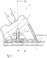
- a carrier system 1 according to Figures 1 to 3 is part of a rear bicycle carrier that is intended for rear attachment to a motor vehicle, in particular to a trailer hitch of a passenger car.
- the rear bicycle carrier has a carrier frame on which at least one carrier rail 2 of the carrier system 1 is attached.
- the carrier rail 2 has at least a length of a wheelbase of a bicycle and is made of a light metal alloy in an extrusion process as a hollow profile.
- a cross section the support rail 2 is based on the 3 recognizable.
- the hollow profile of the carrier rail 2 has a central, upwardly open guide groove, which is designed as a T-profile in cross section and has two profile legs 9 facing one another on opposite sides, which form undercuts for the guide groove—seen in the vertical direction of the carrier rail 2.
- a wheel shell 3 is supported on the carrier rail 2 and has a wheel shell housing made of plastic.
- the wheel shell 3 is mounted to be displaceable along the carrier rail 2 .
- the wheel shell 3 is held on the carrier rail 2 by a clamping piece 7 which is coupled to the wheel shell 3 by means of a carrier unit 6 .
- the clamping piece 7 is guided in a longitudinally displaceable manner in the guide groove of the carrier rail 2 and is positively limited in the vertical direction upwards by the groove legs 9 of the guide groove, which serve as undercuts.
- the clamping piece 7 is in one piece with the carrier unit 6 , which has a carrier column extending in the vertical direction within the wheel housing housing and two carrier extensions 8 protruding on opposite sides in the transverse direction of the carrier rail 2 .
- the carrier unit 6 is mounted in a receiving area 11 within the wheel shell housing so that it can move to a limited extent in the vertical direction.
- a compression spring arrangement 10 which is designed as a helical compression spring coaxially surrounding the support column, permanently loads the support unit 6 upwards in the vertical direction, so that the clamping piece 7 can be locked both in the clamping position described below and in the 3
- the release position shown rests permanently without play on the respective underside of the groove leg 9 of the guide groove of the carrier rail 2.
- a flexible securing band 4 is held on the right carrier extension 8, which is aligned upwards through a corresponding recess in the wheel housing.
- a safety unit 5 is held, which has a manually operable ratchet arrangement.
- the flexible securing band 4 is designed as a locking band.
- a holding section 12 is provided on the securing band 4 which encompasses the carrier extension 8 .
- a further holding section 13 is assigned to the safety unit 5 , which grips around the opposite carrier extension 8 and is thus connected to the carrier unit 6 .
- the wheel shell 3 is in the Figures 1 to 3 Positioning shown along the carrier rail 2 displaceable, wherein the clamping piece 7 slides with its upper side on the underside of the groove legs 9 of the guide groove.
- the bicycle is placed on the carrier rail 2, with a wheel, whether front wheel or rear wheel, being supported by the wheel shell 3 by moving the wheel shell 3 in the direction of this wheel.
- the flexible securing strap 4 is then threaded through the corresponding spokes of the wheel and on the opposite side in the safety unit 5 is pushed in and lashed, whereby the safety strap 4 closes around the rim of the wheel.
- the carrier system 1a according to Figures 4 to 6 largely corresponds to the carrier system 1 described above with regard to its intended use, its structure and its function, so that reference is made to the statements on the carrier system 1 to avoid repetition. Below are the differences in the carrier system 1 according to the Figures 4 to 6 in relation to the carrier system 1 according to Figures 1 to 3 described. Functionally identical parts and sections are provided with the same reference numbers, but with the addition of the letter a.
- the carrier unit 6a is formed by sheet metal angles, which is movably mounted in the vertical direction in receiving sections 11a within the wheel housing housing.
- the carrier unit 6a has, on opposite sides, outwardly and upwardly protruding leg sections which form holding sections 12a and 13a for the securing band 4a on the one hand and the securing unit 5a on the other.
- Retaining bolts 8a serve to connect the corresponding retaining section 12a or 13a and the securing band 4a or the securing unit 5a.
- the metal bracket construction forming the support unit 6a is designed to be dimensionally stable.
- the metal angle construction In the area of its underside, the metal angle construction has two clamping legs which protrude outwards and which form the clamping piece 7a.
- the support unit 6a formed by the metal angle construction is mounted in the receiving sections 11a of the wheel housing of the wheel housing 3a so that it can move in the vertical direction to a limited extent.
- a clamping and release function of the clamping piece 7a in the carrier system 1a corresponds to the function of the carrier system 1.
- the carrier unit 6a is inevitably due to the coupling via the retaining bolts 8a relative to the Wheel shell housing pulled upwards, whereby tops of the clamping legs of the metal angle construction, which form the clamping piece 7a, are pressed from below against the grooved legs 9 of the carrier rail 2. This achieves the desired clamping effect.
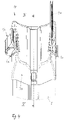
- the carrier system 1b has a wheel shell 3b with a wheel shell housing made of plastic, which is provided with a base 17 .
- a carrier pin 15 is mounted so that it can move linearly in the vertical direction, which is coupled to an eccentric lever 6b and together with this forms an eccentric clamping unit.
- the carrier bolt 15 is connected in the region of its underside to a clamping piece 7b, which is held in a manner not shown in a T-shaped guide groove of a carrier rail, also not shown.
- the eccentric lever 6b can be screwed onto the carrier bolt 15, which is provided with an external thread.
- the eccentric lever 6b has, as shown in the 8 and 9 can be seen, an eccentric contour section, which is supported on the floor 17 and depending on the position of the eccentric lever 6b on the support bolt 15 exerts a tensile force in the vertical direction upwards.
- a securing band 4b and a securing unit 5b are also arranged on the wheel housing, the structure of which corresponds to the securing bands 4 and 4a or securing units 5 and 5a described above.
- the eccentric lever 6b partially protrudes from a slot 16 of a housing section 14 of the wheel housing.
- the slit 16 forms a longitudinal slit formed along a pivot plane of the eccentric lever 6b.
- the pivot plane of the eccentric lever 6b is spanned by the longitudinal direction and vertical direction of the support rail, not shown.
- the housing section 14 can be detachably connected to the wheel housing.
- the housing section 14 serves as a screen in the area of the contact surface of the wheel housing to prevent dirt in the area of the contact surface of the wheel housing from penetrating into the interior of the wheel housing 3b and leading to malfunctions in the eccentric clamping unit.
- the carrier system 1c according to Figures 10 to 12 uses indirectly, ie indirectly, a clamping principle, as in the embodiments according to Figures 1 to 6 is used. Otherwise, the purpose of use of the carrier system 1c as well as that of the carrier system 1b corresponds to Figures 7 to 9 the purpose of the previously based on the Figures 1 to 6 described embodiments. To avoid repetition, reference is therefore made to the previous statements.
- the carrier system 1c has a recess in which a contact body 18 that can be lifted is arranged.
- the contact body 18 extends in the longitudinal direction of the wheel shell 3c over almost the entire length of the contact surface of the wheel shell housing for a corresponding wheel R.
- the contact body 18 is mounted in the recess of the wheel shell housing so that it can lift and is permanently spring-loaded in the vertical direction upwards by several compression springs 19, which are on the housing side are supported in the wheel housing of the wheel housing 3c (see 11 and 12 ).
- the contact body 18 is resiliently movable.
- the contact body 18 is in the region of its underside in contact with a carrier unit 6c, which is designed as a large leaf spring and is pivotably mounted about a pivot bearing 20 fixed to the housing.
- the carrier unit 6c carries a clamping piece 7c, which is designed as a one-piece section of the leaf spring. If a compressive force is exerted obliquely from above by the tire of a bicycle wheel being placed on the contact body 18, the contact body 18 deviates downwards into the recess of the wheel housing, as a result of which the leaf spring forming the carrier unit 6c is carried along downwards.
- the lower end area of the leaf spring which forms the clamping piece 7c, pivots upwards about the pivot axis 20 and rests against the corresponding groove legs of the T-shaped guide groove of the carrier rail 2 in the area of the undercuts 9.
- the clamping effect is maintained by a non-illustrated combination of a safety strap and a ratchet-shaped safety unit.
- the corresponding slot-shaped mounts for mounting a securing strap and an opposite securing unit on the wheel housing are in 10 recognizable.
- Backup tape and backup unit are advantageously designed as based on the 1 is recognizable.
Abstract
Ein Trägersystem mit einer Trägerschiene sowie mit einer Radschale zur Stützung eines Rads des Zweirads, die auf der Trägerschiene verschiebbar geführt ist, und der eine Arretiereinrichtung zur Positionsfixierung der Radschale an der Trägerschiene zugeordnet ist, ist bekannt.Erfindungsgemäß ist die Arretiereinrichtung als manuell bedienbare Schnellspanneinrichtung ausgebildet.Einsatz für Fahrradheckträger an PersonenkraftwagenA carrier system with a carrier rail and with a wheel shell for supporting a wheel of the two-wheeler, which is slidably guided on the carrier rail and which is assigned a locking device for fixing the position of the wheel shell on the carrier rail is known. According to the invention, the locking device is designed as a manually operated quick-release device .Use for rear bicycle racks on passenger cars
Description
Die Erfindung betrifft ein Trägersystem für ein Zweirad mit einer Trägerschiene sowie mit einer Radschale zur Stützung eines Rads des Zweirads, die auf der Trägerschiene verschiebbar geführt ist, und der eine Arretiereinrichtung zur Positionsfixierung der Radschale an der Trägerschiene zugeordnet ist.The invention relates to a carrier system for a bicycle with a carrier rail and with a wheel shell for supporting a wheel of the bicycle, which is slidably guided on the carrier rail and which is assigned a locking device for fixing the position of the wheel shell on the carrier rail.
Ein derartiges Trägersystem ist für Fahrzeugdachträger oder Fahrzeugheckträger allgemein bekannt. Das bekannte Trägersystem weist mehrere Trägerschienen auf, die jeweils mit zwei Radschalen versehen sind, um das Vorderrad und das Hinterrad des entsprechenden Zweirads stützen und fixieren zu können. Die Radschalen sind entlang der Trägerschiene verschiebbar geführt und werden mithilfe von Flügelschrauben in einer definierten Position relativ zur Trägerschiene fixiert.Such a carrier system is generally known for vehicle roof carriers or vehicle rear carriers. The well-known carrier system has several carrier rails, each of which is provided with two wheel shells in order to be able to support and fix the front wheel and the rear wheel of the corresponding two-wheeler. The wheel shells can be moved along the carrier rail and are fixed in a defined position relative to the carrier rail using wing screws.
Aus der
Aufgabe der Erfindung ist es, ein Trägersystem der eingangs genannten Art zu schaffen, das eine komfortable und sichere Montage und Demontage eines Zweirads auf der Trägerschiene ermöglicht.The object of the invention is to create a carrier system of the type mentioned at the outset that enables a two-wheeler to be conveniently and safely assembled and disassembled on the carrier rail.
Diese Aufgabe wird dadurch gelöst, dass die Arretiereinrichtung als manuell bedienbare Schnellspanneinrichtung ausgebildet ist. Vorzugsweise ist die Schnellspanneinrichtung einhändig bedienbar, so dass eine Bedienperson mit einer Hand das Zweirad halten kann und mit der anderen Hand die Schnellspanneinrichtung bedienen kann. Die erfindungsgemäße Lösung eignet sich für alle Arten von Zweirädern, insbesondere für Fahrräder, für E-Bikes, für Mofas, für Roller, für Leichtkrafträder oder für andere einspurige Kraftfahrzeuge wie Motorräder. Unter einer Schnellspanneinrichtung werden Arretiereinrichtungen verstanden, die bei einem Spannvorgang einen großen Spannweg in kurzer Zeit zurücklegen können, wie insbesondere eine Hebelkinematik, eine Ratscheneinrichtung oder Ähnliches. Voraussetzung für die Schnellspanneinrichtung ist es, dass in kurzer Zeit eine Überführung eines Arretierelements aus einer Freigabestellung in eine Arretierstellung vorgesehen ist.This object is achieved in that the locking device is designed as a manually operated quick-release device. The quick-release device can preferably be operated with one hand, so that an operator can hold the two-wheeler with one hand and operate the quick-release device with the other hand. The solution according to the invention is suitable for all types of two-wheelers, in particular bicycles, e-bikes, mopeds, scooters, light motorcycles or other single-track motor vehicles such as motorcycles. A quick-action clamping device is understood to mean locking devices that can cover a large clamping distance in a short time during a clamping process, such as, in particular, lever kinematics, a ratchet device or the like. A prerequisite for the quick-action clamping device is that a locking element can be transferred from a release position into a locking position in a short time.
In Ausgestaltung der Erfindung ist die Schnellspanneinrichtung als Exzenterspanneinheit gestaltet und weist einen manuell bedienbaren Exzenterhebel auf, der in Hochrichtung nach unten in eine Sperrstellung und in Hochrichtung nach oben in eine Freigabestellung überführbar ist. Die Hochrichtung ist bezogen auf ein der Trägerschiene zugeordnetes Koordinatensystem, so dass eine Längsrichtung einer Längserstreckung der Trägerschiene, eine Querrichtung einer Breitenerstreckung der Trägerschiene und eine Hochrichtung einer orthogonal zu der Quererstreckung und der Längserstreckung ausgerichteten Erstreckung entsprechen. Dadurch, dass der Exzenterhebel durch eine Bewegung nach unten in seine Arretierstellung überführt wird, ist eine ergonomisch günstige Bedienbarkeit durch eine Bedienperson gegeben. Eine Bewegung nach unten ermöglicht durch eine Bedienperson eine höhere Kraftaufbringung als eine Bewegung in entgegengesetzter Richtung. Der Exzenterhebel ist vorzugsweise in Längsrichtung ausgerichtet und für eine Schwenkbewegung in Hochrichtung aus dieser Längserstreckung heraus beweglich. Damit ist der Exzenterhebel vorteilhaft in einer Schwenkebene schwenkbeweglich gelagert, die durch die Hochrichtung und die Längsrichtung der Trägerschiene aufgespannt ist. Der Exzenterhebel weist eine exzentrische Kurvenscheibe auf, die bei einer Schwenkbewegung des Exzenterhebels mit zunehmendem Schwenkweg ein erhöhtes Drehmoment ausübt, das auf ein Klemmstück, das der Arretiereinrichtung, d.h. der Schnellspanneinrichtung, zugeordnet ist, wirkt, um die Radschale relativ zur Trägerschiene zu verklemmen, eine Hubbewegung in Hochrichtung ausübt.In an embodiment of the invention, the quick-action clamping device is designed as an eccentric clamping unit and has a manually operated eccentric lever, which can be converted into a locking position in the vertical direction downwards and into a release position in the vertical direction upwards. The vertical direction is related to a coordinate system assigned to the carrier rail, so that a longitudinal direction corresponds to a longitudinal extension of the carrier rail, a transverse direction to a width extension of the carrier rail and a vertical direction to an extension aligned orthogonally to the transverse extension and the longitudinal extension. Due to the fact that the eccentric lever is transferred into its locking position by a downward movement, an ergonomically favorable operability by an operator is provided. A downward movement allows a higher force to be applied by an operator than a movement in the opposite direction. The eccentric lever is preferably aligned in the longitudinal direction and can be moved out of this longitudinal extension for a pivoting movement in the vertical direction. The eccentric lever is thus advantageously pivotably mounted in a pivoting plane which is spanned by the vertical direction and the longitudinal direction of the carrier rail. The eccentric lever has an eccentric cam disk which, during a pivoting movement of the eccentric lever, exerts an increased torque with increasing pivoting travel, which acts on a clamping piece assigned to the locking device, i.e. the quick-release device, in order to clamp the wheel shell relative to the carrier rail Lifting movement exerts in the vertical direction.
In weiterer Ausgestaltung der Erfindung ist der Exzenterhebel innerhalb eines Gehäuseabschnitts eines Radschalengehäuses der Radschale angeordnet und ragt durch eine Öffnung des Gehäuseabschnitts derart über den Gehäuseabschnitt nach außen ab, dass der Exzenterhebel manuell ergreifbar ist. Der Exzenterhebel ist in der Längsrichtung des Radschalengehäuses, d. h. in Längserstreckungsrichtung der Trägerschiene, in dem Gehäuseabschnitt ausgerichtet. Vorzugsweise ist die Öffnung als Schlitz gestaltet, dessen Breite geringfügig breiter ist als eine Breite des Exzenterhebels, und dessen Länge auf einen maximalen Schwenkweg des Exzenterhebels zwischen der Freigabestellung und der Sperrstellung abgestimmt ist. Der Gehäuseabschnitt überdeckt entsprechende Funktionskomponenten der Schnellspanneinrichtung und hält diese damit verschmutzungsfrei und frei von unbeabsichtigten Kontakten mit anderen Gegenständen, so dass ein Schutz gegen ein unbeabsichtigtes Lösen erzielbar ist.In a further embodiment of the invention, the eccentric lever is arranged within a housing section of a wheel housing of the wheel housing and protrudes outwards through an opening in the housing section such that the eccentric lever can be gripped manually. The eccentric lever is in the longitudinal direction of the wheel housing, i. H. in the direction of longitudinal extent of the carrier rail, aligned in the housing section. The opening is preferably designed as a slot, the width of which is slightly wider than the width of the eccentric lever, and the length of which is matched to a maximum pivoting path of the eccentric lever between the release position and the locked position. The housing section covers corresponding functional components of the quick-action clamping device and thus keeps them free of dirt and unintentional contact with other objects, so that protection against unintentional loosening can be achieved.
In weiterer Ausgestaltung der Erfindung ist der Gehäuseabschnitt lösbar an dem Radschalengehäuse gehalten. Dadurch ist in einfacher Weise eine Zugänglichkeit zu Funktionskomponenten der Exzenterspanneinheit ermöglicht.In a further embodiment of the invention, the housing section is detachably held on the wheel housing. This enables access to the functional components of the eccentric clamping unit in a simple manner.
In weiterer Ausgestaltung der Erfindung mit einem dem Radschalengehäuse zugeordneten Sicherungsband für ein Rad des Zweirads und einer das Sicherungsband in einer Sicherungsstellung aufnehmenden und spannenden Sicherungseinheit, die an einer dem Sicherungsband gegenüberliegenden Seite eines Radschalengehäuses vorgesehen ist, ist die Schnellspanneinrichtung mit dem Sicherungsband und der Sicherungseinheit derart in Wirkverbindung, dass eine Positionsfixierung der Radschale durch die Schnellspanneinrichtung synchron zu einem Spannen des Sicherungsbands in der Sicherungseinheit erfolgt. Dadurch übernehmen das Sicherungsband und die Sicherungseinheit eine Doppelfunktion, da neben der Festzurrung des Rads an der Radschale gleichzeitig auch die Arretierung der Radschale relativ zur Trägerschiene erfolgt.In a further embodiment of the invention with a safety strap assigned to the wheel housing for one wheel of the two-wheeler and a safety unit that receives and tensions the safety strap in a safety position and is provided on a side of a wheel housing opposite the safety strap, the quick-release device with the safety strap and the safety unit is of this type in operative connection that the position of the wheel shell is fixed by the quick-release device synchronously with tensioning of the securing strap in the securing unit. As a result, the safety strap and the safety unit take on a dual function, since in addition to lashing the wheel to the wheel shell, the wheel shell is also locked relative to the carrier rail at the same time.
In weiterer Ausgestaltung der Erfindung weist die Schnellspanneinrichtung ein Klemmstück auf, das in der Trägerschiene angeordnet ist und in einer Klemmstellung gegen einen Hinterschnitt der Trägerschiene gepresst ist, und das Klemmstück ist an einer Trägereinheit gehalten, die in Hochrichtung beweglich in dem Radschalengehäuse gelagert ist, und das Sicherungsband und die Sicherungseinheit sind direkt oder indirekt mechanisch mit der Trägereinheit gekoppelt. Die Hochrichtung ist - wie zuvor bereits ausgeführt wurde - orthogonal zu einer Längserstreckung der Trägerschiene zu sehen. Die Trägereinheit kann linearbeweglich, schwenkbeweglich oder längs einer Kurvenbahn beweglich in dem Radschalengehäuse gelagert sein. Maßgeblich ist, dass auf das Klemmstück eine Bewegung in Hochrichtung übertragen wird, um je nach Bewegungsrichtung eine Klemmstellung oder eine Freigabestellung des Klemmstücks zu erzielen. Die Trägerschiene ist vorteilhaft als durch Strangpressen hergestelltes Hohlprofil aus einer Leichtmetalllegierung gebildet. Das Klemmstück ist vorzugsweise in einer nach oben offenen Profilnut geführt, die hinterschnitten ist, um eine formschlüssige Anlage des Klemmstücks in Hochrichtung nach oben ermöglichen zu können. Die Profilnut ist mittels eines Längsschlitzes nach oben offen, so dass sich im Querschnitt gesehen eine etwa T-förmige Profilnut ergibt. Das Klemmstück ist entweder separat hergestellt und an der Trägereinheit durch geeignete Befestigungsmittel mechanisch gehalten oder das Klemmstück ist einteilig mit der Trägereinheit gestaltet. Unter der direkten oder indirekten mechanischen Kopplung des Sicherungsbands und der Sicherungseinheit mit der Trägereinheit ist eine mechanische Wirkverbindung zwischen Sicherungsband und Sicherungseinheit sowie Trägereinheit zu verstehen, wobei die Wirkverbindung mittelbar über weitere Funktionskomponenten oder unmittelbar durch Verbindung von Sicherungsband und Sicherungseinheit mit der Trägereinheit vorgesehen sein kann.In a further embodiment of the invention, the quick-release device has a clamping piece which is arranged in the carrier rail and is pressed in a clamping position against an undercut of the carrier rail, and the clamping piece is held on a carrier unit which is mounted in the wheel shell housing so that it can move in the vertical direction, and the security band and the security unit are directly or indirectly mechanically coupled to the carrier unit. As already explained above, the vertical direction is to be seen orthogonally to a longitudinal extension of the carrier rail. The carrier unit can be mounted in the wheel shell housing so that it can move linearly, pivotably or move along a curved path. What is decisive is that a movement in the vertical direction is transmitted to the clamping piece in order to achieve a clamping position or a release position of the clamping piece, depending on the direction of movement. The carrier rail is advantageously formed as a hollow profile made from a light metal alloy by extrusion. The clamping piece is preferably guided in a profile groove which is open at the top and is undercut in order to enable the clamping piece to bear in a form-fitting manner in the vertical direction. The profile groove is open at the top by means of a longitudinal slit, resulting in an approximately T-shaped profile groove when viewed in cross section. The clamping piece is either manufactured separately and mechanically held on the carrier unit by suitable fastening means, or the clamping piece is designed in one piece with the carrier unit. The direct or indirect mechanical coupling of the security band and the security unit to the carrier unit is to be understood as meaning a mechanical operative connection between the security band and security unit as well as the carrier unit, wherein the operative connection can be provided indirectly via other functional components or directly by connecting the security band and security unit to the carrier unit.
In weiterer Ausgestaltung der Erfindung ist die Trägereinheit in einer Linearführung des Radschalengehäuses begrenzt hubbeweglich gelagert. Dadurch ist die Trägereinheit in Hochrichtung zumindest weitgehend linearbeweglich in dem Radschalengehäuse gelagert. Die Trägereinheit ist formsteif gestaltet und vorzugsweise aus wenigstens einem Metallteil hergestellt. In vorteilhafter Weise ist der Trägereinheit eine Rückstellfederanordnung zugeordnet, die die Trägereinheit relativ zum Radschalengehäuse permanent in Richtung der Klemmstellung belastet. Dadurch ist eine permanente gleitende Anlage des Klemmstücks an entsprechenden Hinterschnittschenkeln der Trägerschiene gewährleistet, so dass ein Verkanten bei einem manuellen Verschieben der Radschale in der Freigabestellung des Klemmstücks vermieden wird.In a further embodiment of the invention, the carrier unit is mounted in a linear guide of the wheel shell housing so that it can be lifted to a limited extent. As a result, the carrier unit is in Vertical direction at least largely mounted linearly movable in the wheel housing. The carrier unit is designed to be dimensionally stable and is preferably made from at least one metal part. Advantageously, the carrier unit is associated with a restoring spring arrangement, which permanently loads the carrier unit relative to the wheel housing in the direction of the clamping position. This ensures a permanent sliding contact of the clamping piece with corresponding undercut legs of the carrier rail, so that tilting is avoided when the wheel shell is manually shifted in the release position of the clamping piece.
In weiterer Ausgestaltung der Erfindung ist die Trägereinheit schwenkbeweglich relativ zu dem Radschalengehäuse gelagert, und die Trägereinheit ist mit einer an dem Radschalengehäuse angeordneten Zwangsführung gekoppelt, die eine Bewegung der Trägereinheit initiiert abhängig von einem Einsetzen des Rads in das Radschalengehäuse. Diese Ausgestaltung stellt eine indirekte mechanische Kopplung des Sicherungsbands und der Sicherungseinheit mit der Trägereinheit dar, d.h. eine mittelbare Verbindung zwischen den entsprechenden Funktionskomponenten. Durch ein entsprechendes Aufsetzen und Festzurren des Rads an der Radschale mittels des Sicherungsbands und der Sicherungseinheit wird zwangsläufig die Trägereinheit derart verlagert, dass das Klemmstück in seine Klemmstellung überführt wird.In a further embodiment of the invention, the carrier unit is pivotably mounted relative to the wheel housing, and the carrier unit is coupled to a positive guide arranged on the wheel housing, which initiates a movement of the carrier unit depending on the insertion of the wheel into the wheel housing. This configuration represents an indirect mechanical coupling of the security band and the security unit with the carrier unit, i.e. an indirect connection between the corresponding functional components. Appropriately placing and lashing the wheel on the wheel shell by means of the safety strap and the safety unit, the carrier unit is automatically displaced in such a way that the clamping piece is transferred into its clamping position.
In weiterer Ausgestaltung der Erfindung weist die Zwangsführung einen federelastisch beweglichen Kontaktkörper auf, der in unbelastetem Zustand über eine Auflagefläche des Radschalengehäuses für das Rad nach oben abragt. Der Kontaktkörper wird beim Einsetzen eines Rads in die Radschale nach Art eines Tasters in die Auflagefläche des Radschalengehäuses hineingedrückt, wodurch aufgrund einer mechanischen Wirkverbindung zwischen dem Kontaktkörper und der Trägereinheit die entsprechende Bewegung des Kontaktkörpers auf das Klemmstück übertragen wird, um das Klemmstück in seine Klemmstellung zu überführen. Ein Festzurren des Sicherungsbands fixiert diese Klemmstellung zwangsläufig.In a further embodiment of the invention, the positive guide has a resiliently movable contact body which, in the unloaded state, protrudes upwards over a bearing surface of the wheel shell housing for the wheel. When a wheel is inserted into the wheel shell, the contact body is pressed into the contact surface of the wheel shell housing in the manner of a button, whereby due to a mechanical operative connection between the contact body and the carrier unit, the corresponding movement of the contact body is transmitted to the clamping piece in order to move the clamping piece into its clamping position convict. A tight lashing of the safety strap fixes this clamping position inevitably.
Weitere Vorteile und Merkmale der Erfindung ergeben sich aus den Ansprüchen sowie aus der nachfolgenden Beschreibung bevorzugter Ausführungsbeispiele der Erfindung, die anhand der Zeichnungen dargestellt sind.
- Fig. 1
- zeigt in einer Draufsicht eine erste Ausführungsform eines erfindungsgemäßen Trägersystems im Bereich einer Radschale,
- Fig. 2
- einen Längsschnitt entlang der Schnittlinie II-II durch das Trägersystem nach
Fig. 1 , - Fig. 3
- einen Querschnitt durch das Trägersystem nach
Fig. 2 entlang der Schnittlinie III-III inFig. 2 , - Fig. 4
- in einer Draufsicht eine weitere Ausführungsform eines erfindungsgemäßen Trägersystems im Bereich einer Radschale,
- Fig. 5
- einen Längsschnitt entlang der Schnittlinie V-V durch das Trägersystem nach
Fig. 4 , - Fig. 6
- in vergrößerter Darstellung einen Querschnitt entlang der Schnittlinie VI-VI durch das Trägersystem gemäß
Fig. 5 , - Fig. 7
- in perspektivischer Darstellung eine Radschale für eine weitere Ausführungsform eines erfindungsgemäßen Trägersystems,
- Fig. 8
- in einem Längsschnitt die Radschale nach
Fig. 7 , - Fig. 9
- eine perspektivische Explosionsdarstellung der Radschale nach den
Fig. 7 ,und 8 - Fig. 10
- in perspektivischer Darstellung eine weitere Radschale einer weiteren Ausführungsform eines erfindungsgemäßen Trägersystems,
- Fig. 11
- einen Längsschnitt durch die Radschale gemäß
Fig. 10 und - Fig. 12
- in schematischer Darstellung das Funktionsprinzip des mit einer Radschale gemäß den
Fig. 10 und 11 versehenen, erfindungsgemäßen Trägersystems gemäß einer letzten Ausführungsform der Erfindung.
- 1
- shows a top view of a first embodiment of a carrier system according to the invention in the area of a wheel shell,
- 2
- a longitudinal section along the section line II-II through the
carrier system 1 , - 3
- a cross-section through the
carrier system 2 along section line III-III in2 , - 4
- in a plan view a further embodiment of a carrier system according to the invention in the area of a wheel shell,
- figure 5
- a longitudinal section along the section line VV through the
carrier system 4 , - 6
- in an enlarged representation a cross section along the section line VI-VI through the carrier system according to FIG
figure 5 , - 7
- a perspective view of a wheel shell for a further embodiment of a carrier system according to the invention,
- 8
- the wheel housing in a
longitudinal section 7 , - 9
- a perspective exploded view of the wheel shell according to
Figures 7 and 8 , - 10
- a perspective view of another wheel shell of another embodiment of a carrier system according to the invention,
- 11
- according to a longitudinal section through the
wheel shell 10 and - 12
- in a schematic representation of the principle of operation with a wheel according to
Figures 10 and 11 provided, inventive carrier system according to a final embodiment of the invention.
Ein Trägersystem 1 nach den
Die Radschale 3 ist in der in den
Das Trägersystem 1a nach den
Bei dem Trägersystem 1a nach den
Eine Klemm- und Freigabefunktion des Klemmstücks 7a bei dem Trägersystem 1a nach den
Bei der Ausführungsform nach den
Anhand der
Das Trägersystem 1c nach den
Im Bereich einer Auflagefläche des Radschalengehäuses der Radschale 3c weist das Trägersystem 1c eine Aussparung auf, in der ein hubbeweglicher Kontaktkörper 18 angeordnet ist. Der Kontaktkörper 18 erstreckt sich in Längsrichtung der Radschale 3c über nahezu eine gesamte Länge der Auflagefläche des Radschalengehäuses für ein entsprechendes Rad R. Der Kontaktkörper 18 ist in der Aussparung des Radschalengehäuses hubbeweglich gelagert und permanent in Hochrichtung nach oben federbelastet durch mehrere Druckfedern 19, die gehäuseseitig im Radschalengehäuse der Radschale 3c abgestützt sind (siehe
Claims (10)
Applications Claiming Priority (1)
| Application Number | Priority Date | Filing Date | Title |
|---|---|---|---|
| DE102021207883.4A DE102021207883B3 (en) | 2021-07-22 | 2021-07-22 | Carrier system for a two-wheeler |
Publications (1)
| Publication Number | Publication Date |
|---|---|
| EP4122771A1 true EP4122771A1 (en) | 2023-01-25 |
Family
ID=82308324
Family Applications (1)
| Application Number | Title | Priority Date | Filing Date |
|---|---|---|---|
| EP22180916.3A Pending EP4122771A1 (en) | 2021-07-22 | 2022-06-24 | Carrier system for a bicycle |
Country Status (2)
| Country | Link |
|---|---|
| EP (1) | EP4122771A1 (en) |
| DE (1) | DE102021207883B3 (en) |
Citations (6)
| Publication number | Priority date | Publication date | Assignee | Title |
|---|---|---|---|---|
| DE3890700C2 (en) * | 1987-09-02 | 1996-12-12 | Js Products Ab | Car roof carrier for bicycles |
| US5833074A (en) * | 1995-04-06 | 1998-11-10 | Phillips; Cal M. | Fast-loading, protective bicycle rack |
| US20070164065A1 (en) * | 2005-08-09 | 2007-07-19 | Davis Brian F | Adjustable bicycle wheel retainer |
| DE102010015652B4 (en) | 2010-04-15 | 2017-05-18 | Atera Gmbh | Cradle for a wheel of a bicycle |
| US20170349113A1 (en) * | 2016-06-05 | 2017-12-07 | Yakima Products, Inc. | Fork-mount bicycle carrier |
| EP3453540A1 (en) * | 2017-09-11 | 2019-03-13 | ATERA GmbH | Wheel shell for receiving of a wheel of a two-wheeled vehicle and a support profile arrangement bicycle carrier unit with a support profile and high intensity wheel shell |
Family Cites Families (3)
| Publication number | Priority date | Publication date | Assignee | Title |
|---|---|---|---|---|
| US469261A (en) | 1892-02-23 | Method of making bolts | ||
| SE9804017D0 (en) | 1998-11-23 | 1998-11-23 | Mont Blanc Ind Ab | Cargo carrier system for vehicles |
| US7441679B1 (en) | 2003-11-12 | 2008-10-28 | Sportrack Llc | One sided adjustable cross rail |
-
2021
- 2021-07-22 DE DE102021207883.4A patent/DE102021207883B3/en active Active
-
2022
- 2022-06-24 EP EP22180916.3A patent/EP4122771A1/en active Pending
Patent Citations (6)
| Publication number | Priority date | Publication date | Assignee | Title |
|---|---|---|---|---|
| DE3890700C2 (en) * | 1987-09-02 | 1996-12-12 | Js Products Ab | Car roof carrier for bicycles |
| US5833074A (en) * | 1995-04-06 | 1998-11-10 | Phillips; Cal M. | Fast-loading, protective bicycle rack |
| US20070164065A1 (en) * | 2005-08-09 | 2007-07-19 | Davis Brian F | Adjustable bicycle wheel retainer |
| DE102010015652B4 (en) | 2010-04-15 | 2017-05-18 | Atera Gmbh | Cradle for a wheel of a bicycle |
| US20170349113A1 (en) * | 2016-06-05 | 2017-12-07 | Yakima Products, Inc. | Fork-mount bicycle carrier |
| EP3453540A1 (en) * | 2017-09-11 | 2019-03-13 | ATERA GmbH | Wheel shell for receiving of a wheel of a two-wheeled vehicle and a support profile arrangement bicycle carrier unit with a support profile and high intensity wheel shell |
Also Published As
| Publication number | Publication date |
|---|---|
| DE102021207883B3 (en) | 2022-11-10 |
Similar Documents
| Publication | Publication Date | Title |
|---|---|---|
| DE4342400C2 (en) | Rollover bar device | |
| DE3726711C2 (en) | ||
| DE4345523C2 (en) | Vehicle roll-over bar with inner and outer guides | |
| EP1884410B1 (en) | Rear load carrier | |
| DE112010002531T5 (en) | CROSS BAR TERMINAL DEVICE | |
| EP0647545A1 (en) | Cross-bar for roof loads on a motor car provided with roof rails | |
| DE60017190T2 (en) | VEHICLE ASSEMBLED LUGGAGE RACK | |
| DE19526477C1 (en) | Holder for detachable fastening of roof storage boxes on motor vehicles | |
| WO2013037365A1 (en) | Roof load carrier for motor vehicles | |
| DE19803210C2 (en) | Device for fastening objects in the luggage compartment of a motor vehicle | |
| DE10206780B4 (en) | Fastening device for a child seat | |
| DE19812490A1 (en) | Device for detachable attachment of motor vehicle seat on longitudinally extending rail | |
| DE19528308C2 (en) | Vehicle, in particular passenger cars | |
| DE102021207883B3 (en) | Carrier system for a two-wheeler | |
| DE10228582A1 (en) | Bicycle rack for a motor vehicle | |
| EP2842806B1 (en) | Luggage compartment base device for a luggage compartment of a passenger car | |
| DE1949085C3 (en) | Vehicle seat, in particular vehicle seat | |
| WO1997008017A1 (en) | Roof-mounted cycle-rack | |
| EP0813992A2 (en) | Infant seat for passenger transport vehicles | |
| DE19922752B4 (en) | Load carrier system for a trailer hitch | |
| EP2765032B1 (en) | Load support with mobile load bearing parts mounted on a base support | |
| EP2755864A1 (en) | Roof load carrier for motor vehicles | |
| EP2607176B1 (en) | Load support with a load bearing part and a supporting element | |
| DE102011010579A1 (en) | Device for fixing bicycle in interior of e.g. combination-passenger car, has bearing part mounted in region of recess in backrest, and coupling element mounted in quick release fastener for connecting fastener and bearing part | |
| DE8226078U1 (en) | Bracket for bicycles |
Legal Events
| Date | Code | Title | Description |
|---|---|---|---|
| PUAI | Public reference made under article 153(3) epc to a published international application that has entered the european phase |
Free format text: ORIGINAL CODE: 0009012 |
|
| STAA | Information on the status of an ep patent application or granted ep patent |
Free format text: STATUS: THE APPLICATION HAS BEEN PUBLISHED |
|
| AK | Designated contracting states |
Kind code of ref document: A1 Designated state(s): AL AT BE BG CH CY CZ DE DK EE ES FI FR GB GR HR HU IE IS IT LI LT LU LV MC MK MT NL NO PL PT RO RS SE SI SK SM TR |
|
| P01 | Opt-out of the competence of the unified patent court (upc) registered |
Effective date: 20230519 |
|
| STAA | Information on the status of an ep patent application or granted ep patent |
Free format text: STATUS: REQUEST FOR EXAMINATION WAS MADE |
|
| 17P | Request for examination filed |
Effective date: 20230725 |
|
| RBV | Designated contracting states (corrected) |
Designated state(s): AL AT BE BG CH CY CZ DE DK EE ES FI FR GB GR HR HU IE IS IT LI LT LU LV MC MK MT NL NO PL PT RO RS SE SI SK SM TR |