EP4119320B1 - Verfahren und vorrichtung zum aufbereiten, bearbeiten und/oder recyceln von kunststoffmaterialien - Google Patents
Verfahren und vorrichtung zum aufbereiten, bearbeiten und/oder recyceln von kunststoffmaterialien Download PDFInfo
- Publication number
- EP4119320B1 EP4119320B1 EP22192112.5A EP22192112A EP4119320B1 EP 4119320 B1 EP4119320 B1 EP 4119320B1 EP 22192112 A EP22192112 A EP 22192112A EP 4119320 B1 EP4119320 B1 EP 4119320B1
- Authority
- EP
- European Patent Office
- Prior art keywords
- receiving container
- mixing
- control unit
- electromagnetic radiation
- spectra
- Prior art date
- Legal status (The legal status is an assumption and is not a legal conclusion. Google has not performed a legal analysis and makes no representation as to the accuracy of the status listed.)
- Active
Links
Images


Classifications
-
- B—PERFORMING OPERATIONS; TRANSPORTING
- B09—DISPOSAL OF SOLID WASTE; RECLAMATION OF CONTAMINATED SOIL
- B09B—DISPOSAL OF SOLID WASTE NOT OTHERWISE PROVIDED FOR
- B09B3/00—Destroying solid waste or transforming solid waste into something useful or harmless
-
- B—PERFORMING OPERATIONS; TRANSPORTING
- B29—WORKING OF PLASTICS; WORKING OF SUBSTANCES IN A PLASTIC STATE IN GENERAL
- B29B—PREPARATION OR PRETREATMENT OF THE MATERIAL TO BE SHAPED; MAKING GRANULES OR PREFORMS; RECOVERY OF PLASTICS OR OTHER CONSTITUENTS OF WASTE MATERIAL CONTAINING PLASTICS
- B29B17/00—Recovery of plastics or other constituents of waste material containing plastics
- B29B17/0026—Recovery of plastics or other constituents of waste material containing plastics by agglomeration or compacting
- B29B17/0036—Recovery of plastics or other constituents of waste material containing plastics by agglomeration or compacting of large particles, e.g. beads, granules, pellets, flakes, slices
-
- B—PERFORMING OPERATIONS; TRANSPORTING
- B29—WORKING OF PLASTICS; WORKING OF SUBSTANCES IN A PLASTIC STATE IN GENERAL
- B29B—PREPARATION OR PRETREATMENT OF THE MATERIAL TO BE SHAPED; MAKING GRANULES OR PREFORMS; RECOVERY OF PLASTICS OR OTHER CONSTITUENTS OF WASTE MATERIAL CONTAINING PLASTICS
- B29B17/00—Recovery of plastics or other constituents of waste material containing plastics
- B29B17/04—Disintegrating plastics, e.g. by milling
- B29B17/0412—Disintegrating plastics, e.g. by milling to large particles, e.g. beads, granules, flakes, slices
-
- C—CHEMISTRY; METALLURGY
- C08—ORGANIC MACROMOLECULAR COMPOUNDS; THEIR PREPARATION OR CHEMICAL WORKING-UP; COMPOSITIONS BASED THEREON
- C08J—WORKING-UP; GENERAL PROCESSES OF COMPOUNDING; AFTER-TREATMENT NOT COVERED BY SUBCLASSES C08B, C08C, C08F, C08G or C08H
- C08J11/00—Recovery or working-up of waste materials
- C08J11/04—Recovery or working-up of waste materials of polymers
-
- G—PHYSICS
- G01—MEASURING; TESTING
- G01N—INVESTIGATING OR ANALYSING MATERIALS BY DETERMINING THEIR CHEMICAL OR PHYSICAL PROPERTIES
- G01N21/00—Investigating or analysing materials by the use of optical means, i.e. using sub-millimetre waves, infrared, visible or ultraviolet light
- G01N21/17—Systems in which incident light is modified in accordance with the properties of the material investigated
- G01N21/25—Colour; Spectral properties, i.e. comparison of effect of material on the light at two or more different wavelengths or wavelength bands
- G01N21/255—Details, e.g. use of specially adapted sources, lighting or optical systems
-
- G—PHYSICS
- G01—MEASURING; TESTING
- G01N—INVESTIGATING OR ANALYSING MATERIALS BY DETERMINING THEIR CHEMICAL OR PHYSICAL PROPERTIES
- G01N21/00—Investigating or analysing materials by the use of optical means, i.e. using sub-millimetre waves, infrared, visible or ultraviolet light
- G01N21/17—Systems in which incident light is modified in accordance with the properties of the material investigated
- G01N21/25—Colour; Spectral properties, i.e. comparison of effect of material on the light at two or more different wavelengths or wavelength bands
- G01N21/31—Investigating relative effect of material at wavelengths characteristic of specific elements or molecules, e.g. atomic absorption spectrometry
-
- G—PHYSICS
- G01—MEASURING; TESTING
- G01N—INVESTIGATING OR ANALYSING MATERIALS BY DETERMINING THEIR CHEMICAL OR PHYSICAL PROPERTIES
- G01N21/00—Investigating or analysing materials by the use of optical means, i.e. using sub-millimetre waves, infrared, visible or ultraviolet light
- G01N21/17—Systems in which incident light is modified in accordance with the properties of the material investigated
- G01N21/47—Scattering, i.e. diffuse reflection
- G01N21/49—Scattering, i.e. diffuse reflection within a body or fluid
- G01N21/51—Scattering, i.e. diffuse reflection within a body or fluid inside a container, e.g. in an ampoule
-
- G—PHYSICS
- G01—MEASURING; TESTING
- G01N—INVESTIGATING OR ANALYSING MATERIALS BY DETERMINING THEIR CHEMICAL OR PHYSICAL PROPERTIES
- G01N21/00—Investigating or analysing materials by the use of optical means, i.e. using sub-millimetre waves, infrared, visible or ultraviolet light
- G01N21/62—Systems in which the material investigated is excited whereby it emits light or causes a change in wavelength of the incident light
- G01N21/63—Systems in which the material investigated is excited whereby it emits light or causes a change in wavelength of the incident light optically excited
- G01N21/64—Fluorescence; Phosphorescence
- G01N21/645—Specially adapted constructive features of fluorimeters
-
- G—PHYSICS
- G01—MEASURING; TESTING
- G01N—INVESTIGATING OR ANALYSING MATERIALS BY DETERMINING THEIR CHEMICAL OR PHYSICAL PROPERTIES
- G01N21/00—Investigating or analysing materials by the use of optical means, i.e. using sub-millimetre waves, infrared, visible or ultraviolet light
- G01N21/62—Systems in which the material investigated is excited whereby it emits light or causes a change in wavelength of the incident light
- G01N21/63—Systems in which the material investigated is excited whereby it emits light or causes a change in wavelength of the incident light optically excited
- G01N21/65—Raman scattering
-
- G—PHYSICS
- G01—MEASURING; TESTING
- G01N—INVESTIGATING OR ANALYSING MATERIALS BY DETERMINING THEIR CHEMICAL OR PHYSICAL PROPERTIES
- G01N21/00—Investigating or analysing materials by the use of optical means, i.e. using sub-millimetre waves, infrared, visible or ultraviolet light
- G01N21/84—Systems specially adapted for particular applications
- G01N21/85—Investigating moving fluids or granular solids
-
- G—PHYSICS
- G01—MEASURING; TESTING
- G01N—INVESTIGATING OR ANALYSING MATERIALS BY DETERMINING THEIR CHEMICAL OR PHYSICAL PROPERTIES
- G01N33/00—Investigating or analysing materials by specific methods not covered by groups G01N1/00 - G01N31/00
- G01N33/44—Resins; Plastics; Rubber; Leather
- G01N33/442—Resins; Plastics
-
- B—PERFORMING OPERATIONS; TRANSPORTING
- B29—WORKING OF PLASTICS; WORKING OF SUBSTANCES IN A PLASTIC STATE IN GENERAL
- B29B—PREPARATION OR PRETREATMENT OF THE MATERIAL TO BE SHAPED; MAKING GRANULES OR PREFORMS; RECOVERY OF PLASTICS OR OTHER CONSTITUENTS OF WASTE MATERIAL CONTAINING PLASTICS
- B29B17/00—Recovery of plastics or other constituents of waste material containing plastics
- B29B17/02—Separating plastics from other materials
- B29B2017/0213—Specific separating techniques
- B29B2017/0255—Specific separating techniques using different melting or softening temperatures of the materials to be separated
- B29B2017/0258—Specific separating techniques using different melting or softening temperatures of the materials to be separated using heated surfaces for selective softening or melting of at least one plastic ingredient
-
- B—PERFORMING OPERATIONS; TRANSPORTING
- B29—WORKING OF PLASTICS; WORKING OF SUBSTANCES IN A PLASTIC STATE IN GENERAL
- B29B—PREPARATION OR PRETREATMENT OF THE MATERIAL TO BE SHAPED; MAKING GRANULES OR PREFORMS; RECOVERY OF PLASTICS OR OTHER CONSTITUENTS OF WASTE MATERIAL CONTAINING PLASTICS
- B29B17/00—Recovery of plastics or other constituents of waste material containing plastics
- B29B17/02—Separating plastics from other materials
- B29B2017/0213—Specific separating techniques
- B29B2017/0279—Optical identification, e.g. cameras or spectroscopy
-
- B—PERFORMING OPERATIONS; TRANSPORTING
- B29—WORKING OF PLASTICS; WORKING OF SUBSTANCES IN A PLASTIC STATE IN GENERAL
- B29B—PREPARATION OR PRETREATMENT OF THE MATERIAL TO BE SHAPED; MAKING GRANULES OR PREFORMS; RECOVERY OF PLASTICS OR OTHER CONSTITUENTS OF WASTE MATERIAL CONTAINING PLASTICS
- B29B17/00—Recovery of plastics or other constituents of waste material containing plastics
- B29B17/04—Disintegrating plastics, e.g. by milling
- B29B2017/0424—Specific disintegrating techniques; devices therefor
- B29B2017/0468—Crushing, i.e. disintegrating into small particles
-
- B—PERFORMING OPERATIONS; TRANSPORTING
- B29—WORKING OF PLASTICS; WORKING OF SUBSTANCES IN A PLASTIC STATE IN GENERAL
- B29B—PREPARATION OR PRETREATMENT OF THE MATERIAL TO BE SHAPED; MAKING GRANULES OR PREFORMS; RECOVERY OF PLASTICS OR OTHER CONSTITUENTS OF WASTE MATERIAL CONTAINING PLASTICS
- B29B17/00—Recovery of plastics or other constituents of waste material containing plastics
- B29B17/04—Disintegrating plastics, e.g. by milling
- B29B2017/0424—Specific disintegrating techniques; devices therefor
- B29B2017/048—Cutter-compactors, e.g. of the EREMA type
-
- B—PERFORMING OPERATIONS; TRANSPORTING
- B29—WORKING OF PLASTICS; WORKING OF SUBSTANCES IN A PLASTIC STATE IN GENERAL
- B29K—INDEXING SCHEME ASSOCIATED WITH SUBCLASSES B29B, B29C OR B29D, RELATING TO MOULDING MATERIALS OR TO MATERIALS FOR MOULDS, REINFORCEMENTS, FILLERS OR PREFORMED PARTS, e.g. INSERTS
- B29K2101/00—Use of unspecified macromolecular compounds as moulding material
- B29K2101/12—Thermoplastic materials
-
- G—PHYSICS
- G01—MEASURING; TESTING
- G01N—INVESTIGATING OR ANALYSING MATERIALS BY DETERMINING THEIR CHEMICAL OR PHYSICAL PROPERTIES
- G01N21/00—Investigating or analysing materials by the use of optical means, i.e. using sub-millimetre waves, infrared, visible or ultraviolet light
- G01N21/84—Systems specially adapted for particular applications
- G01N2021/8411—Application to online plant, process monitoring
-
- G—PHYSICS
- G01—MEASURING; TESTING
- G01N—INVESTIGATING OR ANALYSING MATERIALS BY DETERMINING THEIR CHEMICAL OR PHYSICAL PROPERTIES
- G01N21/00—Investigating or analysing materials by the use of optical means, i.e. using sub-millimetre waves, infrared, visible or ultraviolet light
- G01N21/17—Systems in which incident light is modified in accordance with the properties of the material investigated
- G01N21/25—Colour; Spectral properties, i.e. comparison of effect of material on the light at two or more different wavelengths or wavelength bands
- G01N21/31—Investigating relative effect of material at wavelengths characteristic of specific elements or molecules, e.g. atomic absorption spectrometry
- G01N21/3103—Atomic absorption analysis
-
- G—PHYSICS
- G01—MEASURING; TESTING
- G01N—INVESTIGATING OR ANALYSING MATERIALS BY DETERMINING THEIR CHEMICAL OR PHYSICAL PROPERTIES
- G01N21/00—Investigating or analysing materials by the use of optical means, i.e. using sub-millimetre waves, infrared, visible or ultraviolet light
- G01N21/17—Systems in which incident light is modified in accordance with the properties of the material investigated
- G01N21/25—Colour; Spectral properties, i.e. comparison of effect of material on the light at two or more different wavelengths or wavelength bands
- G01N21/31—Investigating relative effect of material at wavelengths characteristic of specific elements or molecules, e.g. atomic absorption spectrometry
- G01N21/33—Investigating relative effect of material at wavelengths characteristic of specific elements or molecules, e.g. atomic absorption spectrometry using ultraviolet light
-
- G—PHYSICS
- G01—MEASURING; TESTING
- G01N—INVESTIGATING OR ANALYSING MATERIALS BY DETERMINING THEIR CHEMICAL OR PHYSICAL PROPERTIES
- G01N21/00—Investigating or analysing materials by the use of optical means, i.e. using sub-millimetre waves, infrared, visible or ultraviolet light
- G01N21/17—Systems in which incident light is modified in accordance with the properties of the material investigated
- G01N21/25—Colour; Spectral properties, i.e. comparison of effect of material on the light at two or more different wavelengths or wavelength bands
- G01N21/31—Investigating relative effect of material at wavelengths characteristic of specific elements or molecules, e.g. atomic absorption spectrometry
- G01N21/35—Investigating relative effect of material at wavelengths characteristic of specific elements or molecules, e.g. atomic absorption spectrometry using infrared light
- G01N21/359—Investigating relative effect of material at wavelengths characteristic of specific elements or molecules, e.g. atomic absorption spectrometry using infrared light using near infrared light
-
- Y—GENERAL TAGGING OF NEW TECHNOLOGICAL DEVELOPMENTS; GENERAL TAGGING OF CROSS-SECTIONAL TECHNOLOGIES SPANNING OVER SEVERAL SECTIONS OF THE IPC; TECHNICAL SUBJECTS COVERED BY FORMER USPC CROSS-REFERENCE ART COLLECTIONS [XRACs] AND DIGESTS
- Y02—TECHNOLOGIES OR APPLICATIONS FOR MITIGATION OR ADAPTATION AGAINST CLIMATE CHANGE
- Y02W—CLIMATE CHANGE MITIGATION TECHNOLOGIES RELATED TO WASTEWATER TREATMENT OR WASTE MANAGEMENT
- Y02W30/00—Technologies for solid waste management
- Y02W30/20—Waste processing or separation
-
- Y—GENERAL TAGGING OF NEW TECHNOLOGICAL DEVELOPMENTS; GENERAL TAGGING OF CROSS-SECTIONAL TECHNOLOGIES SPANNING OVER SEVERAL SECTIONS OF THE IPC; TECHNICAL SUBJECTS COVERED BY FORMER USPC CROSS-REFERENCE ART COLLECTIONS [XRACs] AND DIGESTS
- Y02—TECHNOLOGIES OR APPLICATIONS FOR MITIGATION OR ADAPTATION AGAINST CLIMATE CHANGE
- Y02W—CLIMATE CHANGE MITIGATION TECHNOLOGIES RELATED TO WASTEWATER TREATMENT OR WASTE MANAGEMENT
- Y02W30/00—Technologies for solid waste management
- Y02W30/50—Reuse, recycling or recovery technologies
- Y02W30/52—Mechanical processing of waste for the recovery of materials, e.g. crushing, shredding, separation or disassembly
-
- Y—GENERAL TAGGING OF NEW TECHNOLOGICAL DEVELOPMENTS; GENERAL TAGGING OF CROSS-SECTIONAL TECHNOLOGIES SPANNING OVER SEVERAL SECTIONS OF THE IPC; TECHNICAL SUBJECTS COVERED BY FORMER USPC CROSS-REFERENCE ART COLLECTIONS [XRACs] AND DIGESTS
- Y02—TECHNOLOGIES OR APPLICATIONS FOR MITIGATION OR ADAPTATION AGAINST CLIMATE CHANGE
- Y02W—CLIMATE CHANGE MITIGATION TECHNOLOGIES RELATED TO WASTEWATER TREATMENT OR WASTE MANAGEMENT
- Y02W30/00—Technologies for solid waste management
- Y02W30/50—Reuse, recycling or recovery technologies
- Y02W30/62—Plastics recycling; Rubber recycling
Definitions
- the invention relates to a method for preparing, processing or recycling materials, namely plastic material according to claim 1.
- the invention further relates to a device for carrying out a method according to the invention according to claim 7.
- EP 1 264 170 A2 discloses a multi-head probe system for the spectroscopic analysis of a moving fluid material and provides a spectral analysis system with a probe that can be inserted into a rapidly moving stream or through a window to analyze a material stream moving in a container by irradiation with ultraviolet, visible or infrared light.
- This system can in principle be used in any granular solid, liquid or gas moving through or along a closed or open channel, such as manure, soil, sludge, mining materials, chemicals, pharmaceuticals, food, waste materials, hazardous waste, petroleum and petroleum products, industrial gases, exhaust gases, etc.
- the publication EP 3 128 303 A2 discloses the monitoring of manufacturing processes of pharmaceutical products, food, distillates and other chemical compounds using a spectrometer.
- plastics recycling in particular, one of the main tasks is to process plastics that come from different sources and may have different compositions, which may also be unknown.
- the area of plastics recycling includes, for example, both the area of internal production waste and the area of used plastic products, such as packaging, computer casings, or parts from the automotive sector, etc., so that the starting materials, for example, have greatly varying filler and polymer contents.
- the aim of the processing is to achieve defined quality characteristics for the reuse of the material, such as defined mechanical, optical and/or other properties.
- defined quality characteristics such as defined mechanical, optical and/or other properties.
- an analysis of the incoming and processed materials is necessary in addition to the necessary mechanical requirements.
- the object of the present invention is to provide a method and a device for processing, processing and/or recycling materials such as thermoplastics, with which materials can be processed in a simple and effective manner with the simultaneous possibility of monitoring and controlling the processing process in order to achieve the desired quality characteristics in the process end product.
- This design of a method according to the invention makes it possible to examine the material moving in the receiving container inline spectroscopically and/or spectrometrically and in this way to obtain information about the material, such as additive or filler content and polymer composition, so that the processing process can be controlled according to the information, for example by adding fillers or polymers. In this way, the desired quality characteristics or properties of the end product can be precisely adjusted.
- inline means that the analysis or measurement of the material in the receiving container is integrated into the preparation or processing process line and takes place directly in the line during the preparation and processing of the material.
- the invention relates to a plastic material that is moved and mixed in a cutter-compactor.
- the direction of movement is not important.
- the particles in the receiving container can move in the direction of flow through the receiving container and in the radial direction of the rotating mixing and/or crushing tools.
- a particularly precise examination of the material located in the receiving container can be achieved if at least parts of the lumpy or particulate material located inside the receiving container and rotating there are excited by a physical effect, in particular by electromagnetic radiation, and the measurement signals generated as a reaction to the effect, in particular characteristic spectra of the electromagnetic radiation scattered on the material being measured, are detected, preferably spectrometrically.
- the spectroscopic and/or spectrometric measurement is carried out using atomic spectroscopy or molecular spectroscopy This can be, for example, Raman spectroscopy, NIR spectroscopy, UV/VIS spectroscopy, fluorescence spectroscopy and/or absorption spectroscopy.
- light in the infrared, visible and/or UV light range is used for excitation.
- light with a wavelength in the range of 100 to 1400 nm, preferably 500 to 1000 nm can be used.
- excitation by means of a laser in particular with a wavelength range of 100 nm to 1400 nm and/or with a power in the range of 15 mW to 5 W, preferably 100 to 500 mW, is possible.
- a particularly simple and targeted control of physical properties or quality characteristics in the end product of the process can be achieved, since the detected light is analyzed in order to record specific quantitative and/or qualitative parameters of the plastic material, or changes in these parameters during the process, inline.
- This information or parameters can advantageously be used to monitor and/or control the process and/or to control the process control in the receiving container. This means that an immediate reaction to changes in the parameters during the preparation of the material, for example by adding fillers, is possible, so that the properties of the end product of the process can be controlled in a targeted manner.
- the electromagnetic radiation stimulating the material is focused on a focal point which is located inside the receiving container on or immediately behind the container wall, preferably at a distance of maximum 10 cm behind the container wall.
- the physical effect in particular the electromagnetic radiation, creates a cross-sectional area of the measurement spot from 0.1 mm to 5 mm, in particular from 1 mm to 3 mm, and a penetration depth into the material of 0.3 ⁇ m to 30 ⁇ m, in particular from 8 ⁇ m to 15 ⁇ m, defined volume range is stimulated.
- a particularly frequent and regular exchange of the material at the measuring position or at the focal point can be achieved if the lumpy or particulate material in the outer region of the receiving container, in particular on the side wall of the receiving container, has a direction of movement in the circumferential direction and/or a predominantly upward direction of movement.
- a further improvement in the exchange of material at the measuring position or at the focal point can be ensured by circulating the lumpy or particulate material radially at a speed of 0.3 m/s to 45 m/s and/or in the vertical direction at a speed of 0.1 m/s to 60 m/s. In this way, it can be achieved that the lumpy or particulate material in the outer area of the receiving container, in particular on the side wall of the receiving container, is exchanged frequently and regularly.
- a particularly precise way of deriving information about the material located inside the receiving container can be provided if the lumpy or particulate material located inside the receiving container and rotating there, in particular individual particles of the material, is excited at a large number of predetermined times by a physical effect, in particular electromagnetic radiation, and the mean value of the information about the material measured in each case, in particular about the individual particles, is determined and made available.
- This can preferably be the mean value of the quantitative and/or qualitative parameters of the respective material or the respective particles, which were determined on the basis of selected, preferably all, measured values determined at these times. This results in an average value from the measured values of the individual particles measured.
- Another particularly precise possibility for obtaining information about the material inside the receiving container in which a physical effect emitted by an excitation source with particularly low power is also sufficient, can be provided if the lumpy or particulate material inside the receiving container and rotating there is continuously excited by a physical effect, in particular electromagnetic radiation, for a predetermined period of time, in particular several seconds.
- a physical effect in particular electromagnetic radiation
- common information about the material being measured in particular a quantitative and/or qualitative parameter, is calculated and made available on the basis of the measured values continuously determined within this period. This results in a cumulative measured value for all particles that have moved past the measuring position or the focal point during the measuring period.
- the temperature inside the receiving container and/or the temperature of the material can be measured and the temperature information can be included in the evaluation.
- the measured temperature information can serve as an indication for correcting the information about the material being measured, in particular the quantitative and/or qualitative parameters of the respective material.
- the material temperature can be recorded and used as a specification for correcting the spectra.
- reference information in particular quantitative and/or qualitative reference parameters, preferably reference spectra
- the information determined for the respective material measured, in particular the parameters, preferably the spectra are compared with the reference information, in particular the reference parameters, preferably the reference spectra.
- the deviation from the reference information, in particular the reference parameters, preferably the reference spectra can thus be determined particularly easily and in particular displayed and/or used to monitor and/or control the process control in the receiving container and/or the subsequent process chain.
- the object of the invention is also to provide a device for carrying out a method according to the invention for preparing, processing and/or recycling plastic materials.
- the invention solves this problem with a device having the features according to claim 7.
- the device comprises at least one receiving container, namely a cutting compactor, with a mixing and/or comminution device for the material and with a spectroscopic and/or spectrometric measuring device for analyzing the lumpy or particulate material moving inside the receiving container or for obtaining information about the plastic material being measured in each case, in particular quantitative and/or qualitative parameters of the respective material.
- This design of a device according to the invention makes it possible to carry out a spectroscopic and/or spectrometric measurement or analysis of the plastic material moving in the receiving container inline.
- information about the material such as additive or filler content and polymer composition, can be determined inline, so that the processing process can be controlled according to the information in order to precisely adjust the desired quality characteristics or properties in the end product, for example by adding fillers or polymers.
- a particularly compact embodiment of a device according to the invention which enables inline measurement and analysis of the material to be processed, is provided in that it comprises at least one receiving container, namely a cutting compactor, with a mixing and/or comminution device for the material, at least one spectroscopic and/or spectrometric measuring device for inline measurement of parts of the lumpy or particulate material moving inside the receiving container, and a processing and control unit in data communication with the measuring device.
- the measuring device is designed to emit a physical effect, in particular electromagnetic radiation, to excite the rotating lumpy or particulate material and to detect the measuring signals generated as a reaction to the effect, in particular characteristic spectra of the electromagnetic radiation scattered on the material being measured, preferably spectrometrically.
- the processing and control unit is designed to control the measuring device, to emit the physical effect, in particular electromagnetic radiation, and to detect the resulting measurement signals and to keep the measured values determined in this way available and, if necessary, on the basis of the measured values determined, to derive and keep available information about the material being measured in each case, in particular quantitative and/or qualitative parameters of the respective material.
- a machine specially designed for the processing, processing or recycling of materials A suitable receptacle is provided according to the invention in that the receptacle has a side wall and is substantially conical or cylindrical or has a conical or cylindrical wall section, and optionally also has a lower bottom surface.
- a particularly efficient processing of a wide variety of materials is ensured according to the invention in that at least one rotating mixing and/or comminution tool, in particular rotatable about a vertical axis of rotation, is arranged in the receiving container as a mixing and/or comminution device for moving and mixing, and optionally also for heating, comminution and/or softening, the lumpy or particulate material to be treated, wherein a vortex and/or a mixing vortex can be formed in the receiving container during operation.
- the material forms a vortex and largely only circulates in one plane, while the material flows along the longitudinal axis of the receiving container at a speed of 2 m/h with a peripheral speed of, for example, approximately 0.3 m/s.
- a mixing vortex can be formed.
- a particularly effective processing of the materials in the receiving container can be achieved if the peripheral speed of the mixing and/or crushing tool is selected such that the lumpy or particulate material rotates radially at a speed of 0.3 to 45 m/s and/or in the vertical direction at a speed of 0.1 to 60 m/s. This also advantageously ensures that the material is constantly exchanged at the measuring position or the focal point.
- a particularly simple removal of processed materials from the receiving container is ensured according to the invention in that an opening is formed in the receiving container, in particular in a side wall of the receiving container, through which the pretreated plastic material can be removed from the interior of the receiving container and in that at least one conveyor, in particular an extruder, with at least one screw rotating in a housing, in particular plasticizing or agglomerating, is arranged to receive the pretreated material emerging from the opening.
- the opening in the receiving container can be at the height of the lowest mixing element closest to the ground. and/or crushing tool and the housing can have an intake opening on its front side or in its casing wall for the material to be taken up by the screw, which is connected to the opening.
- the measuring device comprises at least one excitation source acting or directed into the interior of the receiving container for emitting a physical effect, in particular electromagnetic radiation, on at least parts of the lumpy or particulate material located inside the receiving container and rotating there during operation, and at least one detector, in particular a spectroscope, for detecting the measurement signals generated in response to the effect, in particular characteristic spectra of the electromagnetic radiation scattered on the material being measured.
- the excitation source can act, for example, from the direction of the container wall of the receiving container or from the mixing and/or crushing tool or from the bottom surface of the receiving container into the interior of the receiving container.
- a particularly reliable characterization of the material particles located in the receiving container is achieved according to the invention in that the processing and control unit is designed for the spectrometric and/or spectroscopic analysis of the measurement signals generated in response to the impact, in particular of characteristic spectra of the electromagnetic radiation scattered on the material being measured.
- a particularly simple possibility of avoiding disturbing influences emanating from the receiving container on the excitation source and/or the detector of the measuring device of a device according to the invention can be provided if the excitation source and/or the detector and/or the processing and control unit are physically spaced from the receiving container or are coupled to the receiving container in a vibration-free manner, in particular via fiber optic systems and/or light guides.
- the measuring device comprises a device, in particular a detector, for atomic spectroscopy or molecular spectroscopy, in particular for Raman spectroscopy, NIR spectroscopy, UV/VIS spectroscopy, fluorescence spectroscopy and/or absorption spectroscopy.
- the excitation source is designed to emit light in the infrared, visible and/or UV light range, in particular in the range from 100 to 1400 nm, preferably from 500 to 1050 nm.
- a particularly versatile excitation source can be provided if the excitation source is a laser, in particular with a wavelength range of 100 nm to 1400 nm and/or a power in the range of 15 mW to 5 W, preferably from 100 mW to 500 mW.
- a particularly reliable measurement of the materials inside the receiving container with simultaneous physical separation of the receiving container from the measuring device, so that the measuring device remains largely unaffected by disruptive influences emanating from the receiving container, can be provided if at least one measuring opening is provided in the receiving container, in particular in the side wall of the receiving container.
- the measuring opening is designed in such a way that the physical effect emitted by the excitation source, in particular the emitted electromagnetic radiation, acts on the material in the receiving container and scattered light from the receiving container can be detected outside the receiving container.
- a measuring opening which requires particularly minor design changes to the receiving vessel which could cause a static weakening of the receiving vessel can be provided if the measuring opening has a diameter of 0.5 to 100 mm.
- the measuring opening is closed by a window made of material that is permeable, in particular to electromagnetic radiation, such as sapphire glass.
- the window can also be provided with a thickness of 1 to 100 mm.
- the surfaces of the window are flat and aligned parallel to one another.
- this effect can be achieved if the inner surface of the window facing the receiving container is concavely adapted to the radius of the receiving container and the outer surface of the window facing away from the receiving container is designed to be concave parallel to the inner surface.
- the volume range that can be excited by the physical effect, in particular the electromagnetic radiation is defined by a measuring spot cross-sectional area of 0.1 mm to 5 mm, in particular from 1 mm to 3 mm, and a penetration depth into the material of 0.3 ⁇ m to 30 ⁇ m, in particular from 8 ⁇ m to 15 ⁇ m.
- a particularly favorable signal-to-noise ratio of the measurement signals can be achieved if a lens or a lens system is provided for focusing the electromagnetic radiation of the excitation source onto a focal point, wherein the focal point is formed in particular on or immediately behind the window, preferably at a distance of maximum 10 cm behind the window.
- a particularly targeted control of the processing or recycling process of the plastic materials is achieved according to the invention in that the processing and control unit interacts with a process control unit and is in data communication.
- a process control unit is advantageously designed to use data transmitted by the processing and control unit, in particular information about the material being measured in each case, preferably quantitative and/or qualitative parameters of the respective material, to monitor and/or control the process control in the receiving container and/or the subsequent process chain.
- a particularly simple consideration of temperature influences that can influence the measurement signals emitted by the material to be measured can be provided if at least one temperature measuring device is provided upstream of the processing and control unit.
- a temperature measuring device is designed to measure the temperature inside the receiving container and/or the temperature of the material and to transmit it to the processing and control unit.
- the processing and control unit is advantageously designed to use the measured values determined by the at least one temperature measuring device to correct the temperature influence on the information determined for the respective material being measured, in particular the temperature-dependent characteristic spectra of the electromagnetic radiation scattered by the material being measured, and to keep the information corrected in this way, in particular spectra, available.
- a particularly precise correction of temperature influences can be achieved if the temperature measuring device in the receiving container is arranged at the same height, in particular at the same position, as the at least one measuring opening.
- a particularly simple evaluation or analysis of the information determined by the processing and control unit, such as spectra can be provided if the processing and control unit comprises a memory, wherein reference information, in particular quantitative and/or qualitative reference parameters, preferably reference spectra, are stored in the memory and if the processing and control unit is designed to compare the information determined for the respective measured material, in particular the parameters, preferably the spectra, with the reference information, in particular the reference parameters, preferably the reference spectra, and to determine the deviation from the reference information, in particular the reference parameters, preferably the reference spectra, and in particular to forward it to the process control unit and/or a display unit.
- reference information in particular quantitative and/or qualitative reference parameters, preferably reference spectra
- the processing and control unit is designed to compare the information determined for the respective measured material, in particular the parameters, preferably the spectra, with the reference information, in particular the reference parameters, preferably the reference spectra, and to determine the deviation from the reference information, in particular the reference parameters, preferably the reference spectra,
- a measuring device is understood to be a device for recording or displaying and quantitatively and/or qualitatively analyzing a spectrum, which comprises an excitation source and a detector.
- the excitation source and the detector are coordinated with one another.
- Such a measuring device can be a spectrometer.
- a detector is understood to be a device for detecting and breaking down radiation or other physical measured values into a spectrum, which can be integrated into a measuring device.
- a detector can be a spectroscope.
- thermoplastic or partially thermoplastic materials are carried out by the cutter-compactor when operating a cutter-compactor-extruder combination, i.e. an assembly of a cutter-compactor, a so-called "preconditioning unit" PCU, with an extruder.
- a cutter-compactor or such a preconditioning unit PCU is hereinafter referred to as receiving container 1.
- a receiving container 1 is a substantially cylindrical container which can contain a mixing and/or comminution device, ie, for example, stirring-cutting-circulating tools, which are primarily constructed from below or from the point closest to a conveyor, e.g. an extruder 5, upwards.
- the tools can be designed to cut, stir, mix or as combinations thereof.
- Such devices are known, for example, from EP 2 689 908 B1 or the EP 2 525 953 B1 or the EP 0 123 771 A1 known.
- the material to be processed behaves essentially like a fluid. It is either already in lumps or is shaped into such a lump by the tools. Cutting, stirring and/or mixing introduces energy into the material and the material is heated evenly, whereby complete heating is to be achieved regardless of the thickness of the material particles.
- the bulk density can increase through softening and the regression of stretching. Furthermore, the heating creates the conditions for more volatile substances to escape, some of which are undesirable.
- structural changes e.g. a change in crystallization, can occur.
- the fully processed material can then be discharged from the receiving container 1 either continuously or in batches.
- Suitable discharge devices or conveyors are flaps, conveyor screws or extruder screws that are installed in such a way that the material is discharged at least by pure centrifugal force. However, forced discharge by tipping or falling is also possible.
- a conveying tool can be introduced into the receiving container 1 and the pre-treated material can be discharged. For continuous operation, the preferred variant is continuous discharge of the material.
- Physical methods that are based on the interaction between a physical influence such as electromagnetic radiation and matter and, for example, examine the energy spectrum of a sample using radiation or waves, such as frequency spectrum analysis methods such as NIR, RAMAN, MIR, etc. have long been discussed in plastic recycling.
- such physical methods include methods for identifying chemical substances by physical excitation, such as by a laser. This excitation stimulates processes such as rotation, vibration, phonon or spin flip, and these lead to a change in the charge carrier density, which can be used to identify chemical substances.
- FT-NIR optical sorting systems to separate different types of plastic. Essentially, this involves individual pieces of material that are sorted out according to the good/bad principle. Similar systems are used in the laboratory or as handheld devices for material identification.
- the measurement systems of the physical methods which are based on the interaction between a physical influence such as electromagnetic radiation and matter, and which examine the energy spectrum of a sample using radiation or waves, are essentially volume measurement systems that record spectra reflected from the material by means of excitation, e.g. by laser or infrared light, and either evaluate them directly or compare them with libraries. For this reason, the frequency of measurements and the "volume range" recorded influence how representative the measurement result is.
- Raman spectroscopy An example of such a physical process is Raman spectroscopy.
- the material to be examined is irradiated with monochromatic light, usually from a laser.
- monochromatic light usually from a laser.
- other frequencies are observed in addition to the incident frequency (Rayleigh scattering).
- the frequency differences to the incident light correspond to the energies of rotational, vibrational, phonon or spin-flip processes that are characteristic of the material.
- the spectrum obtained can be used to draw conclusions about the substance being examined, similar to spectra from infrared spectroscopy.
- the lines that appear in a Raman spectrum are also known as Stokes lines or anti-Stokes lines.
- RAMAN scattering of molecules normally has a very small scattering cross section of, for example, about 10 -30 cm 2 .
- the scattering cross section is a measure of the probability that the molecule to be measured interacts with the incident radiation or the incident particle. Therefore, with small scattering cross sections, a relatively high concentration of molecules or a high laser intensity, ie a high number of particles, is necessary to obtain a detectable signal. It is therefore not possible to obtain RAMAN spectra for some molecules.
- Raman spectroscopy offers additional advantages such as the ability to carry out absolute measurements and investigations of organic and inorganic components, as well as a simple calibration process. Raman spectroscopy also makes it possible to get by with little prior knowledge of the composition of the material to be processed. This is particularly important in the post-consumer sector, where it is hardly conceivable to model all the combinations of materials that may occur in real operation, which other measurement concepts require as a necessary basis.
- NIR near-infrared
- the measurement setup for NIR spectroscopy can also be implemented in an industrial environment with little effort. No special sample preparation is necessary and the measurement itself is non-destructive. Measurements can be carried out on granules, powder or even on finished parts.
- this method can be used to subject the polymer content to a quality control in the preconditioning unit (PCU) or the cutter-compactor.
- PCU preconditioning unit
- This control provides information about the composition of polymer blends or the moisture content of the plastic, for example. This avoids faulty batches and allows quality characteristics to be continuously documented.
- NIR technology is currently only used to a limited extent in the plastics industry, for example in sorting processes. At present, companies routinely carry out incoming and outgoing inspections. This procedure is expensive and time-consuming. In addition to these tests, sample production and preparation are often necessary. Using RAMAN or NIR technology, sample preparation is advantageously eliminated. Furthermore, a chemometric model created using NIR spectroscopy can be used to easily make a statement about the goods to be tested in a matter of seconds.
- the object of the invention is to create an inline process control on a production plant or a continuous process monitoring on extrusion plants.
- the material properties are to be determined which can be reproducibly measured with an accuracy sufficient for the user.
- thermoplastic materials are described, in which information about these parameters can be obtained inline by means of a physical method such as RAMAN spectroscopy or NIR spectroscopy.
- the device comprises a previously described receiving container 1, ie a cutter-compactor or a cutter-compactor-extruder combination.
- the receiving container 1 has a side wall 2, is cylindrical and has a lower base surface 3.
- the receiving container 1 can also be essentially conical or have a conical or cylindrical wall section.
- the receiving container 1 further comprises a mixing and/or crushing device which is arranged near the bottom 3.
- the receiving container 1 has a rotating mixing and/or comminution tool 4 that can be rotated about a vertical axis of rotation 9 as a mixing and/or comminution device.
- the mixing and/or comminution tool 4 serves to move and mix, and optionally also to heat, comminute and/or soften, the lumpy or particulate material to be treated, a mixing vortex being formed in the receiving container 1 during operation.
- the material is usually in lumps or particle form, e.g. as ground material or film chips.
- Such film chips have a thickness of approx. 10 ⁇ m, for example, although individual polymer layers can already be present in the film structure, up to a few mm.
- the film chips can be imagined as tending towards being flat structures.
- the other two dimensions can range from a few mm to approx. 30 mm to 500 mm. However, they can also be just a few mm.
- the size is essentially determined by the pretreatment.
- the ground material can have dimensions from mm to approx. 30 mm to 50 mm. Cubes or ball-like or spherical structures are often formed. However, dust or smaller structures such as microgranules or granules can also be used.
- the materials behave like a fluid and are kept in circulation in the form of a vortex by the mixing and/or crushing tool 4, which has a peripheral speed of approximately 1 m/s to 100 m/s.
- the peripheral speed of the mixing and/or crushing tool 4 is preferably selected so that the lumpy or particulate material is circulated radially at a speed of 0.3 to 45 m/s and/or in the vertical direction at a speed of 0.1 to 60 m/s.
- the material is essentially located in the range of 0-80% of the height of the receiving container 1.
- the material has a direction of movement on the outside of the receiving container 1, i.e. on the side wall 2, for example, which is both in the circumferential direction and a direction of movement which is primarily upwards. It is important that the material on the side wall 2, or at a measuring position located there, is replaced frequently and regularly.
- the material in the receiving container 1 has an average residence time of approximately 10 to 15 minutes.
- the material rotates radially at approximately 15 m/s. Accordingly, a certain volume segment will pass a measuring position on the side wall 2 between 40 and 200 times. For this reason, both long-term measurements are possible, i.e. it is integrated during the measurement itself, and a large number of measurements in a very short time, i.e. statistical methods can then be used in the evaluation to increase the informative value of the measurement, which will be discussed in more detail below.
- Fig. 1 It can be seen in detail that an opening 8 is formed in a side wall 2 of the receiving container 1 for discharge, for example in the area of the height of the mixing and/or shredding tool 4.
- the pre-treated plastic material is discharged from the interior of the receiving container 1 through this opening 8. If several mixing and/or shredding tools 4 are arranged in the receiving container 1, the opening 8 can be arranged in the area of the lowest mixing and/or shredding tool 4 closest to the ground.
- a conveyor for example an extruder 5, with a screw 6 rotating in a housing 16, e.g. plasticizing or agglomerating, receives the pretreated material emerging from the opening 8 in the embodiment.
- the housing 16 of the conveyor can, as in Fig. 1 and 2 , have an intake opening 80 on its front side or in its casing wall for the material to be taken up by the screw 6. This intake opening 80 is connected to the opening 8 through which the material exits from the interior of the receiving container 1.
- a device further comprises a spectroscopic and/or spectrometric measuring device 10 for analyzing the gas inside the receiving container 1 moving lumpy or particulate material or for obtaining information about the material being measured, in particular quantitative and/or qualitative parameters of the respective material.
- This is a measuring device 10 which is based on a previously described physical method for examining, for example, the energy spectrum of a sample using radiation or waves.
- a spectroscopic and/or spectrometric measuring device 10 combined with a receiving container 1 is shown in the Fig. 1 to 4
- the measuring device 10 measures inline, ie during ongoing processing, at least parts of the lumpy or particulate material moving inside the receiving container 1.
- the measuring device 10 of a device according to the invention emits a physical effect, such as electromagnetic radiation, sound, electrical voltages, or magnetic fields, to excite at least part of the rotating lumpy or particulate material. In the embodiment shown, this is brought about by an excitation source 11 acting or directed into the interior of the receiving container 1. Optionally, several such excitation sources 11 can also be provided.
- a physical effect such as electromagnetic radiation, sound, electrical voltages, or magnetic fields
- an excitation source 11 emits electromagnetic radiation to excite the material.
- the measurement signals generated as a reaction to the effect are detected by the measuring device 10.
- the measuring device 10 comprises at least one detector 12 for detecting the measurement signals generated as a reaction to the effect, in particular characteristic spectra of the electromagnetic radiation scattered on the material being measured.
- the detector 12 is a spectroscope.
- FIG. 1 and 2 The structural connection of a RAMAN spectrometer as a measuring device 10 to a receiving container 1 or a preconditioning unit PCU is shown.
- a RAMAN probe as a measuring head 24 with a lens system 22 is connected to the side of the receiving container 1, at a height below the usual material level or filling level of the particles moving in the receiving container 1.
- the measuring head 24 contains both the light output for the Excitation source 11 emitted light and the detection input of detector 12 for the scattered light from receiving container 1 are combined.
- the beam path of the light emitted by the excitation source 11 in the direction of the interior of the receiving container 1 and the beam path for the scattered light from the receiving container 1 in the direction of the detector 12 can also be implemented separately from one another. It is also possible for the detector 12 to be integrated in the measuring head 24. In this case, the measuring head 24 can be cooled.
- the measuring device 10 can also comprise a detector 12 for atomic spectroscopy or molecular spectroscopy, in particular a device for Raman spectroscopy, NIR spectroscopy, UV/VIS spectroscopy, fluorescence spectroscopy and/or absorption spectroscopy.
- the measuring device 10 further comprises a processing and control unit 40 which is in data communication with the measuring device 10, specifically the excitation source 11 and the detector 12.
- the processing and control unit 40 controls the measuring device 10 to emit the physical effect, in particular to emit electromagnetic radiation.
- the processing and control unit 40 controls the measuring device 10 to detect the resulting measurement signals, in particular the characteristic spectra of the scattered electromagnetic radiation, and to keep the measurement values determined in this way available.
- the excitation source 11, the detector 12, and the processing and control unit 40 are coupled to the receiving container 1 in a vibration-free manner via fiber optic systems and/or light guides 14.
- the excitation source 11, the detector 12, and the processing and control unit 40 can alternatively also be arranged at a physical distance from the receiving container 1 or, for example, by means of holding devices on the receiving container 1.
- a laser is used as the excitation source 11, it is advantageous, as in the embodiment in the Fig. 1 and 2 to decouple the detector 12 from the receiving container 1 by means of fiber optics. If no fiber optics are used for the laser or excitation source 11 and detector 12 (free beam system), a vibration-free coupling of the sensors should be achieved by spacing them apart.
- the fiber optic When using a fiber optic, it is easier to decouple the processing and control unit 40 and the sensor system or detector 12 from the receiving container 1, which is subject to temperature fluctuations, vibrations, etc.
- the fiber optic is selected so that it has a length of less than 100 m, for example less than 30 m to 50 m, preferably less than 15 m, in order to minimize corresponding attenuation of the signals and thus advantageously also leads to cost savings, since lower laser strengths are required and the signal/noise ratio is improved.
- Optical elements and imaging systems are preferably protected from environmental influences such as dust, humidity, temperature, sublimates, etc. by suitable measures such as air purging, dry air, N 2 purging, etc.
- At least one measuring opening 20 is arranged in the receiving container 1, through which a measurement of the materials inside the receiving container 1 is made possible. As shown in the Fig. 1 and 2 As can be seen in detail, in the exemplary embodiment this is located in the side wall 2 of the receiving container 1. The physical effect emitted by the excitation source 11, in the exemplary embodiment this is the emitted electromagnetic radiation, acts on the material inside the receiving container 1 through the measuring opening 20.
- the measuring opening 20 can have a diameter of 0.5 to 100 mm and can be closed by a window 21 made of material that is permeable to physical influences such as electromagnetic radiation, for example sapphire glass.
- a window 21 made of material that is permeable to physical influences such as electromagnetic radiation, for example sapphire glass.
- Such a window 21 creates an effective separation between the sensor system, i.e. the measuring device 10, and the material to be measured.
- the measuring opening 20 is in the embodiment in Fig. 1 to 4 in the side wall 2 of the receiving container 1 in the region of the lower third of the height of the receiving container 1.
- the measuring opening 20 can also be arranged in the region of the height of the lowest mixing and/or crushing tool 4 closest to the ground, in particular slightly above or below it, preferably outside the narrowest distance between the outermost point of the mixing and/or crushing tool 4 and the side wall 2.
- a preferred installation position for the measuring device 10 is on the side of the receiving container 1, since the shortest distances to the material to be measured can be achieved at this position.
- the distance between the exciting system, ie the excitation source 11, such as a laser or an NIR source, and the measuring system, ie the detector 12 and the material to be measured, should preferably be as small as possible. In this way, the excitation source 11, ie the light sources, can be kept small, while at the same time a good measurement signal is ensured, since light intensity decreases with 1/r 2 , where r indicates the distance between the detector 12 and the material to be measured.
- the position is preferably chosen where the density of the material and the pressure on the side wall are highest.
- a preferred embodiment of a method according to the invention for preparing, processing and/or recycling plastic materials, with a measuring device 10, e.g. a RAMAN spectrometer, arranged on the receiving container 1, ie the cutter-compactor or the cutter-compactor-extruder combination, is described below:
- the material to be measured should pass the sensor system of the measuring device 10 with sufficient frequency, whereby the material should pass the focal point 23 of the excitation source 11.
- a lens or a lens system 22 is provided in order to focus the electromagnetic radiation of the excitation source 11 on a focal point 23, see details in the Fig. 1 and 2 .
- the focal point 23 is located at or immediately behind the window 21, preferably at a maximum distance of 10 cm behind the window 21.
- the process in the receiving container 1 is carried out in such a way that the level of the material particles or of the mixed vortex formed by the movement in the receiving container 1 is kept such that it is constantly above the excitation source 11 or the light source.
- the material therefore constantly covers the window 21 under operating conditions.
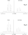
- This covering also serves to shield external light in the frequency range from 570 nm to 1008 nm, in particular from 785+/-215 nm, in which the measuring frequencies lie. This is 785 + 215 nm for the Stokes range and 785 - 215 nm for the anti-Stokes range, see Fig. 5 .
- energy is transferred from the photon (Stokes scattering) to the molecule or from the molecule to the photon (anti-Stokes scattering). Both transitions can be evaluated individually and/or in relation to one another.
- good stability of the measuring signal can be achieved during the measuring time.
- a range of +/- 245 nm is also possible, see Fig. 6 .
- the window in the example is in Fig. 1 to 4 advantageously made of sapphire glass in order to allow the relevant frequency spectra in the range from 570 nm to 1008 nm, in particular from 785+/-215 nm to pass through.
- the relevant frequency spectra in the range from 570 nm to 1008 nm, in particular from 785+/-215 nm to pass through.
- at least the range between 931 nm (Stokes) and 678 nm (Anti-Stokes) should be allowed to pass through.
- the surfaces of the window 21 are flat and aligned parallel to one another.
- the inner surface of the window 21 facing the receiving container 1 can also be concavely adapted to the radius of the receiving container 1 and the outer surface of the window 21 facing away from the receiving container 1 can be designed to be concave parallel to the inner surface.
- the excitation source 11 can be a laser with a wavelength range of 100 to 1400 nm, in the range of infrared, visible and/or UV light, e.g. a wavelength range of 780+/-250 nm.
- Other possible lasers that can be used can cover a wavelength range of 532 +/- 215nm, 638 +/- 215nm, 820 +/- 215nm and/or 1064 +/-215nm.
- the laser power is, for example, in the range of 15 mW to 5 W, with 100 mW to 500 mW being preferred.
- the use of lasers with high energy density is advantageous because the material is constantly exchanged and therefore there is no change in the material being measured. There may be a particular need for high energy densities, for example with very darkly colored polymers.
- the ratio of laser power to integration time must be taken into account. This is preferably in the range of 5 mW/s to 5000 mW/s, especially in the range of 15 mW/s to 1000 mW/s.
- the measuring head 24 of the measuring device 10 arranged at the measuring opening 20 or the window 21 with the lens system 22 in order to remain permanently below 90°C, preferably below 60°C.
- Gases or liquids can be used as cooling media, but a Peltier element can also be used.
- the window can also be made of quartz glass in order to allow the relevant frequency spectra in the range from 760 nm to 2500 nm for NIR to pass through.
- Fiber optic systems are preferred in order to keep the setup simple. Fiber optic systems require the least space directly in front of the window 21. It is possible to couple both measuring devices 10 via one window 21, but also via different windows 21. It has proven to be useful if the windows 21 are largely at the same height in the circumferential direction. Local proximity is desirable, but not necessary.
- the volume range of the material that can be examined is defined by a measuring spot cross-sectional area in the range from 0.1 mm to 5 mm, in particular from 1 mm to 3 mm, and a penetration depth into the material of 0.3 ⁇ m to 30 ⁇ m.
- the penetration depth that leads to good measured values in practice is in the range from 8 ⁇ m to 15 ⁇ m.
- the measuring spot cross-sectional area in the exemplary embodiment is approximately 1 mm to 3 mm, so that a volume of approximately 0.00015 mm 3 can be examined. For this reason, the frequency of the measurement or the frequent movement of the material to be measured past the window 21 is important in order to achieve representative measurement results.
- the processing and control unit 40 derives information about the material being measured, in particular quantitative and/or qualitative parameters of the respective material, on the basis of the measured values determined and makes this available.
- the processing and control unit 40 can spectrometrically and/or spectroscopically analyze the measurement signals generated as a reaction to the impact, in particular characteristic spectra of the electromagnetic radiation scattered on the material being measured.
- the lumpy or particulate material moving inside the receiving container 1 is analyzed or measured inline spectroscopically and/or spectrometrically and the measured values determined in this way are used to obtain information about the material being measured, in particular quantitative and/or qualitative parameters of the respective material.
- the measurement signals generated as a reaction to the electromagnetic radiation are detected and evaluated in the form of characteristic spectra of the electromagnetic radiation scattered by the material being measured, preferably spectrometrically.
- the evaluation of the measurement results or spectra thus obtained is carried out by the processing and control unit 40 and is advantageously carried out as follows: Due to the frequent flow of the material particles in a solid to partially softened state past the measuring position or the focus point 23, it is possible to use long measuring times, which enable the use of, for example, lasers with a low power of approx. 20 - 200 mW, while the meaningfulness of the measurement results remains sufficiently accurate.
- the processing and control unit 40 controls the measuring device 10, or the excitation source 11, in such a way that it measures the physical effect, for example the electromagnetic radiation emitted by the laser, during a predetermined period of time, e.g. from less than one second to several seconds. or one minute or more.
- the processing and control unit 40 then calculates a single, common piece of information about the material being measured for the respective period of time, ie all material particles that have passed through the measuring opening 20 or the window 21 during this period of time and have been detected by the detector 12. For example, a single cumulative spectrum can be created for all of these material particles.
- the processing and control unit 40 can control the measuring device 10 or the excitation source 11 in such a way that it repeatedly emits the physical effect, for example the electromagnetic radiation emitted by the laser, at a large number of predetermined times.
- the processing and control unit 40 can then calculate and keep available an average of the information about the material being measured, based on selected or all measured values determined for individual particles at these times by the measuring device 10, in particular the detector 12. This means that an average is formed from a large number of spectra of individual particles.
- the flow of the material past prevents the material to be measured from being influenced by the high energy density of the laser at the focal point 23.
- an unknown material is excited with a higher energy density and the processing and control unit 40 optionally regulates the laser power downwards until the detector 12 is in its linear range. This automated measuring process could not be used in a static measuring process because the sample or material would burn or melt.
- a device according to the invention can optionally also comprise a temperature measuring device 30 which is connected upstream of the processing and control unit 40.
- a temperature change of the material occurs: the material is fed at room temperature or is introduced into the top of the receiving container 1 and is then, for example, by the movement of the Mixing and/or crushing tools 4 or heated by friction. The material becomes hot, softens, but always remains particle-shaped or lumpy and does not melt.
- this temperature change leads to a change in the spectra recorded by the measuring device 10 or the detector 12 due to the structural change in the polymers in this process step. It is therefore advantageous if an appropriate correction is made during the evaluation, especially if the spectrum recorded in each case is to be compared with existing spectra databases.
- Such an optional temperature measuring device 30 measures the temperature inside the receiving container 1 and/or the temperature of the material and transmits this to the processing and control unit 40.
- the material temperature is recorded, for example, with a temperature sensor that protrudes into the edge layer of the material and is used as a specification for correcting the spectra.
- the container temperature of the receiving container 1 can also be used as a value.
- Another thermal measuring device e.g. of an optical nature, can also be attached to the receiving container 1 in order to record the temperature. In this context, it is particularly advantageous to install the temperature measuring device 30 in close proximity to the window 21 covering the measuring opening 20 or to the measuring head 24 of the measuring device.
- the temperature measuring device 30 can be arranged in the receiving container 1, e.g. at the same height, in particular at the same position, as the at least one measuring opening 20.
- the processing and control unit 40 uses the measured values determined by the one temperature measuring device 30 to correct the temperature influence on the information determined for the respective material being measured, in particular the temperature-dependent characteristic spectra of the electromagnetic radiation scattered by the material being measured, and keeps the information corrected in this way, in particular spectra, available.
- the temperature information obtained in this way is included in the evaluation and serves as an indication for a temperature correction of the spectra.
- the material temperature of the material in the receiving container 1 is measured and sent to the processing and control unit 40. There, the measured actual temperature is used to correct the spectra, e.g. to a reference temperature, in order to enable a simple comparison with stored reference spectra.
- the processing and control unit 40 can comprise a memory in which reference information, e.g. quantitative and/or qualitative reference parameters or reference spectra, is stored. The processing and control unit 40 can then compare the information such as spectra determined for the respective measured material with the reference information, e.g. reference spectra, and determine the deviation from the reference information or reference spectra. This determined deviation can then be forwarded, e.g. to a process control unit and/or a display unit.
- reference information e.g. quantitative and/or qualitative reference parameters or reference spectra
- the processing and control unit 40 interacts with a process control unit 50 and is in data communication with the latter.
- a process control unit is designed according to the invention to use data transmitted by the processing and control unit 40, i.e. information about the respective plastic material being measured, such as quantitative and/or qualitative parameters of the respective material, to monitor and/or control the process control in the receiving container 1 and/or the subsequent process chain.
- a first application example of a method according to the invention or a device according to the invention for preparing, processing and/or Recycling of plastic materials described: Different polymers with different viscosities and filler levels such as CaCOs are used in the manufacture of hygiene products such as diapers, sanitary towels, etc.
- the fleece part of the hygiene products usually consists of unfilled PP and the film of LD-PE filled with CaCOs.
- the punching residues and film residues that arise during production therefore have a different polymer content and a different filler level.
- the end product can be adjusted to a defined mixture by adding polymer, additives and filler, provided the incoming components are absolutely known. This increases flexibility accordingly.
- a measurement before and for control after the compounding step controls the proportions of the added components and thus ensures certain properties and minimizes production costs.
- spectra could be recorded by the detector 12 or the spectroscope.
- the spectra recorded by the detector 12 are in Fig. 7
- the spectra show mixtures of PE and varying percentages of CaCOs (1%, 2%, 5%, 10%, 15%, 17.5%, 20% CaCOs).
- the acquired spectra are evaluated by the processing and control unit 40 with regard to the proportion of CaCOs and the proportion of CaCOs is provided by the processing and control unit 40 in % of the total material.
- a control signal can thus be derived to a process control unit 50 connected to the processing and control unit 40, such as a dosing unit, on the basis of which the supply of CaCOs in powder form or as a masterbatch is adapted accordingly. If the proportion in the input material is higher, the dosing quantity can be reduced accordingly and if the proportion in the input material is lower, it can be increased.
- the end product produced then advantageously has a uniform CaCOs proportion.
- a CaCOs proportion of approx. 15% - 25% is provided for injection molded products, depending on the application, whereby the deviation may only be +/- 1% in each case.
- a second application example of a method or device according to the invention is described below:
- the different polymer streams are separated and cleaned as best as possible through sorting and washing processes.
- thermal forming process both homogenization and melt filtration are carried out.
- the regenerated materials produced from this must meet a certain quality depending on the application: For example, when producing blown film from LD-PE, the proportion of PP should not exceed a certain percentage, as the desired mechanical properties may then not be achieved. be achieved or the weldability may no longer be ensured.
- An INTAREMA ® 80TVEplus comprising a measuring device 10 with a detector 12 for RAMAN spectroscopy and a receiving container 1, i.e. a cutter-compactor or a preconditioning unit, was used for the test.
- a measuring device based on RAMAN spectroscopy which repeatedly carries out measurements at predetermined time intervals, was demonstrated by adding PE film to a pure PP film in the receiving container 1.
- two film rolls, one PP roll and one LDPe roll, with a known film width and film thickness were fed into the receiving container 1 via a separate feed value.
- the percentage distribution was calculated from the basis weight and confirmed by random testing of the granulate produced.
- Table 2 The test data are summarized in Table 2.
- Table 2 Test data second application example (the term “INTAREMA” used in the table refers to “INTAREMA ⁇ sup>® ⁇ /sup>”) material machine PCU temperature PCU performance tool speed laser intensity integration period number of measurements measurement time per spectrum [°C] [kW] [rpm] [mW] [s] [s] PE/PP INTAREMA 1108 TVEplus 100 40-41 750 150 4 10 40
- the spectra recorded by the detector 12 are in Fig. 9
- the spectra show mixtures of PP and PE with varying percentages (100%, 90%, 70%, 50%, 25%, 10% 0% PP).
- the acquired spectra are evaluated by the processing and control unit 40 and the proportion of PP is provided in % of the total material by the processing and control unit 40, see Fig. 10 .
- PE/PA composites are used as packaging film for food.
- This is a multi-layer structure, in the middle of which is the PA film, which functions as aroma protection, for example.
- PE polyethylene
- PA polyamide
- compatibilizers are polymers that do not mix well.
- compatibilizers are very expensive and the proportions of PA and PE vary, costs can be saved during processing and the end product optimized if the polymer proportion is precisely determined and the addition of the compatibilizer can be controlled accordingly.
- the residual materials usually have a proportion of around 40% PA and 60% PE and are available in flat structures, edge strips and film rolls.
- An INTAREMA ® 1108 TE comprising a measuring device 10 with a detector 12 for RAMAN spectroscopy and a receiving container 1, i.e. a cutting compactor or a preconditioning unit, was used for the test.
- a continuously measuring measuring device 10 based on RAMAN spectroscopy was demonstrated by adding the PE/PA edge strips and film pieces to the receiving container 1.
- the corresponding polymer proportions in the granulate produced were measured using laboratory measuring devices for control of the previously determined inline proportions.
- Table 3 The test data are summarized in Table 3.
- Test data third application example (the term “INTAREMA” used in the table refers to “INTAREMA ⁇ sup>® ⁇ /sup>") material machine PCU temperature PCU performance tool speed laser intensity integration period number of measurements measurement time per spectrum [°C] [kW] [rpm] [mW] [s] [s] PE/PA INTAREMA 1108 TE 107 48-54 750 350 3 10 30
- the spectra recorded by the detector 12 are evaluated by the processing and control unit 40 and the proportion of PA to PE is displayed by the processing and control unit 40, see Fig. 11 .
- the PE content increases at around 9:55.
- this is not desirable in order to achieve the desired end quality of the end product, as too low a PA content negatively affects the properties of the end product and, in addition, too much compatibilizer is added.
- a switch in response to the information determined about the measured material, a switch can be connected to the end of the processing plant and the granulate produced can be discharged in the range from 9:55 to 10:08.
- the above-described device according to the invention or the above-described method according to the invention thus enables effective inline process analysis, monitoring and, if necessary, control in systems for preparing, processing and/or recycling plastic materials, with a receiving container 1, ie a cutter-compactor or a cutter-compactor-extruder combination, using spectroscopic and/or spectrometric measuring devices 10.
- the information/data transmitted by the evaluation unit can also be used in the subsequent process chain, such as when adding fillers, discharging finished granulate, but also when feeding other polymers, e.g. into the receiving container 1, i.e. the cutter-compactor or the cutter-compactor-extruder combination.
Landscapes
- Health & Medical Sciences (AREA)
- Chemical & Material Sciences (AREA)
- Physics & Mathematics (AREA)
- Life Sciences & Earth Sciences (AREA)
- Engineering & Computer Science (AREA)
- Pathology (AREA)
- Analytical Chemistry (AREA)
- Biochemistry (AREA)
- General Health & Medical Sciences (AREA)
- General Physics & Mathematics (AREA)
- Immunology (AREA)
- Environmental & Geological Engineering (AREA)
- Mechanical Engineering (AREA)
- Spectroscopy & Molecular Physics (AREA)
- Medicinal Chemistry (AREA)
- Nuclear Medicine, Radiotherapy & Molecular Imaging (AREA)
- Food Science & Technology (AREA)
- Sustainable Development (AREA)
- Polymers & Plastics (AREA)
- Organic Chemistry (AREA)
- Chemical Kinetics & Catalysis (AREA)
- Investigating Or Analysing Materials By Optical Means (AREA)
- Investigating, Analyzing Materials By Fluorescence Or Luminescence (AREA)
- Separation, Recovery Or Treatment Of Waste Materials Containing Plastics (AREA)
- Processing And Handling Of Plastics And Other Materials For Molding In General (AREA)
- Processing Of Solid Wastes (AREA)
Priority Applications (1)
| Application Number | Priority Date | Filing Date | Title |
|---|---|---|---|
| SI201930896T SI4119320T1 (sl) | 2018-08-29 | 2019-08-28 | Postopek in naprava za pripravo, predelavo in/ali recikliranje plastičnih materialov |
Applications Claiming Priority (3)
| Application Number | Priority Date | Filing Date | Title |
|---|---|---|---|
| AT507382018 | 2018-08-29 | ||
| PCT/AT2019/060278 WO2020041813A1 (de) | 2018-08-29 | 2019-08-28 | Verfahren und vorrichtung zum aufbereiten, bearbeiten und/oder recyceln von materialien |
| EP19762701.1A EP3843966B1 (de) | 2018-08-29 | 2019-08-28 | Verfahren und vorrichtung zum aufbereiten, bearbeiten und/oder recyceln von thermoplastischen kunststoffmaterialien |
Related Parent Applications (2)
| Application Number | Title | Priority Date | Filing Date |
|---|---|---|---|
| EP19762701.1A Division EP3843966B1 (de) | 2018-08-29 | 2019-08-28 | Verfahren und vorrichtung zum aufbereiten, bearbeiten und/oder recyceln von thermoplastischen kunststoffmaterialien |
| EP19762701.1A Division-Into EP3843966B1 (de) | 2018-08-29 | 2019-08-28 | Verfahren und vorrichtung zum aufbereiten, bearbeiten und/oder recyceln von thermoplastischen kunststoffmaterialien |
Publications (2)
| Publication Number | Publication Date |
|---|---|
| EP4119320A1 EP4119320A1 (de) | 2023-01-18 |
| EP4119320B1 true EP4119320B1 (de) | 2024-11-27 |
Family
ID=67847562
Family Applications (2)
| Application Number | Title | Priority Date | Filing Date |
|---|---|---|---|
| EP22192112.5A Active EP4119320B1 (de) | 2018-08-29 | 2019-08-28 | Verfahren und vorrichtung zum aufbereiten, bearbeiten und/oder recyceln von kunststoffmaterialien |
| EP19762701.1A Active EP3843966B1 (de) | 2018-08-29 | 2019-08-28 | Verfahren und vorrichtung zum aufbereiten, bearbeiten und/oder recyceln von thermoplastischen kunststoffmaterialien |
Family Applications After (1)
| Application Number | Title | Priority Date | Filing Date |
|---|---|---|---|
| EP19762701.1A Active EP3843966B1 (de) | 2018-08-29 | 2019-08-28 | Verfahren und vorrichtung zum aufbereiten, bearbeiten und/oder recyceln von thermoplastischen kunststoffmaterialien |
Country Status (17)
| Country | Link |
|---|---|
| US (1) | US12377581B2 (da) |
| EP (2) | EP4119320B1 (da) |
| JP (1) | JP7369765B2 (da) |
| KR (1) | KR102880092B1 (da) |
| CN (1) | CN112912220B (da) |
| AU (2) | AU2019329926B2 (da) |
| BR (1) | BR112021003619B1 (da) |
| CA (1) | CA3110716A1 (da) |
| DK (2) | DK3843966T3 (da) |
| ES (2) | ES3010164T3 (da) |
| HU (2) | HUE060862T2 (da) |
| MX (1) | MX2021002331A (da) |
| PL (2) | PL4119320T3 (da) |
| PT (2) | PT4119320T (da) |
| SI (2) | SI4119320T1 (da) |
| WO (1) | WO2020041813A1 (da) |
| ZA (1) | ZA202101522B (da) |
Families Citing this family (5)
| Publication number | Priority date | Publication date | Assignee | Title |
|---|---|---|---|---|
| US11878327B2 (en) | 2019-03-13 | 2024-01-23 | Digimarc Corporation | Methods and arrangements for sorting items, useful in recycling |
| CN113499707A (zh) * | 2021-07-13 | 2021-10-15 | 上海爱尔企业发展股份有限公司 | 一种纺织助剂配料预加工的锥形混合机入料设备 |
| CN114558881B (zh) * | 2022-03-10 | 2022-12-09 | 广东省车汇莱再生物资回收有限公司 | 一种基于智能化的新能源报废汽车资源化回收系统 |
| CN115709212B (zh) * | 2022-11-21 | 2024-09-17 | 海南大学 | 一种用于研究塑料生物降解的实验装置 |
| WO2026007095A1 (en) | 2024-07-05 | 2026-01-08 | Carl Zeiss Vision International Gmbh | Pretreatment of thermosetting spectacle lens wastes for recycling |
Family Cites Families (21)
| Publication number | Priority date | Publication date | Assignee | Title |
|---|---|---|---|---|
| AT375867B (de) | 1983-04-27 | 1984-09-25 | Erema | Vorrichtung zum aufbereiten von thermoplastischem kunststoffgut |
| JPS62250333A (ja) | 1986-04-24 | 1987-10-31 | Toonichi Consultant:Kk | 懸濁液光学測定装置 |
| DE3922902A1 (de) * | 1989-07-12 | 1991-01-17 | Hoechst Ag | Verfahren zur herstellung einer farbigen kunststoff-formmasse |
| JP3045304B2 (ja) | 1990-11-30 | 2000-05-29 | 東ソー株式会社 | ポリフェニレンスルフィド樹脂組成物 |
| JPH0732363B2 (ja) | 1991-04-23 | 1995-04-10 | 川崎製鉄株式会社 | 半導体集積回路 |
| JPH0732363A (ja) * | 1993-07-16 | 1995-02-03 | Matsui Mfg Co | 粉粒体の混合装置とこの混合装置を備えた樹脂成形機 |
| JPH10185817A (ja) | 1996-12-26 | 1998-07-14 | Mitsubishi Heavy Ind Ltd | レーザを用いた組成成分計測方法 |
| AU2001240121B2 (en) * | 2000-03-10 | 2005-06-23 | Textron Systems Corporation | Optical probes and methods for spectral analysis |
| DE10024309A1 (de) | 2000-05-17 | 2001-11-29 | Der Gruene Punkt Duales Syst | Verfahren und Vorrichtung zur trockenen Auftrennung von Sammelmüll mit Verpackungsabfällen |
| JP4579466B2 (ja) | 2000-08-25 | 2010-11-10 | テクノポリマー株式会社 | 樹脂リサイクルシステム |
| US10188119B2 (en) | 2001-07-16 | 2019-01-29 | Foret Plasma Labs, Llc | Method for treating a substance with wave energy from plasma and an electrical arc |
| WO2005049663A2 (en) | 2002-10-15 | 2005-06-02 | Exxonmobil Chemical Patents Inc. | On-line measurement and control of polymer properties by raman spectroscopy |
| JP5207391B2 (ja) | 2009-03-09 | 2013-06-12 | シャープ株式会社 | プラスチック部材の製造方法 |
| WO2011088488A1 (de) | 2010-01-22 | 2011-07-28 | Erema Engineering Recycling Maschinen Und Anlagen Gesellschaft M.B.H. | Verfahren zur aufbereitung und entgiftung |
| AT511362B1 (de) | 2010-04-14 | 2014-01-15 | Erema | Vorrichtung zum aufbereiten von kunststoffmaterial |
| AT512209B1 (de) | 2011-10-14 | 2015-02-15 | Erema | Vorrichtung zum aufbereiten von kunststoffmaterial |
| JP6016457B2 (ja) | 2012-05-30 | 2016-10-26 | キヤノン株式会社 | 現像装置およびプロセスカートリッジ |
| CN203427220U (zh) * | 2013-08-21 | 2014-02-12 | 武汉力富特液压科技有限公司 | 新型废塑料混合分选机 |
| US9945790B2 (en) * | 2015-08-05 | 2018-04-17 | Viavi Solutions Inc. | In-situ spectral process monitoring |
| WO2017051424A1 (en) * | 2015-09-25 | 2017-03-30 | Verifood Ltd. | Spectral blender |
| EP3537119B1 (de) * | 2018-03-06 | 2022-09-28 | Vorwerk & Co. Interholding GmbH | System mit einem speisenzubereitungsgerät und einem spektrometer |
-
2019
- 2019-08-28 ES ES22192112T patent/ES3010164T3/es active Active
- 2019-08-28 AU AU2019329926A patent/AU2019329926B2/en active Active
- 2019-08-28 US US17/271,493 patent/US12377581B2/en active Active
- 2019-08-28 MX MX2021002331A patent/MX2021002331A/es unknown
- 2019-08-28 WO PCT/AT2019/060278 patent/WO2020041813A1/de not_active Ceased
- 2019-08-28 DK DK19762701.1T patent/DK3843966T3/da active
- 2019-08-28 EP EP22192112.5A patent/EP4119320B1/de active Active
- 2019-08-28 CA CA3110716A patent/CA3110716A1/en active Pending
- 2019-08-28 PT PT221921125T patent/PT4119320T/pt unknown
- 2019-08-28 SI SI201930896T patent/SI4119320T1/sl unknown
- 2019-08-28 SI SI201930409T patent/SI3843966T1/sl unknown
- 2019-08-28 CN CN201980071366.9A patent/CN112912220B/zh active Active
- 2019-08-28 EP EP19762701.1A patent/EP3843966B1/de active Active
- 2019-08-28 ES ES19762701T patent/ES2932378T3/es active Active
- 2019-08-28 BR BR112021003619-9A patent/BR112021003619B1/pt active IP Right Grant
- 2019-08-28 HU HUE19762701A patent/HUE060862T2/hu unknown
- 2019-08-28 PL PL22192112.5T patent/PL4119320T3/pl unknown
- 2019-08-28 HU HUE22192112A patent/HUE071038T2/hu unknown
- 2019-08-28 PL PL19762701.1T patent/PL3843966T3/pl unknown
- 2019-08-28 PT PT197627011T patent/PT3843966T/pt unknown
- 2019-08-28 JP JP2021510399A patent/JP7369765B2/ja active Active
- 2019-08-28 KR KR1020217008832A patent/KR102880092B1/ko active Active
- 2019-08-28 DK DK22192112.5T patent/DK4119320T3/da active
-
2021
- 2021-03-05 ZA ZA2021/01522A patent/ZA202101522B/en unknown
-
2025
- 2025-04-04 AU AU2025202427A patent/AU2025202427A1/en active Pending
Also Published As
| Publication number | Publication date |
|---|---|
| JP7369765B2 (ja) | 2023-10-26 |
| ES2932378T3 (es) | 2023-01-18 |
| HUE060862T2 (hu) | 2023-04-28 |
| US12377581B2 (en) | 2025-08-05 |
| AU2019329926B2 (en) | 2025-04-24 |
| PL4119320T3 (pl) | 2025-03-24 |
| ES3010164T3 (en) | 2025-04-01 |
| EP4119320A1 (de) | 2023-01-18 |
| CN112912220A (zh) | 2021-06-04 |
| KR20210047929A (ko) | 2021-04-30 |
| HUE071038T2 (hu) | 2025-07-28 |
| DK3843966T3 (da) | 2023-01-09 |
| CN112912220B (zh) | 2023-06-27 |
| PT4119320T (pt) | 2025-02-03 |
| EP3843966B1 (de) | 2022-10-05 |
| SI4119320T1 (sl) | 2025-07-31 |
| BR112021003619A2 (pt) | 2021-05-18 |
| PT3843966T (pt) | 2022-12-06 |
| US20210197421A1 (en) | 2021-07-01 |
| AU2019329926A1 (en) | 2021-04-15 |
| SI3843966T1 (sl) | 2023-02-28 |
| BR112021003619B1 (pt) | 2024-04-30 |
| KR102880092B1 (ko) | 2025-11-03 |
| EP3843966A1 (de) | 2021-07-07 |
| ZA202101522B (en) | 2022-06-29 |
| JP2022501578A (ja) | 2022-01-06 |
| CA3110716A1 (en) | 2020-03-05 |
| AU2025202427A1 (en) | 2025-05-01 |
| DK4119320T3 (da) | 2025-03-03 |
| PL3843966T3 (pl) | 2023-03-20 |
| MX2021002331A (es) | 2021-08-11 |
| WO2020041813A1 (de) | 2020-03-05 |
Similar Documents
| Publication | Publication Date | Title |
|---|---|---|
| EP4119320B1 (de) | Verfahren und vorrichtung zum aufbereiten, bearbeiten und/oder recyceln von kunststoffmaterialien | |
| Coates et al. | In-process vibrational spectroscopy and ultrasound measurements in polymer melt extrusion | |
| Ryder et al. | Identifications and quantitative measurements of narcotics in solid mixtures using near-IR Raman spectroscopy and multivariate analysis | |
| Dumitrescu et al. | Near infrared spectroscopy for in-line monitoring during injection moulding | |
| EP2756029B1 (de) | Gefärbte polymere folie, verfahren und vorrichtung zur herstellung der folie | |
| Becker et al. | Turbidimetric method for the determination of particle sizes in polypropylene/clay-composites during extrusion | |
| DE102008019176A1 (de) | Verfahren und Vorrichtung zur Herstellung von Kunststoffbehältnissen mit Infrarot-Absorptionsüberwachung | |
| Barnes et al. | Vibrational spectroscopic and ultrasound analysis for in-process characterization of high-density polyethylene/polypropylene blends during melt extrusion | |
| WO2024079019A2 (de) | Verfahren und vorrichtung zur berührungslosen temperaturbestimmung eines fördergutstroms sowie granuliereinrichtung mit einer solchen berührungslosen temperaturbestimmungsvorrichtung | |
| RU2805333C2 (ru) | Способ и устройство для подготовки, обработки и/или рециклинга материалов | |
| DE10318892A1 (de) | System und Verfahren zur fortlaufenden Referenzierung von Reflektionsmessungen zur Kontrolle von flüssigen oder rieselfähigen Gütern | |
| EP3322983A1 (de) | VERFAHREN ZUR AUFBEREITUNG VON ERSATZBRENNSTOFF SOWIE EIN VERFAHREN ZUR ANSCHLIEßENDEN ANALYSE DES ERSATZBRENNSTOFFS | |
| Ishikawa et al. | Near‐Infrared Spectroscopy and Imaging of Polymers | |
| Becker et al. | Near infrared spectroscopy as a tool for in-line control of process and material properties of PLA biopolymer | |
| WO2009040291A1 (de) | Verfahren und vorrichtung zur messung von farbeigenschaften von kunststoffgranulaten | |
| Becker et al. | Measurement of the Irganox content in polypropylene polymers during extrusion | |
| EP1069415B1 (de) | Verfahren und Vorrichtung zur spektroskopischen Untersuchung von plastifizierten Extrudaten | |
| DE102005036643A1 (de) | Verfahren und Vorrichtung zur Ermittlung des Reifezustandes von Duroplast-Zusammensetzungen | |
| WO2025237913A1 (en) | Method for calibration, method for in-line quality control in a compounding process based on nir and apparatus with nir quality control | |
| Ďurčová et al. | Contribution to the quantitative IR analysis of modified polypropylene fibres | |
| DE102020108079A1 (de) | Erfassungsvorrichtung zur Erfassung wenigstens eines Parameters von Baumaterial | |
| Eisenreich et al. | On-Line Spectroscopy in Extrusion of Polymers and Composites | |
| Lepschi et al. | Effect of Extrusion Parameters on Properties of Powder Coatings Determined by Infrared Spectroscopy | |
| DE102011053479A1 (de) | Messeinrichtung, Fertigungsvorrichtung und Verfahren zum Betrieb einer Messeinrichtung zur Bestimmung einer Zusammensetzung eines Materials | |
| DE102014112323A1 (de) | Messung der zukünftigen Färbeeigenschaften bei Spinnfäden |
Legal Events
| Date | Code | Title | Description |
|---|---|---|---|
| PUAI | Public reference made under article 153(3) epc to a published international application that has entered the european phase |
Free format text: ORIGINAL CODE: 0009012 |
|
| STAA | Information on the status of an ep patent application or granted ep patent |
Free format text: STATUS: THE APPLICATION HAS BEEN PUBLISHED |
|
| AC | Divisional application: reference to earlier application |
Ref document number: 3843966 Country of ref document: EP Kind code of ref document: P |
|
| AK | Designated contracting states |
Kind code of ref document: A1 Designated state(s): AL AT BE BG CH CY CZ DE DK EE ES FI FR GB GR HR HU IE IS IT LI LT LU LV MC MK MT NL NO PL PT RO RS SE SI SK SM TR |
|
| STAA | Information on the status of an ep patent application or granted ep patent |
Free format text: STATUS: REQUEST FOR EXAMINATION WAS MADE |
|
| 17P | Request for examination filed |
Effective date: 20230718 |
|
| RBV | Designated contracting states (corrected) |
Designated state(s): AL AT BE BG CH CY CZ DE DK EE ES FI FR GB GR HR HU IE IS IT LI LT LU LV MC MK MT NL NO PL PT RO RS SE SI SK SM TR |
|
| GRAP | Despatch of communication of intention to grant a patent |
Free format text: ORIGINAL CODE: EPIDOSNIGR1 |
|
| STAA | Information on the status of an ep patent application or granted ep patent |
Free format text: STATUS: GRANT OF PATENT IS INTENDED |
|
| RIC1 | Information provided on ipc code assigned before grant |
Ipc: G01N 21/84 20060101ALN20240607BHEP Ipc: G01N 21/33 20060101ALN20240607BHEP Ipc: G01N 21/359 20140101ALN20240607BHEP Ipc: G01N 33/44 20060101ALI20240607BHEP Ipc: G01N 21/85 20060101ALI20240607BHEP Ipc: G01N 21/65 20060101ALI20240607BHEP Ipc: G01N 21/64 20060101ALI20240607BHEP Ipc: G01N 21/51 20060101ALI20240607BHEP Ipc: G01N 21/31 20060101ALI20240607BHEP Ipc: B29B 17/04 20060101ALI20240607BHEP Ipc: B29B 17/00 20060101AFI20240607BHEP |
|
| INTG | Intention to grant announced |
Effective date: 20240624 |
|
| GRAS | Grant fee paid |
Free format text: ORIGINAL CODE: EPIDOSNIGR3 |
|
| GRAA | (expected) grant |
Free format text: ORIGINAL CODE: 0009210 |
|
| STAA | Information on the status of an ep patent application or granted ep patent |
Free format text: STATUS: THE PATENT HAS BEEN GRANTED |
|
| AC | Divisional application: reference to earlier application |
Ref document number: 3843966 Country of ref document: EP Kind code of ref document: P |
|
| AK | Designated contracting states |
Kind code of ref document: B1 Designated state(s): AL AT BE BG CH CY CZ DE DK EE ES FI FR GB GR HR HU IE IS IT LI LT LU LV MC MK MT NL NO PL PT RO RS SE SI SK SM TR |
|
| REG | Reference to a national code |
Ref country code: GB Ref legal event code: FG4D Free format text: NOT ENGLISH |
|
| REG | Reference to a national code |
Ref country code: CH Ref legal event code: EP |
|
| REG | Reference to a national code |
Ref country code: DE Ref legal event code: R096 Ref document number: 502019012572 Country of ref document: DE |
|
| REG | Reference to a national code |
Ref country code: IE Ref legal event code: FG4D Free format text: LANGUAGE OF EP DOCUMENT: GERMAN |
|
| REG | Reference to a national code |
Ref country code: PT Ref legal event code: SC4A Ref document number: 4119320 Country of ref document: PT Date of ref document: 20250203 Kind code of ref document: T Free format text: AVAILABILITY OF NATIONAL TRANSLATION Effective date: 20250127 |
|
| REG | Reference to a national code |
Ref country code: DK Ref legal event code: T3 Effective date: 20250225 |
|
| REG | Reference to a national code |
Ref country code: NL Ref legal event code: FP |
|
| REG | Reference to a national code |
Ref country code: SE Ref legal event code: TRGR |
|
| REG | Reference to a national code |
Ref country code: LT Ref legal event code: MG9D |
|
| REG | Reference to a national code |
Ref country code: ES Ref legal event code: FG2A Ref document number: 3010164 Country of ref document: ES Kind code of ref document: T3 Effective date: 20250401 |
|
| REG | Reference to a national code |
Ref country code: SK Ref legal event code: T3 Ref document number: E 45970 Country of ref document: SK |
|
| PG25 | Lapsed in a contracting state [announced via postgrant information from national office to epo] |
Ref country code: HR Free format text: LAPSE BECAUSE OF FAILURE TO SUBMIT A TRANSLATION OF THE DESCRIPTION OR TO PAY THE FEE WITHIN THE PRESCRIBED TIME-LIMIT Effective date: 20241127 Ref country code: IS Free format text: LAPSE BECAUSE OF FAILURE TO SUBMIT A TRANSLATION OF THE DESCRIPTION OR TO PAY THE FEE WITHIN THE PRESCRIBED TIME-LIMIT Effective date: 20250327 |
|
| PG25 | Lapsed in a contracting state [announced via postgrant information from national office to epo] |
Ref country code: FI Free format text: LAPSE BECAUSE OF FAILURE TO SUBMIT A TRANSLATION OF THE DESCRIPTION OR TO PAY THE FEE WITHIN THE PRESCRIBED TIME-LIMIT Effective date: 20241127 |
|
| PG25 | Lapsed in a contracting state [announced via postgrant information from national office to epo] |
Ref country code: NO Free format text: LAPSE BECAUSE OF FAILURE TO SUBMIT A TRANSLATION OF THE DESCRIPTION OR TO PAY THE FEE WITHIN THE PRESCRIBED TIME-LIMIT Effective date: 20250227 |
|
| PG25 | Lapsed in a contracting state [announced via postgrant information from national office to epo] |
Ref country code: LV Free format text: LAPSE BECAUSE OF FAILURE TO SUBMIT A TRANSLATION OF THE DESCRIPTION OR TO PAY THE FEE WITHIN THE PRESCRIBED TIME-LIMIT Effective date: 20241127 Ref country code: GR Free format text: LAPSE BECAUSE OF FAILURE TO SUBMIT A TRANSLATION OF THE DESCRIPTION OR TO PAY THE FEE WITHIN THE PRESCRIBED TIME-LIMIT Effective date: 20250228 |
|
| PG25 | Lapsed in a contracting state [announced via postgrant information from national office to epo] |
Ref country code: RS Free format text: LAPSE BECAUSE OF FAILURE TO SUBMIT A TRANSLATION OF THE DESCRIPTION OR TO PAY THE FEE WITHIN THE PRESCRIBED TIME-LIMIT Effective date: 20250227 |
|
| PG25 | Lapsed in a contracting state [announced via postgrant information from national office to epo] |
Ref country code: SM Free format text: LAPSE BECAUSE OF FAILURE TO SUBMIT A TRANSLATION OF THE DESCRIPTION OR TO PAY THE FEE WITHIN THE PRESCRIBED TIME-LIMIT Effective date: 20241127 |
|
| PG25 | Lapsed in a contracting state [announced via postgrant information from national office to epo] |
Ref country code: EE Free format text: LAPSE BECAUSE OF FAILURE TO SUBMIT A TRANSLATION OF THE DESCRIPTION OR TO PAY THE FEE WITHIN THE PRESCRIBED TIME-LIMIT Effective date: 20241127 |
|
| REG | Reference to a national code |
Ref country code: HU Ref legal event code: AG4A Ref document number: E071038 Country of ref document: HU |
|
| REG | Reference to a national code |
Ref country code: DE Ref legal event code: R097 Ref document number: 502019012572 Country of ref document: DE |
|
| PGFP | Annual fee paid to national office [announced via postgrant information from national office to epo] |
Ref country code: NL Payment date: 20250821 Year of fee payment: 7 Ref country code: LU Payment date: 20250822 Year of fee payment: 7 |
|
| PGFP | Annual fee paid to national office [announced via postgrant information from national office to epo] |
Ref country code: HU Payment date: 20250825 Year of fee payment: 7 |
|
| PLBE | No opposition filed within time limit |
Free format text: ORIGINAL CODE: 0009261 |
|
| STAA | Information on the status of an ep patent application or granted ep patent |
Free format text: STATUS: NO OPPOSITION FILED WITHIN TIME LIMIT |
|
| PGFP | Annual fee paid to national office [announced via postgrant information from national office to epo] |
Ref country code: ES Payment date: 20250926 Year of fee payment: 7 Ref country code: PT Payment date: 20250814 Year of fee payment: 7 |
|
| PGFP | Annual fee paid to national office [announced via postgrant information from national office to epo] |
Ref country code: DE Payment date: 20250820 Year of fee payment: 7 Ref country code: DK Payment date: 20250825 Year of fee payment: 7 |
|
| PGFP | Annual fee paid to national office [announced via postgrant information from national office to epo] |
Ref country code: PL Payment date: 20250818 Year of fee payment: 7 Ref country code: TR Payment date: 20250819 Year of fee payment: 7 Ref country code: IT Payment date: 20250825 Year of fee payment: 7 |
|
| PGFP | Annual fee paid to national office [announced via postgrant information from national office to epo] |
Ref country code: BG Payment date: 20250822 Year of fee payment: 7 Ref country code: BE Payment date: 20250820 Year of fee payment: 7 Ref country code: GB Payment date: 20250820 Year of fee payment: 7 |
|
| PGFP | Annual fee paid to national office [announced via postgrant information from national office to epo] |
Ref country code: AT Payment date: 20250808 Year of fee payment: 7 Ref country code: FR Payment date: 20250828 Year of fee payment: 7 |
|
| PGFP | Annual fee paid to national office [announced via postgrant information from national office to epo] |
Ref country code: CH Payment date: 20250901 Year of fee payment: 7 Ref country code: SE Payment date: 20250820 Year of fee payment: 7 |
|
| PGFP | Annual fee paid to national office [announced via postgrant information from national office to epo] |
Ref country code: CZ Payment date: 20250818 Year of fee payment: 7 |
|
| PGFP | Annual fee paid to national office [announced via postgrant information from national office to epo] |
Ref country code: RO Payment date: 20250818 Year of fee payment: 7 |
|
| PGFP | Annual fee paid to national office [announced via postgrant information from national office to epo] |
Ref country code: SK Payment date: 20250818 Year of fee payment: 7 |
|
| PGFP | Annual fee paid to national office [announced via postgrant information from national office to epo] |
Ref country code: SI Payment date: 20250814 Year of fee payment: 7 |
|
| 26N | No opposition filed |
Effective date: 20250828 |