EP4117173B1 - Elektrische rotationsmaschinenvorrichtung - Google Patents
Elektrische rotationsmaschinenvorrichtung Download PDFInfo
- Publication number
- EP4117173B1 EP4117173B1 EP20923445.9A EP20923445A EP4117173B1 EP 4117173 B1 EP4117173 B1 EP 4117173B1 EP 20923445 A EP20923445 A EP 20923445A EP 4117173 B1 EP4117173 B1 EP 4117173B1
- Authority
- EP
- European Patent Office
- Prior art keywords
- current
- phase
- axis
- magnetic pole
- control
- Prior art date
- Legal status (The legal status is an assumption and is not a legal conclusion. Google has not performed a legal analysis and makes no representation as to the accuracy of the status listed.)
- Active
Links
Images













Classifications
-
- H—ELECTRICITY
- H02—GENERATION; CONVERSION OR DISTRIBUTION OF ELECTRIC POWER
- H02K—DYNAMO-ELECTRIC MACHINES
- H02K1/00—Details of the magnetic circuit
- H02K1/06—Details of the magnetic circuit characterised by the shape, form or construction
- H02K1/22—Rotating parts of the magnetic circuit
- H02K1/27—Rotor cores with permanent magnets
-
- H—ELECTRICITY
- H02—GENERATION; CONVERSION OR DISTRIBUTION OF ELECTRIC POWER
- H02K—DYNAMO-ELECTRIC MACHINES
- H02K21/00—Synchronous motors having permanent magnets; Synchronous generators having permanent magnets
- H02K21/12—Synchronous motors having permanent magnets; Synchronous generators having permanent magnets with stationary armatures and rotating magnets
-
- H—ELECTRICITY
- H02—GENERATION; CONVERSION OR DISTRIBUTION OF ELECTRIC POWER
- H02K—DYNAMO-ELECTRIC MACHINES
- H02K29/00—Motors or generators having non-mechanical commutating devices, e.g. discharge tubes or semiconductor devices
- H02K29/03—Motors or generators having non-mechanical commutating devices, e.g. discharge tubes or semiconductor devices with a magnetic circuit specially adapted for avoiding torque ripples or self-starting problems
-
- H—ELECTRICITY
- H02—GENERATION; CONVERSION OR DISTRIBUTION OF ELECTRIC POWER
- H02P—CONTROL OR REGULATION OF ELECTRIC MOTORS, ELECTRIC GENERATORS OR DYNAMO-ELECTRIC CONVERTERS; CONTROLLING TRANSFORMERS, REACTORS OR CHOKE COILS
- H02P21/00—Arrangements or methods for the control of electric machines by vector control, e.g. by control of field orientation
- H02P21/05—Arrangements or methods for the control of electric machines by vector control, e.g. by control of field orientation specially adapted for damping motor oscillations, e.g. for reducing hunting
-
- H—ELECTRICITY
- H02—GENERATION; CONVERSION OR DISTRIBUTION OF ELECTRIC POWER
- H02P—CONTROL OR REGULATION OF ELECTRIC MOTORS, ELECTRIC GENERATORS OR DYNAMO-ELECTRIC CONVERTERS; CONTROLLING TRANSFORMERS, REACTORS OR CHOKE COILS
- H02P21/00—Arrangements or methods for the control of electric machines by vector control, e.g. by control of field orientation
- H02P21/06—Rotor flux based control involving the use of rotor position or rotor speed sensors
-
- H—ELECTRICITY
- H02—GENERATION; CONVERSION OR DISTRIBUTION OF ELECTRIC POWER
- H02P—CONTROL OR REGULATION OF ELECTRIC MOTORS, ELECTRIC GENERATORS OR DYNAMO-ELECTRIC CONVERTERS; CONTROLLING TRANSFORMERS, REACTORS OR CHOKE COILS
- H02P21/00—Arrangements or methods for the control of electric machines by vector control, e.g. by control of field orientation
- H02P21/22—Current control, e.g. using a current control loop
-
- H—ELECTRICITY
- H02—GENERATION; CONVERSION OR DISTRIBUTION OF ELECTRIC POWER
- H02P—CONTROL OR REGULATION OF ELECTRIC MOTORS, ELECTRIC GENERATORS OR DYNAMO-ELECTRIC CONVERTERS; CONTROLLING TRANSFORMERS, REACTORS OR CHOKE COILS
- H02P27/00—Arrangements or methods for the control of AC motors characterised by the kind of supply voltage
- H02P27/04—Arrangements or methods for the control of AC motors characterised by the kind of supply voltage using variable-frequency supply voltage, e.g. inverter or converter supply voltage
- H02P27/06—Arrangements or methods for the control of AC motors characterised by the kind of supply voltage using variable-frequency supply voltage, e.g. inverter or converter supply voltage using DC to AC converters or inverters
-
- H—ELECTRICITY
- H02—GENERATION; CONVERSION OR DISTRIBUTION OF ELECTRIC POWER
- H02P—CONTROL OR REGULATION OF ELECTRIC MOTORS, ELECTRIC GENERATORS OR DYNAMO-ELECTRIC CONVERTERS; CONTROLLING TRANSFORMERS, REACTORS OR CHOKE COILS
- H02P6/00—Arrangements for controlling synchronous motors or other dynamo-electric motors using electronic commutation dependent on the rotor position; Electronic commutators therefor
- H02P6/10—Arrangements for controlling torque ripple, e.g. providing reduced torque ripple
-
- H—ELECTRICITY
- H02—GENERATION; CONVERSION OR DISTRIBUTION OF ELECTRIC POWER
- H02P—CONTROL OR REGULATION OF ELECTRIC MOTORS, ELECTRIC GENERATORS OR DYNAMO-ELECTRIC CONVERTERS; CONTROLLING TRANSFORMERS, REACTORS OR CHOKE COILS
- H02P6/00—Arrangements for controlling synchronous motors or other dynamo-electric motors using electronic commutation dependent on the rotor position; Electronic commutators therefor
- H02P6/14—Electronic commutators
- H02P6/16—Circuit arrangements for detecting position
-
- B—PERFORMING OPERATIONS; TRANSPORTING
- B62—LAND VEHICLES FOR TRAVELLING OTHERWISE THAN ON RAILS
- B62D—MOTOR VEHICLES; TRAILERS
- B62D5/00—Power-assisted or power-driven steering
- B62D5/04—Power-assisted or power-driven steering electrical, e.g. using an electric servo-motor connected to, or forming part of, the steering gear
- B62D5/0403—Power-assisted or power-driven steering electrical, e.g. using an electric servo-motor connected to, or forming part of, the steering gear characterised by constructional features, e.g. common housing for motor and gear box
Definitions
- the present disclosure relates to a rotary electric machine apparatus.
- the DC motor which receives supply of DC voltage, generates torque and rotates became popular.
- the DC motor has a problem in maintenance due to abrasion of the brush fundamentally.
- the inverter which can generate the voltages of variable amplitude and variable frequency became popular, the AC motor becomes popular as the motor for variable speed.
- the induction motor became popular first, especially its rotor consists of core and short circuit ring (secondary conductor), and the cage type induction motor which has the cage shape becomes popular.
- the permanent magnet synchronous motor which uses the permanent magnet also becomes popular.
- the induction motor and the permanent magnet synchronous motor which become popular as the AC motor are controlled by technology called “vector control" in many cases.
- vector control current is controlled on the dq-axis rotating coordinate system which rotates synchronizing with the rotor of the AC motor.
- the torque of the AC motor is controlled by controlling the q-axis current which is the q-axis component of the current vector, and the torque response equivalent to the DC motor is realized.
- the rotor of the AC motor has a skew structure.
- the purpose of having the skew structure is to reduce the torque ripple component generated by the AC motor (the cogging torque is also included in the torque ripple component in the permanent magnet synchronous motor) .
- the skew structure is configured so that the position in the circumferential direction of the short circuit ring (secondary conductor) of the rotor shifts continuously at each position in the axial direction.
- the permanent magnet of the rotor has the skew structure in which the magnetic pole position in the circumferential direction is shifted step wisely or continuously at each position in the axial direction.
- the cage type induction motor does not depend on whether or not the skew structure is provided. This is because, in the induction motor, fundamentally, the magnetic flux is generated in the rotor by energizing current to the stator coil, and the magnetic flux direction of the rotor can be generated by energizing current in the direction where the controller intends.
- JP 2015-073 396 A relates to a control apparatus and control method of an electric motor correcting a magnetic pole position by a correction value based on the temperature of the permanent magnets of the rotor.
- the magnetic flux of the rotor is determined by the magnetic pole of the rotor. Accordingly, the direction of the magnetic flux of the rotor cannot be freely changed by the controller. If the permanent magnet of the rotor of the permanent magnet synchronous motor does not have the skew structure, since the position of the circumferential direction of the magnetic pole is the same at each position in the axial direction, the direction of its magnetic pole position may be defined as the d-axis, and the vector control may be performed.
- the permanent magnet of the rotor of the permanent magnet synchronous motor has the skew structure
- the position in the circumferential direction of the magnetic pole changes at each position in the axial direction. Accordingly, when the current control is performed by the dq-axis rotating coordinate system, it becomes a problem how the magnetic pole position corresponding to the d-axis is set.
- the skew structure is provided in order to reduce the torque ripple component, it is not disclosed yet how the magnetic pole position corresponding to the d-axis is set and the vector control is performed in order to reduce the torque ripple component effectively.
- the purpose of the present disclosure is to provide a rotary electric machine apparatus which can perform current control which reduces a torque ripple component effectively, using a rotary electric machine in which the permanent magnet of the rotor has the skew structure which shifts the magnetic pole position in the circumferential direction at each position in the axial direction.
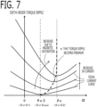
- the magnetic saturation occurs in the stator part which opposes to the magnetic pole position of the most advanced phase and the interlinkage flux of d-axis increases, but its inclination decreases. If this magnetic saturation occurs, the torque ripple component increases. Accordingly, when the winding currents are large, it is necessary to bring the controlling current vector close to the current vector of most advanced phase, in order to suppress that the d-axis current of the most advanced phase increases in the positive direction.
- the controlling current vector is brought close to the current vector of most advanced phase from the current vector of middle phase, as the winding currents increase.
- the torque ripple component generated by the magnetic pole of the most advanced phase and the torque ripple component generated by the magnetic pole of the most delayed phase are canceled with each other, and the torque ripple component can be reduced.
- the d-axis current of the most advanced phase can be suppressed from increasing until the magnetic saturation occurs, and the torque ripple component can be reduced. Accordingly, the phase of the current vector with respect to the magnetic pole position which is shifted in the circumferential direction is changed appropriately according to increase and decrease in the winding currents, and the torque ripple component can be reduced effectively.
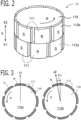
- FIG. 1 is a schematic configuration diagram of the rotary electric machine apparatus according to the present embodiment.
- the rotary electric machine apparatus is provided with a rotary electric machine 1, an inverter 4, and a controller 6.
- the rotary electric machine 1 is a permanent magnet synchronous motor which is provided with a rotor 11 having permanent magnets 111, and a stator 21 having plural-phase windings.
- a rotor 11 having permanent magnets 111
- a stator 21 having plural-phase windings.
- As the plural-phase windings three-phase windings Cu, Cv, Cw of U phase, V phase, and W phase are provided.
- the three-phase windings may be connected by star connection, or may be connected by ⁇ connection.
- the rotor 11 is provided with a rotation detector 2 for detecting a rotational angle of the rotor 11.
- Resolver, encoder, or MR sensor is used for the rotation detector 2.
- An output signal of the rotation detector 2 is inputted into the controller 6.
- the permanent magnets 111 are provided on the surface of the rotor 11, and is a surface magnet type synchronous motor.
- the rotor 11 is provided with a rotor core 110 of cylindrical columnar, and the permanent magnets 111 are stuck on the outer circumferential face of the rotor core 110.
- the permanent magnets 11 have a skew structure in which the magnetic pole positions are shifted in the circumferential direction at each position in the axial direction X.
- the permanent magnets 11 have the skew structure in which the magnetic pole positions are shifted in the circumferential direction in two steps in the axial direction X.
- a first skew step 112a is provided in the axial direction one side X1 of the rotor 11, and a second skew step 112b is provided in the axial direction the other side X2.
- FIG. 2 is a perspective view of the rotor 11, the left side of FIG. 3 is a cross-sectional view of the first skew step 112a, and the right side of FIG.
- FIG 3 is a cross-sectional view of the second skew step 112b.
- eight magnetic poles 111 are disposed at equal intervals in the circumferential direction.
- the N pole and the S pole are disposed alternately in the circumferential direction.
- the magnetic poles 111 (for example, N poles) of the second skew step 112b and the magnetic poles 111 (for example, N poles) of the first skew step 112a are shifted in the circumferential direction with each other.
- the magnetic poles 111 of the second skew step 112b are shifted by 30 degrees in the rotation direction R in the electrical angle with respect to the magnetic poles 111 of the first skew step 112a, and are shifted 7.5 degrees in the mechanical angle.
- a skew angle ⁇ e which is a shift angle in the circumferential direction of the magnetic pole positions is 30 degrees in the electrical angle, and is 7.5 degrees in the mechanical angle.
- the electrical angle becomes an angle obtained by multiplying the number of pole pairs (in this example, 4) to the mechanical angle.
- the number of pole pairs becomes 1/2 of the pole number.
- FIG. 4 is a cross-sectional view of the rotor 11 and the stator 21.
- the number of slots 212 of the stator around which the three-phase windings 211 are wound is 12.
- the rotary electric machine 1 is the surface magnet type permanent magnet synchronous motor of the pole number of 8 and the slot number of 12.
- the inverter 4 is an electric power converter which converts DC power supplied from a DC power source 3 and AC power supplied to the three-phase windings, and is provided with a plurality of switching devices.
- the inverter 4 is provided with three sets of series circuits (leg) in each of which a positive electrode side switching device SP connected to a positive electrode side of the DC power source 3 and a negative electrode side switching device SN connected to a negative electrode side of the DC power source 3 are connected in series, corresponding to respective phase of three-phase.
- a connection node of two switching devices in the series circuit of each phase is connected to the winding of the corresponding phase.
- the positive electrode side switching device SPu of U phase and the negative electrode side switching device SNu of U phase are connected in series, and the connection node of two switching devices is connected to the winding Cu of U phase.
- the positive electrode side switching device SPv of V phase and the negative electrode side switching device SNv of V phase are connected in series, and the connection node of two switching devices is connected to the winding Cv of V phase.
- the positive electrode side switching device SPw of W phase and the negative electrode side switching device SNw of W phase are connected in series, and the connection node of two switching devices is connected to the winding Cw of W phase.
- IGBT Insulated Gate Bipolar Transistor
- MOSFET Metal Oxide Semiconductor Field Effect Transistor
- bipolar transistor in which a diode is connected in reversely parallel, or the like is used for the switching devices.
- a gate terminal of each switching device is connected to the controller 6 via a gate drive circuit and the like. The each switching device is turned on or turned off by the switching signals GPu to GNw outputted from the controller 6.
- the DC power source 3 outputs a power source voltage Vdc to the inverter 4.
- the DC power source 3 may be any apparatus which outputs power source voltage Vdc, such as a battery, a DC-DC converter, a diode rectifier, and a PWM rectifier.
- a voltage sensor which detects the power source voltage Vdc may be provided in the DC power source 3. And, an output signal of the voltage sensor may be inputted into the controller 6.
- the controller 6 may control using the detected power source voltage Vdc.
- the current detector 5 is a circuit which detects currents which flow into the three-phase windings.
- the current detector 5 is provided in the series circuit of two switching devices of each phase of three-phase.
- the current detector 5 is provided with shunt resistances 5u, 5v, 5w connected in series to the negative electrode side of the negative electrode side switching device of each phase.
- the shunt resistance 5u of U phase is connected in series to the negative electrode side of the negative electrode side switching device SNu of U phase
- the shunt resistance 5v of V phase is connected in series to the negative electrode side of the negative electrode side switching device SNv of V phase
- the shunt resistance 5w of W phase is connected in series to the negative electrode side of the negative electrode side switching device SNw of W phase.
- the both-ends potential difference of the shunt resistance 5u, 5v, 5w of each phase is inputted into the controller 6.
- the current detector 5 may be provided on the wire which connects the series circuit of two switching devices of each phase, and the winding of each phase.
- the controller 6 controls the rotary electric machine 1 via the inverter 4.
- the controller 6 is provided with a rotation detection unit 31, a current detection unit 32, a current control unit 33, a switching control unit 34, and the like.
- Each function of the controller 6 is realized by processing circuits provided in the controller 6.
- the controller 6 is provided with, as a processing circuit, an arithmetic processor (computer) 90 such as a CPU (Central Processing Unit), storage apparatuses 91 that exchange data with the arithmetic processor 90, an input circuit 92 that inputs external signals to the arithmetic processor 90, an output circuit 93 that outputs signals from the arithmetic processor 90 to the outside, and the like.
- an arithmetic processor computer 90 such as a CPU (Central Processing Unit)
- storage apparatuses 91 that exchange data with the arithmetic processor 90
- an input circuit 92 that inputs external signals to the arithmetic processor 90
- an output circuit 93 that outputs signals from the arithm
- ASIC Application Specific Integrated Circuit
- IC Integrated Circuit
- DSP Digital Signal Processor
- FPGA Field Programmable Gate Array
- various kinds of logical circuits various kinds of signal processing circuits, and the like
- arithmetic processor 90 a plurality of the same type ones or the different type ones may be provided, and each processing may be shared and executed.
- a RAM Random Access Memory
- ROM Read Only Memory
- the input circuit 92 is connected with various kinds of sensors and switches such as the rotation detector 2 and the current detector 5, and is provided with A/D converter and the like for inputting output signals from the sensors and the switches to the arithmetic processor 90.
- the output circuit 93 is connected with electric loads such as a gate drive circuit which drive on/off of the switching devices, and is provided with a driving circuit and the like for outputting a control signal from the computing processing unit 90.
- the arithmetic processor 90 runs software items (programs) stored in the storage apparatus 91 such as a ROM and collaborates with other hardware devices in the controller 6, such as the storage apparatus 91, the input circuit 92, and the output circuit 93, so that the respective functions of the control units 31 to 34 of FIG. 1 provided in the controller 6 are realized.
- Various kinds of setting data items to be utilized in the control units 31 to 34 are stored, as part of software items (programs), in the storage apparatus 91 such as ROM. Each function of the controller 6 will be explained in detail below.
- the rotation detection unit 31 detects a rotational angle and a rotational angle speed of the rotor in the electrical angle. In the present embodiment, the rotation detection unit 31 detects the rotational angle ⁇ and the rotational angle speed ⁇ of the rotor based on the output signal of the rotation detector 2.
- the current detection unit 32 detects the currents Iur, Ivr, Iwr which flow into the three-phase windings, based on the output signal of the current detector 5.
- the current detection unit 32 divides the potential difference between both ends of the shunt resistance of each phase by a resistance value of shunt resistance, and detects the current Iur, Ivr, Iwr of the winding of each phase.
- the current control unit 33 is provided with a magnetic pole position setting unit 331, a current command value calculation unit 332, and a voltage command value calculation unit 333.
- the magnetic pole position setting unit 331 sets a magnetic pole position for control ⁇ c, based on the rotational angle ⁇ detected by the rotation detection unit 31.
- the current command value calculation unit 332 calculates current command values for control.
- the voltage command value calculation unit 333 calculates voltage command values based on the detection values of currents, the current command values for control, and the magnetic pole position for control ⁇ c.
- the current control unit 33 controls currents on a dq-axis rotating coordinate system.
- the dq-axis rotating coordinate system consists of a d-axis defined in a rotational angle direction of the magnetic pole position (N pole position), and a q-axis defined in a direction advanced to the d-axis by 90 degrees in an electrical angle.
- the magnetic pole position of the second skew step 112b is advanced to the magnetic pole position of the first skew step 112a by the skew angle ⁇ e (in this example, 30 degrees) in the rotation direction R in the electrical angle. Accordingly, it becomes a problem how the magnetic pole position of the dq-axis rotating coordinate system is set.
- a dq-axis rotating coordinate system of most advanced phase which is set on the basis of the magnetic pole position ⁇ 2 of the second skew step 112b whose phase is most advanced in the rotation direction R, consists of a d-axis (hereinafter, referred to as d2-axis) defined in the magnetic pole position ⁇ 2 direction of the second skew step 112b, and a q-axis (hereinafter, referred to as q2-axis) defined in a direction advanced to the d2-axis by 90 degrees in the electrical angle.
- d2-axis d-axis
- q2-axis q-axis
- a dq-axis rotating coordinate system of most delayed phase which is set on the basis of the magnetic pole position ⁇ 1 of the first skew step 112a whose phase is most delayed in the rotation direction R, consists of a d-axis (hereinafter, referred to as d1-axis) defined in the magnetic pole position ⁇ 1 direction of the first skew step 112a, and a q-axis (hereinafter, referred to as q1-axis) defined in a direction advanced to the d1-axis by 90 degrees in the electrical angle.
- d1-axis defined in the magnetic pole position ⁇ 1 direction of the first skew step 112a
- q1-axis q-axis
- a dq-axis rotating coordinate system for control which is set on the basis of the magnetic pole position for control ⁇ c, consists of a d-axis (hereinafter, referred to as dc-axis) defined in the magnetic pole position for control ⁇ c direction, and a q-axis (hereinafter, referred to as qc-axis) defined in a direction advanced to the dc-axis by 90 degrees in the electrical angle.
- Each magnetic pole position ⁇ 2, ⁇ 1, ⁇ c is a rotational angle of the magnetic pole in the electrical angle on the basis of U axis (position of the U phase winding) of a three-phase stationary coordinate axes (U axis, V axis, W axis) which are set to positions of the three-phase windings.
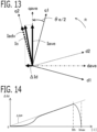
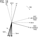
- the magnetic pole position for control ⁇ c coincides with the magnetic pole position ⁇ 2 of the most advance phase, and the direction of the current vector coincides with the direction of the q2-axis.
- the magnetic pole position for control ⁇ c coincides with a magnetic pole position ⁇ ave of a middle phase between the magnetic pole position ⁇ 2 of the most advanced phase and the magnetic pole position ⁇ 1 of the most delayed phase, and the direction of the current vector coincides with a middle phase direction between the q2-axis and the q1-axis.
- the phase advance ⁇ that the sixth-order torque ripple component becomes the smallest is the skew angle ⁇ e/2.
- the magnetic pole position for control ⁇ c becomes the middle phase between the magnetic pole position ⁇ 2 of the most advanced phase and the magnetic pole position ⁇ 1 of the most delayed phase. This is because, at the middle phase, the sixth-order torque ripple component caused by the magnetic pole of the second skew step 112b, and the sixth-order torque ripple component caused by the magnetic pole of the first skew step 112a are canceled with each other.
- FIG. 9 shows characteristics of an interlinkage flux ⁇ d2 of the d2-axis with respect to the d2-axis current Id2.
- the d2-axis current Id2 is increased from 0, although the interlinkage flux ⁇ d2 of the d2-axis increases, the inclination decreases. This is because the magnetic saturation occurs in the teeth part of the stator which opposes to the magnetic pole of the second skew step 112b, and the d-axis inductance Ld decreases. If this magnetic saturation occurs, the sixth-order torque ripple component increases. Even if the absolute value
- the current control unit 33 brings a controlling current vector Ic close to the current vector of most advanced phase Iadv from the current vector of middle phase Iave, as the winding currents which flow into the three-phase windings increases.
- the dq-axis rotating coordinate system of most advanced phase is a dq-axis rotating coordinate system which consists of the d2-axis defined in the magnetic pole position ⁇ 2 direction of the second skew step 112b whose phase is most advanced in the rotation direction R, and the q2-axis defined in the direction advanced to the d2-axis by 90 degrees in the electrical angle.
- the dq-axis rotating coordinate system of middle phase is a dq-axis rotating coordinate system which consists of a d-axis (hereinafter, referred to as dave-axis) defined in the direction of the middle phase between the magnetic pole position ⁇ 2 of the second skew step 112b whose phase is most advanced and the magnetic pole position ⁇ 1 of the first skew step 112a whose phase is most delayed in the rotation direction R, and a q-axis (hereinafter, referred to as qave-axis) defined in the direction advanced to the dave-axis by 90 degrees in the electrical angle.
- dave-axis d-axis
- qave-axis q-axis
- the controlling current vector Ic is brought close to the current vector of most advanced phase Iadv from the current vector of middle phase Iave as the winding currents (absolute value of current vector) increase, when the winding currents are small, the torque ripple component generated by the magnetic pole of the most advanced phase and the torque ripple component generated by the magnetic pole of the most delayed phase are canceled with each other, and the sixth-order torque ripple component can be reduced. And, even when the winding currents increase, the d2-axis current Id2 of the most advanced phase can be suppressed from increasing until the magnetic saturation occurs, and the sixth-order torque ripple component can be reduced. Accordingly, the phase of the current vector with respect to the magnetic pole position which is shifted in the circumferential direction is changed appropriately according to increase and decrease in the winding currents, and the sixth-order torque ripple component can be reduced effectively.
- the current control unit 33 brings the controlling current vector Ic close to the current vector of most advanced phase Iadv from the current vector of middle phase Iave, as the winding currents which flow into the three-phase windings increase.
- the current vector of most advanced phase Iadv becomes a current vector in the q2-axis direction of the dq-axis rotating coordinate system of most advanced phase
- the current vector of middle phase Iave becomes a current vector of the gave-axis direction of the dq-axis rotating coordinate system of middle phase.
- the controlling current vector can be brought close to the current vector in the q2-axis direction of the dq-axis rotating coordinate system of most advanced phase from the current vector of the gave-axis direction of the dq-axis rotating coordinate system of middle phase.
- the increase in the d2-axis current Id2 which expressed currents on the dq-axis rotating coordinate system of most advanced phase can be suppressed, and the increase in the sixth-order torque ripple component in the electrical angle can be suppressed.
- the magnetic pole position setting unit 331 brings the magnetic pole position for control ⁇ c close to the magnetic pole position ⁇ 2 whose phase is most advanced in the rotation direction R, from the magnetic pole position ⁇ ave of the middle phase between the magnetic pole position ⁇ 2 of the second skew step 112b whose phase is most advanced in the rotation direction R and the magnetic pole position ⁇ 1 of the first skew step 112a whose phase is most delayed.
- the current command value calculation unit 332 calculates the current command values for control on the dq-axis rotating coordinate system for control which is set on the basis of the magnetic pole position for control ⁇ c.
- the voltage command value calculation unit 333 calculates the voltage command values based on the detection values of currents and the current command values for control, on the dq-axis rotating coordinate system for control which is set on the basis of the magnetic pole position for control ⁇ c.
- the current vector Ic of the current command values for control and the controlling current vector Ic can be brought close to the current vector of most advanced phase Iadv calculated on the dq-axis rotating coordinate system of most advanced phase, from the current vector of middle phase Iave calculated on the dq-axis rotating coordinate system of middle phase.
- the magnetic pole position setting unit 331 brings the magnetic pole position for control ⁇ c close to the magnetic pole position ⁇ 2 of the most advanced phase, from the magnetic pole position ⁇ ave of the middle phase between the magnetic pole position ⁇ 2 of the most advanced phase and the magnetic pole position ⁇ 1 of the most delayed phase.
- the magnetic pole position setting unit 331 calculates the correction amount of magnetic pole position ⁇ corresponding to the present winding current
- the correction amount of magnetic pole position ⁇ is set to approach the skew angle ⁇ e/2 from 0 as the winding current
- the magnetic pole position setting unit 331 calculates, as the winding current
- , an absolute value of current vector, based on the current command value of d-axis Ido and the current command value of q-axis Iqo for control, as shown in the next equation. Since Ido is 0 by Id 0 control, the winding current
- the voltage command value calculation unit 333 calculates voltage command values based on the detection values of currents, the current command values for control, and the magnetic pole position for control ⁇ c. In the present embodiment, the voltage command value calculation unit 333 calculates the voltage command values based on the detection values of currents and the current command values for control, on the dq-axis rotating coordinate system for control which is set on the basis of the magnetic pole position for control ⁇ c. As shown in FIG. 1 , the voltage command value calculation unit 333 is provided with a current coordinate conversion unit 3331, a dq-axis voltage command value calculation unit 3332, and a voltage coordinate conversion unit 3333.
- the current coordinate conversion unit 3331 converts the current detection values Iur, Ivr, Iwr of the three-phase windings detected by the current detection unit 32 into the current detection value of d-axis Idr and the current detection value of q-axis Iqr on the dq-axis rotating coordinate system for the control which is set on the basis of the magnetic pole position for control ⁇ c.
- the d-axis is defined in the direction of the magnetic pole position for control ⁇ c
- the q-axis is defined in the direction advanced to the d-axis by 90 degrees in the electrical angle.
- the current coordinate conversion unit 3331 converts the current detection values of three-phase Iur, Ivr, Iwr into the current detection value of d-axis Idr and the current detection value of q-axis Iqr, by performing the three-phase/two-phase conversion and the rotating coordinate conversion based on the magnetic pole position for control ⁇ c.
- Idr Iqr 2 3 cos ⁇ c cos ⁇ c ⁇ 2 3 ⁇ cos ⁇ c + 2 3 ⁇ ⁇ sin ⁇ c ⁇ sin ⁇ c ⁇ 2 3 ⁇ ⁇ sin ⁇ c + 2 3 ⁇ Iur Ivr Iwr
- the dq-axis voltage command value calculation unit 3332 performs a current feedback control that changes a voltage command value of d-axis Vdo and a voltage command value of q-axis Vqo by PI control and the like, so that the current detection value of d-axis Idr approaches the current command value of d-axis Ido for control, and the current detection value of q-axis Iqr approaches the current command value of q-axis Iqo for control.
- a feedforward control for non-interfering between the d-axis current and the q-axis current and the like may be performed.
- the voltage coordinate conversion unit 3333 converts the voltage command values of dq-axis Vdo, Vqo on the dq-axis rotating coordinate system for control into the voltage command values of three-phase Vuo, Vvo, Vwo, by performing the fixed coordinate conversion and the two-phase/three-phase conversion based on the magnetic pole position for control ⁇ c.
- Various kinds of modulation such as the third order harmonic wave injection modulation, may be added to the voltage command values of three-phase.
- Vuo Vvo Vwo 2 3 cos ⁇ c ⁇ sin ⁇ c cos ⁇ c ⁇ 2 3 ⁇ ⁇ sin ⁇ c ⁇ 2 3 ⁇ cos ⁇ c + 2 3 ⁇ ⁇ sin ⁇ c + 2 3 ⁇ Vdo Vqo
- the switching control unit 34 controls on/off the plurality of switching devices based on the voltage command values.
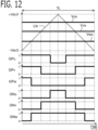
- the switching control unit 34 controls on/off switching devices by comparing each of the voltage command values of three-phase Vuo, Vvo, Vwo and a carrier wave CA which vibrates at the carrier period Tc.
- the carrier wave CA is a triangular wave which vibrates centering on 0 at a carrier period Tc with an amplitude of half value Vdc/2 of the power source voltage.
- the power source voltage Vdc may be detected by a voltage sensor.
- the switching control unit 34 turns on the switching signal GP of the positive electrode side switching device (in this example, 1) and turns on the positive electrode side switching device when carrier wave CA is less than the voltage command value, and turns off the switching signal GP of the positive electrode side switching device (in this example, 0) and turns off the positive electrode side switching device when the carrier wave CA exceeds the voltage command value.
- the switching control unit 34 turns off the switching signal GN of the negative electrode side switching device (in this example, 0) and turns off the negative electrode side switching device when the carrier wave CA is less than the voltage command value, and turns on the switching signal GN of the negative electrode side switching device (in this example, 1) and turns on the negative electrode side switching device when the carrier wave CA exceeds the voltage command value.
- a short circuit prevention period (dead time) which turns off both of the positive electrode side and the negative electrode side switching device may be provided.
- Embodiment 2 The rotary electric machine apparatus according to Embodiment 2 will be explained. The explanation for constituent parts the same as those in Embodiment 1 will be omitted.
- the basic configuration of the rotary electric machine 1, the inverter 4, and the controller 6 according to the present embodiment is the same as that of Embodiment 1.
- Embodiment 2 is different from Embodiment 1 in processing of the controller 6.
- the current control unit 33 brings the current vector Ic of the current command values for control close to the current vector of most advanced phase Iadv from the current vector of middle phase Iave.
- the magnetic pole position setting unit 331 detects, as the magnetic pole position for control ⁇ c, the magnetic pole position ⁇ ave of the middle phase between the magnetic pole position ⁇ 2 of the second skew step 112b whose phase is most advanced and the magnetic pole position ⁇ 1 of the first skew step 112a whose phase is most delayed in the rotation direction R.
- the current command value calculation unit 332 calculates the current command values on the dq-axis rotating coordinate system of middle phase which is set on the basis of the magnetic pole position ⁇ ave of the middle phase; and calculates the current command values for control by decreasing the d-axis component of the current command values by the d-axis current decrease amount ⁇ Id. As the winding currents increase, the current command value calculation unit 332 increases the d-axis current decrease amount ⁇ Id so that the current vector Ic of the current command values for control approaches the current vector of most advanced phase Iadv from the current vector of middle phase Iave.
- the voltage command value calculation unit 333 calculates the voltage command values based on the detection values of currents and the current command values for control, on the dq-axis rotating coordinate system of middle phase which is set on the basis of the magnetic pole position ⁇ ave of the middle phase.
- the current vector Ic of the current command values for control can be brought close to the current vector of most advanced phase Iadv from the current vector of middle phase Iave.
- the increase in the d2-axis current Id2 which expressed currents on the dq-axis rotating coordinate system of most advanced phase can be suppressed, and the increase in the sixth-order torque ripple component in the electrical angle can be suppressed.
- the current command value calculation unit 332 calculates the current command value of d-axis Ido for control by decreasing the current command value of d-axis Idave of the middle phase by the d-axis current decrease amount ⁇ Id.
- the current command value calculation unit 332 sets the current command value of q-axis Iqave of the middle phase as the current command value of q-axis Iqo for control as it is.
- Ido Idave ⁇ ⁇ Id
- Iqo Iqave
- the current command value calculation unit 332 calculates the d-axis current decrease amount ⁇ Id corresponding to the present winding current
- ⁇ Id * tan ⁇ e / 2 ⁇ Iqave
- the current vector Ic of the current command values for control can be brought close to the current vector of most advanced phase Iadv which coincides with the q2-axis.
- the current command value calculation unit 332 calculates, as the winding current
- , an absolute value of current vector based on the current command value of d-axis Idave and the current command value of q-axis Iqave of the middle phase, as shown in the next equation. Since Idave is 0 by Id 0 control, the winding current
- is proportional to the current command value of q-axis Iqave. Instead of the current command value of d-axis Idave and the current command value of q-axis Iqave of the middle phase, the current detection value of d-axis Idr and the current detection value of q-axis Iqr may be used. I ⁇ Idave 2 + Iqave 2
- the torque of the rotary electric machine becomes an average of a torque by the magnetic pole of the most advanced phase, and a torque by the magnetic pole of the most delayed phase, it changes in proportion to the q-axis current of the middle phase. That is to say, the torque of the rotary electric machine becomes large, as the q-axis current of the middle phase becomes large.
- a current limit circle is shown in FIG. 15 , the current which can be supplied to the windings has an upper limit.
- the absolute value of the current vector increases.
- the current command value calculation unit 332 brings the current vector Ic of the current command values for control close to the current vector of middle phase Iave from the current vector of most advanced phase Iadv, as the winding current
- Ith which is set to a value smaller than the upper limit current value Imax
- the current command value calculation unit 332 decreases the d-axis current decrease amount ⁇ Id to 0, as the winding current
- the current vector Ic of the current command values for control can be brought close to the current vector of middle phase Iave from the current vector of most advanced phase Iadv, and the maximum torque can be increased while sacrificing the reduction of the sixth-order torque ripple component.
- the rotary electric machine apparatus will be explained.
- the explanation for constituent parts the same as those in each of Embodiments 1 or 2 will be omitted.
- the basic configuration of the rotary electric machine 1, the inverter 4, and the controller 6 according to the present embodiment is the same as that of Embodiment 1 or 2.
- the rotary electric machine 1 is rotatable to one side and the other side, and accordingly, processing of the controller 6 is different from Embodiment 1 or 2.
- the rotary electric machine 1 rotates only to one side. However, depending on application, the rotary electric machine may be rotatable to one side and the other side. Then, the current control unit 33 sets the magnetic pole position whose phase is most advanced and the magnetic pole position whose phase is most delayed in the rotation direction, according to the rotation direction of one side or the other side.
- the same rotation direction as the rotation direction R of Embodiment 1 is set to a rotation direction R1 of one side, and a rotation direction opposite to the rotation direction R of Embodiment 1 is sets to a rotation direction R2 of the other side.
- the dq-axis rotating coordinate system of most advanced phase is a dq-axis rotating coordinate system which consists of the d2-axis defined in the direction of the magnetic pole position ⁇ 2 of the second skew step 112b whose phase is most advanced in the rotation direction R1 of one side, and the q2-axis defined in the direction advanced to the d2-axis by 90 degrees in the electrical angle in the rotation direction R1 of one side.
- the dq-axis rotating coordinate system of middle phase is a dq-axis rotating coordinate system which consists of the dave-axis defined in the direction of the middle phase between the magnetic pole position ⁇ 2 of the second skew step 112b whose phase is most advanced and the magnetic pole position ⁇ 1 of the first skew step 112a whose phase is most delayed in the rotation direction R1 of one side, and the gave-axis defined in the direction advanced to the dave-axis by 90 degrees in the electrical angle in the rotation direction R1 of one side.
- the dq-axis rotating coordinate system of most advanced phase is a dq-axis rotating coordinate system which consists of the d1-axis defined in the direction of the magnetic pole position ⁇ 1 of the first skew step 112a whose phase is most advanced in the rotation direction R2 of the other side, and the q1-axis defined in the direction advanced to the d1-axis by 90 degrees in the electrical angle in the rotation direction R2 of the other side.
- the dq-axis rotating coordinate system of middle phase is a dq-axis rotating coordinate system which consists of the dave-axis defined in the direction of the middle phase between the magnetic pole position ⁇ 1 of the first skew step 112a whose phase is most advanced and the magnetic pole position ⁇ 2 of the second skew step 112b whose phase is most delayed in the rotation direction R2 of the other side, and the gave-axis defined in the direction advanced to the dave-axis by 90 degrees in the electrical angle in the rotation direction R2 of the other side.
- the current control unit 33 brings the controlling current vector close to the current vector of most advanced phase Iadv from the current vector of middle phase Iave, as the winding currents which flow into the three-phase windings increase.
- Embodiment 1 The case where a method similar to Embodiment 1 is used is explained.
- the rotation direction is the rotation direction R1 of one side
- the magnetic pole position setting unit 331 brings the magnetic pole position for control ⁇ c close to the magnetic pole position ⁇ 2 of the second skew step 112b whose phase is most advanced in the rotation direction R1 of one side from the magnetic pole position ⁇ ave of the middle phase.
- the current command value calculation unit 332 calculates the current command values for control on the dq-axis rotating coordinate system for control which is set on the basis of the magnetic pole position for control ⁇ c.
- the voltage command value calculation unit 333 calculates the voltage command values based on the detection values of currents and the current command values for control, on the dq-axis rotating coordinate system for control which is set on the basis of the magnetic pole position for control ⁇ c.
- the dq-axis rotating coordinate system for the control in this case consists of the dc-axis defined in the direction of the magnetic pole position for control ⁇ c, and the qc-axis defined in the direction advanced to the dc-axis by 90 degrees in the electrical angle in the rotation direction R1 of one side.
- the magnetic pole position setting unit 331 brings the magnetic pole position for control ⁇ c close to the magnetic pole position ⁇ 1 of the first skew step 112a whose phase is most advanced in the rotation direction R2 of the other side from the magnetic pole position ⁇ ave of the middle phase.
- the current command value calculation unit 332 calculates the current command values for control on the dq-axis rotating coordinate system for control which is set on the basis of the magnetic pole position for control ⁇ c. Also in this case, similarly to the case of the rotation direction R1 of one side, the current command value of q-axis Iqo becomes a positive value.
- the voltage command value calculation unit 333 calculates the voltage command values based on the detection values of currents and the current command values for control, on the dq-axis rotating coordinate system for control which is set on the basis of the magnetic pole position for control ⁇ c.
- the dq-axis rotating coordinate system for the control in this case consists of the dc-axis defined in the direction of the magnetic pole position for control ⁇ c, and the qc-axis defined in the direction advanced to the dc-axis by 90 degrees in the electrical angle in the rotation direction R2 of the other side.
- the magnetic pole position setting unit 331 detects the magnetic pole position ⁇ ave of the middle phase as the magnetic pole position for control ⁇ c.
- the current command value calculation unit 332 calculates the current command values on the dq-axis rotating coordinate system of middle phase which is set on the basis of the magnetic pole position ⁇ ave of the middle phase; and calculates the current command values for control by decreasing the d-axis component of the current command values by the d-axis current decrease amount ⁇ Id.
- the current command value calculation unit 332 increases the d-axis current decrease amount ⁇ Id so that the current vector Ic of the current command values for control approaches the current vector of most advanced phase Iadv from the current vector of middle phase Iave. Then, the voltage command value calculation unit 333 calculates the voltage command values based on the detection values of currents and the current command values for control, on the dq-axis rotating coordinate system of middle phase which is set on the basis of the magnetic pole position ⁇ ave of the middle phase.
- the dq-axis rotating coordinate system of middle phase in this case consists of the dave-axis defined in the direction of the magnetic pole position ⁇ ave of the middle phase, and the gave-axis defined in the direction advanced to the dave-axis by 90 degrees in the electrical angle in the rotation direction R1 of one side.
- the magnetic pole position setting unit 331 detects the magnetic pole position ⁇ ave of the middle phase as the magnetic pole position for control ⁇ c.
- the current command value calculation unit 332 calculates the current command values on the dq-axis rotating coordinate system of middle phase which is set on the basis of the magnetic pole position ⁇ ave of the middle phase; and calculates the current command values for control by decreasing the d-axis component of the current command values by the d-axis current decrease amount ⁇ Id.
- the current command value calculation unit 332 increases the d-axis current decrease amount ⁇ Id so that the current vector Ic of the current command values for control approaches the current vector of most advanced phase Iadv from the current vector of middle phase Iave. Also in this case, similarly to the case of the rotation direction R1 of one side, the current command value of q-axis Iqo becomes a positive value, and the current command value of d-axis Ido becomes a negative value.
- the voltage command value calculation unit 333 calculates the voltage command values based on the detection values of currents and the current command values for control, on the dq-axis rotating coordinate system of middle phase which is set on the basis of the magnetic pole position ⁇ ave of the middle phase.
- the dq-axis rotating coordinate system of middle phase in this case consists of the dave-axis defined in the direction of the magnetic pole position ⁇ ave of the middle phase, and the qave-axis defined in the direction advanced to the dave-axis by 90 degrees in the electrical angle in the rotation direction R2 of the other side.
- the dq-axis rotating coordinate system of most advanced phase may be set to a dq-axis rotating coordinate system which consists of the d1-axis defined in the direction of the magnetic pole position ⁇ 1 of the first skew step 112a whose phase is most advanced in the rotation direction R2 of the other side, and the q1-axis defined in the direction advanced to the d1-axis by 90 degrees in the electrical angle in the rotation direction R1 of one side.
- the dq-axis rotating coordinate system of middle phase may be set to a dq-axis rotating coordinate system which consists of the dave-axis defined in the direction of the middle phase between the magnetic pole position ⁇ 1 of the first skew step 112a whose phase is most advanced and the magnetic pole position ⁇ 2 of the second skew step 112b whose phase is most delayed in the rotation direction R2 of the other side, and the gave-axis defined in the direction advanced to the dave-axis by 90 degrees in the electrical angle in the rotation direction R1 of one side.
- the current command value of q-axis Iqo becomes a negative value that the positive or negative sign is reversed. Also in this case, it becomes equivalent to an above-mentioned configuration substantially.
- This kind rotary electric machine is used for a driving force source of an electric power steering apparatus as shown in FIG. 19 , for example.
- the electric power steering device is provided with a handle 63 that a driver rotates right and left, a shaft 64 that is connected with the handle 63 and transmits a steering wheel torque by the handle 63 to a steering mechanism of wheels 62, a torque sensor 65 that is mounted on the shaft 64 and detects the steering wheel torque by the handle 63, and a driving force transmission mechanisms 61, such as a worm gear mechanism, which transmits a driving force of the rotary electric machine 1 to the shaft 64.
- the controller 6 makes the rotary electric machine 1 output a torque according to a steering torque of the handle 63 detected by the torque sensor 65. Accordingly, the torque command value Tref is set according to the steering torque detected by the torque sensor 65.
- the controller 6 makes the rotary electric machine 1 output a torque of the rotation direction R1 of one side according to the steering torque.
- the driver rotates the handle 63 to right side the rotary electric machine 1 rotates in the rotation direction R1 of one side, for example, and the controller 6 makes the rotary electric machine 1 output a torque of the rotation direction R1 of one side according to the steering torque.
- the driver rotates the handle 63 to left side the rotary electric machine 1 rotates in the rotation direction R2 of the other side, for example, and the controller 6 makes the rotary electric machine 1 output a torque of the rotation direction R2 of the other side according to the steering torque.
- Embodiment 4 The rotary electric machine apparatus according to Embodiment 4 will be explained. The explanation for constituent parts the same as those in each of Embodiments 1 or 2 will be omitted.
- the basic configuration of the rotary electric machine 1, the inverter 4, and the controller 6 according to the present embodiment is the same as that of Embodiment 1 or 2.
- the permanent magnet is embedded inside the rotor, and the calculation method of the current command values is different from Embodiment 1 or 2.
- the permanent magnets 161 are embedded inside the rotor 11, and it is an embedded magnet type synchronous motor.
- the rotor 11 is provided with a rotor core 162 and the permanent magnets 161 are embedded inside the rotor core 162.
- the permanent magnets 161 have the skew structure in which the magnetic pole positions are shifted in the circumferential direction in two steps in the axial direction X.
- a first skew step 162a is provided in the axial direction one side X1 of the rotor 11, and a second skew step 162b is provided in the axial direction the other side X2.
- eight magnetic poles 161 are disposed at equal intervals in the circumferential direction.
- the N pole and the S pole are disposed alternately in the circumferential direction.
- the magnetic poles 161 (for example, N poles) of the second skew step 162b and the magnetic poles 161 (for example, N poles) of the first skew step 162a are shifted in the circumferential direction with each other.
- the magnetic poles 161 of the second skew step 162b are shifted by 30 degrees in the rotation direction R in the electrical angle with respect to the magnetic poles 161 of the first skew step 162a, and the skew angle ⁇ e is 30 degrees in the electrical angle.
- the magnetic pole position ⁇ 2 of the second skew step 162b is advanced to the magnetic pole position ⁇ 1 of the first skew step 162a by the skew angle ⁇ e (in this example, 30 degrees) in the rotation direction R in the electrical angle.
- ⁇ e in this example, 30 degrees
- the dq-axis rotating coordinate system of most advanced phase which is set on the basis of the magnetic pole position ⁇ 2 of the second skew step 162b whose phase is most advanced in the rotation direction R, consists of the d2-axis defined in the magnetic pole position ⁇ 2 direction of the second skew step 162b, and the q2-axis defined in the direction advanced to the d2-axis by 90 degrees in the electrical angle.
- the dq-axis rotating coordinate system of most delayed phase which is set on the basis of the magnetic pole position ⁇ 1 of the first skew step 162a whose phase is most delayed in the rotation direction R, consists of the d1-axis defined in the magnetic pole position ⁇ 1 direction of the first skew step 162a, and the q1-axis defined in the direction advanced to the d1-axis by 90 degrees in the electrical angle.
- the q-axis inductance Lq becomes larger than the d-axis inductance Ld, and generally the current command values are set by the maximum torque/current control.
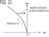
- the maximum torque/current control as shown in FIG. 21 , the current command values of d-axis and q-axis Ido, Iqo which maximize the generated torque to the same current is calculated.
- the torque command value Tref increases, along the maximum torque/current curve, the current command value of q-axis Iqo is increased from 0, and the current command value of d-axis Ido is decreased from 0.
- the phase advance ⁇ of the magnetic pole position for control ⁇ c with respect to the magnetic pole position ⁇ 1 of the most delayed phase may be brought close to the skew angle ⁇ e corresponding to the magnetic pole position ⁇ 2 of the most advanced phase, from the skew angle ⁇ e/2 corresponding to the middle phase between the magnetic pole position ⁇ 1 of the most delayed phase and the magnetic pole position ⁇ 2 of the most advanced phase.
- the current control unit 33 brings the controlling current vector Ic close to the current vector of most advanced phase Iadv from the current vector of middle phase Iave, as the winding currents which flow into the three-phase windings increase.
- the magnetic pole position setting unit 331 brings the magnetic pole position for control ⁇ c close to the magnetic pole position ⁇ 2 whose phase is most advanced in the rotation direction, from the magnetic pole position ⁇ ave of the middle phase between the magnetic pole position ⁇ 2 of the second skew step 112b whose phase is most advanced in the rotation direction and the magnetic pole position ⁇ 1 of the first skew step 112a whose phase is most delayed.
- the current command value calculation unit 332 calculates the current command values for control by the maximum torque/current control, on the dq-axis rotating coordinate system for control which is set on the basis of the magnetic pole position for control ⁇ c.
- the voltage command value calculation unit 333 calculates the voltage command values based on the detection values of currents and the current command values for control, on the dq-axis rotating coordinate system for control which is set on the basis of the magnetic pole position for control ⁇ c.
- the current command value calculation unit 332 calculates the current command values of d-axis and q-axis Ido, Iqo for control by the maximum torque/current control, on the dq-axis rotating coordinate system for control. For example, by referring to a current command value setting data in which a relationship between the torque command value Tref and the current command values of d-axis and q-axis Ido, Iqo is preliminarily set as shown in FIG. 21 , the current command value calculation unit 332 calculates the current command values of d-axis and q-axis Ido, Iqo for control corresponding to the present torque command value Tref. Since other points are the same as Embodiment 1, explanation is omitted.
- the magnetic pole position setting unit 331 sets, as the magnetic pole position for control ⁇ c, the magnetic pole position ⁇ ave of the middle phase between the magnetic pole position ⁇ 2 of the second skew step 112b whose phase is most advanced and the magnetic pole position ⁇ 1 of the first skew step 112a whose phase is most delayed in the rotation direction.
- the current command value calculation unit 332 calculates the current command values by the maximum torque/current control, on the dq-axis rotating coordinate system of middle phase which is set on the basis of the magnetic pole position ⁇ ave of the middle phase; and calculates the current command values for control by decreasing the d-axis component of the current command values by the d-axis current decrease amount ⁇ Id.
- the current command value calculation unit 332 increases the d-axis current decrease amount ⁇ Id so that the current vector Ic of the current command values for control approaches the current vector of most advanced phase Iadv from the current vector of middle phase Iave. Then, the voltage command value calculation unit 333 calculates the voltage command values based on the detection values of currents and the current command values for control, on the dq-axis rotating coordinate system of middle phase which is set on the basis of the magnetic pole position ⁇ ave of the middle phase.
- the current command value calculation unit 332 calculates the current command values of d-axis and q-axis Idave, Iqave of the middle phase by the maximum torque/current control, on the dq-axis rotating coordinate system of middle phase. For example, by referring to the current command value setting data in which a relationship between the torque command value Tref and the current command values of d-axis and q-axis Ido, Iqo is preliminarily set as shown in FIG. 21 , the current command value calculation unit 332 calculates the current command values of d-axis and q-axis Idave, Iqave of the middle phase corresponding to the present torque command value Tref.
- the current command value calculation unit 332 calculates the current command value of d-axis Ido for control by decreasing the current command value of d-axis Idave of the middle phase by the d-axis current decrease amount ⁇ Id.
- the current command value calculation unit 332 sets the current command value of q-axis Iqave of the middle phase as the current command value of q-axis Iqo for control as it is.
- the current command value calculation unit 332 calculates the d-axis current decrease amount ⁇ Id corresponding to the present winding current
- the d-axis current decrease amount ⁇ Id is increased so that the current vector Ic of the current command values for control approaches the current vector of most advanced phase Iadv from the current vector of middle phase Iave the as winding current
- the current command value calculation unit 332 brings the current vector Ic of the current command values for control close to the current vector of middle phase Iave from the current vector of most advanced phase Iadv, as the winding current
- the current command value calculation unit 332 decreases the d-axis current decrease amount ⁇ Id to 0, as the winding current
- Embodiment 5 The rotary electric machine apparatus according to Embodiment 5 will be explained. The explanation for constituent parts the same as those in each of Embodiments 1, 2, or 4 will be omitted.
- the basic configuration of the rotary electric machine 1, the inverter 4, and the controller 6 according to the present embodiment is the same as that of Embodiment 1, 2, or 4.
- the execution region of the magnetic flux weakening control is set to a region where the induced voltage of the windings becomes close to the upper limit voltage corresponding to the power source voltage Vdc. If the current command value of d-axis is increased in the negative direction and the magnetic flux of the permanent magnet is weakened, the induced voltage of the winding can be weakened and the torque of the rotary electric machine can be increased.
- the current control unit 33 determines the execution region of control corresponding to the present rotational angle speed ⁇ and the present torque command value Tref.
- the current control unit 33 brings the controlling current vector Ic close to the current vector of most advanced phase Iadv from the current vector of middle phase Iave, as the winding currents which flow into the three-phase windings increase.
- the current control unit 33 brings the controlling current vector Ic close to the current vector of most advanced phase Iadv from the current vector of middle phase Iave, as the winding currents which flow into the three-phase windings increase.
- the magnetic pole position setting unit 331 brings the magnetic pole position for control ⁇ c close to the magnetic pole position ⁇ 2 of the most advanced phase in the rotation direction, from the magnetic pole position ⁇ ave of the middle phase. Then, the current command value calculation unit 332 calculates the current command values for control by the magnetic flux weakening control, on the dq-axis rotating coordinate system for control which is set on the basis of the magnetic pole position for control ⁇ c.
- the voltage command value calculation unit 333 calculates the voltage command values based on the detection values of currents and the current command values for control, on the dq-axis rotating coordinate system for control which is set on the basis of the magnetic pole position for control ⁇ c.
- the current command value calculation unit 332 calculates the current command values of d-axis and q-axis Ido, Iqo for control by the magnetic flux weakening control, on the dq-axis rotating coordinate system for control. For example, the current command value calculation unit 332 calculates an effective value Vamp of interphase voltages applied to the windings, and increases and decreases the current command value of d-axis Ido so that the effective value Vamp of interphase voltages approach a target effective value Vampo.
- the current command value calculation unit 332 calculates the effective value Vamp of interphase voltages, based on the voltage command values of dq-axis Vdo, Vqo of the last time calculation period using the next equation.
- the current command value calculation unit 332 sets the target effective value Vampo based on the power source voltage Vdc.
- Vamp ⁇ Vdo 2 + Vqo 2
- Vampo Vdc / ⁇ 2
- the current command value calculation unit 332 calculates a deviation ⁇ Vamp between the effective value Vamp of interphase voltages and the target effective value Vampo, and calculates the current command value of d-axis Ido for control by integrating the deviation ⁇ Vamp.
- Ki is an integral gain.
- Iqo Kt ⁇ Tref
- the current command value of d-axis is increased in the negative direction by the magnetic flux weakening control, from the current command values of d-axis and q-axis calculated by the maximum torque/current control, the current command value of q-axis Iqo for control is also changed so that the same torque can be maintained.
- the current command value of d-axis Ido for control is upper-limited by the current command value of d-axis in the case of the maximum torque/current control.
- the magnetic pole position setting unit 331 sets the magnetic pole position ⁇ ave of the middle phase as the magnetic pole position for control ⁇ c.
- the current command value calculation unit 332 calculates the current command values by the magnetic flux weakening control, on the dq-axis rotating coordinate system of middle phase which is set on the basis of the magnetic pole position ⁇ ave of the middle phase; and calculates the current command values for control by decreasing the d-axis component of the current command values by the d-axis current decrease amount ⁇ Id.
- the current command value calculation unit 332 increases the d-axis current decrease amount ⁇ Id so that the current vector Ic of the current command values for control approaches the current vector of most advanced phase Iadv calculated by the magnetic flux weakening control, from the current vector of middle phase Iave calculated by the magnetic flux weakening control. Then, the voltage command value calculation unit 333 calculates the voltage command values based on the detection values of currents and the current command values for control, on the dq-axis rotating coordinate system of middle phase which is set on the basis of the magnetic pole position ⁇ ave of the middle phase.
- the current command value calculation unit 332 calculates the effective value Vamp of interphase voltages, and the target effective value Vampo, similarly to the above equation (11).
- the current command value calculation unit 332 calculates a deviation ⁇ Vamp between the effective value Vamp of interphase voltages and the target effective value Vampo, and calculates the current command value of d-axis Idave of the middle phase by integrating the deviation ⁇ Vamp.
- the current command value of d-axis is increased in the negative direction by the magnetic flux weakening control, from the current command values of d-axis and q-axis calculated by the maximum torque/current control, the current command value of q-axis Iqave of the middle phase is also changed so that the same torque can be maintained.
- the current command value of d-axis Idave of the middle phase is upper-limited by the current command value of d-axis in the case of the maximum torque/current control.
- the current command value calculation unit 332 calculates the current command value of d-axis Ido for control by decreasing the current command value of d-axis Idave of the middle phase by the d-axis current decrease amount ⁇ Id.
- the current command value calculation unit 332 sets the current command value of q-axis Iqave of the middle phase as the current command value of q-axis Iqo for control as it is.
- the d-axis current decrease amount ⁇ Id is set similarly to Embodiment 1.
- Ido Idave ⁇ ⁇ Id
- Iqo Iqave
- the current command value calculation unit 332 calculates the component of the qave-axis which expressed the winding current III on the dq-axis rotating coordinate system of middle phase, as the winding current
- I ⁇ Ido 2 + Iqo 2 ⁇ sin ⁇
- the permanent magnets have the skew structure in which the magnetic pole positions are shifted in the circumferential direction in two steps in the axial direction X.
- the permanent magnet may have a skew structure in which the magnetic pole positions are shifted in the circumferential direction in three or more steps in the axial direction X or continuously in the axial direction X.
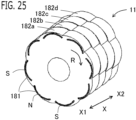
- the permanent magnets may have the skew structure in which the magnetic pole positions are shifted in the circumferential direction in four steps in the axial direction X. From the axial direction one side X1 to the axial direction the other side X2, in order, the first skew step 182a, the second skew step 182b, the third skew step 182c, and the fourth skew step 182d are provided, and each magnetic pole position is shifted in the rotation direction R by 15 degrees in the electrical angle. In the peripheral part of each skew step, eight magnetic poles 181 (four N poles and four S poles) are disposed at equal intervals in the circumferential direction, and are embedded inside of the rotor 11.
- the magnetic pole (N pole) of the fourth skew step 182d whose phase is most advanced in the rotation direction R is shifted to the magnetic pole (N pole) of the first skew step 182a whose phase is most delayed in the rotation direction R, by the skew angle ⁇ e (in this example, 60 degrees) in the electrical angle.
- the dq-axis rotating coordinate system of most advanced phase is set to the d-axis defined in the magnetic pole position direction of the fourth skew step 182d whose phase is most advanced in the rotation direction R, and the q-axis defined in the direction advanced to the d-axis by 90 degrees in the electrical angle.
- the dq-axis rotating coordinate system of middle phase is set to the d-axis defined in the direction of the middle phase between the magnetic pole position of the fourth skew step 182d whose phase is most advanced and the magnetic pole position of the first skew step 182a whose phase is most delayed in the rotation direction R, and the q-axis defined in the direction advanced to the d-axis by 90 degrees in the electrical angle.
- the permanent magnets may have the skew structure in which the magnetic pole positions are shifted in the circumferential direction continuously in the axial direction X.
- eight magnetic poles 191 are disposed at equal intervals in the circumferential direction, and are stuck on the surface of the rotor. From the axial direction one side X1 to the axial direction the other side X2, each magnetic pole 191 is continuously shifted in the rotation direction R.
- FIG. 27 shows an expansion plan
- the magnetic pole (N pole) of the end in the axial direction one side X1 whose phase is most advanced in the rotation direction R is shifted to the magnetic pole (N pole) of the end in the axial direction the other side X2 whose phase is most delayed in the rotation direction R, by the skew angle ⁇ e (in this example, 60 degrees) in the electrical angle.
- the dq-axis rotating coordinate system of most advanced phase is set to the d-axis defined in the magnetic pole position direction of the end in the axial direction one side X1 whose phase is most advanced in the rotation direction R, and the q-axis defined in the direction advanced to the d-axis by 90 degrees in the electrical angle.
- the dq-axis rotating coordinate system of middle phase is set to the d-axis defined in the direction of the middle phase between the magnetic pole position of the end in the axial direction one side X1 whose phase is most advanced and the magnetic pole position of the end in the axial direction the other side X2 whose phase is most delayed in the rotation direction R, and the q-axis defined in the direction advanced to the d-axis by 90 degrees in the electrical angle.
- the skew structure in which the magnetic pole positions are shifted in the circumferential direction continuously in the axial direction X may be approximated to the skew structure in which the magnetic pole positions are shifted in the circumferential direction in two steps in the axial direction X.
- the magnetic pole position of the skew step 192a of the axial direction one side X1 is set to a center position in the circumferential direction of the half magnetic pole of the axial direction one side X1
- the magnetic pole position of the skew step 192b of the axial direction the other side X2 is set to a center position in the circumferential direction of the half magnetic pole of the axial direction the other side X2.
- the dq-axis rotating coordinate system of most advanced phase is set to the d-axis defined in the magnetic pole position direction of the skew step 192b of the axial direction the other side X2 whose phase is most advanced in the rotation direction R, and the q-axis defined in the direction advanced to the d-axis by 90 degrees in the electrical angle.
- the dq-axis rotating coordinate system of middle phase is set to the d-axis defined in the direction of the middle phase between the magnetic pole position of the skew step 192b of the axial direction the other side X2 whose phase is most advanced and the magnetic pole position of the skew step 192a of the axial direction one side X1 whose phase is most delayed in the rotation direction R, and the q-axis defined in the direction advanced to the d-axis by 90 degrees in the electrical angle.
Landscapes
- Engineering & Computer Science (AREA)
- Power Engineering (AREA)
- Control Of Ac Motors In General (AREA)
Claims (11)
- Rotierender elektrischer Maschinenapparat, umfassend:eine rotierende elektrische Maschine (1), die mit einem Rotor (11) bereitgestellt ist, mit Permanentmagneten (111, 161) und einem Stator (21) mit Mehrphasenwicklungen (Cu, Cv, Cw) ;einen Wechselrichter (4), der konfiguriert ist, von einer DC-Stromquelle (3) zugeführte DC-Leistung und den Mehrphasenwicklungen zugeführte AC-Leistung umzuwandeln, und mit einer Vielzahl von Schaltvorrichtungen (SPu, SPv, SPw, SNu, SNv, SNw) bereitgestellt ist;eine Stromerkennungseinheit (32), die konfiguriert ist, Ströme zu erkennen, die in die Mehrphasenwicklungen (Cu, Cv, Cw) fließen;eine Rotationserkennungseinheit (31), die konfiguriert ist, einen Rotationswinkel (θ) des Rotors (11) zu erkennen;eine Stromsteuerungseinheit (33), die konfiguriert ist, eine Magnetpolposition zur Steuerung (θc) basierend auf einem Erfassungswert des Rotationswinkels (θ) einzustellen, Stromanweisungswerte zur Steuerung zu berechnen und Spannungsanweisungswerte basierend auf Erfassungswerten der Ströme, den Stromanweisungswerten zur Steuerung und der Magnetpolposition zur Steuerung (θc) zu berechnen; undeine Schaltsteuerungseinheit (34), die konfiguriert ist, die Vielzahl von Schaltvorrichtungen (SPu, SPv, SPw, SNu, SNv, SNw) basierend auf den Spannungsanweisungswerten ein/aus zu steuern,wobei die Permanentmagnete (111, 161) eine Schrägstruktur aufweisen, in der die Magnetpolpositionen in der Umfangsrichtung an jeder Position in einer axialen Richtung (X) verschoben sind,dadurch gekennzeichnet, dass, wenn als ein Stromvektor der am weitesten fortgeschrittenen Phase (Iadv) ein Stromvektor der Stromanweisungswerte definiert wird, die auf einem dq-Achsen-Rotationskoordinatensystem der am weitesten fortgeschrittenen Phase berechnet werden, das besteht aus einer d-Achse (d2), die in einer Richtung der Magnetpolposition (θ2) definiert ist, deren Phase in einer Rotationsrichtung (R) unter den Magnetpolpositionen der jeweiligen Positionen in der axialen Richtung (X) am weitesten fortgeschritten ist, und eine q-Achse (q2), die in einer Richtung definiert ist, die um 90 Grad in einem elektrischen Winkel zu dieser d-Achse fortgeschritten ist, unddie als Stromvektor der mittleren Phase (Iave) einen Stromvektor der Stromanweisungswerte, die auf einem dq-Achsen-Rotationskoordinatensystem der mittleren Phase berechnet werden, das besteht aus einer d-Achse (d1), die in einer Richtung einer mittleren Phase zwischen der Magnetpolposition (θ2), deren Phase am weitesten fortgeschritten ist, und der Magnetpolposition (θ1), deren Phase am weitesten verzögert ist, in der Rotationsrichtung (R) unter den Magnetpolpositionen der jeweiligen Positionen in der axialen Richtung (X) definiert ist, und einer q-Achse (q1), die in einer Richtung definiert ist, die in einem elektrischen Winkel um 90 Grad zu dieser d-Achse fortgeschritten ist,die Steuerungseinheit (33) konfiguriert ist, einen Steuerstromvektor (Ic) nahe an den Stromvektor der am weitesten fortgeschrittenen Phase (Iadv) von dem Stromvektor der mittleren Phase (Iave) zu bringen, wenn die Wicklungsströme, die in die Vielzahl von Wicklungen (Cu, Cv, Cw) fließen, zunehmen.
- Rotierender elektrischer Maschinenapparat gemäß Anspruch 1, wobei bei Vergrößerung der Wicklungsströme die Steuerungseinheit (33) konfiguriert ist,die magnetische Polposition für die Steuerung (θc) nahe an die magnetische Polposition (θ2) heranzubringen, deren Phase in der Rotationsrichtung (R) am weitesten fortgeschritten ist, von einer magnetischen Polposition (θave) der mittleren Phase zwischen der magnetischen Polposition (θ2), deren Phase am weitesten fortgeschritten ist, und der magnetischen Polposition (θ1), deren Phase in der Rotationsrichtung (R) am weitesten verzögert ist;die Stromanweisungswerte für die Steuerung in einem dq-Achsen-Rotationskoordinatensystem für die Steuerung zu berechnen, das auf Grundlage der magnetischen Polposition für die Steuerung (θc) eingestellt wird; unddie Spannungsanweisungswerte basierend auf den Erfassungswerten der Ströme und den Stromanweisungswerten für die Steuerung zu berechnen.
- Rotierender elektrischer Maschinenapparat gemäß Anspruch 1, wobei die Stromsteuerungseinheit (33) konfiguriert ist,als die Magnetpolposition zur Steuerung (θc) eine Magnetpolposition (θave) der mittleren Phase einzustellen, zwischen der Magnetpolposition (θ2), deren Phase am weitesten fortgeschritten ist, und der Magnetpolposition (θ1), deren Phase am weitesten verzögert ist, in der Rotationsrichtung (R) ;Stromanweisungswerte auf dem dq-Achsen-Rotationskoordinatensystem der mittleren Phase zu berechnen, das auf der Grundlage der magnetischen Polposition (θave) der mittleren Phase festgelegt wird;die Stromanweisungswerte für die Steuerung zu berechnen, indem eine d-Achsen-Komponente der Stromanweisungswerte um einen d-Achsen-Stromabnahmebetrag (ΔId) verringert wird;den d-Achsen-Stromabnahmebetrag (ΔId) zu erhöhen, sodass sich ein Stromvektor (Ic) der Stromanweisungswerte für die Steuerung dem Stromvektor der am weitesten fortgeschrittenen Phase (Iadv) vom Stromvektor der mittleren Phase (Iave) nähert, wenn die Wicklungsströme zunehmen; unddie Spannungsanweisungswerte basierend auf den Erfassungswerten der Ströme und den Stromanweisungswerten für die Steuerung im dq-Achsen-Rotationskoordinatensystem der mittleren Phase zu berechnen.
- Rotierender elektrischer Maschinenapparat gemäß einem der Ansprüche 1 bis 3,
wobei, wenn die Wicklungsströme einen Schwellenwert (Ith) überschreiten, der auf einen Wert kleiner als ein oberer Grenzstromwert (Imax) eingestellt ist, die Stromsteuerungseinheit (33) konfiguriert ist, einen Stromvektor (Ic) der Stromanweisungswerte für die Steuerung nahe an den Stromvektor der mittleren Phase (Iave) von dem Stromvektor der am weitesten fortgeschrittenen Phase (Iadv) zu bringen, wenn sich die Wicklungsströme dem oberen Grenzstromwert (Imax) nähern. - Rotierender elektrischer Maschinenapparat gemäß einem der Ansprüche 1 bis 4,wobei die rotierende elektrische Maschine (1) zu einer Seite und zur anderen Seite rotierbar ist, undwobei die Steuerungseinheit (33) konfiguriert ist, die Position des magnetischen Pols (θ2), dessen Phase am weitesten fortgeschritten ist, und die Position des magnetischen Pols (θ1), dessen Phase am weitesten verzögert ist, in Rotationsrichtung (R) gemäß der Rotationsrichtung der einen Seite (R1) oder der anderen Seite (R2) einzustellen.
- Rotierender elektrischer Maschinenapparat gemäß Anspruch 5,
wobei die rotierende elektrische Maschine (1) als Antriebsleistungsquelle einer elektrischen Servolenkung verwendet wird. - Rotierender elektrischer Maschinenapparat gemäß einem der Ansprüche 1 bis 6,wobei die Permanentmagnete (111, 161) auf einer Oberfläche des Rotors (11) vorgesehen sind, undwobei, wennals Stromvektor der am weitesten fortgeschrittenen Phase (Iadv) ein Stromvektor von durch Id=0-Steuerung berechneten Stromanweisungswerten auf dem dq-Achsen-Rotationskoordinatensystem der am weitesten fortgeschrittenen Phase definiert wird, undals Stromvektor der mittleren Phase (Iave) ein Stromvektor von Stromanweisungswerten definiert wird, die durch die Id=0-Steuerung im dq-Achsen-Rotationskoordinatensystem der mittleren Phase berechnet werden,die fStromsteuereinheit (33) konfiguriert ist, den Steuerstromvektor (Ic) ausgehend vom Stromvektor der mittleren Phase (Iave) dem Stromvektor der am weitesten fortgeschrittenen Phase (Iadv) anzunähern, wenn die Wicklungsströme zunehmen.
- Rotierender elektrischer Maschinenapparat gemäß einem der Ansprüche 1 bis 6,wobei die Permanentmagnete (111, 161) in den Rotor (11) eingebettet sind, undwobei, wennals Stromvektor der am weitesten fortgeschrittenen Phase (Iadv) ein Stromvektor von Stromanweisungswerten definiert wird, die durch eine Steuerung des maximalen Drehmoments/Stroms auf dem dq-Achsen-Rotationskoordinatensystem der am weitesten fortgeschrittenen Phase berechnet werden, undals Stromvektor der mittleren Phase (Iave) ein Stromvektor von Stromanweisungswerten definiert wird, die durch die Steuerung des maximalen Drehmoments/Stroms auf dem dq-Achsen-Rotationskoordinatensystem der mittleren Phase berechnet werden,die Stromsteuereinheit (33) konfiguriert ist, den Steuerstromvektor (Ic) ausgehend vom Stromvektor der mittleren Phase (Iave) dem Stromvektor der am weitesten fortgeschrittenen Phase (Iadv) anzunähern, wenn die Wicklungsströme zunehmen.
- Rotierender elektrischer Maschinenapparat gemäß einem der Ansprüche 1 bis 8,wobei, wenn in einem Ausführungsbereich einer Magnetflussschwächungssteuerung,als Stromvektor der am weitesten fortgeschrittenen Phase (Iadv) ein Stromvektor von Stromsteuerungswerten definiert wird, die durch die Magnetflussschwächungssteuerung auf dem dq-Achsen-Rotationskoordinatensystem der am weitesten fortgeschrittenen Phase berechnet werden, undals Stromvektor der mittleren Phase (Iave) ein Stromvektor von Stromanweisungswerten definiert wird, die durch die Magnetflussschwächungssteuerung auf dem dq-Achsen-Rotationskoordinatensystem der mittleren Phase berechnet werden,die Stromsteuereinheit (33) konfiguriert ist, den Steuerstromvektor (Ic) ausgehend vom Stromvektor der mittleren Phase (Iave) nahe an den Stromvektor der am weitesten fortgeschrittenen Phase (Iadv) zu bringen, wenn die Wicklungsströme zunehmen.
- Rotierender elektrischer Maschinenapparat gemäß einem der Ansprüche 1 bis 9,
wobei die Zahl der Pole der Permanentmagneten (111, 161), die in dem Rotor (11) bereitgestellt sind, 8 ist und die Zahl der Nuten des Stators (21), um den die mehrphasigen Wicklungen (Cu, Cv, Cw) gewunden sind, 12 ist. - Rotierender elektrischer Maschinenapparat gemäß einem der Ansprüche 1 bis 10,
wobei die Permanentmagnete (111, 161) eine Schrägstruktur aufweisen, bei der die Positionen der magnetischen Pole in der Umfangsrichtung in zwei Schritten in der axialen Richtung (X) verschoben sind.
Applications Claiming Priority (1)
| Application Number | Priority Date | Filing Date | Title |
|---|---|---|---|
| PCT/JP2020/008593 WO2021176493A1 (ja) | 2020-03-02 | 2020-03-02 | 回転電機装置 |
Publications (3)
| Publication Number | Publication Date |
|---|---|
| EP4117173A1 EP4117173A1 (de) | 2023-01-11 |
| EP4117173A4 EP4117173A4 (de) | 2023-04-19 |
| EP4117173B1 true EP4117173B1 (de) | 2025-05-14 |
Family
ID=77612900
Family Applications (1)
| Application Number | Title | Priority Date | Filing Date |
|---|---|---|---|
| EP20923445.9A Active EP4117173B1 (de) | 2020-03-02 | 2020-03-02 | Elektrische rotationsmaschinenvorrichtung |
Country Status (5)
| Country | Link |
|---|---|
| US (1) | US12166439B2 (de) |
| EP (1) | EP4117173B1 (de) |
| JP (1) | JP7262661B2 (de) |
| CN (1) | CN115244844B (de) |
| WO (1) | WO2021176493A1 (de) |
Families Citing this family (3)
| Publication number | Priority date | Publication date | Assignee | Title |
|---|---|---|---|---|
| CN119496437A (zh) | 2020-07-31 | 2025-02-21 | Tau电机股份有限公司 | 电机内的电力分配 |
| WO2022026957A1 (en) | 2020-07-31 | 2022-02-03 | Tau Motors, Inc. | Power distribution within an electric machine with rectified rotor windings |
| US12384352B2 (en) * | 2023-06-26 | 2025-08-12 | GM Global Technology Operations LLC | Constraint handling for electric motor parameters |
Family Cites Families (10)
| Publication number | Priority date | Publication date | Assignee | Title |
|---|---|---|---|---|
| JP2000308286A (ja) | 1999-04-16 | 2000-11-02 | Yamaha Motor Co Ltd | 回転電気機械 |
| JP4051833B2 (ja) * | 1999-09-06 | 2008-02-27 | 株式会社明電舎 | 永久磁石式同期電動機のベクトル制御装置 |
| JP4113726B2 (ja) * | 2002-05-15 | 2008-07-09 | オークマ株式会社 | 同期電動機の制御装置 |
| US9985507B2 (en) | 2013-04-22 | 2018-05-29 | Mitsubishi Electric Corporation | Permanent magnet type motor |
| JP2015073396A (ja) * | 2013-10-03 | 2015-04-16 | 日産自動車株式会社 | 電動モータの制御装置及び制御方法 |
| JP6765320B2 (ja) * | 2017-02-28 | 2020-10-07 | 株式会社日立産機システム | 交流電動機の制御装置 |
| JP6988447B2 (ja) * | 2017-12-21 | 2022-01-05 | 日産自動車株式会社 | モータの制御方法、およびモータの制御装置 |
| WO2020003772A1 (ja) * | 2018-06-29 | 2020-01-02 | 日本電産株式会社 | モータ制御装置、モータ制御方法、およびモータシステム |
| DE112020001414T5 (de) * | 2019-04-23 | 2021-12-23 | Hitachi Astemo, Ltd. | Leistungsumsetzungsvorrichtung und Kraftfahrzeugsystem, das sie enthält |
| US11557998B2 (en) * | 2021-04-13 | 2023-01-17 | Infineon Technologies Austria Ag | Open loop duty control with automatic field orientation for a permanent magnet AC (PMAC) motor |
-
2020
- 2020-03-02 CN CN202080097666.7A patent/CN115244844B/zh active Active
- 2020-03-02 EP EP20923445.9A patent/EP4117173B1/de active Active
- 2020-03-02 JP JP2022504754A patent/JP7262661B2/ja active Active
- 2020-03-02 US US17/796,789 patent/US12166439B2/en active Active
- 2020-03-02 WO PCT/JP2020/008593 patent/WO2021176493A1/ja not_active Ceased
Also Published As
| Publication number | Publication date |
|---|---|
| WO2021176493A1 (ja) | 2021-09-10 |
| CN115244844A (zh) | 2022-10-25 |
| US20230048207A1 (en) | 2023-02-16 |
| US12166439B2 (en) | 2024-12-10 |
| EP4117173A4 (de) | 2023-04-19 |
| CN115244844B (zh) | 2026-02-03 |
| JPWO2021176493A1 (de) | 2021-09-10 |
| JP7262661B2 (ja) | 2023-04-21 |
| EP4117173A1 (de) | 2023-01-11 |
Similar Documents
| Publication | Publication Date | Title |
|---|---|---|
| US12166439B2 (en) | Rotary electric machine apparatus | |
| US12278582B2 (en) | Controller for rotary machine | |
| EP4007159A1 (de) | Steuervorrichtung für eine elektrische wechselstrommaschine und elektrische servolenkung | |
| EP4254775B1 (de) | Steuerungsvorrichtung für eine elektrische drehmaschine und elektromotorische servolenkvorrichtung | |
| CN113422564A (zh) | 交流旋转机控制装置 | |
| US12559163B2 (en) | Controller for rotary electric machine, and electric power steering apparatus | |
| EP4254776B1 (de) | Steuerungsvorrichtung für eine elektrische drehmaschine | |
| US11323056B2 (en) | Controller for AC rotary electric machine | |
| EP4152597B1 (de) | Vorrichtung zur steuerung einer wechselstromdrehmaschine | |
| EP4068611B1 (de) | Motorsteuerungseinrichtung für eine wechselstromrotationsmaschine mit zwei dreiphasigen wicklungen | |
| JP7321385B2 (ja) | 回転機の制御装置 | |
| JP7267487B1 (ja) | 回転電機の制御装置および回転電機の制御方法 | |
| JP6991297B1 (ja) | 電流検出装置及び交流回転機の制御装置 | |
| JP7796874B2 (ja) | 回転電機制御装置 | |
| EP4422063B1 (de) | Steuerungsvorrichtung für eine wechselstromdrehmaschine, antriebsvorrichtung für ein fahrzeug und elektrisch angetriebene servolenkvorrichtung | |
| US20250357874A1 (en) | Rotating electric machine and control method | |
| US20240388234A1 (en) | Ac rotary machine controller, vehicle driving apparatus, and electric power steering apparatus | |
| JP2024083692A (ja) | 交流回転電機の制御装置 | |
| WO2024261842A1 (ja) | 回転電機の制御装置、電動パワーステアリング装置、および車両 | |
| CN114384296A (zh) | 电流检测装置 |
Legal Events
| Date | Code | Title | Description |
|---|---|---|---|
| STAA | Information on the status of an ep patent application or granted ep patent |
Free format text: STATUS: THE INTERNATIONAL PUBLICATION HAS BEEN MADE |
|
| PUAI | Public reference made under article 153(3) epc to a published international application that has entered the european phase |
Free format text: ORIGINAL CODE: 0009012 |
|
| STAA | Information on the status of an ep patent application or granted ep patent |
Free format text: STATUS: REQUEST FOR EXAMINATION WAS MADE |
|
| 17P | Request for examination filed |
Effective date: 20220628 |
|
| AK | Designated contracting states |
Kind code of ref document: A1 Designated state(s): AL AT BE BG CH CY CZ DE DK EE ES FI FR GB GR HR HU IE IS IT LI LT LU LV MC MK MT NL NO PL PT RO RS SE SI SK SM TR |
|
| REG | Reference to a national code |
Ref country code: DE Ref legal event code: R079 Free format text: PREVIOUS MAIN CLASS: H02P0021050000 Ipc: H02P0006160000 Ref country code: DE Ref legal event code: R079 Ref document number: 602020051443 Country of ref document: DE Free format text: PREVIOUS MAIN CLASS: H02P0021050000 Ipc: H02P0006160000 |
|
| A4 | Supplementary search report drawn up and despatched |
Effective date: 20230316 |
|
| RIC1 | Information provided on ipc code assigned before grant |
Ipc: H02K 29/03 20060101ALN20230310BHEP Ipc: B62D 5/04 20060101ALN20230310BHEP Ipc: H02P 21/22 20160101ALI20230310BHEP Ipc: H02P 21/06 20160101ALI20230310BHEP Ipc: H02P 21/05 20060101ALI20230310BHEP Ipc: H02P 6/10 20060101ALI20230310BHEP Ipc: H02P 6/16 20160101AFI20230310BHEP |
|
| DAV | Request for validation of the european patent (deleted) | ||
| DAX | Request for extension of the european patent (deleted) | ||
| GRAP | Despatch of communication of intention to grant a patent |
Free format text: ORIGINAL CODE: EPIDOSNIGR1 |
|
| STAA | Information on the status of an ep patent application or granted ep patent |
Free format text: STATUS: GRANT OF PATENT IS INTENDED |
|
| RIC1 | Information provided on ipc code assigned before grant |
Ipc: H02K 29/03 20060101ALN20250129BHEP Ipc: B62D 5/04 20060101ALN20250129BHEP Ipc: H02P 21/22 20160101ALI20250129BHEP Ipc: H02P 21/06 20160101ALI20250129BHEP Ipc: H02P 21/05 20060101ALI20250129BHEP Ipc: H02P 6/10 20060101ALI20250129BHEP Ipc: H02P 6/16 20160101AFI20250129BHEP |
|
| INTG | Intention to grant announced |
Effective date: 20250211 |
|
| GRAS | Grant fee paid |
Free format text: ORIGINAL CODE: EPIDOSNIGR3 |
|
| GRAA | (expected) grant |
Free format text: ORIGINAL CODE: 0009210 |
|
| STAA | Information on the status of an ep patent application or granted ep patent |
Free format text: STATUS: THE PATENT HAS BEEN GRANTED |
|
| AK | Designated contracting states |
Kind code of ref document: B1 Designated state(s): AL AT BE BG CH CY CZ DE DK EE ES FI FR GB GR HR HU IE IS IT LI LT LU LV MC MK MT NL NO PL PT RO RS SE SI SK SM TR |
|
| REG | Reference to a national code |
Ref country code: GB Ref legal event code: FG4D |
|
| REG | Reference to a national code |
Ref country code: CH Ref legal event code: EP |
|
| REG | Reference to a national code |
Ref country code: IE Ref legal event code: FG4D |
|
| REG | Reference to a national code |
Ref country code: DE Ref legal event code: R096 Ref document number: 602020051443 Country of ref document: DE |
|
| REG | Reference to a national code |
Ref country code: NL Ref legal event code: MP Effective date: 20250514 |
|
| PG25 | Lapsed in a contracting state [announced via postgrant information from national office to epo] |
Ref country code: PT Free format text: LAPSE BECAUSE OF FAILURE TO SUBMIT A TRANSLATION OF THE DESCRIPTION OR TO PAY THE FEE WITHIN THE PRESCRIBED TIME-LIMIT Effective date: 20250915 Ref country code: FI Free format text: LAPSE BECAUSE OF FAILURE TO SUBMIT A TRANSLATION OF THE DESCRIPTION OR TO PAY THE FEE WITHIN THE PRESCRIBED TIME-LIMIT Effective date: 20250514 Ref country code: ES Free format text: LAPSE BECAUSE OF FAILURE TO SUBMIT A TRANSLATION OF THE DESCRIPTION OR TO PAY THE FEE WITHIN THE PRESCRIBED TIME-LIMIT Effective date: 20250514 |
|
| REG | Reference to a national code |
Ref country code: LT Ref legal event code: MG9D |
|
| PG25 | Lapsed in a contracting state [announced via postgrant information from national office to epo] |
Ref country code: NO Free format text: LAPSE BECAUSE OF FAILURE TO SUBMIT A TRANSLATION OF THE DESCRIPTION OR TO PAY THE FEE WITHIN THE PRESCRIBED TIME-LIMIT Effective date: 20250814 Ref country code: GR Free format text: LAPSE BECAUSE OF FAILURE TO SUBMIT A TRANSLATION OF THE DESCRIPTION OR TO PAY THE FEE WITHIN THE PRESCRIBED TIME-LIMIT Effective date: 20250815 |
|
| PG25 | Lapsed in a contracting state [announced via postgrant information from national office to epo] |
Ref country code: PL Free format text: LAPSE BECAUSE OF FAILURE TO SUBMIT A TRANSLATION OF THE DESCRIPTION OR TO PAY THE FEE WITHIN THE PRESCRIBED TIME-LIMIT Effective date: 20250514 Ref country code: NL Free format text: LAPSE BECAUSE OF FAILURE TO SUBMIT A TRANSLATION OF THE DESCRIPTION OR TO PAY THE FEE WITHIN THE PRESCRIBED TIME-LIMIT Effective date: 20250514 |
|
| REG | Reference to a national code |
Ref country code: AT Ref legal event code: MK05 Ref document number: 1795675 Country of ref document: AT Kind code of ref document: T Effective date: 20250514 |
|
| PG25 | Lapsed in a contracting state [announced via postgrant information from national office to epo] |
Ref country code: BG Free format text: LAPSE BECAUSE OF FAILURE TO SUBMIT A TRANSLATION OF THE DESCRIPTION OR TO PAY THE FEE WITHIN THE PRESCRIBED TIME-LIMIT Effective date: 20250514 |
|
| PG25 | Lapsed in a contracting state [announced via postgrant information from national office to epo] |
Ref country code: HR Free format text: LAPSE BECAUSE OF FAILURE TO SUBMIT A TRANSLATION OF THE DESCRIPTION OR TO PAY THE FEE WITHIN THE PRESCRIBED TIME-LIMIT Effective date: 20250514 |
|
| PG25 | Lapsed in a contracting state [announced via postgrant information from national office to epo] |
Ref country code: AT Free format text: LAPSE BECAUSE OF FAILURE TO SUBMIT A TRANSLATION OF THE DESCRIPTION OR TO PAY THE FEE WITHIN THE PRESCRIBED TIME-LIMIT Effective date: 20250514 |
|
| PG25 | Lapsed in a contracting state [announced via postgrant information from national office to epo] |
Ref country code: RS Free format text: LAPSE BECAUSE OF FAILURE TO SUBMIT A TRANSLATION OF THE DESCRIPTION OR TO PAY THE FEE WITHIN THE PRESCRIBED TIME-LIMIT Effective date: 20250814 |
|
| PG25 | Lapsed in a contracting state [announced via postgrant information from national office to epo] |
Ref country code: IS Free format text: LAPSE BECAUSE OF FAILURE TO SUBMIT A TRANSLATION OF THE DESCRIPTION OR TO PAY THE FEE WITHIN THE PRESCRIBED TIME-LIMIT Effective date: 20250914 |
|
| PG25 | Lapsed in a contracting state [announced via postgrant information from national office to epo] |
Ref country code: LV Free format text: LAPSE BECAUSE OF FAILURE TO SUBMIT A TRANSLATION OF THE DESCRIPTION OR TO PAY THE FEE WITHIN THE PRESCRIBED TIME-LIMIT Effective date: 20250514 |
|
| PG25 | Lapsed in a contracting state [announced via postgrant information from national office to epo] |
Ref country code: DK Free format text: LAPSE BECAUSE OF FAILURE TO SUBMIT A TRANSLATION OF THE DESCRIPTION OR TO PAY THE FEE WITHIN THE PRESCRIBED TIME-LIMIT Effective date: 20250514 Ref country code: SM Free format text: LAPSE BECAUSE OF FAILURE TO SUBMIT A TRANSLATION OF THE DESCRIPTION OR TO PAY THE FEE WITHIN THE PRESCRIBED TIME-LIMIT Effective date: 20250514 |
|
| PG25 | Lapsed in a contracting state [announced via postgrant information from national office to epo] |
Ref country code: CZ Free format text: LAPSE BECAUSE OF FAILURE TO SUBMIT A TRANSLATION OF THE DESCRIPTION OR TO PAY THE FEE WITHIN THE PRESCRIBED TIME-LIMIT Effective date: 20250514 |
|
| PG25 | Lapsed in a contracting state [announced via postgrant information from national office to epo] |
Ref country code: EE Free format text: LAPSE BECAUSE OF FAILURE TO SUBMIT A TRANSLATION OF THE DESCRIPTION OR TO PAY THE FEE WITHIN THE PRESCRIBED TIME-LIMIT Effective date: 20250514 |
|
| PG25 | Lapsed in a contracting state [announced via postgrant information from national office to epo] |
Ref country code: SK Free format text: LAPSE BECAUSE OF FAILURE TO SUBMIT A TRANSLATION OF THE DESCRIPTION OR TO PAY THE FEE WITHIN THE PRESCRIBED TIME-LIMIT Effective date: 20250514 |
|
| PG25 | Lapsed in a contracting state [announced via postgrant information from national office to epo] |
Ref country code: IT Free format text: LAPSE BECAUSE OF FAILURE TO SUBMIT A TRANSLATION OF THE DESCRIPTION OR TO PAY THE FEE WITHIN THE PRESCRIBED TIME-LIMIT Effective date: 20250514 |
|
| REG | Reference to a national code |
Ref country code: DE Ref legal event code: R097 Ref document number: 602020051443 Country of ref document: DE |
|
| PLBE | No opposition filed within time limit |
Free format text: ORIGINAL CODE: 0009261 |
|
| STAA | Information on the status of an ep patent application or granted ep patent |
Free format text: STATUS: NO OPPOSITION FILED WITHIN TIME LIMIT |
|
| REG | Reference to a national code |
Ref country code: CH Ref legal event code: L10 Free format text: ST27 STATUS EVENT CODE: U-0-0-L10-L00 (AS PROVIDED BY THE NATIONAL OFFICE) Effective date: 20260325 |
|
| PGFP | Annual fee paid to national office [announced via postgrant information from national office to epo] |
Ref country code: DE Payment date: 20260128 Year of fee payment: 7 |
|
| PGFP | Annual fee paid to national office [announced via postgrant information from national office to epo] |
Ref country code: FR Payment date: 20260209 Year of fee payment: 7 |
|
| 26N | No opposition filed |
Effective date: 20260217 |