EP4152597B1 - Vorrichtung zur steuerung einer wechselstromdrehmaschine - Google Patents
Vorrichtung zur steuerung einer wechselstromdrehmaschine Download PDFInfo
- Publication number
- EP4152597B1 EP4152597B1 EP20935343.2A EP20935343A EP4152597B1 EP 4152597 B1 EP4152597 B1 EP 4152597B1 EP 20935343 A EP20935343 A EP 20935343A EP 4152597 B1 EP4152597 B1 EP 4152597B1
- Authority
- EP
- European Patent Office
- Prior art keywords
- phase
- electrode side
- voltage command
- normal
- phases
- Prior art date
- Legal status (The legal status is an assumption and is not a legal conclusion. Google has not performed a legal analysis and makes no representation as to the accuracy of the status listed.)
- Active
Links
Images







Classifications
-
- H—ELECTRICITY
- H02—GENERATION; CONVERSION OR DISTRIBUTION OF ELECTRIC POWER
- H02P—CONTROL OR REGULATION OF ELECTRIC MOTORS, ELECTRIC GENERATORS OR DYNAMO-ELECTRIC CONVERTERS; CONTROLLING TRANSFORMERS, REACTORS OR CHOKE COILS
- H02P27/00—Arrangements or methods for the control of AC motors characterised by the kind of supply voltage
- H02P27/04—Arrangements or methods for the control of AC motors characterised by the kind of supply voltage using variable-frequency supply voltage, e.g. inverter or converter supply voltage
- H02P27/06—Arrangements or methods for the control of AC motors characterised by the kind of supply voltage using variable-frequency supply voltage, e.g. inverter or converter supply voltage using DC to AC converters or inverters
- H02P27/08—Arrangements or methods for the control of AC motors characterised by the kind of supply voltage using variable-frequency supply voltage, e.g. inverter or converter supply voltage using DC to AC converters or inverters with pulse width modulation
-
- H—ELECTRICITY
- H02—GENERATION; CONVERSION OR DISTRIBUTION OF ELECTRIC POWER
- H02P—CONTROL OR REGULATION OF ELECTRIC MOTORS, ELECTRIC GENERATORS OR DYNAMO-ELECTRIC CONVERTERS; CONTROLLING TRANSFORMERS, REACTORS OR CHOKE COILS
- H02P27/00—Arrangements or methods for the control of AC motors characterised by the kind of supply voltage
- H02P27/04—Arrangements or methods for the control of AC motors characterised by the kind of supply voltage using variable-frequency supply voltage, e.g. inverter or converter supply voltage
- H02P27/06—Arrangements or methods for the control of AC motors characterised by the kind of supply voltage using variable-frequency supply voltage, e.g. inverter or converter supply voltage using DC to AC converters or inverters
- H02P27/08—Arrangements or methods for the control of AC motors characterised by the kind of supply voltage using variable-frequency supply voltage, e.g. inverter or converter supply voltage using DC to AC converters or inverters with pulse width modulation
- H02P27/085—Arrangements or methods for the control of AC motors characterised by the kind of supply voltage using variable-frequency supply voltage, e.g. inverter or converter supply voltage using DC to AC converters or inverters with pulse width modulation wherein the PWM mode is adapted on the running conditions of the motor, e.g. the switching frequency
-
- H—ELECTRICITY
- H02—GENERATION; CONVERSION OR DISTRIBUTION OF ELECTRIC POWER
- H02P—CONTROL OR REGULATION OF ELECTRIC MOTORS, ELECTRIC GENERATORS OR DYNAMO-ELECTRIC CONVERTERS; CONTROLLING TRANSFORMERS, REACTORS OR CHOKE COILS
- H02P29/00—Arrangements for regulating or controlling electric motors, appropriate for both AC and DC motors
- H02P29/02—Providing protection against overload without automatic interruption of supply
- H02P29/024—Detecting a fault condition, e.g. short circuit, locked rotor, open circuit or loss of load
-
- H—ELECTRICITY
- H02—GENERATION; CONVERSION OR DISTRIBUTION OF ELECTRIC POWER
- H02P—CONTROL OR REGULATION OF ELECTRIC MOTORS, ELECTRIC GENERATORS OR DYNAMO-ELECTRIC CONVERTERS; CONTROLLING TRANSFORMERS, REACTORS OR CHOKE COILS
- H02P29/00—Arrangements for regulating or controlling electric motors, appropriate for both AC and DC motors
- H02P29/02—Providing protection against overload without automatic interruption of supply
- H02P29/024—Detecting a fault condition, e.g. short circuit, locked rotor, open circuit or loss of load
- H02P29/028—Detecting a fault condition, e.g. short circuit, locked rotor, open circuit or loss of load the motor continuing operation despite the fault condition, e.g. eliminating, compensating for or remedying the fault
Definitions
- the present disclosure relates to a controller for AC rotary machine.
- the inverter of the AC rotary machine is provided with switching devices, such as FET (Field Effect Transistor).
- FET Field Effect Transistor
- JP 2009 118633 A a motor current in a wide operation range is detected in a control device of a multiphase rotary electric machine by a contact type current sensor, whereby a phase voltage command is adjusted, so that the motor current is made to flow for a prescribed time or longer without change to an effective value of a voltage, which contributes to torque applied to a motor.
- JP 2006 158182 A provides a motor drive system capable of quickly detecting failures, such as shorting of a switching element, and capable of safely stopping a system, when a failure is detected.
- JP 2016 103899 A discloses an inverter control apparatus for generating a PWM pulse of an inverter in synchronization with a switching period of the inverter.
- the inverter control apparatus detects a motor current in a period longer than a switching period of the inverter, estimates a motor current in a period when the motor current is not detected, and calculates the PWM pulse of the inverter, so that the estimated motor current value coincides with a current command value.
- the purpose of the present disclosure is to provide a controller for AC rotary machine which can detect current of the normal phase certainly when the short circuit failure of one phase occurs, in an apparatus that a current sensor is connected in series to the positive electrode side switching device or the negative electrode side switching device of an inverter.
- FIG. 1 is a schematic configuration diagram of the AC rotary machine 1 and the controller 10 according to the present embodiment.
- the AC rotary machine 1 is provided with n-phase windings (n is a natural number of greater than or equal to three).
- the AC rotary machine 1 is provided with three-phase windings Cu, Cv, Cw of U phase, V phase, and W phase.
- the AC rotary machine 1 is provided with a stator and a rotor disposed on the radial-direction inner side of the stator.
- the three-phase windings Cu, Cv, Cw are wound around the stator.
- the AC rotary machine 1 is the permanent magnet type synchronous rotary machine in which the permanent magnet is provided in the rotor.
- the AC rotary machine 1 may be the field winding type synchronous rotary machine in which the field winding is provided in the rotor, or it may be the induction machine in which the permanent magnet is not provided in the rotor.
- the three-phase windings may be connected by star connection, or may be connected by ⁇ connection.
- the rotor is provided with a rotation sensor 2 for detecting a rotational angle of the rotor.
- Resolver, encoder, or MR sensor is used for the rotation sensor 2.
- An output signal of the rotation sensor 2 is inputted into the control device 30.
- the inverter 4 is provided with three sets of series circuits (leg) in each of which a positive electrode side switching device SP connected to a positive electrode side of the DC power source 3 and a negative electrode side switching device SN connected to a negative electrode side of the DC power source 3 are connected in series, corresponding to each phase of three-phase.
- a connection node of two switching devices in the series circuit of each phase is connected to the winding of the corresponding phase.
- the positive electrode side switching device SPu of U phase and the negative electrode side switching device SNu of U phase are connected in series, and the connection node of two switching devices is connected to the winding Cu of U phase.
- the positive electrode side switching device SPv of V phase and the negative electrode side switching device SNv of V phase are connected in series, and the connection node of two switching devices is connected to the winding Cv of V phase.
- the positive electrode side switching device SPw of W phase and the negative electrode side switching device SNw of W phase are connected in series, and the connection node of two switching devices is connected to the winding Cw of W phase.
- each switching device is connected to the control device 30 via a gate drive circuit and the like. The each switching device is turned on or turned off by the switching signals GPu to GNw outputted from the control device 30.
- the DC power source 3 outputs a DC voltage Vdc to the inverter 4.
- the DC power source 3 may be any apparatus which outputs DC voltage, such as a battery, a DC-DC converter, a diode rectifier, and a PWM rectifier.
- a voltage sensor which detects the DC voltage Vdc of the DC power source 3 may be provided in the DC power source 3, and an output signal of the voltage sensor may be inputted into the control device 30.
- the control device 30 may control using the detected DC voltage Vdc.
- Three-phase current sensors 5u, 5v, 5w each of which is connected in series to a detection object device which is the positive electrode side switching device SP or the negative electrode side switching device SN of each phase of three-phase, and detects current are provided.
- the detection object device is the negative electrode side switching device SN
- the current sensor 5 of each phase is connected in series to the negative electrode side of the negative electrode side switching device SN of each phase.
- the current sensor 5 of each phase may be connected in series to the positive electrode side of the negative electrode side switching device SN. Accordingly, the current sensor 5 of each phase can detect current which flows through the negative electrode side switching device SN of each phase.
- the current sensor 5u of U phase is connected in series to the negative electrode side of the negative electrode side switching device SNu of U phase.
- the current sensor 5v of V phase is connected in series to the negative electrode side of the negative electrode side switching device SNv of V phase.
- the current sensor 5w of W phase is connected in series to the negative electrode side of the negative electrode side switching device SNw of W phase.
- a shunt resistance is used for the current sensor 5 of each phase.
- a Hall element or CT Current Transformer
- a signal of the current sensor 5 of each phase is inputted into the control device 30.
- Control device 30
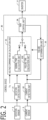
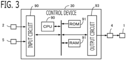
- the control device 30 controls the AC rotary machine 1 via the inverter 4. As shown in FIG. 2 , the control device 30 is provided with a rotation detection unit 31, a current detection unit 32, a voltage command value calculation unit 33, a PWM control unit 34, a failure determination unit 35, and the like. Respective functions of the control device 30 are realized by processing circuits provided in the control device 30. Specifically, as shown in FIG.
- the control device 30 is provided, as processing circuits, with an arithmetic processor (computer) 90 such as a CPU (Central Processing Unit), storage apparatuses 91 which exchange data with the arithmetic processor 90, an input circuit 92 which inputs external signals to the arithmetic processor 90, an output circuit 93 which outputs signals from the arithmetic processor 90 to the outside, and the like.
- arithmetic processor computer
- CPU Central Processing Unit
- ASIC Application Specific Integrated Circuit
- IC Integrated Circuit
- DSP Digital Signal Processor
- FPGA Field Programmable Gate Array
- various kinds of logical circuits various kinds of signal processing circuits, and the like
- arithmetic processor 90 a plurality of the same type ones or the different type ones may be provided, and each processing may be shared and executed.
- a RAM Random Access Memory
- ROM Read Only Memory
- the input circuit 92 is connected with various kinds of sensors and switches such as the rotation sensor 2 and the current sensor 5, and is provided with A/D converter and the like for inputting output signals from the sensors and the switches to the arithmetic processor 90.
- the output circuit 93 is connected with electric loads such as a gate drive circuit which drive on/off of the switching devices, and is provided with a driving circuit and the like for outputting a control signal from the arithmetic processor 90.
- the arithmetic processor 90 runs software items (programs) stored in the storage apparatus 91 such as a ROM and collaborates with other hardware devices in the control device 30, such as the storage apparatus 91, the input circuit 92, and the output circuit 93, so that the respective functions of the control units 31 to 35 of FIG. 2 provided in the control device 30 are realized.
- Setting data items such as the voltage command value at failure to be used in the control units 31 to 35 are stored, as part of software items (programs), in the storage apparatus 91 such as a ROM.
- the rotation detection unit 31 detects a magnetic pole position ⁇ (a rotational angle ⁇ of the rotor) and a rotational angle speed ⁇ of the rotor in an electrical angle.
- the rotation detection unit 31 detects the magnetic pole position ⁇ (the rotational angle ⁇ ) and the rotational angle speed ⁇ of the rotor, based on the output signal of the rotation sensor 2.
- the magnetic pole position is set in the direction of the N pole of the permanent magnet provided in the rotor.
- the rotation detection unit 31 may estimate the rotational angle (the magnetic pole position) without using the rotation sensor, based on current information which are obtained by superimposing a harmonic wave component on the current command value (so-called, sensorless system).
- the current detection unit 32 detects currents Iu, Iv, Iw which flow into respective phases of the three-phase windings, based on the output signal of the current sensor 5.
- the current detection unit 32 detects current Iu which flows into the winding of U phase based on the output signal of the current sensor 5u of U phase; detects current Iv which flows into the winding of V phase based on the output signal of the current sensor 5v of V phase; and detects current Iw which flows into the winding of W phase based on the output signal of the current sensor 5w of W phase.
- the current sensor 5 is connected in series to the negative electrode side switching device SN.
- the current detection unit 32 detects current at the timing when the negative electrode side switching device SN is turned on. In the present embodiment, the current detection unit 32 detects current at the timing of every PWM period when a carrier wave CA describes below becomes a peak point of mountain. The current detection unit 32 holds the detected current detection value of each phase until next current detection timing.
- the failure determination unit 35 determines a positive electrode side short circuit failure which is a short circuit failure of a part of the positive electrode side switching device, and a negative electrode side short circuit failure which is a short circuit failure of a part of the negative electrode side switching device, in the series circuit of each phase of the inverter 4.
- the failure determination unit 35 determines, about each phase, that the positive electrode side short circuit failure occurred, when determining that a short circuit failure in which the positive electrode side switching device always turns on, or a short circuit failure in which a connection path between the series circuit and the winding short-circuits to a positive electrode side of the DC power source occurred. And, the failure determination unit 35 determines, about each phase, that the negative electrode side short circuit failure occurred, when determining that a short circuit failure in which the negative electrode side switching device always turns on, or a short circuit failure in which a connection path between the series circuit and the winding short-circuits to a negative electrode side of the DC power source occurred.
- the failure determination unit 35 determines occurrence of the positive electrode side short circuit failure and the negative electrode side short circuit failure of each phase, based on on-off pattern of the positive electrode side and the negative electrode side switching devices of each phase, and the current detection value of each phase. For example, the failure determination units 35 determines that the positive electrode side short circuit failure or the negative electrode side short circuit failure corresponding to the on-off pattern occurred, when the current detection value of each phase deviates from a normal range of the current detection value of each phase which is determined based on the on-off pattern of each switching device. Various kinds of well-known methods are used for determination.
- the failure determination unit 35 may determine the short circuit failure of each switching device, based on the failure detection result by the failure detection circuit.
- the failure determination unit 35 determines failure of the series circuit of each phase of the normal two phases, based on current detection values of the normal two phases. For example, when the current detection values of the normal two phases deviate from the normal ranges of current detection value of respective phases which are determined based on the on-off pattern of each switching device, the failure determination unit 35 determines that the positive electrode side short circuit failure or the negative electrode side short circuit failure corresponding to the on-off pattern occurred.
- the PWM control unit 34 controls on/off the switching devices of each phase by PWM control (Pulse Width Modulation), based on the voltage command value Vu, Vv, Vw of each phase calculated by the voltage command value calculation unit 33 described below.
- PWM control Pulse Width Modulation
- the PWM control unit 34 compares the voltage command value Vu, Vv, Vw of each phase with a carrier wave CA which vibrates between 0 and the DC voltage Vdc at a control period Tc of the PWM control (hereinafter, referred to as PWM period Tc); and controls on/off the switching devices of each phase, based on a comparison result.
- the carrier wave CA is a triangular wave which vibrates between 0 and the DC voltage Vdc at the PWM period Tc.
- the PWM control unit 34 turns on the switching signal GP of the positive electrode side switching device (in this example, 1) and turns on the positive electrode side switching device when the carrier wave CA is less than the voltage command value; and turns off the switching signal GP of the positive electrode side switching device (in this example, 0) and turns off the positive electrode side switching device when the carrier wave CA exceeds the voltage command value.
- the PWM control unit 34 turns off the switching signal GN of the negative electrode side switching device (in this example, 0) and turns off the negative electrode side switching device when the carrier wave CA is less than the voltage command value; and turns on the switching signal GN of the negative electrode side switching device (in this example, 1) and turns on the negative electrode side switching device when the carrier wave CA exceeds the voltage command value.
- a short circuit prevention period (dead time) which turns off both of the positive electrode side and the negative electrode side switching device may be provided.
- the negative electrode side switching signals GNu, GNv, GNw of all three-phase are turned on.
- currents which flow into the three-phase windings can be detected by the current sensor 5.
- the current detection unit 32 detects the currents at the timing of the peak point of mountain of the carrier wave CA.
- the negative electrode side switching device becomes on when the voltage command value is smaller than the DC voltage Vdc, current can be detected by the current sensor.
- current cannot be detected correctly if the on period of the negative electrode side switching device is too short, it is necessary to set the on period of the negative electrode side switching device longer than or equal to a length necessary for current detection. This is because there is a stabilization time delay Tdly until current which flows through the negative electrode side switching device is stabilized, due to influence of ringing and the like, after turning on the negative electrode side switching device. Accordingly, current cannot be detected correctly, if current is detected before the stabilization time delay Tdly elapses after turning on the negative electrode side switching device.
- the center of the on period of the negative electrode side switching device becomes the current detection timing, it is necessary to set the on period of the negative electrode side switching device to a double value of the stabilization time delay Tdly or more.
- the double value of stabilization time delay Tdly corresponds to the length necessary for current detection. Accordingly, until the on period Ton of the negative electrode side switching device becomes the double value of stabilization time delay Tdly, the voltage command value needs to be decreased by a decrease amount ⁇ Vdwn from the DC voltage Vdc.
- the decrease amount ⁇ Vdwn and the upper limit value Vup of voltage command value necessary for current detection becomes the next equation.
- the decrease amount ⁇ Vdwn becomes 10% of the DC voltage Vdc, and the upper limit value Vup is set to 90% of the DC voltage Vdc.
- the voltage command value of one phase becomes larger than the upper limit value Vup and the current of its phase cannot be detected, the voltage command value of the remaining two phases becomes less than or equal to the upper limit value Vup usually. Accordingly, by utilizing Kirchhoff's law that a total value of currents of three-phase becomes 0, the current of one phase can be calculated from the current detection values of two phases. Alternatively, by adding modulation to the voltage command values of three-phase so that the voltage command values do not become larger than the upper limit value Vup, the currents of three-phase can be detected.
- the voltage command value calculation unit 33 calculates the voltage command value of each phase applied to the winding of each phase.
- the voltage command value calculation unit 33 is provided with a normal time calculation unit 331 that calculates the voltage command values when failure is not determined by the failure determination unit 35, and a failure time calculation unit 332 that calculates the voltage command values when failure is determined by the failure determination unit 35.
- the normal time calculation unit 331 calculates the voltage command value of each phase, when failure is not determined by the failure determination unit 35.
- the normal time calculation unit 331 calculates the voltage command values of three-phase Vu, Vv, Vw by well-known vector control.
- the normal time calculation unit 331 converts the current detection values of three-phase into current detection values of d-axis and q-axis Id, Iq based on the rotational angle ⁇ ; changes the voltage command values of d-axis and q-axis Vd, Vq so that the current detection values of d-axis and q-axis Id, Iq approach the current command values of d-axis and q-axis Ido, Iqo, respectively; and converts the voltage command values of d-axis and q-axis Vd, Vq into the voltage command values of three-phase Vu, Vv, Vw based on the rotational angle ⁇ .
- Modulation may be added to the voltage command values of three-phase Vu, Vv, Vw.
- the voltage command values of three-phase Vu, Vv, Vw are calculated so as to vibrate within a range from 0 to the DC voltage Vdc.
- the normal time calculation unit 331 sets the current command values of d-axis and q-axis Ido, Iqo, using the method of various kinds of vector control, based on the torque command value To.
- the failure time calculation unit 332 calculates the voltage command value of each phase, when failure is determined by the failure determination unit 35. When it is determined that the positive electrode side short circuit failure or the negative electrode side short circuit failure of the series circuit of any one phase occurred, the failure time calculation unit 332 calculates the voltage command values of the normal two phases that the short circuit failure do not occur.
- the positive electrode side switching devices of three-phase or the negative electrode side switching devices of three-phase are turned on at the time of failure like patent document 1, the three-phase windings are mutually short-circuited, a brake torque is generated, and an adverse influence is given on a power apparatus to which torque of the AC rotary machine 1 is outputted. Then, in the present embodiment, the voltage command values of the normal two phases which do not generate the brake torque are calculated.
- an induction current which becomes a source of the brake torque can be calculated from the rotational angle ⁇ and the rotational angle speed ⁇ . Accordingly, based on at least the rotational angle ⁇ , the voltage command values which suppress generation of the brake torque and generates the torque close to the torque command value To can be calculated.
- the failure time calculation unit 332 sets the voltage command value of the abnormal phase in which the short circuit failure occurred, to the DC voltage Vdc; and calculates the voltage command values of the normal two phases which vibrate on a basis of the DC voltage Vdc according to the rotational angle ⁇ .
- the failure time calculation unit 332 sets the voltage command value of the abnormal phase in which the short circuit failure occurred, to 0; and calculates the voltage command values of the normal two phases which vibrate on a basis of 0 according to the rotational angle ⁇ .
- the failure time calculation unit 332 calculates basic values of voltage command value of the normal two phases which vibrate on a basis of a half value of the DC voltage Vdc; and makes the basic values of voltage command value of the normal two phases offset by the half value of the DC voltage Vd in a positive side or a negative side, according to the positive electrode side short circuit failure or the negative electrode side short circuit failure. The details will be explained below.
- FIG. 5 shows a control block diagram indicating processing when the positive electrode side short circuit failure or the negative electrode side short circuit failure of V phase occurs.
- the failure time calculation unit 332 is provided with a normal phase basic value calculation unit 3321, an abnormal phase command value calculation unit 3322, and a normal phase command value calculation unit 3323.
- the normal phase basic value calculation unit 3321 calculates the basic values of voltage command value of the normal two phases which vibrate on the basis of the half value of the DC voltage Vdc according to the rotational angle ⁇ . For example, by referring to a basic value setting data in which a relationship between the rotational angle ⁇ and the voltage command values of the normal two phases is preliminarily set, the normal phase basic value calculation unit 3321 calculates the basic values of voltage command value of the normal two phases corresponding to the present rotational angle ⁇ .
- the basic value setting data is preliminarily set for each of a plurality of the rotational angle speeds ⁇ , and the basic value setting data corresponding to the present rotational angle speed ⁇ is used. An arithmetic expression may be used instead of the basic value setting data.
- the basic value setting data is set for each combination of the normal two phases.
- U phase fails, the basic value setting data of V phase and W phase in which a relationship between the rotational angle ⁇ and the voltage command values of V phase and W phase is preliminarily set is referred.
- V phase fails, the basic value setting data of U phase and W phase in which a relationship between the rotational angle ⁇ and the voltage command values of U phase and W phase is preliminarily set is referred.
- W phase fails, the basic value setting data of U phase and V phase in which a relationship between the rotational angle ⁇ and the voltage command values of U phase and V phase is preliminarily set is referred.
- the normal phase basic value calculation unit 3321 increases or decreases amplitudes of the basic values of voltage command value of the normal two phases, centering on the half value of the DC voltage Vdc, according to the torque command value To.
- the torque command value To may be calculated inside the control device 30, or may be transmitted from the outside of the control device 30.
- a torque current command value which is a current command value corresponding to torque may be used.
- the abnormal phase command value calculation unit 3322 sets the voltage command value of the abnormal phase in which the short circuit failure occurred, to the DC voltage Vdc. Then, the normal phase command value calculation unit 3323 makes the basic values of voltage command value of the normal two phases offset by the half value of the DC voltage Vdc in the positive direction, and calculates the voltage command values of the normal two phases.
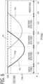
- FIG. 6 shows calculation example of the voltage command value Vv of abnormal V phase, and the voltage command values Vu, Vw of normal U phase and V phase after offset, when it is determined that the positive electrode side short circuit failure of V phase occurred.
- the horizontal axis is the rotational angle ⁇ .
- the negative electrode side switching device of the abnormal phase is always turned off by the PWM control, the series circuit of the abnormal phase is short-circuited, and a large current can be prevented from flowing.
- the failure time calculation unit 332 may always turn off the negative electrode side switching device of the abnormal phase, without setting the voltage command value of the abnormal phase and performing the PWM control.
- the positive electrode side switching device of the abnormal phase may always be turned off on the safe side. In this case, it corresponds that the voltage command value of the abnormal phase is set to the DC voltage Vdc.
- the voltage command values of the normal two phases are different from the voltage command value of the abnormal phase, current flows according to a voltage difference between phases. Since the voltage command value of the abnormal phase is set to the DC voltage Vdc, the voltage difference in the same direction always occurs between the voltage command value of the abnormal phase, and the basic values of voltage command value of the normal two phases which vibrates on the basis of the half value of the DC voltage Vdc, and the current in the same direction flows. Accordingly, it is not desirable. Therefore, by making the basic values of voltage command value of the normal two phases offset by the half value of the DC voltage Vdc in the positive direction like the above configuration, the voltage command values of the normal two phases can be vibrated on the basis of the DC voltage Vdc.
- the voltage command values of the normal two phases are also upper-limited by the DC voltage Vdc.
- the voltage command values of the normal two phases do not need to be upper-limited by the DC voltage Vdc, since the voltage command values are compared with the carrier wave CA which vibrates between 0 and the DC voltage Vdc, the result of PWM control becomes the same.
- the voltage command values of the normal two phases coincide with the DC voltage Vdc which is the same as the voltage command value of the abnormal phase, the voltage difference between phases does not occur, and current can be prevented from flowing according to the voltage difference between phases.
- the voltage command values of the normal two phases become smaller than the DC voltage Vdc, current for generating torque according to the torque command value To can be flowed.
- the voltage command value of one normal phase may be set to the DC voltage Vdc, and the voltage command value of the other normal phase may be decreased from the DC voltage Vdc.
- the abnormal phase command value calculation unit 3322 sets the voltage command value of the abnormal phase in which the short circuit failure occurred, to 0. Then, the normal phase command value calculation unit 3323 makes the basic values of voltage command value of the normal two phases offset by the half value of the DC voltage Vdc in the negative direction, and calculates the voltage command values of the normal two phases.
- FIG. 7 shows calculation example of the voltage command value Vv of abnormal V phase, and the voltage command values Vu, Vw of normal U phase and V phase after offset, when it is determined that the negative electrode side short circuit failure of V phase occurred.
- the horizontal axis is the rotational angle ⁇ .
- the positive electrode side switching device of the abnormal phase is always turned off by the PWM control, the series circuit of the abnormal phase is short-circuited, and a large current can be prevented from flowing.
- the failure time calculation unit 332 may always turn off the positive electrode side switching device of the abnormal phase, without setting the voltage command value of the abnormal phase and performing the PWM control.
- the negative electrode side switching device of the abnormal phase may always be turned off on the safe side. In this case, it corresponds that the voltage command value of the abnormal phase is set to 0.
- the voltage command values of the normal two phases are different from the voltage command value of the abnormal phase, current flows according to a voltage difference between phases. Since the voltage command value of the abnormal phase is set to 0, the voltage difference in the same direction always occurs between the voltage command value of the abnormal phase, and the basic values of voltage command value of the normal two phases which vibrates on the basis of the half value of the DC voltage Vdc, and the current in the same direction flows. Accordingly, it is not desirable. Therefore, by making the basic values of voltage command value of the normal two phases offset by the half value of the DC voltage Vdc in the negative direction like the above configuration, the voltage command values of the normal two phases can be vibrated on the basis of 0.
- the voltage command values of the normal two phases are also lower-limited by 0. Although the voltage command values of the normal two phases do not need to be lower-limited by 0, since the voltage command values are compared with the carrier wave CA which vibrates between 0 and the DC voltage Vdc, the result of PWM control becomes the same.
- the voltage command calculation unit 332 changes the voltage command values of the normal two phases so that on period of the negative electrode side switching device of each phase of the normal two phases become longer than or equal to a length necessary for current detection at least at a current detection timing.
- the failure determination unit 35 can determine failure of the series circuits of the normal two phases using the current detection values of the normal two phases. Accordingly, reliability of operation of the AC rotary machine at the time of failure occurrence can be improved more.
- the detection object device is the negative electrode side switching device.
- the failure time calculation unit 332 upper-limits the voltage command values of the normal two phases by an upper limit value Vup which is set to a value smaller than the DC voltage Vdc so that the on period of the negative electrode side switching device of each phase of the normal two phases becomes longer than or equal to the length necessary for current detection.
- the upper limit value Vup is set as explained using the equation (1).
- only the voltage command value which exceeds the upper limit value Vup may be set to the upper limit value Vup; or the voltage command values of the normal two phases may be decreased by the same offset voltage so that the voltage command values of the normal two phases do not exceed the upper limit value Vup; or a coefficient smaller than one may be multiplied to the voltage command values of the normal two phases.
- the voltage command values of the normal phases are always upper-limited by the upper limit value Vup which is set to 90% of the DC voltage Vdc. Accordingly, the negative electrode side switching device is turned on at the vicinity of the peak point of mountain of the carrier wave CA of each PWM period Tc, and current flows through the current sensor. In the figure, the behavior until current is stabilized after turning on the switching device is omitted. Current can be detected at the peak point of mountain of the carrier wave CA of each PWM period Tc. The current detection value is held until the next current detection timing.
- the current detection unit 32 may detect the output signal of the current sensor at the timing when current is not flowing into the current sensor. In this case, when it is determined that the short circuit failure occurred, the failure time calculation unit 332 may lower-limit the voltage command values of the normal two phases by a lower limit value which is set to a value larger than 0 so that the off period of the negative electrode side switching device of each phase of the normal two phases may be generated. Especially, when it is determined that the negative electrode side short circuit failure occurred, since the voltage command values of the normal two phases vibrate on the basis of 0, the frequency of becoming 0 becomes high, and it is necessary to lower-limit by the lower limit value. In the case of lower-limiting by the lower limit value, the current detection unit 32 may detect the output signal of the current sensor at the peak point of valley of the carrier wave CA.
- Embodiment 2 The controller 10 according to Embodiment 2 will be explained. The explanation for constituent parts the same as those in Embodiment 1 will be omitted.
- the basic configuration of the AC rotary machine 1 and the controller 10 according to the present embodiment is the same as that of Embodiment 1.
- Embodiment 2 is different from Embodiment 1 in that the voltage command values are calculated by using the current detection values of the normal two phases at the time of the short circuit failure.
- the voltage command value calculation unit 33 calculates the voltage command values of the normal two phases, based on the current detection values of the normal two phases.
- FIG. 9 shows a control block diagram indicating processing when the positive electrode side short circuit failure or the negative electrode side short circuit failure of V phase occurs. It is configured similarly to FIG. 9 of the patent document 2.
- the failure time calculation unit 332 is provided with a normal phase current command value calculation unit 3320, a normal phase basic value calculation unit 3321, an abnormal phase command value calculation unit 3322, and a normal phase command value calculation unit 3323.
- the current command value setting data is set for each combination of the normal two phases.
- U phase fails, the current command value setting data of V phase and W phase in which a relationship between the rotational angle ⁇ and the current command values of V phase and W phase is preliminarily set is referred.
- V phase fails, the current command value setting data of U phase and W phase in which a relationship between the rotational angle ⁇ and the current command values of U phase and W phase is preliminarily set is referred.
- W phase fails, the current command value setting data of U phase and V phase in which a relationship between the rotational angle ⁇ and the current command values of U phase and V phase is preliminarily set is referred.
- the normal phase current command value calculation unit 3320 increases or decreases the amplitudes of the current command values of the normal two phases centering on 0, according to the torque command value To.
- the normal phase basic value calculation unit 3321 performs a current feedback control which changes basic values of voltage command value of the normal two phases so that the current detection values of the normal two phases approach the current command values of the normal two phases, respectively. For example, when V phase fails, the normal phase basic value calculation unit 3321 changes the basic value of voltage command value Vu0 of U phase so that the current detection value of U phase Iu approaches the current command value Iuo of U phase, and changes the basic value of voltage command value Vw0 of W phase so that the current detection value Iw of W phase approaches the current command value Iwo of W phase.
- PI control based on a current deviation or the like is used.
- the abnormal phase command value calculation unit 3322 sets the voltage command value of the abnormal phase in which the short circuit failure occurred, to the DC voltage Vdc.
- the normal phase command value calculation unit 3323 makes the basic values of voltage command value of the normal two phases offset by the half value of the DC voltage Vdc in the positive direction, and calculates the voltage command values of the normal two phases.
- the voltage command values of the normal two phases of the present embodiment become the similar behavior as FIG. 6 of Embodiment 1.
- the voltage command values of the normal two phases By making the basic values of voltage command value of the normal two phases offset by the half value of the DC voltage Vdc in the positive direction, the voltage command values of the normal two phases can be vibrated on the basis of the DC voltage Vdc. Accordingly, torque can be generated according to the torque command value To as much as possible, while suppressing increase in winding current.
- the abnormal phase command value calculation unit 3322 sets the voltage command value of the abnormal phase in which the short circuit failure occurred, to 0.
- the normal phase command value calculation unit 3323 makes the basic values of voltage command value of the normal two phases offset by the half value of the DC voltage Vdc in the negative direction, and calculates the voltage command values of the normal two phases.
- the voltage command values of the normal two phases of the present embodiment become the similar behavior as FIG. 7 of Embodiment 1.
- the voltage command values of the normal two phases can be vibrated on the basis of 0. Accordingly, torque can be generated according to the torque command value To as much as possible, while suppressing increase in winding current.
- the voltage command calculation unit 332 changes the voltage command values of the normal two phases so that on period of the negative electrode side switching device of each phase of the normal two phases become longer than or equal to a length necessary for current detection at least at a current detection timing.
- the failure time calculation unit 332 upper-limits the voltage command values of the normal two phases by the upper limit value Vup which is set to a value smaller than the DC voltage Vdc so that the on period of the negative electrode side switching device of each phase of the normal two phases becomes longer than or equal to the length necessary for current detection.
- the on periods of the negative electrode side switching devices of the normal two phases can be set longer than or equal to the length necessary for current detection, and currents of the normal two phases can be detected with good accuracy.
- the failure determination unit 35 may determine failure of the series circuits of the normal two phases using the current detection values of the normal two phases similarly to Embodiment 1, or may not determine failure of the series circuits of the normal two phases unlike Embodiment 1.
- Embodiment 3 The controller 10 according to Embodiment 3 will be explained. The explanation for constituent parts the same as those in Embodiment 1 will be omitted.
- the basic configuration of the AC rotary machine 1 and the controller 10 according to the present embodiment is the same as that of Embodiment 1.
- Embodiment 3 is different from Embodiment 1 in that currents are detected for every a plurality of PWM periods, and the voltage command values are changed.
- the current detection unit 32 detects current for every a plurality of PWM periods. When it is not determined that the short circuit failure occurred, the current detection unit 32 detects current for every PWM period.
- the current detection unit 32 detects current at the peak point of mountain of the carrier wave CA of every five PWM periods.
- the voltage command calculation unit 332 changes the voltage command values of the normal two phases so that the on period of the negative electrode side switching device of each phase of the normal two phases become longer than or equal to the length necessary for current detection at a current detection timing of every the plurality of PWM periods (in this example, every five PWM periods).
- the detection object device is the negative electrode side switching device.
- the failure time calculation unit 332 upper-limits the voltage command values of the normal two phases by an upper limit value Vup which is set to a value smaller than the DC voltage Vdc so that the on period of the negative electrode side switching device of each phase of the normal two phases becomes longer than or equal to the length necessary for current detection at the current detection timing of every the plurality of PWM periods.
- a frequency where the voltage command value is upper-limited by the upper limit value Vup can be decreased. Accordingly, a frequency of the decrease of torque and the increase of current can be decreased, and an average decrease amount of torque and an average increase amount of current can be decreased according to the frequency. For example, when upper-limiting every five PWM periods, the average decrease amount of torque and the average increase amount of current can be decreased to 1/5, compared with when upper-limiting every PWM period.
- the voltage command value is lower than the upper limit value Vup, since the upper limitation is not performed, the influence of frequency of current detection does not occur.
- the failure time calculation unit 332 turns on an execution flag of limitation of voltage command value at the current detection timing of every five PWM periods.
- the failure time calculation unit 332 turns on the execution flag during an on period centering on the peak point of mountain of the carrier wave CA which is the current detection timing.
- the on period of the execution flag is set longer than an on period of the negative electrode side switching device corresponding to the upper limit value Vup.
- the failure time calculation unit 332 upper-limits the voltage command values of the normal two phases by the upper limit value Vup.
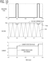
- FIG. 10 shows the voltage command value of normal one phase which is set to the DC voltage Vdc.
- the voltage command value is upper-limited by the upper limit value Vup, and the voltage command value is set to the upper limit value Vup. Accordingly, the on period of the negative electrode side switching device becomes longer than or equal to the length necessary for current detection at the current detection timing of every five PWM periods, and current can be detected with good accuracy.
- the current detection unit 32 holds the detected current detection value of each phase until next current detection timing after five PWM periods.
- the current detection unit 32 may detect current for every PWM period.
- the current detection unit 32 may calculate the current detection value, based on a plurality of past current detection values. For example, the current detection unit 32 may calculate the current detection value by performing a prediction such as a first order prediction or a second order prediction, based on the plurality of past current detection values; or may calculate the current detection value by performing a low pass filter processing to the plurality of past current detection values. According to this configuration, In PWM period when current is not detected, the current detection value can be changed smoothly, and can be used for each processing.
- the plurality of PWM periods (the sampling period of current) for detecting current is set shorter than a response time constant of a control system which controls current flowing through the winding.
- the response time constant is defined as a time after performing step change of the current command value until the current detection value reaches 63.2% of the final value.
- the response time constant corresponds to a reciprocal of a cutoff frequency of the current feedback control system.
- Embodiment 4 The controller 10 according to Embodiment 4 will be explained. The explanation for constituent parts the same as those in Embodiment 1 will be omitted.
- the basic configuration of the AC rotary machine 1 and the controller 10 according to the present embodiment is the same as that of Embodiment 1.
- Embodiment 4 is different from Embodiment 1 in that PWM period is lengthened when the short circuit failure occurs.
- the PWM control unit 34 lengthens the PWM period Tc longer than when it is not determined that the short circuit failure occurred.
- the upper limit value Vup can be increased more than when the PWM period Tc is not lengthened, and the decrease amount of torque and the increase amount of current by the upper limitation of voltage command value can be decreased.
- the PWM period Tc at the normal time is set to 50 microseconds
- the PWM period Tc at the failure time is set to 250 microseconds.
- An on period Ton of the negative electrode side switching device necessary for current detection is 5 microseconds. If the PWM period Tc at the failure time is set to 50 microseconds without changing from the normal time, the decrease amount ⁇ Vdwn is 10% of the DC voltage Vdc. But, if the PWM period Tc at the failure time is lengthened from the normal time and is set to 250 microseconds, the decrease amount ⁇ Vdwn becomes 2% of the DC voltage Vdc. Accordingly, compared with when the PWM period Tc at the failure time is not changed from the normal time, the decrease amount of torque and the increase amount of current can be decreased to 1/5.
- the sampling period of current changes in proportion to the PWM period Tc. If the sampling frequency of current decreases, Nyquist frequency decreases. Accordingly, if the PWM period Tc is lengthened too much, the stability of the current feedback control system will be deteriorated.
- the PWM period Tc (the sampling period of current) is set shorter than the response time constant of the control system which controls current flowing through the winding.
- the response time constant is defined as a time after performing step change of the current command value until the current detection value reaches 63.2% of the final value.
- the response time constant corresponds to a reciprocal of a cutoff frequency of the current feedback control system.
- the current feedback control system can be prevented from being destabilized.
- Embodiment 5 The controller 10 according to Embodiment 5 will be explained. The explanation for constituent parts the same as those in Embodiment 1 will be omitted.
- the basic configuration of the AC rotary machine 1 and the controller 10 according to the present embodiment is the same as that of Embodiment 1.
- Embodiment 5 is different from Embodiment 1 in that the current sensor is connected in series to the positive electrode side switching device, and the detection object device is the positive electrode side switching device.
- FIG. 11 is a schematic configuration diagram of the AC rotary machine 1 and the controller 10 according to the present embodiment.
- the current sensor 5 of each phase is connected in series to the positive electrode side of the positive electrode side switching device SP of each phase.
- the current sensor 5 of each phase may be connected in series to the negative electrode side of the positive electrode side switching device SP of each phase. Accordingly, the current sensor 5 of each phase can detect the current which flows through the positive electrode side switching device SP of each phase.
- the positive electrode side switching signals GPu, GPv, GPw of all three-phase are turned on.
- currents which flow into the three-phase windings can be detected by the current sensor 5.
- the current detection unit 32 detects current at the timing of the peak point of valley of the carrier wave CA.
- the positive electrode side switching device since the positive electrode side switching device is turned on if the voltage command value is set larger than 0, current can be detected by the current sensor. However, since current cannot be detected correctly if the on period of the positive electrode side switching device is too short, it is necessary to set the on period of the positive electrode side switching device longer than or equal to the length necessary for current detection. This is because there is a stabilization time delay Tdly until current which flows through the positive electrode side switching device is stabilized, due to influence of ringing and the like, after turning on the positive electrode side switching device. Accordingly, current cannot be detected correctly, if current is detected before the stabilization time delay Tdly elapses after turning on the positive electrode side switching device.
- the center of the on period of the positive electrode side switching device becomes the current detection timing, it is necessary to set the on period of the positive electrode side switching device to a double value of the stabilization time delay Tdly or more.
- the double value of stabilization time delay Tdly corresponds to the length necessary for current detection. Accordingly, until the on period Ton of the positive electrode side switching device becomes the double value of stabilization time delay Tdly, the voltage command value needs to be increased by an increase amount ⁇ Vup from 0.
- the increase amount ⁇ Vup and the lower limit value Vdwn of voltage command value necessary for current detection becomes the next equation.
- the increase amount ⁇ Vup becomes 10% of the DC voltage Vdc
- the lower limit value Vdwn is set to 10% of the DC voltage Vdc.
- the detection object device is the positive electrode side switching device.
- the failure time calculation unit 332 lower-limits the voltage command values of the normal two phases by the lower limit value Vdwn which is set to a value larger than 0 so that the on period of the positive electrode side switching device of each phase of the normal two phases becomes longer than or equal to the length necessary for current detection.
- the lower limit value Vdwn is set as explained using the equation (2).
- the voltage command value calculation unit 33 may calculate the voltage command values of the normal two phases, based on the current detection values of the normal two phases.
- the current detection unit 32 may detect current at the peak point of valley of the carrier wave CA of every a plurality of PWM periods.
- the voltage command calculation unit 332 may changes the voltage command values of the normal two phases so that the on period of the positive electrode side switching device of each phase of the normal two phases become longer than or equal to the length necessary for current detection at the current detection timing of every the plurality of PWM periods.
- the PWM control unit 34 may lengthen the PWM period Tc longer than when it is not determined that the short circuit failure occurred.
- Embodiment 6 The controller 10 according to Embodiment 6 will be explained. The explanation for constituent parts the same as those in Embodiment 1 will be omitted.
- the basic configuration of the AC rotary machine 1 and the controller 10 according to the present embodiment is the same as that of Embodiment 1.
- Embodiment 6 is different from Embodiment 1 in that the AC rotary machine 1 is a driving force source of an electric power steering apparatus.
- FIG. 14 is a schematic configuration diagram of the electric power steering apparatus, the AC rotary machine 1, and the controller 10 according to the present embodiment.
Landscapes
- Engineering & Computer Science (AREA)
- Power Engineering (AREA)
- Control Of Ac Motors In General (AREA)
- Control Of Electric Motors In General (AREA)
Claims (12)
- Eine Steuereinheit (10) für eine Wechselstrom-Rotationsmaschine, die so konfiguriert ist, dass sie eine Wechselstrom-Rotationsmaschine (1) steuert, die mit n-Phasen-Wicklungen versehen ist, wobei n eine natürliche Zahl und größer oder gleich drei ist, wobei die Steuereinheit (10) für eine Wechselstrom-Rotationsmaschine Folgendes umfasst:einen Wechselrichter (4), der mit n Sätzen von Reihenschaltungen vorgesehen ist, in denen jeweils eine positiv-elektrodenseitige Schaltvorrichtung (SP), die einer positiven Elektrodenseite einer Gleichstromquelle (3) zugehört, und eine negativ-elektrodenseitige Schaltvorrichtung (SN), die einer negativen Elektrodenseite der Gleichstromquelle (3) zugehört, in Reihe geschaltet sind, und ein Verbindungsknoten der Reihenschaltung mit der Wicklung der entsprechenden Phase verbunden ist, entsprechend zu jeder Phase von n-Phasen;n-Phasen-Stromsensoren (5), von denen jeder in Reihe mit einer Erkennungszielvorrichtung verbunden ist, die die positiv-elektrodenseitige Schaltvorrichtung (SP) oder die negativ-elektrodenseitige Schaltvorrichtung (SN) jeder Phase von n-Phasen ist, und so konfiguriert ist, dass er Strom erkennt;eine Stromerkennungseinheit (32), die so konfiguriert ist, dass sie den Strom jeder Phase auf der Grundlage eines Ausgangssignals des Stromsensors jeder Phase zu einem Zeitpunkt erkennt, wenn die Erkennungszielvorrichtung jeder Phase eingeschaltet ist;eine Spannungsbefehlswert-Berechnungseinheit (33), die so konfiguriert ist, dass sie einen Spannungsbefehlswert jeder Phase berechnet, der an die Wicklung jeder Phase angelegt wird, auf der Grundlage eines Stromerkennungswertes jeder Phase;eine PWM-Steuereinheit (34), die so konfiguriert ist, dass sie die Schaltvorrichtungen jeder Phase durch PWM-Steuerung auf der Grundlage des Spannungsbefehlswerts jeder Phase ein- und ausschaltet; undeine Fehlerbestimmungseinheit (35), die so konfiguriert ist, dass sie einen positiv-elektrodenseitigen Kurzschlussfehler, bei dem es sich um einen Kurzschlussfehler eines Abschnitts der positiv-elektrodenseitigen Schaltvorrichtung (SP) handelt, und einen negativelektrodenseitigen Kurzschlussfehler, bei dem es sich um einen Kurzschlussfehler eines Abschnitts der negativelektrodenseitigen Schaltvorrichtung (SN) handelt, in der Serienschaltung jeder Phase des Wechselrichters (4) auf der Grundlage eines Ein-Aus-Musters der positiv-elektrodenseitigen Schaltvorrichtung (SP) und der negativelektrodenseitigen Schaltvorrichtung (SN) in jeder Phase und des Stromerfassungswerts jeder Phase erkennt,wobei, wenn festgestellt wird, dass der positiv-elektrodenseitige Kurzschlussfehler oder der negativ-elektrodenseitige Kurzschlussfehler der Reihenschaltung einer beliebigen Phase aufgetreten ist, die Spannungsbefehlswert-Berechnungseinheit (33) so konfiguriert ist, dass sie die Spannungsbefehlswerte der normalen n-1 Phasen berechnet, in denen der Kurzschlussfehler nicht auftritt; und dass sie die Spannungsbefehlswerte der normalen n-1 Phasen so ändert, dass die Einschaltdauer der Erkennungszielvorrichtung jeder Phase der normalen n-1 Phasen länger oder gleich einer Länge wird, die zum Erkennen des Stroms zumindest zu einem Stromerkennungszeitpunkt erforderlich ist,wobei, wenn festgestellt wird, dass der Kurzschlussfehler aufgetreten ist, die PWM-Steuereinheit (34) konfiguriert ist, um die Steuerperiode (Tc) der PWM-Steuerung mehr zu verlängern als wenn nicht festgestellt wird, dass der Kurzschlussfehler aufgetreten ist.
- Steuereinheit (10) für eine Wechselstrom-Rotationsmaschine nach Anspruch 1,wobei in einem Fall, in dem die Erkennungsobjektvorrichtung die negativ-elektrodenseitige Schaltvorrichtung (SN) ist, die PWM-Steuereinheit (34) so konfiguriert ist, dass sie, wenn festgestellt wird, dass der Kurzschlussfehler aufgetreten ist, die Spannungsbefehlswerte der normalen n-1 Phasen durch einen oberen Grenzwert nach oben begrenzt, der auf einen Wert eingestellt ist, der kleiner als eine Gleichspannung (Vdc) der Gleichstromquelle (3) ist, so dass die Einschaltperiode der negativelektrodenseitigen Schaltvorrichtung (SN) jeder Phase der normalen n-1 Phasen länger als oder gleich der Länge wird, die zum Erkennen des Stroms erforderlich ist; undin einem Fall, in dem die Erkennungsobjektvorrichtung die positiv-elektrodenseitige Schaltvorrichtung (SP) ist, wenn festgestellt wird, dass der Kurzschlussfehler aufgetreten ist, die PWM-Steuereinheit (34) so konfiguriert ist, dass sie die Spannungsbefehlswerte der normalen n-1 Phasen um einen unteren Grenzwert herabsetzt, der auf einen Wert größer als 0 eingestellt ist, so dass die Einschaltdauer der positiv-elektrodenseitigen Schaltvorrichtung (SP) jeder Phase der normalen n-1 Phasen länger als oder gleich der für die Stromerkennung erforderlichen Länge wird.
- Steuereinheit (10) für eine Wechselstrom-Rotationsmaschine nach Anspruch 1 oder 2,wobei die Stromerkennungseinheit (32) so konfiguriert ist, dass sie den Strom für jede Vielzahl von Steuerperioden (Tc) der PWM-Steuerung erkennt, undwobei die Spannungsbefehlswert-Berechnungseinheit (33) so konfiguriert ist, dass sie die Spannungsbefehlswerte der normalen n-1 Phasen so ändert, dass die Einschaltperiode der Erkennungszielvorrichtung jeder Phase der normalen n-1 Phasen länger als oder gleich der Länge wird, die für die Stromerkennung erforderlich ist, und zwar zu einem Stromerkennungszeitpunkt jeder der Vielzahl von Steuerperioden (Tc) der PWM-Steuerung.
- Steuereinheit (10) für eine Wechselstrom-Rotationsmaschine nach Anspruch 3,
wobei die Vielzahl von Steuerperioden (Tc) der PWM-Steuerung zum Erkennen von Strom kürzer ist als eine Reaktionszeitkonstante eines Steuersystems, das den durch die Wicklung fließenden Strom steuert. - Steuereinheit (10) für eine Wechselstrom-Rotationsmaschine nach Anspruch 3 oder 4,
wobei die Stromerkennungseinheit (32) so konfiguriert ist, dass sie einen Stromerkennungswert auf der Grundlage der Vielzahl vergangener Stromerkennungswerte bei der Steuerperiode (Tc) der PWM-Steuerung berechnet, wenn kein Strom erkannt wird. - Steuereinheit (10) für eine Wechselstrom-Rotationsmaschine nach einem der Ansprüche 1 bis 5,wobei, wenn festgestellt wird, dass der positiv-elektrodenseitige Kurzschlussfehler aufgetreten ist, die Spannungsbefehlswert-Berechnungseinheit (33) so konfiguriert ist, dass sie den Spannungsbefehlswert der unregelmäßigen Phase, in der der Kurzschlussfehler aufgetreten ist, auf eine Gleichspannung (Vdc) der Gleichstromquelle (3) setzt und die Spannungsbefehlswerte der normalen n-1 Phasen, die auf der Grundlage der Gleichspannung (Vdc) der Gleichstromquelle (3) schwingen, gemäß einem Drehwinkel (θ) der AC-Rotationsmaschine (1) berechnet; undwenn festgestellt wird, dass der negativ-elektrodenseitige Kurzschlussfehler aufgetreten ist, die Spannungsbefehlswert-Berechnungseinheit (33) so konfiguriert ist, dass sie den Spannungsbefehlswert der unregelmäßigen Phase, in der der Kurzschlussfehler aufgetreten ist, auf 0 setzt und die Spannungsbefehlswerte der normalen n-1 Phasen, die schwingen, auf der Grundlage von 0 gemäß dem Drehwinkel (θ) der Wechselstrom-Rotationsmaschine (1) berechnet.
- Steuereinheit (10) für eine Wechselstrom-Rotationsmaschine nach einem der Ansprüche 1 bis 6,wobei, wenn festgestellt wird, dass der Kurzschlussfehler aufgetreten ist, die Spannungsbefehlswert-Berechnungseinheit (33) so konfiguriert ist, dass sie Basiswerte des Spannungsbefehlswertes der normalen n-1 Phasen berechnet, die schwingen, auf der Grundlage eines Halbwerts einer Gleichspannung (Vdc) der Gleichstromquelle (3) gemäß einem Drehwinkel (θ) der Wechselstrom-Rotationsmaschine (1);wenn festgestellt wird, dass der positiv-elektrodenseitige Kurzschlussfehler aufgetreten ist, die Spannungsbefehlswert-Berechnungseinheit (33) so konfiguriert ist, dass sie die Basiswerte des Spannungsbefehlswertes der normalen n-1 Phasen in einer positiven Richtung um den halben Wert der Gleichspannung (Vdc) der Gleichstromquelle (3) versetzt; undwenn festgestellt wird, dass der negativ-elektrodenseitige Kurzschlussfehler aufgetreten ist, die Spannungsbefehlswert-Berechnungseinheit (33) so konfiguriert ist, dass sie die Basiswerte des Spannungsbefehlswertes der normalen n-1 Phasen in eine negative Richtung um den halben Wert der Gleichspannung (Vdc) der Gleichstromquelle (3) versetzt.
- Steuereinheit (10) für eine Wechselstrom-Rotationsmaschine nach einem der Ansprüche 1 bis 7,
wobei die Fehlerbestimmungseinheit (35) so konfiguriert ist, dass sie einen Fehler der Reihenschaltung jeder Phase der normalen n-1 Phasen auf der Grundlage von Stromerkennungswerten der normalen n-1 Phasen erkennt. - Steuereinheit (10) für eine Wechselstrom-Rotationsmaschine nach einem der Ansprüche 1 bis 8,
wobei, wenn festgestellt wird, dass der Kurzschlussfehler aufgetreten ist, die Spannungsbefehlswert-Berechnungseinheit (33) so konfiguriert ist, dass sie die Spannungsbefehlswerte der normalen n-1 Phasen auf der Grundlage der Stromerkennungswerte der normalen n-1 Phasen berechnet. - Steuereinheit (10) für eine Wechselstrom-Rotationsmaschine nach einem der Ansprüche 1 bis 9,wobei die Fehlerbestimmungseinheit (35) so konfiguriert ist, dass sie für jede Phase bestimmt, dass der positiv-elektrodenseitige Kurzschlussfehler aufgetreten ist, wenn sie bestimmt, dass ein Kurzschlussfehler, bei dem sich die positiv-elektrodenseitige Schaltvorrichtung (SP) immer einschaltet, oder ein Kurzschlussfehler, bei dem ein Verbindungspfad zwischen der Reihenschaltung und der Wicklung zu einer positiven Elektrodenseite der Gleichstromquelle (3) kurzgeschlossen ist, aufgetreten ist; undin Bezug auf jede Phase zu bestimmen, dass der negativ-elektrodenseitige Kurzschlussfehler aufgetreten ist, wenn festgestellt wird, dass ein Kurzschlussfehler, bei dem die negativ-elektrodenseitige Schaltvorrichtung (SN) immer eingeschaltet ist, oder ein Kurzschlussfehler, bei dem ein Verbindungspfad zwischen der Reihenschaltung und der Wicklung zu einer negativen Elektrodenseite der Gleichstromquelle (3) kurzgeschlossen ist, aufgetreten ist.
- Steuereinheit (10) für eine Wechselstrom-Rotationsmaschine nach einem der Ansprüche 1 bis 10,
wobei die PWM-Steuereinheit (34) so konfiguriert ist, dass sie den Spannungsbefehlswert jeder Phase mit einer Trägerwelle vergleicht, die zwischen 0 und einer Gleichspannung (Vdc) der Gleichstromquelle (3) schwingt, bei einer Steuerperiode (Tc) der PWM-Steuerung, und die Schaltvorrichtungen jeder Phase ein-/aussteuert, auf der Grundlage eines Vergleichsergebnisses. - Steuereinheit (10) für eine Wechselstrom-Rotationsmaschine nach einem der Ansprüche 1 bis 11,
wobei die Wechselstrom-Rotationsmaschine (1) eine Antriebskraftquelle einer elektrischen Servolenkvorrichtung ist.
Applications Claiming Priority (1)
| Application Number | Priority Date | Filing Date | Title |
|---|---|---|---|
| PCT/JP2020/019057 WO2021229703A1 (ja) | 2020-05-13 | 2020-05-13 | 交流回転機の制御装置 |
Publications (3)
| Publication Number | Publication Date |
|---|---|
| EP4152597A1 EP4152597A1 (de) | 2023-03-22 |
| EP4152597A4 EP4152597A4 (de) | 2023-06-28 |
| EP4152597B1 true EP4152597B1 (de) | 2025-05-14 |
Family
ID=78526017
Family Applications (1)
| Application Number | Title | Priority Date | Filing Date |
|---|---|---|---|
| EP20935343.2A Active EP4152597B1 (de) | 2020-05-13 | 2020-05-13 | Vorrichtung zur steuerung einer wechselstromdrehmaschine |
Country Status (5)
| Country | Link |
|---|---|
| US (1) | US12047026B2 (de) |
| EP (1) | EP4152597B1 (de) |
| JP (1) | JP7351004B2 (de) |
| CN (1) | CN115516758A (de) |
| WO (1) | WO2021229703A1 (de) |
Families Citing this family (2)
| Publication number | Priority date | Publication date | Assignee | Title |
|---|---|---|---|---|
| JP7729297B2 (ja) * | 2022-09-21 | 2025-08-26 | 株式会社デンソー | モータ制御装置 |
| CN120214569B (zh) * | 2025-04-10 | 2025-10-28 | 超电(惠州)电机技术有限公司 | 一种工业机器人电机故障预警方法及系统 |
Family Cites Families (9)
| Publication number | Priority date | Publication date | Assignee | Title |
|---|---|---|---|---|
| JPH08107602A (ja) * | 1994-10-06 | 1996-04-23 | Matsushita Electric Ind Co Ltd | モータの制御回路 |
| JP5057661B2 (ja) * | 2004-10-26 | 2012-10-24 | 富士電機株式会社 | 電動機駆動システム |
| US7990093B2 (en) | 2006-04-20 | 2011-08-02 | Mitsubishi Electric Corporation | Electric motor control apparatus |
| JP5157372B2 (ja) * | 2007-11-06 | 2013-03-06 | 株式会社デンソー | 多相回転電機の制御装置及び多相回転電機装置 |
| JP5251344B2 (ja) * | 2008-08-06 | 2013-07-31 | 三菱電機株式会社 | 二相交流回転機の制御装置 |
| EP2555416B1 (de) * | 2010-03-29 | 2015-12-09 | JTEKT Corporation | Motorsteuervorrichtung |
| JP5201245B2 (ja) * | 2010-09-17 | 2013-06-05 | 株式会社デンソー | 回転機の制御装置 |
| JP5569626B1 (ja) * | 2013-06-17 | 2014-08-13 | 日本精工株式会社 | モータ制御装置、これを使用した電動パワーステアリング装置及び車両 |
| JP6407683B2 (ja) * | 2014-11-28 | 2018-10-17 | 日立オートモティブシステムズ株式会社 | インバータ制御装置、インバータ装置、およびインバータ制御方法 |
-
2020
- 2020-05-13 WO PCT/JP2020/019057 patent/WO2021229703A1/ja not_active Ceased
- 2020-05-13 CN CN202080100640.3A patent/CN115516758A/zh active Pending
- 2020-05-13 JP JP2022522155A patent/JP7351004B2/ja active Active
- 2020-05-13 US US17/919,397 patent/US12047026B2/en active Active
- 2020-05-13 EP EP20935343.2A patent/EP4152597B1/de active Active
Also Published As
| Publication number | Publication date |
|---|---|
| US20230163712A1 (en) | 2023-05-25 |
| CN115516758A (zh) | 2022-12-23 |
| JP7351004B2 (ja) | 2023-09-26 |
| WO2021229703A1 (ja) | 2021-11-18 |
| JPWO2021229703A1 (de) | 2021-11-18 |
| US12047026B2 (en) | 2024-07-23 |
| EP4152597A1 (de) | 2023-03-22 |
| EP4152597A4 (de) | 2023-06-28 |
Similar Documents
| Publication | Publication Date | Title |
|---|---|---|
| US9257930B2 (en) | Controller for multiple-phase rotating machine | |
| US20190199253A1 (en) | Inverter control apparatus and motor drive system | |
| US20180219506A1 (en) | Ac rotary machine control device and electric power steering device | |
| US11005405B2 (en) | Rotating-electric-machine control apparatus and electric power steering control apparatus equipped with the rotating-electric-machine control apparatus | |
| US12278582B2 (en) | Controller for rotary machine | |
| US20220376641A1 (en) | Ac rotary machine apparatus | |
| EP4007159A1 (de) | Steuervorrichtung für eine elektrische wechselstrommaschine und elektrische servolenkung | |
| CN113422564A (zh) | 交流旋转机控制装置 | |
| US12128967B2 (en) | Control apparatus for AC rotary machine and electric power steering apparatus | |
| EP3972118B1 (de) | System zur steuerung einer elektrischen rotationsmaschine | |
| EP3540935B1 (de) | Vorrichtung zur steuerung einer drehmaschine und elektrische servolenkvorrichtung mit der vorrichtung zur steuerung einer drehmaschine | |
| US12559163B2 (en) | Controller for rotary electric machine, and electric power steering apparatus | |
| US12047026B2 (en) | Controller for AC rotary machine | |
| EP4254775B1 (de) | Steuerungsvorrichtung für eine elektrische drehmaschine und elektromotorische servolenkvorrichtung | |
| EP4117173B1 (de) | Elektrische rotationsmaschinenvorrichtung | |
| EP4254776B1 (de) | Steuerungsvorrichtung für eine elektrische drehmaschine | |
| EP4187774B1 (de) | Leistungsumwandlungsvorrichtung und elektrische servolenkvorrichtung | |
| US12132423B2 (en) | Controller for ac rotary electric machine and electric power steering apparatus | |
| JP6435993B2 (ja) | 回転電機の制御装置 | |
| EP4340209B1 (de) | Steuerungsvorrichtung für elektrische drehmaschine | |
| US20240388234A1 (en) | Ac rotary machine controller, vehicle driving apparatus, and electric power steering apparatus |
Legal Events
| Date | Code | Title | Description |
|---|---|---|---|
| STAA | Information on the status of an ep patent application or granted ep patent |
Free format text: STATUS: THE INTERNATIONAL PUBLICATION HAS BEEN MADE |
|
| PUAI | Public reference made under article 153(3) epc to a published international application that has entered the european phase |
Free format text: ORIGINAL CODE: 0009012 |
|
| STAA | Information on the status of an ep patent application or granted ep patent |
Free format text: STATUS: REQUEST FOR EXAMINATION WAS MADE |
|
| 17P | Request for examination filed |
Effective date: 20221010 |
|
| AK | Designated contracting states |
Kind code of ref document: A1 Designated state(s): AL AT BE BG CH CY CZ DE DK EE ES FI FR GB GR HR HU IE IS IT LI LT LU LV MC MK MT NL NO PL PT RO RS SE SI SK SM TR |
|
| A4 | Supplementary search report drawn up and despatched |
Effective date: 20230531 |
|
| RIC1 | Information provided on ipc code assigned before grant |
Ipc: H02P 29/028 20160101ALI20230524BHEP Ipc: H02P 27/08 20060101ALI20230524BHEP Ipc: H02P 29/024 20160101AFI20230524BHEP |
|
| DAV | Request for validation of the european patent (deleted) | ||
| DAX | Request for extension of the european patent (deleted) | ||
| GRAP | Despatch of communication of intention to grant a patent |
Free format text: ORIGINAL CODE: EPIDOSNIGR1 |
|
| STAA | Information on the status of an ep patent application or granted ep patent |
Free format text: STATUS: GRANT OF PATENT IS INTENDED |
|
| INTG | Intention to grant announced |
Effective date: 20250218 |
|
| GRAS | Grant fee paid |
Free format text: ORIGINAL CODE: EPIDOSNIGR3 |
|
| GRAA | (expected) grant |
Free format text: ORIGINAL CODE: 0009210 |
|
| STAA | Information on the status of an ep patent application or granted ep patent |
Free format text: STATUS: THE PATENT HAS BEEN GRANTED |
|
| AK | Designated contracting states |
Kind code of ref document: B1 Designated state(s): AL AT BE BG CH CY CZ DE DK EE ES FI FR GB GR HR HU IE IS IT LI LT LU LV MC MK MT NL NO PL PT RO RS SE SI SK SM TR |
|
| REG | Reference to a national code |
Ref country code: GB Ref legal event code: FG4D |
|
| REG | Reference to a national code |
Ref country code: CH Ref legal event code: EP |
|
| REG | Reference to a national code |
Ref country code: DE Ref legal event code: R096 Ref document number: 602020051451 Country of ref document: DE |
|
| REG | Reference to a national code |
Ref country code: IE Ref legal event code: FG4D |
|
| REG | Reference to a national code |
Ref country code: NL Ref legal event code: MP Effective date: 20250514 |
|
| PG25 | Lapsed in a contracting state [announced via postgrant information from national office to epo] |
Ref country code: FI Free format text: LAPSE BECAUSE OF FAILURE TO SUBMIT A TRANSLATION OF THE DESCRIPTION OR TO PAY THE FEE WITHIN THE PRESCRIBED TIME-LIMIT Effective date: 20250514 Ref country code: ES Free format text: LAPSE BECAUSE OF FAILURE TO SUBMIT A TRANSLATION OF THE DESCRIPTION OR TO PAY THE FEE WITHIN THE PRESCRIBED TIME-LIMIT Effective date: 20250514 Ref country code: PT Free format text: LAPSE BECAUSE OF FAILURE TO SUBMIT A TRANSLATION OF THE DESCRIPTION OR TO PAY THE FEE WITHIN THE PRESCRIBED TIME-LIMIT Effective date: 20250915 |
|
| REG | Reference to a national code |
Ref country code: LT Ref legal event code: MG9D |
|
| PG25 | Lapsed in a contracting state [announced via postgrant information from national office to epo] |
Ref country code: NO Free format text: LAPSE BECAUSE OF FAILURE TO SUBMIT A TRANSLATION OF THE DESCRIPTION OR TO PAY THE FEE WITHIN THE PRESCRIBED TIME-LIMIT Effective date: 20250814 Ref country code: GR Free format text: LAPSE BECAUSE OF FAILURE TO SUBMIT A TRANSLATION OF THE DESCRIPTION OR TO PAY THE FEE WITHIN THE PRESCRIBED TIME-LIMIT Effective date: 20250815 |
|
| PG25 | Lapsed in a contracting state [announced via postgrant information from national office to epo] |
Ref country code: PL Free format text: LAPSE BECAUSE OF FAILURE TO SUBMIT A TRANSLATION OF THE DESCRIPTION OR TO PAY THE FEE WITHIN THE PRESCRIBED TIME-LIMIT Effective date: 20250514 Ref country code: NL Free format text: LAPSE BECAUSE OF FAILURE TO SUBMIT A TRANSLATION OF THE DESCRIPTION OR TO PAY THE FEE WITHIN THE PRESCRIBED TIME-LIMIT Effective date: 20250514 |
|
| REG | Reference to a national code |
Ref country code: AT Ref legal event code: MK05 Ref document number: 1795679 Country of ref document: AT Kind code of ref document: T Effective date: 20250514 |
|
| PG25 | Lapsed in a contracting state [announced via postgrant information from national office to epo] |
Ref country code: BG Free format text: LAPSE BECAUSE OF FAILURE TO SUBMIT A TRANSLATION OF THE DESCRIPTION OR TO PAY THE FEE WITHIN THE PRESCRIBED TIME-LIMIT Effective date: 20250514 |
|
| PG25 | Lapsed in a contracting state [announced via postgrant information from national office to epo] |
Ref country code: HR Free format text: LAPSE BECAUSE OF FAILURE TO SUBMIT A TRANSLATION OF THE DESCRIPTION OR TO PAY THE FEE WITHIN THE PRESCRIBED TIME-LIMIT Effective date: 20250514 |
|
| PG25 | Lapsed in a contracting state [announced via postgrant information from national office to epo] |
Ref country code: AT Free format text: LAPSE BECAUSE OF FAILURE TO SUBMIT A TRANSLATION OF THE DESCRIPTION OR TO PAY THE FEE WITHIN THE PRESCRIBED TIME-LIMIT Effective date: 20250514 |
|
| PG25 | Lapsed in a contracting state [announced via postgrant information from national office to epo] |
Ref country code: RS Free format text: LAPSE BECAUSE OF FAILURE TO SUBMIT A TRANSLATION OF THE DESCRIPTION OR TO PAY THE FEE WITHIN THE PRESCRIBED TIME-LIMIT Effective date: 20250814 |
|
| PG25 | Lapsed in a contracting state [announced via postgrant information from national office to epo] |
Ref country code: IS Free format text: LAPSE BECAUSE OF FAILURE TO SUBMIT A TRANSLATION OF THE DESCRIPTION OR TO PAY THE FEE WITHIN THE PRESCRIBED TIME-LIMIT Effective date: 20250914 |
|
| PG25 | Lapsed in a contracting state [announced via postgrant information from national office to epo] |
Ref country code: LV Free format text: LAPSE BECAUSE OF FAILURE TO SUBMIT A TRANSLATION OF THE DESCRIPTION OR TO PAY THE FEE WITHIN THE PRESCRIBED TIME-LIMIT Effective date: 20250514 |
|
| PG25 | Lapsed in a contracting state [announced via postgrant information from national office to epo] |
Ref country code: SM Free format text: LAPSE BECAUSE OF FAILURE TO SUBMIT A TRANSLATION OF THE DESCRIPTION OR TO PAY THE FEE WITHIN THE PRESCRIBED TIME-LIMIT Effective date: 20250514 Ref country code: DK Free format text: LAPSE BECAUSE OF FAILURE TO SUBMIT A TRANSLATION OF THE DESCRIPTION OR TO PAY THE FEE WITHIN THE PRESCRIBED TIME-LIMIT Effective date: 20250514 |
|
| PG25 | Lapsed in a contracting state [announced via postgrant information from national office to epo] |
Ref country code: CZ Free format text: LAPSE BECAUSE OF FAILURE TO SUBMIT A TRANSLATION OF THE DESCRIPTION OR TO PAY THE FEE WITHIN THE PRESCRIBED TIME-LIMIT Effective date: 20250514 |
|
| PG25 | Lapsed in a contracting state [announced via postgrant information from national office to epo] |
Ref country code: EE Free format text: LAPSE BECAUSE OF FAILURE TO SUBMIT A TRANSLATION OF THE DESCRIPTION OR TO PAY THE FEE WITHIN THE PRESCRIBED TIME-LIMIT Effective date: 20250514 |
|
| PG25 | Lapsed in a contracting state [announced via postgrant information from national office to epo] |
Ref country code: SK Free format text: LAPSE BECAUSE OF FAILURE TO SUBMIT A TRANSLATION OF THE DESCRIPTION OR TO PAY THE FEE WITHIN THE PRESCRIBED TIME-LIMIT Effective date: 20250514 |
|
| PG25 | Lapsed in a contracting state [announced via postgrant information from national office to epo] |
Ref country code: IT Free format text: LAPSE BECAUSE OF FAILURE TO SUBMIT A TRANSLATION OF THE DESCRIPTION OR TO PAY THE FEE WITHIN THE PRESCRIBED TIME-LIMIT Effective date: 20250514 |
|
| REG | Reference to a national code |
Ref country code: DE Ref legal event code: R097 Ref document number: 602020051451 Country of ref document: DE |
|
| PLBE | No opposition filed within time limit |
Free format text: ORIGINAL CODE: 0009261 |
|
| STAA | Information on the status of an ep patent application or granted ep patent |
Free format text: STATUS: NO OPPOSITION FILED WITHIN TIME LIMIT |
|
| REG | Reference to a national code |
Ref country code: CH Ref legal event code: L10 Free format text: ST27 STATUS EVENT CODE: U-0-0-L10-L00 (AS PROVIDED BY THE NATIONAL OFFICE) Effective date: 20260325 |
|
| 26N | No opposition filed |
Effective date: 20260217 |