EP4116245B1 - Surface rewinder with center assist and belt and winding drum forming a winding nest - Google Patents
Surface rewinder with center assist and belt and winding drum forming a winding nest Download PDFInfo
- Publication number
- EP4116245B1 EP4116245B1 EP22189396.9A EP22189396A EP4116245B1 EP 4116245 B1 EP4116245 B1 EP 4116245B1 EP 22189396 A EP22189396 A EP 22189396A EP 4116245 B1 EP4116245 B1 EP 4116245B1
- Authority
- EP
- European Patent Office
- Prior art keywords
- winding
- log
- core
- belt
- winding drum
- Prior art date
- Legal status (The legal status is an assumption and is not a legal conclusion. Google has not performed a legal analysis and makes no representation as to the accuracy of the status listed.)
- Active
Links
Images


Classifications
-
- B—PERFORMING OPERATIONS; TRANSPORTING
- B65—CONVEYING; PACKING; STORING; HANDLING THIN OR FILAMENTARY MATERIAL
- B65H—HANDLING THIN OR FILAMENTARY MATERIAL, e.g. SHEETS, WEBS, CABLES
- B65H18/00—Winding webs
- B65H18/08—Web-winding mechanisms
- B65H18/10—Mechanisms in which power is applied to web-roll spindle
-
- B—PERFORMING OPERATIONS; TRANSPORTING
- B65—CONVEYING; PACKING; STORING; HANDLING THIN OR FILAMENTARY MATERIAL
- B65H—HANDLING THIN OR FILAMENTARY MATERIAL, e.g. SHEETS, WEBS, CABLES
- B65H18/00—Winding webs
- B65H18/02—Supporting web roll
- B65H18/023—Supporting web roll on its outer circumference
-
- B—PERFORMING OPERATIONS; TRANSPORTING
- B65—CONVEYING; PACKING; STORING; HANDLING THIN OR FILAMENTARY MATERIAL
- B65H—HANDLING THIN OR FILAMENTARY MATERIAL, e.g. SHEETS, WEBS, CABLES
- B65H18/00—Winding webs
- B65H18/08—Web-winding mechanisms
-
- B—PERFORMING OPERATIONS; TRANSPORTING
- B65—CONVEYING; PACKING; STORING; HANDLING THIN OR FILAMENTARY MATERIAL
- B65H—HANDLING THIN OR FILAMENTARY MATERIAL, e.g. SHEETS, WEBS, CABLES
- B65H18/00—Winding webs
- B65H18/08—Web-winding mechanisms
- B65H18/14—Mechanisms in which power is applied to web roll, e.g. to effect continuous advancement of web
- B65H18/20—Mechanisms in which power is applied to web roll, e.g. to effect continuous advancement of web the web roll being supported on two parallel rollers at least one of which is driven
-
- B—PERFORMING OPERATIONS; TRANSPORTING
- B65—CONVEYING; PACKING; STORING; HANDLING THIN OR FILAMENTARY MATERIAL
- B65H—HANDLING THIN OR FILAMENTARY MATERIAL, e.g. SHEETS, WEBS, CABLES
- B65H18/00—Winding webs
- B65H18/08—Web-winding mechanisms
- B65H18/26—Mechanisms for controlling contact pressure on winding-web package, e.g. for regulating the quantity of air between web layers
-
- B—PERFORMING OPERATIONS; TRANSPORTING
- B65—CONVEYING; PACKING; STORING; HANDLING THIN OR FILAMENTARY MATERIAL
- B65H—HANDLING THIN OR FILAMENTARY MATERIAL, e.g. SHEETS, WEBS, CABLES
- B65H19/00—Changing the web roll
- B65H19/22—Changing the web roll in winding mechanisms or in connection with winding operations
- B65H19/2238—The web roll being driven by a winding mechanism of the nip or tangential drive type
- B65H19/2269—Cradle
-
- B—PERFORMING OPERATIONS; TRANSPORTING
- B65—CONVEYING; PACKING; STORING; HANDLING THIN OR FILAMENTARY MATERIAL
- B65H—HANDLING THIN OR FILAMENTARY MATERIAL, e.g. SHEETS, WEBS, CABLES
- B65H75/00—Storing webs, tapes, or filamentary material, e.g. on reels
- B65H75/02—Cores, formers, supports, or holders for coiled, wound, or folded material, e.g. reels, spindles, bobbins, cop tubes, cans, mandrels or chucks
- B65H75/18—Constructional details
- B65H75/24—Constructional details adjustable in configuration, e.g. expansible
- B65H75/242—Expansible spindles, mandrels or chucks, e.g. for securing or releasing cores, holders or packages
- B65H75/245—Expansible spindles, mandrels or chucks, e.g. for securing or releasing cores, holders or packages by deformation of an elastic or flexible material
- B65H75/2455—Expansible spindles, mandrels or chucks, e.g. for securing or releasing cores, holders or packages by deformation of an elastic or flexible material deformation resulting from axial compression of elastic or flexible material
-
- B—PERFORMING OPERATIONS; TRANSPORTING
- B65—CONVEYING; PACKING; STORING; HANDLING THIN OR FILAMENTARY MATERIAL
- B65H—HANDLING THIN OR FILAMENTARY MATERIAL, e.g. SHEETS, WEBS, CABLES
- B65H75/00—Storing webs, tapes, or filamentary material, e.g. on reels
- B65H75/02—Cores, formers, supports, or holders for coiled, wound, or folded material, e.g. reels, spindles, bobbins, cop tubes, cans, mandrels or chucks
- B65H75/18—Constructional details
- B65H75/30—Arrangements to facilitate driving or braking
-
- B—PERFORMING OPERATIONS; TRANSPORTING
- B65—CONVEYING; PACKING; STORING; HANDLING THIN OR FILAMENTARY MATERIAL
- B65H—HANDLING THIN OR FILAMENTARY MATERIAL, e.g. SHEETS, WEBS, CABLES
- B65H2301/00—Handling processes for sheets or webs
- B65H2301/40—Type of handling process
- B65H2301/41—Winding, unwinding
- B65H2301/413—Supporting web roll
- B65H2301/4132—Cantilever arrangement
- B65H2301/41324—Cantilever arrangement linear movement of roll support
- B65H2301/413243—Cantilever arrangement linear movement of roll support parallel to roll axis
-
- B—PERFORMING OPERATIONS; TRANSPORTING
- B65—CONVEYING; PACKING; STORING; HANDLING THIN OR FILAMENTARY MATERIAL
- B65H—HANDLING THIN OR FILAMENTARY MATERIAL, e.g. SHEETS, WEBS, CABLES
- B65H2301/00—Handling processes for sheets or webs
- B65H2301/40—Type of handling process
- B65H2301/41—Winding, unwinding
- B65H2301/413—Supporting web roll
- B65H2301/4134—Both ends type arrangement
- B65H2301/41346—Both ends type arrangement separate elements engaging each end of the roll (e.g. chuck)
-
- B—PERFORMING OPERATIONS; TRANSPORTING
- B65—CONVEYING; PACKING; STORING; HANDLING THIN OR FILAMENTARY MATERIAL
- B65H—HANDLING THIN OR FILAMENTARY MATERIAL, e.g. SHEETS, WEBS, CABLES
- B65H2301/00—Handling processes for sheets or webs
- B65H2301/40—Type of handling process
- B65H2301/41—Winding, unwinding
- B65H2301/413—Supporting web roll
- B65H2301/4137—Supporting web roll on its outer circumference
- B65H2301/41372—Supporting web roll on its outer circumference rollers or balls arrangement
-
- B—PERFORMING OPERATIONS; TRANSPORTING
- B65—CONVEYING; PACKING; STORING; HANDLING THIN OR FILAMENTARY MATERIAL
- B65H—HANDLING THIN OR FILAMENTARY MATERIAL, e.g. SHEETS, WEBS, CABLES
- B65H2301/00—Handling processes for sheets or webs
- B65H2301/40—Type of handling process
- B65H2301/41—Winding, unwinding
- B65H2301/414—Winding
- B65H2301/4144—Finishing winding process
- B65H2301/41445—Finishing winding process after winding process
- B65H2301/41447—Finishing winding process after winding process discharging roll by, e.g. rolling it down a slope
-
- B—PERFORMING OPERATIONS; TRANSPORTING
- B65—CONVEYING; PACKING; STORING; HANDLING THIN OR FILAMENTARY MATERIAL
- B65H—HANDLING THIN OR FILAMENTARY MATERIAL, e.g. SHEETS, WEBS, CABLES
- B65H2301/00—Handling processes for sheets or webs
- B65H2301/40—Type of handling process
- B65H2301/41—Winding, unwinding
- B65H2301/414—Winding
- B65H2301/4146—Winding involving particular drive arrangement
- B65H2301/41466—Winding involving particular drive arrangement combinations of drives
- B65H2301/41468—Winding involving particular drive arrangement combinations of drives centre and nip drive
-
- B—PERFORMING OPERATIONS; TRANSPORTING
- B65—CONVEYING; PACKING; STORING; HANDLING THIN OR FILAMENTARY MATERIAL
- B65H—HANDLING THIN OR FILAMENTARY MATERIAL, e.g. SHEETS, WEBS, CABLES
- B65H2301/00—Handling processes for sheets or webs
- B65H2301/40—Type of handling process
- B65H2301/41—Winding, unwinding
- B65H2301/417—Handling or changing web rolls
- B65H2301/418—Changing web roll
- B65H2301/4182—Core or mandrel insertion, e.g. means for loading core or mandrel in winding position
- B65H2301/41822—Core or mandrel insertion, e.g. means for loading core or mandrel in winding position from above, i.e. by gravity
-
- B—PERFORMING OPERATIONS; TRANSPORTING
- B65—CONVEYING; PACKING; STORING; HANDLING THIN OR FILAMENTARY MATERIAL
- B65H—HANDLING THIN OR FILAMENTARY MATERIAL, e.g. SHEETS, WEBS, CABLES
- B65H2403/00—Power transmission; Driving means
- B65H2403/70—Clutches; Couplings
- B65H2403/73—Couplings
-
- B—PERFORMING OPERATIONS; TRANSPORTING
- B65—CONVEYING; PACKING; STORING; HANDLING THIN OR FILAMENTARY MATERIAL
- B65H—HANDLING THIN OR FILAMENTARY MATERIAL, e.g. SHEETS, WEBS, CABLES
- B65H2404/00—Parts for transporting or guiding the handled material
- B65H2404/20—Belts
- B65H2404/26—Particular arrangement of belt, or belts
- B65H2404/261—Arrangement of belts, or belt(s) / roller(s) facing each other for forming a transport nip
-
- B—PERFORMING OPERATIONS; TRANSPORTING
- B65—CONVEYING; PACKING; STORING; HANDLING THIN OR FILAMENTARY MATERIAL
- B65H—HANDLING THIN OR FILAMENTARY MATERIAL, e.g. SHEETS, WEBS, CABLES
- B65H2408/00—Specific machines
- B65H2408/20—Specific machines for handling web(s)
- B65H2408/23—Winding machines
- B65H2408/235—Cradles
-
- B—PERFORMING OPERATIONS; TRANSPORTING
- B65—CONVEYING; PACKING; STORING; HANDLING THIN OR FILAMENTARY MATERIAL
- B65H—HANDLING THIN OR FILAMENTARY MATERIAL, e.g. SHEETS, WEBS, CABLES
- B65H2701/00—Handled material; Storage means
- B65H2701/10—Handled articles or webs
- B65H2701/19—Specific article or web
- B65H2701/1924—Napkins or tissues, e.g. dressings, toweling, serviettes, kitchen paper and compresses
Definitions
- This disclosure relates to rewinding machines that wind a web material around central cores to form logs of wound web material.
- the disclosure is directed to an improved apparatus and method for winding and for controlling the logs during the introduction, winding, and discharge phases.
- at least one belt is used in conjunction with a winding drum, which feeds the web, to form a winding nest. Between the drum and belt is a space through which the winding cores are inserted and through which the web material is fed.
- the surface speed of the belt, relative to the winding drum is used to control the logs during the introduction, winding, and discharge phases.
- a rewinder is used to convert large parent rolls of web into smaller sized rolls of bathroom tissue, kitchen towel, hardwound towel, industrial products, nonwovens products, and the like.
- a rewinder line consists of one or more unwind stations, modules for finishing-such as embossing, printing, perforating-and a rewind station at the end for winding.
- the rewind station produces logs having a diameter of between 90 mm and 180 mm for bath tissue and kitchen towel and between 150 mm to 350 mm diameter for hardwound towel and industrial products.
- the width of the logs is usually 1.5 m to 5.4 m, depending on the parent roll width.
- the logs are subsequently cut transversely to obtain small rolls having a width of between 90 mm and 115 mm for bath tissue and between 200 mm to 300 mm for kitchen towel and hardwound towel.
- the web from the parent roll is slit into ribbons and wound with the finished roll width at the rewind station, without the need for subsequent transverse cutting.
- the market desires a rewinding system that can wind low firmness products at higher speeds without excessive log vibration.
- the need is most acute for a winding system that can wind low firmness products of large diameter at higher speeds without excessive log vibration.
- the market further desires a rewinding system that is tolerant of variations in properties of the web material, so that the operator need not be extraordinarily vigilant, nor require specialized skills, to make compensatory adjustments during the course of production.
- This may be a system that is inherently tolerant, also known as robust. It may be a system that automatically makes its own compensatory adjustments. It may be a combination of both.
- the disclosure that follows describes an improved apparatus and method for winding web material around central cores to form logs of wound web material, and for controlling the logs during the introduction, winding, and discharge phases.
- At least one belt is used in conjunction with a winding drum, which feeds the web, to form a winding nest. Between the drum and belt is a space through which the winding cores are inserted and through which the web material is fed.
- the belt is a continuous flexible member arranged as an endless loop, operably mounted so it can be moved with a velocity tangent to its surface.
- the belt is made to move with surface velocity in a direction generally opposite that of the inserted core and feeding web.
- This surface velocity of the belt acting with the generally opposite surface velocity of the winding drum, causes the log to turn in rotation to wind the web material.
- the surface velocity of the belt is varied cyclically relative to the velocity of the winding drum to control the advancement of a log through the space between the winding drum and the belt into the winding nest.
- the surface velocity of the belt is varied cyclically relative to the velocity of the winding drum to control the discharge of a log from the winding nest.
- the surface velocity of the belt is varied cyclically relative to the velocity of the winding drum and the distance between the belt and the winding drum is varied cyclically to control the winding of a log in the winding nest.
- the surface velocity of the belt is varied cyclically relative to the velocity of the winding drum and the distance between the belt and the winding drum is varied cyclically to control the discharge of a log from the winding nest.
- the winding nest is provided with a rider roll, which is rotatably mounted, and is movable relative to the winding drum and the belt to allow an increase in diameter of each log in the winding nest.
- the winding nest is provided with at least one rotationally driven core chuck that engages the end of the core inside the winding log to apply a torque to the core.
- the winding nest is provided with two rotationally driven core chucks, one at each end of the core, that engage the ends of the core inside the winding log to apply a torque to the core.
- the winding nest is provided with two rider rolls, which are each rotatably mounted, and are movable relative to the winding drum, the belt, and each other, to allow an increase in diameter of each log in the winding nest.
- the belt is substantially under the winding log in the winding nest.
- the core chuck or core chucks insert and engage the core ends after the log is in contact with the belt and the winding drum, and they disengage and withdraw before discharge of the log from the winding nest.
- the winding log remains substantially in contact with the winding drum during a preponderance of the winding cycle, until it is nearly complete, when it separates from the winding drum at the start of log discharge from the winding nest.
- the winding log remains substantially in contact with the belt during a preponderance of the winding cycle, from when it first contacts the belt, until it moves away from the belt during log discharge from the winding nest.
- the winding log remains substantially in contact with the winding drum, the belt, and a rider roll during a preponderance of the winding.
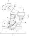
- pinch plate 56 Shown approximately vertical in the drawings is a pinch plate 56 that may be used to perform the web cut-off similar to the system shown in US 6056229 .
- While the drawings show the web W approaching the winding drum 50 generally vertically, the approach angle of the web to the winding drum 50 may be rightward or leftward of the generally vertical shown in the drawings.
- the pinch plate may be provided in a corresponding manner relative to the angle of approach of the web to the winding drum 50. Shown to the left and lower left of the winding drum are fingers 58 and a curved rolling surface 60 that may be used to guide a core 62 during web transfer and then guide the rolling log 64 to the winding region, similar to the system in US 6056229 .
- the winding log 64 After the winding log 64 has been brought into contact with the belt 52 it must be advanced further through the space between the winding drum 50 and the belt 52 toward the winding nest N. This may be referred to as log introduction or log progression. It is understood that this is a critical phase in the winding cycle for control because the log is advancing very rapidly and increasing in diameter very rapidly. If properly controlled, the winding log 64 will decelerate both rotationally and translationally as it advances toward the winding nest N and remain in contact with both the winding drum and the belt during this transition. To bring the log 64 forward into the winding nest N, the belt 52 has a lower surface speed than the surface speed of the winding drum 50.
- the belt surface speed may be operated faster so that the log does not skid through the nip, lose contact with the winding drum, and cease rotating.
- belt speed may be increased.
- belt speed and belt position relative to the winding drum may be changed as necessary based upon the application speed, size of the product, and desired firmness of the resultant log. Having the belt at a relatively fixed position relative to the winding drum may be more effective for tighter winding, which may be desired for certain firm and high firmness products.
- a second degree of freedom may be added to the belt 52 so that the distance between the belt 52 and winding drum 50 may be varied through the product cycle according to a profile that allows the log to progress into the winding nest N in a controlled fashion without being radially compressed or deformed by passing through a narrow nip point.
- the position profile of the belt 52 is calculated as a function of the delivered web, log diameter, log position, or any combination thereof.
- the position profile of the belt may be calculated to advance the log 64 in a controlled fashion wherein contact of the log 64 is maintained with the winding drum 50 and the belt 52.
- the log can be brought into contact with the belt farther from the narrowest point in the space S between the winding drum 50 and the belt 52 with greater control and without a tendency toward tight winding.
- the log advancement is controlled by the speed profile of the belt 52 and the position profile of the belt 52, which in combination afford greater control and winding quality for less firm and low firmness products.
- the start of the deceleration may be timed to cause a correct discharge of the finished or nearly finished log.
- the magnitude of the deceleration may be chosen to cause a correct introduction of the next log.
- the magnitude of the deceleration may be chosen to cause a correct discharge of the finished or nearly finished log and to cause a correct introduction of the next log.
- a control of the rewinder may establish a speed differential between the winding drum and the belt, which in turn controls the log progression through the nip between the winding drum and the belt.
- the surface speed of the belt may be at its lowest speed just before the arrival of the core/log so that the belt is increasing in speed when it is contacted by the core/log.
- the surface speed of the belt may be increased through the winding cycle as the growth of the log diameter and the geometry of the winding nest require a slower forward progression of the log.
- the surface speed of the belt may be relatively rapidly decreased near the end of the winding cycle, which in turn causes the log to start to advance more rapidly again for discharge.
- the control may store in memory a speed profile correlating belt speed over time, or belt speed versus wind cycle fraction, for the wind cycle.
- the belt speed profile may be executed as a position controlled motion.
- a speed profile may be executed as a position controlled motion by integrating a velocity profile.
- the belt speed profile may be preset (i.e., calculated and stored in a memory of the control of the rewinder) based on requested product parameters and then may be modified during the wind cycle, or between wind cycles, as needed.
- the belt speed profile may be preset for at least the intermediate phase of the winding cycle during which a preponderance of the log winding takes place.
- the belt speed profile may also be preset for the log introduction and/or log discharge phases.
- the belt speed profile may be calculated to account for log progression within the winding nest, increase of the log diameter during the winding, movement of the belt position, or any combination thereof.
- a calculated speed profile may be used that is based on the physics of the process to promote uniform winding, maximum diameter, and reduced vibration.
- Fig. 7 is a graph of an exemplary winding belt speed profile.
- Fig. 3 shows a rider roll 54 meeting an incoming log.
- Fig. 4 shows the rider roll 54 on the log during winding, at a position substantially equidistant from the winding drum 50 and belt 52.
- Figures 5 and 6 show the rider roll 54 at a higher positon on the log 64. The rider roll may be moved to a higher position to increase the space between the rider roll 54 and the belt 52 to allow a sufficient gap through which the discharging log can pass.
- the rider roll may have its surface speed increase during its upward movement around the log so its movement does not scuff or damage or wrinkle the log web wraps.
- the rider roll may have its surface speed increase at or near the end of the wind cycle to assist with accelerating the log for discharge. After the finished log 64 has moved clear of the rider roll 54 and the return path of the rider roll to the winding nest N, the rider roll may move down quickly to meet the next incoming log.
- the winding drum 50, belt 52, and the rider roll 54 provide three regions of contact at the log periphery for driving and controlling the winding log during the winding cycle.
- the rider roll speed profile and rider roll position motion profile may be calculated to account for log progression within the winding nest, increase of the log diameter during the winding, movement of the belt position, or any combination thereof.
- the discharge surface 68 may be provided downstream from the end of the belt 52.
- the discharge surface 68 may include a table that has a starting position just beyond the point where the belt starts to curve around the rotatable pulley 66. If multiple parallel belts are used, the table may include fingers that interdigitate with the spacings between parallel belts. The fingers may extend beyond the curved portions of the belts, so that the log 64 transitions more gradually from the surfaces of the belts to the fingers of the discharge table.
- the discharge table fingers may have coordinated motion with the belt positioning mechanism, so a constant relationship is maintained between the fingers and belts.
- the discharge table fingers may be positionable independent of the belts, for instance, to recede beneath the belts at a position farther upstream in the winding nest for smaller diameter products and farther downstream in the winding nest for larger diameter products.
- the fingers may be positioned in order to set a desired distance over which the logs roll on the belts as they discharge.
- a discharge gate, or other device known in the art, may be provided downstream of the winding nest to capture a finished wound log, and/or control the timing of the exit of the finished wound log from the rewinder.
- a winding nest comprising a winding drum and belt, for instance as shown in Figs. 1- 6 (and in other figures to be discussed later), forms a winding nest that is favorable to run low firmness and large diameter, low log firmness logs at high speeds with less vibration.
- the nip of the belt against the surface of a winding log has less potential to cause interlayer slip between the successive wraps of web within the rotating log than the nip of a drum against the surface of a winding log.
- a winding belt instead of a lower winding drum may significantly increase the area of the nip contact with the log, thereby reducing the nip pressure to reduce the interlayer slip.
- a low firmness log may have a concave indentation at its nips with the winding drums because low firmness logs can be readily deformed. This shape of indentation combined with the greater pressure of its smaller area of nip contact may penetrate deeper into the winding log and thus communicate with more layers of wrapped web, promoting interlayer slip.
- a low firmness log may have substantially flat, even possibly slightly convex, deformation. This shape of indentation may tend to penetrate less deep into the layers of wrapped web of the winding log and thereby reduce the interlayer slip.
- the geometry of the belt being flat, or slightly concave, with respect to the winding log, rather than convex as with a winding drum may tend to reduce interlayer slip.
- the nip of the belt against the surface of a winding log has more potential to retain the caliper, or thickness, of the web being wound in the rotating log.
- a winding belt instead of a drum may significantly increase the area of the nip contact with the log, and thereby reduce the nip pressure.
- Reduced nip pressure would reduce the tendency for the web material to thin by crushing the caliper or compressing the embossing.
- Retaining the thickness of the web material is advantageous when winding high bulk and low firmness products and low firmness large diameter products at higher speeds.
- the vibration energy may be absorbed or dispersed through the nip with the belt and may be spread over a larger contact area than would be the case with a winding drum, which may result in less tendency to produce an out of specification log.
- the substantially flat, even possibly slightly convex, deformation of the log at its nip with the belt 52 may provide other advantages and may be enhanced by varying the characteristics or adjustments of the belts.
- the material on the surface of the belt may be compliant, and thus conform under the load of the log, increasing its contact area, and reducing the contact pressure and deformation on the log.
- the belt itself may be stretchable or elastic, and may extend under the load of the log, wrapping the log slightly, increasing its contact area, and thereby reducing the contact pressure and deformation on the log.
- the tension setting in the belt may also be varied to influence the contact pressure and deformation on the log.
- the position of the belt under the winding log, where it bears a preponderance of the weight load of the log may be advantageous over other configurations of winding nests or other possible positions of a winding belt with respect to the log.
- the log In a surface rewinder winding nest, the log is supported at its periphery. In the case of a winding nest with just winding drums, the log weight load is supported by the drums, typically primarily a lower winding drum. In a winding nest with upper and lower winding drums, little can be done to cause a reduction of the pressure in the nip at the lower winding drum, because the weight of the log causes the pressure. However, given the shape of the belt 52 for reducing nip pressure, as described above, the same log weight may be supported with less nip pressure, as compared to a lower winding drum.
- positioning the belt under the log, where it may support a preponderance of the weight of the log may be especially beneficial for larger diameter, low firmness logs, which add weight load as they increase in size, and thus encounter rising nip forces through the wind cycle.
- a belt could be utilized on any side of the winding log, but under the log is the most effective location partly because the weight load of the log is unavoidable.
- winding low firmness logs in a 3-drum surface rewinder efforts can be made to reduce the nip pressures at the upper winding drum and the rider roll (though not as effectively as with a belt system, as is described in the next paragraphs of the disclosure), but little can be done about the weight of the log on the lower drum, and the nip there would typically have the greatest pressure, and its nip pressure would increase as the diameter of the log increases. So under the log is the most favorable position for the belt to alleviate a nip pressure.
- the arrangement may also be advantageous with processing of structured and/or textured webs (e.g., NTT, QRT, etc.), or specialized embossing in the web, during the wind cycle, because the lower contact pressure in the nip of the belt configuration compared to a configuration with a winding drum may tend to reduce thinning of the web material from crushing or compressing its structure or texture or its embossing.
- a reduced magnitude of radial deformation of the log in its nip with the belt, compared to a nip with a winding drum, may also induce less strain in the web wraps as they pass through the nip, which may help preserve the thickness of structured web and prevent elongation of the structured web. This in turn may reduce the potential for the structured web to reach a strain threshold beyond which a significant portion of the thickness of the structured web does not return to its nominal thickness when the tension load is removed or reduced.
- the belt 52 may be provided with a belt positioning mechanism ( Figs. 38-39 , '130') so the angle of the belt and the spacing S of the belt relative to the winding drum 50 and rider roll 54 may be adjusted in accordance for a particular log 64 product based upon web material properties, core diameter, and finished log diameter.
- the belt may be positioned as needed to minimize the contact pressure at the nip points between the winding drum and the log, the belt and the log, and the rider roll(s) and the log. This tends to be advantageous to maximize wound log diameter.
- the contact pressure between the winding drum 50 and the log 64, the belt 52 and the log, and the rider roll and the log may be increased or decreased by adjusting the general position of the belt with the belt positioning mechanism, or by adjusting the relative angle of the belt from generally horizontal to more or less inclined.
- the position of the belt during the winding cycle allows different diameter products to be wound with reduced or minimized or optimized nip pressure during the entire winding cycle.
- logs typically must climb upward on the lower winding drum as they enter the winding nest. Thus early in the winding cycle the log tends to "lean" against the upper drum and the nip pressure may be greater than desired.
- a winding nest comprising a winding drum and belt, for instance as shown in Figures 1- 6 (and in other figures to be discussed later), forms a winding nest that is favorable for improved control of the log during introduction into the winding nest N.
- the incoming log must be decelerated under good control through the space between the winding drum 50 and the belt 52 to be brought into the winding nest efficiently and reliably. It is believed that if the log deceleration is executed over a greater distance of log translation, then the acceleration magnitude may be reduced, which may in turn make the critical phase of log introduction to the winding nest better able to accommodate variations in the properties of the incoming web material, and machine operating conditions.
- a winding nest with a winding drum and a belt may be configured to have a translational distance sufficient for decelerating the log during introduction to the winding nest N.
- the surfaces of two opposing drums diverge more rapidly as an object passes through the space between them compared to the surfaces of a drum and an opposing belt if the belt surface is substantially a flat plane.
- the belt 52 may be of unitary construction, or consist of at least two portions: (i) a log contact side that engages the log, and (ii) a pulley contact side that engages a pulley that drives the belt.
- the log contact side of the belt may have a covering layer.
- the log contact side of the belt is preferably wear resistant and has a high traction and/or high grip characteristic.
- the log contact side of the belt may comprise a rubber or elastomer type of material with high grip characteristics.
- the log contact side of the belt may comprise a rough surface with high traction characteristics.
- the log contact side of the belt may be changed or modified to have more or less grip or traction.
- a covering layer of the belt may be softer or harder, thicker or thinner, more or less compliant, depending upon the application, to provide desired characteristics for the interaction of the belt and the winding log.
- Surface textures may be imposed or deployed on the log contact side of the belt by casting, imprinting, machining, laser engraving, implanting, etc. Protrusions or embossments may be utilized on the log contact side of the belt.
- a high traction and/or grip characteristic on the log contact side of the belt is preferable to afford control of the winding log at its nip with the belt in the introduction, winding, and discharge phases even with minimal or minimized or low contact pressure at the nip.
- the pulley contact side of the belt may have a high traction and/or high grip characteristic, to reduce or minimize or eliminate slipping of the belt on the drive pulley during its acceleration and deceleration phases of the cycle.
- the pulley contact side of the belt may have an array of teeth which engage grooves in the pulleys to reduce or minimize or eliminate slipping of the belt on the pulley during its acceleration and deceleration phases of the cycle.
- the belt may have internal cords, as is known in the art, to increase its resistance to changing in length, so it remains substantially at a constant length during operation, including during its acceleration and deceleration phases of the winding cycle.
- each belt in the plurality of belts may be about 100 mm wide or up to about 500 mm wide or wider with a spacing or gap of about 25 mm between the belts.
- the rolling surface 60 from the infeed fingers 58 to the belts may be a contiguous surface or may comprise discrete fingers with spacing between the fingers.
- the fingers 58 may terminate short of the belt surface, or may project past the belt surface and interdigitate with the gaps of the parallel and spaced apart belts.
- Each of the belts in the plurality of belts may be independently adjustable to accommodate any variation between the belts.
- a tensioner, movable third pulley, or sliding shoe may be used in connection with each belt to provide an adjustment to ensure proper tension.
- the plurality of belts may be driven with one pulley or each belt may have a dedicated pulley.
- a core end engagement assembly 80 may be provided to engage and, depending on the application, rotationally drive the core during the winding cycle.
- a core end engagement assembly 80 may be provided with a core chuck 82 to engage with one end of the core 62.
- a second core end engagement assembly axially opposite of the core 62 may also be provided.
- the second core end engagement assembly may also include a second chuck 82 to engage with the axially opposite end of the core 62.
- the chuck 82 may engage an end face of the core or inner diameter surface of the core or both.
- the core 62 may be rotationally driven by the chuck 82 of one or both of the core end engagement assemblies 80.
- the core end engagement assembly 80 may include a pneumatic, hydraulic, electronic or mechanical actuator 86 that allows the chucks 82 to reciprocate substantially in alignment with the core central axis for insertion into and withdrawal from the hollow ends of the core 62.
- the core end engagement assembly 80 may also have a pneumatic, hydraulic, electronic or mechanical actuator 88 that enables the chuck 82 to expand radially outward to engage the inner diameter surface of the core 62. For instance, as shown in Figs. 8 and 9 , the actuator 88 linearly moves a control rod 90 which in turn moves the chuck 82 between engaged and disengaged positions relative to the inner diameter surfaces of the core 62.
- the chucks 82 Prior to engaging the core 62, the chucks 82 may rotate to a speed matching the rotational speed of the core.
- a motor (not shown) coupled to a flexible drive shaft 96 may rotationally drive the chuck 82.
- the flexible drive shaft 96 may be coupled to the control rod 90 adjacent the actuator 88 at an axial end of the drive housing 94.
- the chucks 82 may rotate freely at the speed of the rotating log. Accordingly, the chucks may be idling chucks.
- the chucks 82 may also, or in the alternative, tend to impart a slight braking action against the log during at least part of the wind cycle.
- the braking action may be provided via a mechanical or magnetic clutch-type mechanism and/or via the motor.
- the chucks may be caused to rotate faster for at least part of the cycle, causing a log to wind tighter.
- the chucks may be caused to rotate slower for at least part of the cycle, causing a log to wind looser. Offsetting, scaling, stretching, and/or other manipulations of this profile may be used to produce a speed profile wherein the chucks rotate faster or slower for at least part of the cycle.
- the chuck position profile may be preset for at least the intermediate phase of the wind cycle during which a preponderance of the log winding takes place.
- the chuck position profile may also be preset for the return phase, wherein the chucks travel from their position at the end of winding a finished log to their position for engagement to the core of a subsequent log.
- the chuck position profile during the winding phase may be calculated to account for log progression within the winding nest, increase of the log diameter during the winding, movement of the belt position, or any combination thereof.
- the chuck position profile may substantially match the positions that theory suggests the winding core should have for the case of a circular log.
- the observations, measurements, feedback, and data may include, and are not limited to, caliper of the incoming web material, machine direction tensile modulus of the incoming web material, z-direction modulus of the incoming web material, tension and changes in tension of the incoming web material, the diameter and/or firmness of wound logs, vibration of logs during winding, caliper of web measured in finished logs, comparison of measured properties in the web before winding and after winding, and comparison of a measured web caliper value to a calculated web caliper value for a roll.
- the calculated average caliper for a wound roll product may be obtained with the following equation, where the area of the cross-section of a roll is divided by the length of the web material wound into the roll.
- Figs. 10-16A and 16B show another embodiment of a winding nest configuration. It is similar in layout and function to that shown in Figures 1-6 so the same reference characters are used to identify like components.
- the rider rolls 54A,54B may use the same positioning mechanism, and such a positioning mechanism may provide compound motion, arcuate motion, linear reciprocating motion or any combination thereof.
- a separate positioning mechanism 70,72 for each rider roll may be provided.
- the rider roll 54A may have simple arcuate motion centered about the center of the winding drum 50 with its positioning system 72, and the rider roll 54B may have compound motion with its own dedicated positioning mechanism 70.
- the rider roll 54A closer to the winding drum 50 may engage incoming log 64 first. As the log 64 increases in diameter during the winding cycle, the rider roll 54A may travel toward the top of the winding log 64, making space for the rider roll 54B to engage the log 64 at the side of the log (per the drawings). For very small diameter logs, the system may be configured to use only one of the rider rolls, where there may not be space available to have both rider rolls 54A,54B engaged during a majority of the winding cycle. As shown in Figure 12 , the rider roll 54A only may be used. Alternatively, for instance, as shown in Fig.
- the rider roll 54A may be parked out of the way and the rider roll 54B only may be used, if there is adequate clearance and the compound motion positioning mechanism of the rider roll 54B has adequate downward travel to engage a small diameter log 64.
- Figure 11 shows the rider roll 54A meeting an incoming log.
- Figure 12 shows the rider roll 54A having migrated to near the top of a winding log 64, and there is now space for the rider roll 54B to approach the side of the log as shown in Figure 13 .
- Figures 13 - 14 show the rider roll 54B in contact with the log 64, at a position substantially equidistant from the rider roll 54A and the belt 52. Operation of the rider rolls at log discharge may depend on the relative diameter of the finished log, as described below:
- the rider roll 54A may be moved away from the winding log 64 to make space for the rider roll 54B to orbit higher to a more preferred position for log discharge (see Figure 22 ).
- the rider roll 54A initiates log discharge in conjunction with the belt.
- the rider roll 54B may track with the log, and remain in contact with the log for the most part during discharge, and assist with log discharge.
- Contact of the rider roll 54B with the log 64 need not be continuous during discharge because the log already has translational momentum, and the discharge is also controlled by speed reduction of the belt 52.
- the presence of the rider roll 54B above the log 64 ensures the discharge is completed and also serves to contain and direct a log that may be vibrating at the start of its discharge.
- the rider roll 54A may initiate its return to meet a subsequent log as the rider roll 54B moves out of its path.
- An example of this log discharge is shown in Figures 22-24 .
- the winding nest N utilizes three contact regions spaced evenly about the log from early in the wind cycle, followed by four contact regions well-spaced about the log for a preponderance of the winding cycle when vibration of the log is most likely to occur, followed by three regions of contact well-spaced about the log at the start of log discharge. Having four contact regions at the log periphery, which drive the log in rotation and spatially contain the log, is favorable for winding low firmness and low firmness large diameter logs at higher speeds without excessive vibration, or with less vibration.
- the reduced contact pressure on the log at the nips may further reduce the compression, tension and/or elongation of the wraps of web material that tend to distort or thin a structured web or embossing.
- a core chuck 82 or core chucks as described previously may be provided in the winding nest configuration shown in Figures 10-24 .
- Figure 12 shows the rider roll 54A having migrated to near the top of a winding log 64, allowing space for the rider roll 54B to approach the side of the log, as shown in Figure 13.
- Figure 13 shows the rider roll 54B in contact with the log 64, at a position substantially equidistant from the rider roll 54A and the belt 52.
- the gap may be formed after the rider roll 54A has moved toward the top of the winding log 64 far enough that the log can be translated away from contact with the winding drum 50 under good control, for instance as shown in Figure 14 .
- the surface speed of the belt may be reduced to cause the log to move away from the winding drum 50.
- the rider rolls 54A,54B may assist with controlling the movement of the log 64 away from the winding drum 50.
- the core chucks 82 may also be engaged and rotationally driving the core 64, and may assist with controlling the movement of the log away from the winding drum.
- Figures 25-30 show winding a log in the winding nest with two rider rolls and the belt and a gap G between the log 64 and the winding drum 50. When the winding of the log 64 is nearly complete, the rider roll 54B may orbit to near the top of the log, providing space for the log to discharge.
- Figure 30 shows the rider roll 54B having orbited upward to make space for the log discharge, as described previously.
- a core chuck or core chucks as described previously may be provided in the winding nest configuration shown in Figures 25 - 30 .
- Figures 31-37 show an alternate embodiment of a winding nest configuration similar to that of Figures 10-24 and Figures 25-30 where the motions of the winding drum 50, two rider rolls 54A,54B and the belt 52 are controlled to produce a small gap between the winding drum 50 and the log 64, and the rewinder control may monitor and enable changes in the amount of the gap during the winding cycle as may be desired to optimize the product and process.
- An objective of monitoring and changing the amount of the gap in the winding configuration of Figs. 31-37 is to minimize the contact pressure in the nip between the winding drum 50 and the log 64.
- a small gap may provide at least partial benefits of having a gap, as described previously, and yet provide at least partial benefits of having four contact nips, as described previously, because the gap is relatively small.
- the presence and/or size of a gap at this nip may be discerned by visual observation and/or sensor feedback.
- the sensor feedback may include photo-electric emitters and detectors and/or computer vision systems or other suitable devices.
- Modification of the motions may be made by an operator and/or the rewinder control system.
- the motions may be adjusted to optimize the product and/or process.
- the motions may be adjusted to reduce the gap. If the gap is absent, the motions may be adjusted to create a gap. If the gap is too small, the motions may be adjusted to increase the gap. The motions may be adjusted so the gap is small and intermittent. In this way, the contact pressure between the log 64 and the winding drum 50 may be reduced or minimized or eliminated, and yet retain the advantages of winding with four regions of contact to some degree.
- the motions of the belt 52 and the rider rolls 54A,54B may be controlled to cause a gap between the winding drum 50 and the log 64 having a target dimension of 2 mm.
- a feedback loop associated with the control system may be enabled to sense whether a gap was created at this interface and measure its size. Though a gap may briefly form between the log 64, and the winding drum 50, the log may wind less tightly due to the reduced or eliminated pressure at its interface with the winding drum, and thus have relatively increased diameter and thereby rapidly or immediately fill this gap and resume contact with the winding drum.
- the feedback loop would sense the gap has closed.
- the control system may then, optionally, modify the motion profiles again to another target gap dimension or larger target gap dimension, possibly resulting in an even larger diameter log.
- the feedback of log diameter may be used to control the gap.
- motions may be controlled to maintain the condition of no gap, intermittent gap, or an approximate size of a gap, when the desired log diameter is achieved.
- Motions may also be controlled to create a gap, create an intermittent gap, or increase the size of a gap, when the log diameter is too small.
- Motions may be controlled to eliminate a gap, eliminate an intermittent gap, or reduce the size of a gap, when the desired log diameter is too large.
- Motions may be controlled to eliminate a gap, eliminate an intermittent gap, or reduce the size of a gap, based on the level of the log vibration.
- one or both rider rolls may be controlled to have greater or less surface speed or positioned to provide greater or reduced pressure on the log, and/or the belt may be controlled to have greater or less surface speed.
- the gap may also close at least intermittently with log vibration. In this condition, the close proximity of the winding drum 50 to the log 64 serves to offer a fourth region of contact for log containment.
- the gap feedback may be used to adjust upstream processes such as embossing or calendaring, or web speed.
- the beginning part of the winding cycle may be like the beginning of the winding cycle for the winding nest configurations of Figures 10-24 and Figures 25-30 .
- Figure 11 shows the rider roll 54A meeting an incoming log.
- Figure 12 shows the rider roll 54A migrated to near the top of a winding log 64, allowing a space for the rider roll 54B to approach the side of the log.
- Figure 13 shows the rider roll 54B in contact with the log 64, at a position substantially equidistant from the rider roll 54A and the belt 52.
- the gap may be formed after the rider roll 54A has moved toward the top of the winding log 64 far enough that the log can be translated away from contact with the winding drum 50 under good control.
- the surface speed of the belt may be reduced to cause the log to move away from the winding drum 50.
- the rider rolls 54A,54B may assist with controlling the movement of the log 64 away from the winding drum 50.
- the core chucks 82 may also be engaged and rotationally driving the core 64, and may assist with controlling the movement of the log away from the winding drum.
- Figures 31-37 show winding a log in the winding nest with two rider rolls and the belt and a small gap SG between the log 64 and the winding drum 50. When the winding of the log 64 is nearly complete, the rider rolls 54A,54B and belt 52 may cooperate to cause discharge of the log from the winding nest as described previously.
- a core chuck or core chucks 82 as described previously may be provided in the winding nest configuration shown in Figures 31 - 37 .
- FIG. 1 Another alternate embodiment is a winding nest comprising a winding drum 50 and a belt 52 as shown and described in connection with Figures 1- 6 , but with the rider roll 54 omitted.
- the winding core and web would pass into the winding area N as with the other embodiments, with its introduction controlled by the winding drum 50 and speed profile of the belt 52.
- the speed profile of the belt comprises a cyclic reduction and increase of the speed, as described previously.
- the belt 52 may also have its position varied with respect to the winding drum to further control the log progression, as described previously. In various cases, for example winding relatively firm logs, or at reduced winding speeds, or of narrower web widths, or a combination thereof, control of the log by the winding drum 50 and belt 52 may be sufficient.
- the belt speed may be increased, or elevated, which tends to wind the log tighter, and also tends to increase the contact pressure of the log against the winding drum, which affords further control of the log.
- the belt 52 may decrease in speed, causing the log to move away from the winding drum 50 for discharge, as previously described.
- the surface of the belt may have a slight incline downward toward the log discharge direction, which may assist with log discharge.
- An advantage of this embodiment is the reduced cost of having no rider roll(s). As was described above, it may be effective and economical at winding relatively firm logs, or at reduced winding speeds, or of narrower web widths. It may be useful especially in winding products which are often converted in narrower web widths.
- a core chuck or core chucks as described previously may be provided in this winding nest configuration.
- the core chuck or chucks may engage the winding log after it has come into contact with the belt and is being driven in rotation by the winding drum and the belt.
- the rotational speed and position of the core chucks may assist with control of the winding of the log.
- the rotational speed and/or position of the core chucks may assist with log discharge. Near or at the end of the winding cycle the chucks may increase in rotational speed to assist with log discharge. Near or at the end of the winding cycle the chucks may translate with the log to assist with log discharge.
- Figure 38 shows a schematic side view of an embodiment of a rewind system 100 which may use a winding nest configuration as described previously in this specification and include other components forming a path for the web material W to be wound. It may include a web spreading roller 102. It may include upper web feeding and guiding rollers 104, also referred to as upper draw rolls. Disposed downstream therefrom, the rewinder may be provided with a perforating unit 106. The perforating unit 106 may be configured to produce perforation lines in the web material W, which make the web weaker at localized points where it may be separated by the rewinder for web transfer or may be separated by the end user into individual sections or sheets, or both.
- Perforating roll member 108 may be provided with stationary cutting knives or blades for the perforating function.
- Perforating roll member 110 may be provided with one or more rotating knives or blades for the perforating function.
- Noncontact perforation devices known by those skilled in the art may also be used.
- the rewinder Downstream of the perforating unit 106, the rewinder may be provided with lower web feeding and guiding rollers 112, also known as lower draw rolls. The lower draw rolls 112 may direct the web W to the rewinder apparatus 120.
- the relative speeds of the draw rolls 104,112 and the rewinder apparatus 120 may be changed with respect to each other, and with respect to other upstream equipment (not shown), to alter the tension in the web material W to be higher or lower, or optimized.
- the speed relationship between the upper and lower draw rolls 104,112 may be altered to modify or optimize the web tension through the perforating unit 106, and the speed relationship between the lower draw rolls 112 and the rewinder apparatus 120 may be altered to modify or optimize the web tension into the rewinder apparatus 120.
- Altering the speed relationship may be used to increase or decrease the web tension.
- Altering the speed relationship may be used to maintain or substantially maintain the web tension, for instance, in response to a disruption, such as when the web is severed or when the web is transferred to a core to initiate winding a log, or a change in the web material properties, such as a change in the elastic modulus of the web material.
- These speed relationships may be set to reduce or minimize or substantially eliminate the web tension, especially the web tension into the rewinder apparatus 120. Very low, and even substantially zero, web winding tension is favorable for winding high bulk logs and low firmness logs and low firmness logs of large diameter, and to maximize the diameter of log which can be wound from a certain length of web material. These speed relationships may be altered manually or automatically, based on observation or feedback signals, or according to a pre-defined profile the executes cyclically with the log winding cycle.
- US 6,056,229 and US 6,422,501 disclose a web severing and transfer apparatus which may be incorporated herein.
- a stationary pinch plate 56 may be provided on the same side of the web as the winding drum, in close proximity to the web.
- the core inserter rotates clockwise so the pinch pads disposed on it may approach the stationary pinch plate and the winding core disposed on it may approach the infeed fingers 58.
- the core inserter motion may be timed and phased to pinch the web against the stationary plate when the perforation is just downstream of the core, so in very rapid succession an abrupt tension rise severs the perforation and the core is pressed against the web between it and the winding drum and starts to rotate.
- the longitudinal strip of transfer glue may cause the leading edge of the web to adhere to the core and thus start winding of the log 64.
- the belt 52 may be supported by upstream and downstream pulleys 66A,66B.
- the belt 52 may be driven to have a surface velocity by the downstream pulley and a motor 125 coupled thereto.
- a pulley 66C may be provided in the portion of the belt loop opposite the log contact portion of the loop.
- the pulley 66C may be movable to facilitate setting the tension in the belt.
- the pulley 66C may be moveable to facilitate mounting and/or dismounting a belt 52.
- the belt 52 may have a support 126 inside the belt loop that may operate against its inside surface in the portion of the belt loop that contacts the log 64. This support surface 126 is preferably flat.
- the support surface may also be slightly concave or convex.
- Exemplary low friction materials are plastics, acetal, nylon, and the like.
- the upstream and downstream ends of the support surface 126 may have chamfers and/or radii along their edges to facilitate smooth transfer of the belt or belt teeth onto and off of the support surface.
- a structure 128 to support the pulleys 66A,66C rotatably mounted in bearings and the belt support surface 126.
- the support 128 may comprise a beam element that extends substantially for the width of the belt(s) 52.
- the structure 128 may be supported from a beam outside the loop at or near its ends and optionally at intermediate points, or an intermediate point, as well. Utilizing an intermediate support or intermediate supports may allow the structure 128 to be sized smaller and with less mass, which is favorable for rapid motions.
- cyclically moving the belt surface 52 farther from and closer to the winding drum 50 during the introduction and winding of the log may be accomplished by a belt positioning apparatus 130, which may comprise pivots, linkages, or a slide, or a combination thereof.
- the belt positioning apparatus 130 includes pivoting motion driven by a motor 132 and linkages.
- the belt 52 may pivoted about the downstream pulley 66B, which may also be the drive pulley for the belt 52.
- the downstream pulley 66B may be comprised of a single pulley.
- the downstream pulley may be comprised of at least two adjacent coaxial pulleys, with at least one intermediate bearing support between them.
- Also arranged on the beam 134 may be a pivot with a crank arm to control a four-bar linkage which is connected near the upstream end of the belt 52, which may be used to raise and lower the upstream end of the belt.
- the coupler of this four-bar linkage may connect at the axis of the upstream pulley 66A.
- a crank arm and 4-bar linkage may be disposed at each end of the belt system and at at least one intermediate support. The crank arms on the pivot are controlled by a motor with position feedback to execute the motion profile of the belt position for the log introduction and winding.
- the discharge surface 68 may be supported from the same beam 134, to facilitate retaining a correct relationship between the discharge surface 68 and the belt 52 when the belt height is adjusted. It is preferable that the exit height of the log from the rewinder is constant, so a fixed height rolling surface may be provided downstream from the adjustable height discharge surface, with fingers on its upstream side interdigitate with fingers on the downstream side of the discharge surface 68 to ensure a reliable log transition.
- a discharge gate 136 may be provided above the discharge surface 68 to capture a finished wound log and/or control the timing of the exit of the finished wound log from the rewinder apparatus 120.
- the rider roll positioning system 72 has geometry that develops an arc motion for the rider roll 54A with the center point of its arc coincident with the central axis of the winding drum 50. This is accomplished by using a four-bar linkage with parallel crank and follower links of common length. All points on the coupler execute an arc motion.
- the upper pivot may have crank arms controlled by a motor with position feedback to execute the motion profile of the rider roll position.
- the lower pivot may have follower links supported in simple bearing or bushing joints.
- a motor with its axis of rotation mounted coincident to the upper pivot may be used to control the rider roll positon.
- FIG 10 illustrates a positioning system 70 which may be used for the rider roll 54B.
- the positioning system 70 allows for compound motion, which is a 2 degree-of-freedom device capable of arc motion, linear motion, or any combination thereof. This is accomplished by having motor controlled crank arms at the lower left pivot and motor controlled crank arms at the upper right pivot. Together the motors control the position of the rider roll 54B and can move it through the winding nest according to any motion path.
- the crank arms at both pivots are controlled by motors with position feedback to execute the motion profile of the rider roll position.
- the motors used to control the rider roll position may be mounted with their axes of rotation coincident to the lower left pivot and upper right pivot.
- the rotational drive for the rider roll 54B may comprise timing belts operating on pulleys which are mounted adjacent to and coaxial with the linkage joints.
- the timing belt drive may extend in sequence back to a motor with its axis of rotation mounted coincident to the lower left pivot, or near the lower left pivot.
- the rotational drive for the core chuck may comprise timing belts operating on pulleys which are mounted adjacent to and coaxial with the linkage joints.
- the timing belt drive may extend in sequence back to a motor with its axis of rotation mounted coincident to the lower pivot or the upper pivot, or near one of these pivots.
- the rotational drive train for the core end engagement assembly 80 have a relatively low level of inertia. It can be appreciated that the core chucks must rotate at very high speed at the beginning of the winding cycle and when they engage the core. Speeds of 5,000 - 8,000 rev/min and greater may be contemplated. For example, the rotational speed of a log with 38 mm diameter and 800 m/min surface speed is approximately 6,700 rev/min.
- the core chuck may be operated at greater rotational speed than the log before it engages the core in the log so that it may have matched velocity and matched rate of change in velocity (acceleration), and conceivably also matched rate of change in acceleration, so as to cause minimal disruption to the log and core when it is engaged to the core.
- the rotational speed of a log with 130 mm diameter and 800 m/min surface speed is approximately 1,960 rev/min.
- the rotational speed of a log with 200 mm diameter and 800 m/min surface speed is approximately 1,270 rpm.
- the linear actuator 86 may be used to shift the assembly translationally along its axis, inwardly toward the core of the log and outwardly away from the core of the log.
- the second linear actuator 88 may be disposed near the rear of the assembly, and its rod end may be connected to the drive housing 94 with a first arm 146.
- a second arm 148 may connect the body of the second linear actuator 88 to the control rod 90 through a thrust bearing 150 which allows relative rotation between the control rod 94 and the second arm 148, but causes the control rod 90 and the second arm 148 to move axially together.
- the second linear actuator 88 moves the control rod 90 (leftward in the drawings) axially within the drive housing 94 and support shaft 92.
- the body of the chuck 82 comprises elastomer rings, which may be disposed on the distal end of the control rod 90. When the elastomer rings are compressed axially they expand radially and may engage the inside surface of a core with surface pressure. A single elastomer ring may be used on the chuck body.
- the frame arm of the core chuck positioning system 84 may be moved to align the chuck body with the end of the core 62.
- the first linear actuator 86 may retract to slide the drive housing 94 axially to insert the chuck body into the core end.
- the second linear actuator 88 may extend to axially move control rod 90 to engage the core (leftward in the drawings).
- the support shaft 92 is axially restrained so the annular elastic pieces are compressed axially and expand radially to engage the inside surface of the core.
- Figure 9 illustrates in cross-section the core chuck of Figure 8 inside a core and radially expanded to engage the core.
- the first linear actuator 86 may be commanded to extend, which will cause a tension force in the core, as described previously.
- a third linear actuator (not shown) may be used, positioned in series with the first linear actuator 86, to produce the tension force in the core.
- the actuation motion to induce a tension force in the core may be executed at just one end of the core. This means that after both core chucks have engaged the core, one of them may be held axially fixed and the other may be moved axially to cause the tension force in the core so that the core does not drift axially in the machine or in the log during winding.
- the tension force that was induced in the core may be relieved by causing the linear actuator 86 to cease pulling on the core, the core chucks may be disengaged from the core ends by causing the linear actuator 88 to retract the control rod 90 (move rightward in the drawings) to contract the annular elastic pieces, and the linear actuator 86 may shift the assembly leftward to withdraw the core chuck from the core.
- the rotational speed of the chucks may be adjusted to match the speed required for engagement with the core in the next log as the core chuck positioning motors move the assembly to the center of the next log.
- the flexible shaft 96 may undergo changes in its curvature to accommodate the axial and spatial movements of the assembly as the core chucks are inserted into cores, as the core chucks track with the centers of winding logs, as the core chucks are withdrawn from the cores, and as the core chucks travel to align with the center of a subsequent log. Changes to the curvature of the flexible shaft may accommodate the axial movement of the control rod 90 when the assembly is shifted axially to insert or remove the chuck from a core.
- the flexible shaft may also accommodate the axial movement of the control rod 90 when second linear actuator 88 shifts axially to expand or contract the chuck, and movement of the control rod 90 through space by the core chuck positioning motors.
- the flexible drive shaft may accommodate three translational degrees of freedom in addition to the rotational degree of freedom utilized to drive the chuck 82.
- Figures 8 and 9 show the linear actuators 86,88 as pneumatic cylinders.
- actuators may be used for this function.
- An advantageous example is a linear induction motor.
- a particularly advantageous example is a linear induction motor with position and force feedback which may be operated under position control, or force control, or both.
- the core chuck may be inserted very quickly and smoothly with a programmed motion profile.
- the actuator may very quickly switch to applying a controlled tension force to the core during the winding.
- the actuator may relieve this tension force extremely quickly when it is time to disengage the core, and then withdraw the core chuck very quickly and smoothly with a programmed motion profile.
- a servo pneumatic system which uses position and air pressure feedback to control the linear actuator may be employed.
- Figures 8 and 9 show core chucks 82 which engage the core ends by expanding elastomer rings radially due to axial compression.
- the chucks may comprise annular bladders which expand radially when inflated by air pressure to engage the inside surface of the core, as is known in the art.
- the chucks may comprise mechanical elements which expand radially under the urging of push rods, cams, wedges, or the like, to engage the inside surface of the core.
- Figure 38 shows a sprayer 160 disposed upstream of the winding nest in proximity to the web.
- the sprayer 160 may be a spray nozzle, or more preferably a plurality of spray nozzles.
- Spray nozzles or spray guns may be provided upstream of the winding nest to spray a liquid, or fluid, or mist, atomized dispersion, or the like of an agent on the web before it is wound into the log.
- the nozzles of the sprayer are preferably on the side of the web opposite the stationary pinch plate 56 and the winding drum 50, and preferably downstream of the lower draw rolls 112.
- Applying the agent to a web surface which will not pass over any rollers before being wound into the log may be favorable to keep the agent from depositing on the rollers and being wasted or fouling the rollers.
- Applying the agent to a web surface which is opposite the stationary pinch plate 56 may afford support to the web span by the pinch plate to minimize disturbance from the air flow or flow of the agent to the web.
- Such an agent as adhesive, or starch, or binder, or the like may be applied to the web and used to bond the initial layers of wrapped web in the log to each other.
- the bonding may be very light or strong by varying the chemistry and amount of the agent applied.
- the bonding may be temporary, so that the layers can be dispensed by unwinding from the roll and preferably used.
- Bonding the initial layers of wrapped web to each other can be advantageous for strengthening or stiffening or making more durable the hole of a coreless product, which may be produced in the rewinder embodiments illustrated in the figures of this specification with a removable mandrel.
- the agent may also be used to keep the central opening in the final roll product from collapsing.
- the agent may be water with minimal or no adhesive. Application of water, even without adhesive, may be used to attach layers of wrapped tissue, towel, and paper webs to each other in the log, through the formation and/or reformation of hydrogen bonds, or by activating bonding agents that are present in the web material.
Landscapes
- Winding Of Webs (AREA)
- Replacement Of Web Rolls (AREA)
- Storage Of Web-Like Or Filamentary Materials (AREA)
- Unwinding Webs (AREA)
- Treatment Of Fiber Materials (AREA)
Applications Claiming Priority (3)
| Application Number | Priority Date | Filing Date | Title |
|---|---|---|---|
| US201762592103P | 2017-11-29 | 2017-11-29 | |
| EP18883038.4A EP3717387B1 (en) | 2017-11-29 | 2018-11-26 | Surface rewinder with center assist and belt and winding drum forming a winding nest |
| PCT/US2018/062462 WO2019108480A1 (en) | 2017-11-29 | 2018-11-26 | Surface rewinder with center assist and belt and winding drum forming a winding nest |
Related Parent Applications (2)
| Application Number | Title | Priority Date | Filing Date |
|---|---|---|---|
| EP18883038.4A Division EP3717387B1 (en) | 2017-11-29 | 2018-11-26 | Surface rewinder with center assist and belt and winding drum forming a winding nest |
| EP18883038.4A Division-Into EP3717387B1 (en) | 2017-11-29 | 2018-11-26 | Surface rewinder with center assist and belt and winding drum forming a winding nest |
Publications (3)
| Publication Number | Publication Date |
|---|---|
| EP4116245A1 EP4116245A1 (en) | 2023-01-11 |
| EP4116245B1 true EP4116245B1 (en) | 2025-06-25 |
| EP4116245C0 EP4116245C0 (en) | 2025-06-25 |
Family
ID=66634290
Family Applications (4)
| Application Number | Title | Priority Date | Filing Date |
|---|---|---|---|
| EP22189396.9A Active EP4116245B1 (en) | 2017-11-29 | 2018-11-26 | Surface rewinder with center assist and belt and winding drum forming a winding nest |
| EP18883038.4A Active EP3717387B1 (en) | 2017-11-29 | 2018-11-26 | Surface rewinder with center assist and belt and winding drum forming a winding nest |
| EP19889086.5A Active EP3887297B1 (en) | 2017-11-29 | 2019-05-20 | Flexible drive and core engagement members for a rewinding machine |
| EP24174778.1A Pending EP4431424A1 (en) | 2017-11-29 | 2019-05-20 | Flexible drive and core engagement members for a rewinding machine |
Family Applications After (3)
| Application Number | Title | Priority Date | Filing Date |
|---|---|---|---|
| EP18883038.4A Active EP3717387B1 (en) | 2017-11-29 | 2018-11-26 | Surface rewinder with center assist and belt and winding drum forming a winding nest |
| EP19889086.5A Active EP3887297B1 (en) | 2017-11-29 | 2019-05-20 | Flexible drive and core engagement members for a rewinding machine |
| EP24174778.1A Pending EP4431424A1 (en) | 2017-11-29 | 2019-05-20 | Flexible drive and core engagement members for a rewinding machine |
Country Status (13)
| Country | Link |
|---|---|
| US (3) | US11046540B2 (enExample) |
| EP (4) | EP4116245B1 (enExample) |
| JP (2) | JP7234234B2 (enExample) |
| CA (2) | CA3082486C (enExample) |
| CL (1) | CL2021001169A1 (enExample) |
| CO (1) | CO2021006813A2 (enExample) |
| ES (1) | ES2940654T3 (enExample) |
| FI (1) | FI3717387T3 (enExample) |
| HU (1) | HUE061486T2 (enExample) |
| MX (3) | MX2020005199A (enExample) |
| PL (1) | PL3717387T3 (enExample) |
| PT (1) | PT3717387T (enExample) |
| WO (2) | WO2019108480A1 (enExample) |
Families Citing this family (13)
| Publication number | Priority date | Publication date | Assignee | Title |
|---|---|---|---|---|
| SE539767C2 (en) * | 2016-05-04 | 2017-11-21 | Valmet Oy | An apparatus for winding a web of paper material and a method of removing dust |
| WO2019108480A1 (en) | 2017-11-29 | 2019-06-06 | Paper Converting Machine Company | Surface rewinder with center assist and belt and winding drum forming a winding nest |
| JP6701584B2 (ja) * | 2018-09-28 | 2020-05-27 | 株式会社リコー | 給送装置、画像形成装置及び画像形成システム |
| US11247863B2 (en) | 2018-11-27 | 2022-02-15 | Paper Converting Machine Company | Flexible drive and core engagement members for a rewinding machine |
| US11383946B2 (en) | 2019-05-13 | 2022-07-12 | Paper Converting Machine Company | Solid roll product formed from surface rewinder with belt and winding drum forming a winding nest |
| GB2590372B (en) * | 2019-12-11 | 2022-02-09 | Dyson Technology Ltd | A drum for reeling sheet material |
| CN112248463A (zh) * | 2020-09-27 | 2021-01-22 | 嘉兴骏升机械股份有限公司 | 海绵工程用虹吸排水板三辊复合无纺布系统 |
| IT202100028685A1 (it) * | 2021-11-11 | 2023-05-11 | Futura Spa | Macchina ribobinatrice per la produzione di logs. |
| CN114933186B (zh) * | 2022-04-12 | 2025-06-17 | 湖南中南智能装备有限公司 | 一种防水卷材自动收卷装置及方法 |
| CN114872293A (zh) * | 2022-05-24 | 2022-08-09 | 安徽理工大学 | 一种eva塑料薄膜挤出机 |
| US20240158194A1 (en) | 2022-11-10 | 2024-05-16 | Paper Converting Machine Company | Method and Apparatus for Producing Coreless Roll Products |
| WO2025110987A1 (en) | 2023-11-20 | 2025-05-30 | Bw Converting, Inc. | Clasp for producing coreless roll products |
| EP4628438A1 (en) * | 2024-04-03 | 2025-10-08 | United Converting Tissue S.r.l. | Method and apparatus for the production of coreless paper rolls |
Family Cites Families (96)
| Publication number | Priority date | Publication date | Assignee | Title |
|---|---|---|---|---|
| US1437398A (en) | 1916-12-09 | 1922-12-05 | Cameron Machine Co | Rewinding device |
| US2090130A (en) | 1931-05-18 | 1937-08-17 | John J Kittel | Slitting and winding machine |
| US2385692A (en) | 1942-04-07 | 1945-09-25 | Scott Paper Co | Continuous winding machine |
| US2749133A (en) | 1954-08-16 | 1956-06-05 | James C Rich | Core chuck |
| US2883121A (en) | 1955-10-24 | 1959-04-21 | Hudson Sharp Machine Co | Endless conveyor having web rewinder core shafts |
| US3148843A (en) | 1959-10-09 | 1964-09-15 | Fmc Corp | Breaker bar for web rewinding machine |
| US3097808A (en) | 1961-08-21 | 1963-07-16 | Charles R Tidland | Expansion chuck |
| DE1774101B1 (de) | 1968-04-08 | 1971-11-04 | Weser Lenze Stahlkontor | Vorrichtung zum rollenwechsel und querschneiden von mit hoher geschwindigkeit laufenden bahnen bei mehrfach wickel maschinen |
| US3610545A (en) * | 1969-01-17 | 1971-10-05 | Reifenhauser Kg Maschinenfabri | Apparatus for winding continuously produced layer material on elongated core |
| US3676933A (en) * | 1969-10-09 | 1972-07-18 | Procter & Gamble | Continuous thickness measurement of a moving plastic web |
| DE2118963C3 (de) | 1971-04-20 | 1974-01-17 | A. Ahlstroem Oy, Helsinki | Verfahren und Vorrichtung zum kontinuierlichen Aufwickeln von Materialbahnen in Einzelrollen und Vorrichtung zur Durchführung des Verfahrens |
| US3704835A (en) | 1971-07-13 | 1972-12-05 | Arthur E Harley | Roll changing system |
| US3791602A (en) | 1972-03-13 | 1974-02-12 | Kimberly Clark Co | Roll rewinder transfer apparatus and method |
| BE795742A (fr) | 1972-10-12 | 1973-06-18 | Paper Converting Machine Co | Machine et procede de bobinage |
| JPS52109079A (en) * | 1976-03-09 | 1977-09-12 | Toray Ind Inc | Bobbin holding device for winder |
| JPS6033738B2 (ja) * | 1978-03-23 | 1985-08-05 | 川之江造機株式会社 | 紙の巻取装置 |
| IT1165998B (it) * | 1979-09-21 | 1987-04-29 | Fabio Perini | Dispositivo avvolgitore continuo per nastri di carta ed altro nella produzione di carta igienica e manufatti analoghi |
| IT1167967B (it) | 1981-08-26 | 1987-05-20 | Fabio Perini | Ribobinatrice ad alta velocita' per nastri di carta in specie con perforazioni trasversali |
| US4520704A (en) * | 1983-08-05 | 1985-06-04 | Beloit Corporation | Motor driven slitter of narrow configuration |
| IT1171233B (it) | 1983-09-27 | 1987-06-10 | Mira Lanza Spa | Macchina bobinatrice per l avvolgimento di nastri di carta su anime di cartone o simili |
| US4723724A (en) | 1985-04-17 | 1988-02-09 | Paper Converting Machine | Web winding machine and method |
| US4962897A (en) | 1986-04-01 | 1990-10-16 | Paper Converting Machine Company | Web winding machine and method |
| US4856725A (en) * | 1986-04-01 | 1989-08-15 | Paper Converting Machine Company | Web winding machine and method |
| FI81551C (fi) * | 1987-05-20 | 1990-11-12 | Valmet Paper Machinery Inc | Foerfarande och anordning vid rullningen av en bana. |
| DE3729358C2 (de) * | 1987-09-02 | 1993-12-02 | Windmoeller & Hoelscher | Spanndorn |
| US5267703A (en) | 1988-01-29 | 1993-12-07 | Fabio Perini S.P.A. | Apparatus for controlling the production of paper rolls produced by the rewinder in order to ensure steadiness of length of the wound paper and/or of reached diameter |
| IT1230585B (it) | 1988-10-21 | 1991-10-28 | Alberto Consani S P A D | Ribobinatrice funzionante a velocita' costante e relativo dispositivo tagliante. |
| IT1230935B (it) | 1989-06-27 | 1991-11-08 | Consani Alberto Spa | Dispositivo per l'alimentazione delle anime al gruppo di avvolgimento di bobinatrici o ribobinatrici |
| IT1233708B (it) | 1989-07-11 | 1992-04-14 | Perini Navi Spa | Macchina ribobinatrice per la formazione di rotoli o bastoni, e metodo di avvolgimento |
| JPH04317946A (ja) * | 1991-04-17 | 1992-11-09 | Tokushichi Yamazaki | トイレットペーパーの巻取装置 |
| US5150850A (en) * | 1991-05-10 | 1992-09-29 | Beloit Corporation | Method for winding a traveling web on a belted two drum wound web roll winder |
| IT1240907B (it) | 1991-07-16 | 1993-12-21 | Perini Fabio Spa | Metodo per la produzione di rotoli o logs di materiale nastriforme,e macchina per l'esecuzione di detto metodo |
| US5639046A (en) | 1992-07-21 | 1997-06-17 | Fabio Perini S.P.A. | Machine and method for the formation of coreless logs of web material |
| IT1265841B1 (it) | 1993-02-15 | 1996-12-12 | Perini Fabio Spa | Macchina ribobinatrice perfezionata per l'avvolgimento senza nucleo centrale con superficie di appoggio per il rotolo in formazione. |
| US5370335A (en) | 1993-02-18 | 1994-12-06 | Paper Converting Machine Company | Surface rewinder and method |
| US5505405A (en) * | 1993-02-18 | 1996-04-09 | Paper Converting Machine Company | Surface rewinder and method having minimal drum to web slippage |
| US6648266B1 (en) | 1993-03-24 | 2003-11-18 | Fabio Perini S.P.A. | Rewinding machine and method for the formation of logs of web material with means for severing the web material |
| IT1262046B (it) | 1993-03-24 | 1996-06-18 | Guglielmo Biagiotti | Macchina ribobinatrice per la formazione di rotoli di materiale nastriforme con mezzi per l'interruzione del materiale nastriforme e relativo metodo di avvolgimento. |
| US5372331A (en) | 1993-06-15 | 1994-12-13 | Tidland Corporation | Expansible shaft for roll core |
| EP0640544B1 (de) | 1993-08-24 | 1997-06-04 | Beloit Technologies, Inc. | Verfahren und Wickelvorrichtung zum Wickeln von Bahnen |
| RU2128617C1 (ru) | 1994-06-16 | 1999-04-10 | Фабио Перини С.П.А. | Перемоточный станок для образования рулона ленточного материала |
| AT402399B (de) * | 1994-10-17 | 1997-04-25 | Bartelmuss Klaus Ing | Vorrichtung zum auftrennen einer papierbahn |
| IT1278644B1 (it) | 1995-04-14 | 1997-11-27 | Perini Fabio Spa | Macchina ribobinatrice per rotoli di materiale nastriforme, con controllo dell'introduzione dell'anima di avvolgimento |
| US5954291A (en) | 1995-05-24 | 1999-09-21 | Voith Sulzer Papiermaschinen Gmbh | Winding device for taking up a paper web |
| US5664737A (en) * | 1995-10-10 | 1997-09-09 | Beloit Technologies, Inc. | Centerwind assist for a paper winder system |
| US5725176A (en) | 1996-01-19 | 1998-03-10 | Paper Converting Machine Co. | Method and apparatus for convolute winding |
| DE29610197U1 (de) | 1996-06-13 | 1997-10-16 | Beloit Technologies, Inc., Wilmington, Del. | Belastungswalzenanordnung für Wickelmaschinen |
| US5901918A (en) | 1997-07-03 | 1999-05-11 | Valmet-Karlstad Ab | Apparatus and method for winding paper |
| BR9811009A (pt) | 1997-07-15 | 2000-08-22 | Kaiser Aluminium Chem Corp | Aparelho e processo para o bobinamento de uma tira metálica móvel |
| ITFI980131A1 (it) | 1998-06-01 | 1999-12-01 | Celli Spa | Macchina bobinatrice o ribobinatrice per la formazione di rotoli di materiale nastriforme di grande diametro |
| US5934604A (en) | 1998-10-13 | 1999-08-10 | Paper Converting Machine Company | Center drive unwind system |
| US6056229A (en) | 1998-12-03 | 2000-05-02 | Paper Converting Machine Co. | Surface winder with pinch cutoff |
| IT1307874B1 (it) | 1999-05-11 | 2001-11-19 | Perini Fabio Spa | Metodo e dispositivo per la produzione di rotoli di materialenastriforme senza anima di avvolgimento. |
| US6283402B1 (en) | 1999-06-17 | 2001-09-04 | Ashe Controls, Ltd. | Rewinder method and apparatus |
| US6422501B1 (en) | 2000-11-27 | 2002-07-23 | Paper Converting Machine Company | Core infeed apparatus for winder |
| ATE316930T1 (de) | 2001-01-16 | 2006-02-15 | Perini Fabio Spa | Umwickelmaschine zum umwickeln von material auf eine hülse und entsprechendes wickelverfahren |
| ITMI20010306U1 (it) | 2001-06-01 | 2002-12-02 | Gambini Giovanni | Dispositivo per la ribobinatura e la formazione di un rotolo di cartain una macchina ribobinatrice |
| CN1555253A (zh) | 2001-09-13 | 2004-12-15 | ������ѧ�����о�Ժ | 化疗栓塞用紫杉醇的油性组合物、制剂及它们的制造方法 |
| US6729572B2 (en) | 2001-10-31 | 2004-05-04 | Kimberly-Clark Worldwide, Inc. | Mandrelless center/surface rewinder and winder |
| US6866220B2 (en) | 2001-12-21 | 2005-03-15 | Kimberly-Clark Worldwide, Inc. | Continuous motion coreless roll winder |
| US7909282B2 (en) | 2002-02-28 | 2011-03-22 | Kimberly-Clark Worldwide, Inc. | Center/surface rewinder and winder |
| US7000864B2 (en) | 2002-06-10 | 2006-02-21 | The Procter & Gamble Company | Consumer product winding control and adjustment |
| ITFI20020119A1 (it) | 2002-07-08 | 2004-01-08 | Fabio Perini | Macchina ribobinatrice e metodo per produrre bastoni di carta da vario formato |
| US6877689B2 (en) | 2002-09-27 | 2005-04-12 | C.G. Bretting Mfg. Co., Inc. | Rewinder apparatus and method |
| US7175127B2 (en) | 2002-09-27 | 2007-02-13 | C.G. Bretting Manufacturing Company, Inc. | Rewinder apparatus and method |
| ITFI20030118A1 (it) | 2003-04-28 | 2004-10-29 | Fabio Perini | Dispositivo e metodo per provocare lo strappo di nastri cartacei in macchine ribobinatrici |
| ITMI20030485U1 (it) | 2003-10-17 | 2005-04-18 | Paper Converting Machine Co | Dispositivo di uscita log per ribobinatrice |
| ITFI20040028A1 (it) | 2004-02-09 | 2004-05-09 | Perini Fabio Spa | Metodo e dispositivo per produrre rotoli di materiale nastriforme avvolto |
| ITFI20040061A1 (it) | 2004-03-18 | 2004-06-18 | Perini Fabio Spa | Macchina ribobinatrice combinata periferica e centrale |
| US7222813B2 (en) | 2005-03-16 | 2007-05-29 | Chan Li Machinery Co., Ltd. | Multiprocessing apparatus for forming logs of web material and log manufacture process |
| US7344104B2 (en) | 2005-04-08 | 2008-03-18 | Kimberly-Clark Worldwide, Inc. | Unwind apparatus |
| ITFI20050108A1 (it) * | 2005-05-23 | 2006-11-24 | Perini Fabio Spa | Macchina ribobinatrice e metodo per la produzione di rotoli di materiale nastriforme |
| US7472861B2 (en) | 2005-06-20 | 2009-01-06 | The Procter & Gamble Company | Method for a surface rewind system |
| US7392961B2 (en) | 2005-08-31 | 2008-07-01 | The Procter & Gamble Company | Hybrid winder |
| US7455260B2 (en) | 2005-08-31 | 2008-11-25 | The Procter & Gamble Company | Process for winding a web material |
| ITFI20060140A1 (it) | 2006-06-09 | 2007-12-10 | Perini Fabio Spa | Metodo e dispositivo pe produrre rotoli di materiale nastriforme con un meccanismo di interruzione del materiale nastriforme azionato dal transito delle anime di avvolgimento. |
| ATE447534T1 (de) | 2006-06-09 | 2009-11-15 | Perini Fabio Spa | Verfahren und maschine zum bilden von bahnmaterialrollen mit einer mechanischen vorrichtung zum bilden der anfangswindung der rollen |
| TWI396657B (zh) | 2009-05-22 | 2013-05-21 | Chan Li Machinery Co Ltd | Thin paper winding device with planetary wheel breaking mechanism and its method of dialing tissue paper |
| US8162251B2 (en) | 2009-07-24 | 2012-04-24 | The Procter & Gamble Company | Hybrid winder |
| IT1398260B1 (it) | 2010-02-23 | 2013-02-22 | Perini Fabio Spa | Macchina ribobinatrice e relativo metodo di avvolgimento. |
| IT1398969B1 (it) | 2010-03-24 | 2013-03-28 | Studio Duebi S A S | Dispositivo di alimentazione di anime in una macchina ribobinatrice per la produzione di rotoli. |
| CN101920860B (zh) * | 2010-04-10 | 2012-02-15 | 佛山市宝索机械制造有限公司 | 无需助卷板的无芯纸卷复卷机 |
| IT1401881B1 (it) | 2010-09-28 | 2013-08-28 | Perini Fabio Spa | Macchina ribobinatrice e metodo per la produzione di rotoli di materiale nastriforme |
| US8844859B2 (en) * | 2011-05-02 | 2014-09-30 | Illinois Tool Works, Inc. | Expandable chuck for thermal printing ribbon reel |
| JP2013076172A (ja) * | 2011-09-29 | 2013-04-25 | Hara Shokki Seisakusho:Kk | コーマ準備機 |
| ITFI20120142A1 (it) | 2012-07-11 | 2014-01-12 | United Converting Srl | Macchina ribobinatrice |
| US9284147B2 (en) | 2012-09-21 | 2016-03-15 | Paper Converting Machine Company | Method and apparatus for producing coreless rolls of paper |
| US20150307315A1 (en) | 2014-04-28 | 2015-10-29 | Paper Converting Machine Company Italia Spa | Flexible winding mandrel with core segments for producing rolls of wound paper |
| EP3148906B1 (en) | 2014-05-30 | 2018-08-22 | Mtorres Tissue S.r.l. | Rewinding machine and rewinding method |
| AU2015295292B2 (en) * | 2014-07-31 | 2019-09-19 | Fabio Perini S.P.A. | Rewinding machine and method for producing logs of web material |
| EP3281897B1 (en) | 2014-11-06 | 2018-10-24 | Valmet Technologies, Inc. | Slitter-winder for winding of pulp webs |
| ES2656713T3 (es) | 2015-02-10 | 2018-02-28 | O.M.T. Di Giannini Graziano E Damiano & C. S.N.C. | Máquina bobinadora |
| EP3507221B1 (en) | 2016-08-31 | 2022-06-22 | Kimberly-Clark Worldwide, Inc. | Web winding device |
| WO2019108480A1 (en) * | 2017-11-29 | 2019-06-06 | Paper Converting Machine Company | Surface rewinder with center assist and belt and winding drum forming a winding nest |
| US11247863B2 (en) * | 2018-11-27 | 2022-02-15 | Paper Converting Machine Company | Flexible drive and core engagement members for a rewinding machine |
| US11383946B2 (en) * | 2019-05-13 | 2022-07-12 | Paper Converting Machine Company | Solid roll product formed from surface rewinder with belt and winding drum forming a winding nest |
-
2018
- 2018-11-26 WO PCT/US2018/062462 patent/WO2019108480A1/en not_active Ceased
- 2018-11-26 HU HUE18883038A patent/HUE061486T2/hu unknown
- 2018-11-26 JP JP2020529310A patent/JP7234234B2/ja active Active
- 2018-11-26 EP EP22189396.9A patent/EP4116245B1/en active Active
- 2018-11-26 CA CA3082486A patent/CA3082486C/en active Active
- 2018-11-26 MX MX2020005199A patent/MX2020005199A/es unknown
- 2018-11-26 EP EP18883038.4A patent/EP3717387B1/en active Active
- 2018-11-26 PL PL18883038.4T patent/PL3717387T3/pl unknown
- 2018-11-26 FI FIEP18883038.4T patent/FI3717387T3/fi active
- 2018-11-26 ES ES18883038T patent/ES2940654T3/es active Active
- 2018-11-26 PT PT188830384T patent/PT3717387T/pt unknown
- 2018-11-27 US US16/201,034 patent/US11046540B2/en active Active
-
2019
- 2019-05-20 EP EP19889086.5A patent/EP3887297B1/en active Active
- 2019-05-20 CA CA3116140A patent/CA3116140A1/en active Pending
- 2019-05-20 EP EP24174778.1A patent/EP4431424A1/en active Pending
- 2019-05-20 MX MX2021006137A patent/MX2021006137A/es unknown
- 2019-05-20 WO PCT/US2019/033071 patent/WO2020112167A1/en not_active Ceased
- 2019-05-20 JP JP2021523885A patent/JP7303295B2/ja active Active
-
2021
- 2021-03-24 US US17/210,869 patent/US11912519B2/en active Active
- 2021-05-04 CL CL2021001169A patent/CL2021001169A1/es unknown
- 2021-05-24 CO CONC2021/0006813A patent/CO2021006813A2/es unknown
- 2021-05-25 MX MX2024009940A patent/MX2024009940A/es unknown
-
2024
- 2024-01-05 US US18/405,169 patent/US20240150145A1/en active Pending
Also Published As
Similar Documents
| Publication | Publication Date | Title |
|---|---|---|
| US11912519B2 (en) | Surface rewinder with center assist and belt and winding drum forming a winding nest | |
| US11643294B2 (en) | Flexible drive and core engagement members for a rewinding machine | |
| JP5933564B2 (ja) | ウェブ材料のロールを製造する巻取り機及び方法 | |
| US5639046A (en) | Machine and method for the formation of coreless logs of web material | |
| EP2142456B1 (en) | Apparatus and method for breaking a web | |
| KR20000048804A (ko) | 제지 기계에서 주행 웨브를 릴링하는 2중 보조 유닛을 지니는 릴-업 장치 | |
| US10294055B2 (en) | Rewinding machine and rewinding method | |
| US11383946B2 (en) | Solid roll product formed from surface rewinder with belt and winding drum forming a winding nest | |
| CA3134249A1 (en) | Adjustable packaging machine | |
| EP2731894B1 (en) | Method and apparatus for breaking a web using a cut-off assembly | |
| BR112020010809B1 (pt) | Rebobinadeira de superfície com assistência central e correia e tambor de bobinagem formando um ninho de bobinagem | |
| BR112021009923B1 (pt) | Acionamento flexível e membros de engate de núcleo para uma máquina rebobinadeira | |
| EP3122674B1 (en) | Method for applying adhesive to a moving web being wound into a roll | |
| EP3204321B1 (en) | Short strain cutoff device |
Legal Events
| Date | Code | Title | Description |
|---|---|---|---|
| PUAI | Public reference made under article 153(3) epc to a published international application that has entered the european phase |
Free format text: ORIGINAL CODE: 0009012 |
|
| STAA | Information on the status of an ep patent application or granted ep patent |
Free format text: STATUS: THE APPLICATION HAS BEEN PUBLISHED |
|
| AC | Divisional application: reference to earlier application |
Ref document number: 3717387 Country of ref document: EP Kind code of ref document: P |
|
| AK | Designated contracting states |
Kind code of ref document: A1 Designated state(s): AL AT BE BG CH CY CZ DE DK EE ES FI FR GB GR HR HU IE IS IT LI LT LU LV MC MK MT NL NO PL PT RO RS SE SI SK SM TR |
|
| STAA | Information on the status of an ep patent application or granted ep patent |
Free format text: STATUS: REQUEST FOR EXAMINATION WAS MADE |
|
| 17P | Request for examination filed |
Effective date: 20230203 |
|
| RBV | Designated contracting states (corrected) |
Designated state(s): AL AT BE BG CH CY CZ DE DK EE ES FI FR GB GR HR HU IE IS IT LI LT LU LV MC MK MT NL NO PL PT RO RS SE SI SK SM TR |
|
| P01 | Opt-out of the competence of the unified patent court (upc) registered |
Effective date: 20230529 |
|
| RAP3 | Party data changed (applicant data changed or rights of an application transferred) |
Owner name: BW CONVERTING, INC. |
|
| GRAP | Despatch of communication of intention to grant a patent |
Free format text: ORIGINAL CODE: EPIDOSNIGR1 |
|
| STAA | Information on the status of an ep patent application or granted ep patent |
Free format text: STATUS: GRANT OF PATENT IS INTENDED |
|
| INTG | Intention to grant announced |
Effective date: 20250131 |
|
| GRAS | Grant fee paid |
Free format text: ORIGINAL CODE: EPIDOSNIGR3 |
|
| GRAA | (expected) grant |
Free format text: ORIGINAL CODE: 0009210 |
|
| STAA | Information on the status of an ep patent application or granted ep patent |
Free format text: STATUS: THE PATENT HAS BEEN GRANTED |
|
| AC | Divisional application: reference to earlier application |
Ref document number: 3717387 Country of ref document: EP Kind code of ref document: P |
|
| AK | Designated contracting states |
Kind code of ref document: B1 Designated state(s): AL AT BE BG CH CY CZ DE DK EE ES FI FR GB GR HR HU IE IS IT LI LT LU LV MC MK MT NL NO PL PT RO RS SE SI SK SM TR |
|
| REG | Reference to a national code |
Ref country code: GB Ref legal event code: FG4D |
|
| RIN1 | Information on inventor provided before grant (corrected) |
Inventor name: TECHLIN, MICHAEL E. |
|
| REG | Reference to a national code |
Ref country code: CH Ref legal event code: EP |
|
| REG | Reference to a national code |
Ref country code: CH Ref legal event code: EP |
|
| REG | Reference to a national code |
Ref country code: IE Ref legal event code: FG4D |
|
| REG | Reference to a national code |
Ref country code: DE Ref legal event code: R096 Ref document number: 602018083084 Country of ref document: DE |
|
| U01 | Request for unitary effect filed |
Effective date: 20250715 |
|
| U07 | Unitary effect registered |
Designated state(s): AT BE BG DE DK EE FI FR IT LT LU LV MT NL PT RO SE SI Effective date: 20250721 |
|
| PG25 | Lapsed in a contracting state [announced via postgrant information from national office to epo] |
Ref country code: GR Free format text: LAPSE BECAUSE OF FAILURE TO SUBMIT A TRANSLATION OF THE DESCRIPTION OR TO PAY THE FEE WITHIN THE PRESCRIBED TIME-LIMIT Effective date: 20250926 Ref country code: NO Free format text: LAPSE BECAUSE OF FAILURE TO SUBMIT A TRANSLATION OF THE DESCRIPTION OR TO PAY THE FEE WITHIN THE PRESCRIBED TIME-LIMIT Effective date: 20250925 |
|
| PG25 | Lapsed in a contracting state [announced via postgrant information from national office to epo] |
Ref country code: HR Free format text: LAPSE BECAUSE OF FAILURE TO SUBMIT A TRANSLATION OF THE DESCRIPTION OR TO PAY THE FEE WITHIN THE PRESCRIBED TIME-LIMIT Effective date: 20250625 |
|
| PG25 | Lapsed in a contracting state [announced via postgrant information from national office to epo] |
Ref country code: RS Free format text: LAPSE BECAUSE OF FAILURE TO SUBMIT A TRANSLATION OF THE DESCRIPTION OR TO PAY THE FEE WITHIN THE PRESCRIBED TIME-LIMIT Effective date: 20250925 |
|
| U20 | Renewal fee for the european patent with unitary effect paid |
Year of fee payment: 8 Effective date: 20251110 |
|
| PG25 | Lapsed in a contracting state [announced via postgrant information from national office to epo] |
Ref country code: IS Free format text: LAPSE BECAUSE OF FAILURE TO SUBMIT A TRANSLATION OF THE DESCRIPTION OR TO PAY THE FEE WITHIN THE PRESCRIBED TIME-LIMIT Effective date: 20251025 |
|
| PGFP | Annual fee paid to national office [announced via postgrant information from national office to epo] |
Ref country code: GB Payment date: 20251023 Year of fee payment: 8 |
|
| PG25 | Lapsed in a contracting state [announced via postgrant information from national office to epo] |
Ref country code: SM Free format text: LAPSE BECAUSE OF FAILURE TO SUBMIT A TRANSLATION OF THE DESCRIPTION OR TO PAY THE FEE WITHIN THE PRESCRIBED TIME-LIMIT Effective date: 20250625 |
|
| PG25 | Lapsed in a contracting state [announced via postgrant information from national office to epo] |
Ref country code: CZ Free format text: LAPSE BECAUSE OF FAILURE TO SUBMIT A TRANSLATION OF THE DESCRIPTION OR TO PAY THE FEE WITHIN THE PRESCRIBED TIME-LIMIT Effective date: 20250625 |
|
| PG25 | Lapsed in a contracting state [announced via postgrant information from national office to epo] |
Ref country code: PL Free format text: LAPSE BECAUSE OF FAILURE TO SUBMIT A TRANSLATION OF THE DESCRIPTION OR TO PAY THE FEE WITHIN THE PRESCRIBED TIME-LIMIT Effective date: 20250625 |
|
| PG25 | Lapsed in a contracting state [announced via postgrant information from national office to epo] |
Ref country code: SK Free format text: LAPSE BECAUSE OF FAILURE TO SUBMIT A TRANSLATION OF THE DESCRIPTION OR TO PAY THE FEE WITHIN THE PRESCRIBED TIME-LIMIT Effective date: 20250625 |
|
| PG25 | Lapsed in a contracting state [announced via postgrant information from national office to epo] |
Ref country code: ES Free format text: LAPSE BECAUSE OF FAILURE TO SUBMIT A TRANSLATION OF THE DESCRIPTION OR TO PAY THE FEE WITHIN THE PRESCRIBED TIME-LIMIT Effective date: 20250625 |