EP4116102B1 - Verfahren zum zuführen von flüssigkeit - Google Patents
Verfahren zum zuführen von flüssigkeit Download PDFInfo
- Publication number
- EP4116102B1 EP4116102B1 EP22186453.1A EP22186453A EP4116102B1 EP 4116102 B1 EP4116102 B1 EP 4116102B1 EP 22186453 A EP22186453 A EP 22186453A EP 4116102 B1 EP4116102 B1 EP 4116102B1
- Authority
- EP
- European Patent Office
- Prior art keywords
- liquid
- passage
- ink
- flow
- ejection
- Prior art date
- Legal status (The legal status is an assumption and is not a legal conclusion. Google has not performed a legal analysis and makes no representation as to the accuracy of the status listed.)
- Active
Links
Images


Classifications
-
- B—PERFORMING OPERATIONS; TRANSPORTING
- B41—PRINTING; LINING MACHINES; TYPEWRITERS; STAMPS
- B41J—TYPEWRITERS; SELECTIVE PRINTING MECHANISMS, i.e. MECHANISMS PRINTING OTHERWISE THAN FROM A FORME; CORRECTION OF TYPOGRAPHICAL ERRORS
- B41J1/00—Typewriters or selective printing mechanisms characterised by the mounting, arrangement or disposition of the types or dies
- B41J1/02—Typewriters or selective printing mechanisms characterised by the mounting, arrangement or disposition of the types or dies with separate or detached types or dies
-
- B—PERFORMING OPERATIONS; TRANSPORTING
- B41—PRINTING; LINING MACHINES; TYPEWRITERS; STAMPS
- B41J—TYPEWRITERS; SELECTIVE PRINTING MECHANISMS, i.e. MECHANISMS PRINTING OTHERWISE THAN FROM A FORME; CORRECTION OF TYPOGRAPHICAL ERRORS
- B41J2/00—Typewriters or selective printing mechanisms characterised by the printing or marking process for which they are designed
- B41J2/005—Typewriters or selective printing mechanisms characterised by the printing or marking process for which they are designed characterised by bringing liquid or particles selectively into contact with a printing material
- B41J2/01—Ink jet
- B41J2/135—Nozzles
- B41J2/14—Structure thereof only for on-demand ink jet heads
- B41J2/14016—Structure of bubble jet print heads
- B41J2/14032—Structure of the pressure chamber
-
- B—PERFORMING OPERATIONS; TRANSPORTING
- B41—PRINTING; LINING MACHINES; TYPEWRITERS; STAMPS
- B41J—TYPEWRITERS; SELECTIVE PRINTING MECHANISMS, i.e. MECHANISMS PRINTING OTHERWISE THAN FROM A FORME; CORRECTION OF TYPOGRAPHICAL ERRORS
- B41J2/00—Typewriters or selective printing mechanisms characterised by the printing or marking process for which they are designed
- B41J2/005—Typewriters or selective printing mechanisms characterised by the printing or marking process for which they are designed characterised by bringing liquid or particles selectively into contact with a printing material
- B41J2/01—Ink jet
- B41J2/135—Nozzles
- B41J2/14—Structure thereof only for on-demand ink jet heads
-
- B—PERFORMING OPERATIONS; TRANSPORTING
- B41—PRINTING; LINING MACHINES; TYPEWRITERS; STAMPS
- B41J—TYPEWRITERS; SELECTIVE PRINTING MECHANISMS, i.e. MECHANISMS PRINTING OTHERWISE THAN FROM A FORME; CORRECTION OF TYPOGRAPHICAL ERRORS
- B41J2/00—Typewriters or selective printing mechanisms characterised by the printing or marking process for which they are designed
- B41J2/005—Typewriters or selective printing mechanisms characterised by the printing or marking process for which they are designed characterised by bringing liquid or particles selectively into contact with a printing material
- B41J2/01—Ink jet
- B41J2/015—Ink jet characterised by the jet generation process
- B41J2/04—Ink jet characterised by the jet generation process generating single droplets or particles on demand
- B41J2/045—Ink jet characterised by the jet generation process generating single droplets or particles on demand by pressure, e.g. electromechanical transducers
- B41J2/04501—Control methods or devices therefor, e.g. driver circuits, control circuits
-
- B—PERFORMING OPERATIONS; TRANSPORTING
- B41—PRINTING; LINING MACHINES; TYPEWRITERS; STAMPS
- B41J—TYPEWRITERS; SELECTIVE PRINTING MECHANISMS, i.e. MECHANISMS PRINTING OTHERWISE THAN FROM A FORME; CORRECTION OF TYPOGRAPHICAL ERRORS
- B41J2/00—Typewriters or selective printing mechanisms characterised by the printing or marking process for which they are designed
- B41J2/005—Typewriters or selective printing mechanisms characterised by the printing or marking process for which they are designed characterised by bringing liquid or particles selectively into contact with a printing material
- B41J2/01—Ink jet
- B41J2/135—Nozzles
- B41J2/14—Structure thereof only for on-demand ink jet heads
- B41J2/14016—Structure of bubble jet print heads
- B41J2/14024—Assembling head parts
-
- B—PERFORMING OPERATIONS; TRANSPORTING
- B41—PRINTING; LINING MACHINES; TYPEWRITERS; STAMPS
- B41J—TYPEWRITERS; SELECTIVE PRINTING MECHANISMS, i.e. MECHANISMS PRINTING OTHERWISE THAN FROM A FORME; CORRECTION OF TYPOGRAPHICAL ERRORS
- B41J2/00—Typewriters or selective printing mechanisms characterised by the printing or marking process for which they are designed
- B41J2/005—Typewriters or selective printing mechanisms characterised by the printing or marking process for which they are designed characterised by bringing liquid or particles selectively into contact with a printing material
- B41J2/01—Ink jet
- B41J2/135—Nozzles
- B41J2/14—Structure thereof only for on-demand ink jet heads
- B41J2/14016—Structure of bubble jet print heads
- B41J2/14032—Structure of the pressure chamber
- B41J2/1404—Geometrical characteristics
-
- B—PERFORMING OPERATIONS; TRANSPORTING
- B41—PRINTING; LINING MACHINES; TYPEWRITERS; STAMPS
- B41J—TYPEWRITERS; SELECTIVE PRINTING MECHANISMS, i.e. MECHANISMS PRINTING OTHERWISE THAN FROM A FORME; CORRECTION OF TYPOGRAPHICAL ERRORS
- B41J2/00—Typewriters or selective printing mechanisms characterised by the printing or marking process for which they are designed
- B41J2/005—Typewriters or selective printing mechanisms characterised by the printing or marking process for which they are designed characterised by bringing liquid or particles selectively into contact with a printing material
- B41J2/01—Ink jet
- B41J2/135—Nozzles
- B41J2/14—Structure thereof only for on-demand ink jet heads
- B41J2/14016—Structure of bubble jet print heads
- B41J2/14072—Electrical connections, e.g. details on electrodes, connecting the chip to the outside...
-
- B—PERFORMING OPERATIONS; TRANSPORTING
- B41—PRINTING; LINING MACHINES; TYPEWRITERS; STAMPS
- B41J—TYPEWRITERS; SELECTIVE PRINTING MECHANISMS, i.e. MECHANISMS PRINTING OTHERWISE THAN FROM A FORME; CORRECTION OF TYPOGRAPHICAL ERRORS
- B41J2/00—Typewriters or selective printing mechanisms characterised by the printing or marking process for which they are designed
- B41J2/005—Typewriters or selective printing mechanisms characterised by the printing or marking process for which they are designed characterised by bringing liquid or particles selectively into contact with a printing material
- B41J2/01—Ink jet
- B41J2/135—Nozzles
- B41J2/14—Structure thereof only for on-demand ink jet heads
- B41J2/1433—Structure of nozzle plates
-
- B—PERFORMING OPERATIONS; TRANSPORTING
- B41—PRINTING; LINING MACHINES; TYPEWRITERS; STAMPS
- B41J—TYPEWRITERS; SELECTIVE PRINTING MECHANISMS, i.e. MECHANISMS PRINTING OTHERWISE THAN FROM A FORME; CORRECTION OF TYPOGRAPHICAL ERRORS
- B41J2/00—Typewriters or selective printing mechanisms characterised by the printing or marking process for which they are designed
- B41J2/005—Typewriters or selective printing mechanisms characterised by the printing or marking process for which they are designed characterised by bringing liquid or particles selectively into contact with a printing material
- B41J2/01—Ink jet
- B41J2/17—Ink jet characterised by ink handling
- B41J2/1707—Conditioning of the inside of ink supply circuits, e.g. flushing during start-up or shut-down
-
- B—PERFORMING OPERATIONS; TRANSPORTING
- B41—PRINTING; LINING MACHINES; TYPEWRITERS; STAMPS
- B41J—TYPEWRITERS; SELECTIVE PRINTING MECHANISMS, i.e. MECHANISMS PRINTING OTHERWISE THAN FROM A FORME; CORRECTION OF TYPOGRAPHICAL ERRORS
- B41J2/00—Typewriters or selective printing mechanisms characterised by the printing or marking process for which they are designed
- B41J2/005—Typewriters or selective printing mechanisms characterised by the printing or marking process for which they are designed characterised by bringing liquid or particles selectively into contact with a printing material
- B41J2/01—Ink jet
- B41J2/17—Ink jet characterised by ink handling
- B41J2/175—Ink supply systems ; Circuit parts therefor
-
- B—PERFORMING OPERATIONS; TRANSPORTING
- B41—PRINTING; LINING MACHINES; TYPEWRITERS; STAMPS
- B41J—TYPEWRITERS; SELECTIVE PRINTING MECHANISMS, i.e. MECHANISMS PRINTING OTHERWISE THAN FROM A FORME; CORRECTION OF TYPOGRAPHICAL ERRORS
- B41J2/00—Typewriters or selective printing mechanisms characterised by the printing or marking process for which they are designed
- B41J2/005—Typewriters or selective printing mechanisms characterised by the printing or marking process for which they are designed characterised by bringing liquid or particles selectively into contact with a printing material
- B41J2/01—Ink jet
- B41J2/17—Ink jet characterised by ink handling
- B41J2/18—Ink recirculation systems
-
- B—PERFORMING OPERATIONS; TRANSPORTING
- B41—PRINTING; LINING MACHINES; TYPEWRITERS; STAMPS
- B41J—TYPEWRITERS; SELECTIVE PRINTING MECHANISMS, i.e. MECHANISMS PRINTING OTHERWISE THAN FROM A FORME; CORRECTION OF TYPOGRAPHICAL ERRORS
- B41J2/00—Typewriters or selective printing mechanisms characterised by the printing or marking process for which they are designed
- B41J2/005—Typewriters or selective printing mechanisms characterised by the printing or marking process for which they are designed characterised by bringing liquid or particles selectively into contact with a printing material
- B41J2/01—Ink jet
- B41J2002/012—Ink jet with intermediate transfer member
-
- B—PERFORMING OPERATIONS; TRANSPORTING
- B41—PRINTING; LINING MACHINES; TYPEWRITERS; STAMPS
- B41J—TYPEWRITERS; SELECTIVE PRINTING MECHANISMS, i.e. MECHANISMS PRINTING OTHERWISE THAN FROM A FORME; CORRECTION OF TYPOGRAPHICAL ERRORS
- B41J2/00—Typewriters or selective printing mechanisms characterised by the printing or marking process for which they are designed
- B41J2/005—Typewriters or selective printing mechanisms characterised by the printing or marking process for which they are designed characterised by bringing liquid or particles selectively into contact with a printing material
- B41J2/01—Ink jet
- B41J2/135—Nozzles
- B41J2/14—Structure thereof only for on-demand ink jet heads
- B41J2/14016—Structure of bubble jet print heads
- B41J2002/14169—Bubble vented to the ambience
-
- B—PERFORMING OPERATIONS; TRANSPORTING
- B41—PRINTING; LINING MACHINES; TYPEWRITERS; STAMPS
- B41J—TYPEWRITERS; SELECTIVE PRINTING MECHANISMS, i.e. MECHANISMS PRINTING OTHERWISE THAN FROM A FORME; CORRECTION OF TYPOGRAPHICAL ERRORS
- B41J2/00—Typewriters or selective printing mechanisms characterised by the printing or marking process for which they are designed
- B41J2/005—Typewriters or selective printing mechanisms characterised by the printing or marking process for which they are designed characterised by bringing liquid or particles selectively into contact with a printing material
- B41J2/01—Ink jet
- B41J2/135—Nozzles
- B41J2/14—Structure thereof only for on-demand ink jet heads
- B41J2/14016—Structure of bubble jet print heads
- B41J2002/14185—Structure of bubble jet print heads characterised by the position of the heater and the nozzle
-
- B—PERFORMING OPERATIONS; TRANSPORTING
- B41—PRINTING; LINING MACHINES; TYPEWRITERS; STAMPS
- B41J—TYPEWRITERS; SELECTIVE PRINTING MECHANISMS, i.e. MECHANISMS PRINTING OTHERWISE THAN FROM A FORME; CORRECTION OF TYPOGRAPHICAL ERRORS
- B41J2/00—Typewriters or selective printing mechanisms characterised by the printing or marking process for which they are designed
- B41J2/005—Typewriters or selective printing mechanisms characterised by the printing or marking process for which they are designed characterised by bringing liquid or particles selectively into contact with a printing material
- B41J2/01—Ink jet
- B41J2/135—Nozzles
- B41J2/14—Structure thereof only for on-demand ink jet heads
- B41J2002/14403—Structure thereof only for on-demand ink jet heads including a filter
-
- B—PERFORMING OPERATIONS; TRANSPORTING
- B41—PRINTING; LINING MACHINES; TYPEWRITERS; STAMPS
- B41J—TYPEWRITERS; SELECTIVE PRINTING MECHANISMS, i.e. MECHANISMS PRINTING OTHERWISE THAN FROM A FORME; CORRECTION OF TYPOGRAPHICAL ERRORS
- B41J2/00—Typewriters or selective printing mechanisms characterised by the printing or marking process for which they are designed
- B41J2/005—Typewriters or selective printing mechanisms characterised by the printing or marking process for which they are designed characterised by bringing liquid or particles selectively into contact with a printing material
- B41J2/01—Ink jet
- B41J2/135—Nozzles
- B41J2/14—Structure thereof only for on-demand ink jet heads
- B41J2002/14475—Structure thereof only for on-demand ink jet heads characterised by nozzle shapes or number of orifices per chamber
-
- B—PERFORMING OPERATIONS; TRANSPORTING
- B41—PRINTING; LINING MACHINES; TYPEWRITERS; STAMPS
- B41J—TYPEWRITERS; SELECTIVE PRINTING MECHANISMS, i.e. MECHANISMS PRINTING OTHERWISE THAN FROM A FORME; CORRECTION OF TYPOGRAPHICAL ERRORS
- B41J2202/00—Embodiments of or processes related to ink-jet or thermal heads
- B41J2202/01—Embodiments of or processes related to ink-jet heads
- B41J2202/11—Embodiments of or processes related to ink-jet heads characterised by specific geometrical characteristics
-
- B—PERFORMING OPERATIONS; TRANSPORTING
- B41—PRINTING; LINING MACHINES; TYPEWRITERS; STAMPS
- B41J—TYPEWRITERS; SELECTIVE PRINTING MECHANISMS, i.e. MECHANISMS PRINTING OTHERWISE THAN FROM A FORME; CORRECTION OF TYPOGRAPHICAL ERRORS
- B41J2202/00—Embodiments of or processes related to ink-jet or thermal heads
- B41J2202/01—Embodiments of or processes related to ink-jet heads
- B41J2202/12—Embodiments of or processes related to ink-jet heads with ink circulating through the whole print head
-
- B—PERFORMING OPERATIONS; TRANSPORTING
- B41—PRINTING; LINING MACHINES; TYPEWRITERS; STAMPS
- B41J—TYPEWRITERS; SELECTIVE PRINTING MECHANISMS, i.e. MECHANISMS PRINTING OTHERWISE THAN FROM A FORME; CORRECTION OF TYPOGRAPHICAL ERRORS
- B41J2202/00—Embodiments of or processes related to ink-jet or thermal heads
- B41J2202/01—Embodiments of or processes related to ink-jet heads
- B41J2202/20—Modules
-
- B—PERFORMING OPERATIONS; TRANSPORTING
- B41—PRINTING; LINING MACHINES; TYPEWRITERS; STAMPS
- B41J—TYPEWRITERS; SELECTIVE PRINTING MECHANISMS, i.e. MECHANISMS PRINTING OTHERWISE THAN FROM A FORME; CORRECTION OF TYPOGRAPHICAL ERRORS
- B41J2202/00—Embodiments of or processes related to ink-jet or thermal heads
- B41J2202/01—Embodiments of or processes related to ink-jet heads
- B41J2202/21—Line printing
Definitions
- Japanese Patent Laid-Open No. 2002-355973 describes this type of liquid ejection head that performs ink ejection operation while circulating ink in a passage between an ejection opening and a heating resistor that generates ejection energy, of the liquid ejection head, by causing ink circulation in the liquid ejection head. According to this configuration, it is possible to eject ink which is thickened when moisture, etc. of ink evaporates due to heat generated as a result of the ejection operation, and to supply new ink. As a result, it is possible to prevent clogging of the ejection opening due to the thickened ink.
- An object of the present invention is to provide a liquid ejection head, a liquid ejection apparatus, and a method of supplying liquid capable of suppressing a change in quality of liquid adjacent to an ejection opening in a configuration in which liquid is allowed to flow through a passage between the ejection opening and an energy generation element.
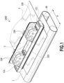
- the liquid ejection head 3 includes a negative pressure control unit 230 which controls a pressure (a negative pressure) inside a circulation path, a liquid supply unit 220 which communicates with the negative pressure control unit 230 so that a fluid can flow therebetween, a liquid connection portion 111 which serves as an ink supply opening and an ink ejection opening of the liquid supply unit 220, and a casing 80.
- the print medium 2 is not limited to a cut sheet and may be also a continuous roll medium.
- the liquid ejection head 3 can print a full color image by inks of cyan C, magenta M, yellow Y, and black K and is fluid-connected to a liquid supply member, a main tank, and a buffer tank (see Fig.
- the control unit which supplies power and transmits an ejection control signal to the liquid ejection head 3 is electrically connected to the liquid ejection head 3.
- the liquid path and the electric signal path in the liquid ejection head 3 will be described later.
- the printing apparatus 1000 is an inkjet printing apparatus that circulates a liquid such as ink between a tank and the liquid ejection head 3 to be described later.
- various circulation configuration including a first circulation configuration and a second circulation configuration, which are described below, can be applied.
- the first circulation configuration is a configuration in which the liquid is circulated by the activation of two circulation pumps (for high and low pressures) at the downstream side of the liquid ejection head 3.
- a second circulation configuration is a configuration in which the liquid is circulated by the activation of two circulation pumps (for high and low pressures) at the upstream side of the liquid ejection head 3.
- the first circulation configuration and the second circulation configuration of the circulation will be described.
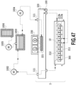
- Fig. 2 is a schematic diagram illustrating the first circulation configuration in the circulation path applied to the printing apparatus 1000 of the application example.
- the liquid ejection head 3 is fluid-connected to a first circulation pump (the high pressure side) 1001, a first circulation pump (the low pressure side) 1002, and a buffer tank 1003. Further, in Fig. 2 , in order to simplify a description, a path through which ink of one color of cyan C, magenta M, yellow Y, and black K flows is illustrated. However, in fact, four colors of circulation paths are provided in the liquid ejection head 3 and the printing apparatus body.
- ink inside a main tank 1006 is supplied into the buffer tank 1003 by a replenishing pump 1005 and then is supplied to the liquid supply unit 220 of the liquid ejection head 3 through the liquid connection portion 111 by a second circulation pump 1004. Subsequently, the ink which is adjusted to two different negative pressures (high and low pressures) by the negative pressure control unit 230 connected to the liquid supply unit 220 is circulated while being divided into two passages having the high and low pressures.
- the buffer tank 1003 which is a sub-tank includes an atmosphere communication opening (not illustrated) which is connected to the main tank 1006 to communicate the inside of the tank with the outside and thus can discharge bubbles inside the ink to the outside.
- the replenishing pump 1005 is provided between the buffer tank 1003 and the main tank 1006. The replenishing pump 1005 delivers the ink from the main tank 1006 to the buffer tank 1003 after the ink is consumed by the ejection (the ink ejection) of the ink from the ejection opening of the liquid ejection head 3 in the printing operation and the suction collection operation.
- the first circulation pump (the high pressure side) 1001 and the first circulation pump (the low pressure side) 1002 are operated so that the ink flows at a predetermined flow rate through a common supply passage 211 and a common collection passage 212. Since the ink flows in this way, the temperature of the liquid ejection head 3 during a printing operation is kept at an optimal temperature.
- the predetermined flow rate when the liquid ejection head 3 is driven is desirably set to be equal to or higher than a flow rate at which a difference in temperature among the printing element boards 10 inside the liquid ejection head 3 does not influence printing quality.
- the upstream side of the negative pressure control unit 230 is pressurized by the second circulation pump 1004 through the liquid supply unit 220.
- Fig. 3 is a schematic diagram illustrating the second circulation configuration which is a circulation configuration different from the first circulation configuration in the circulation path applied to the printing apparatus of the application example.
- a main difference from the first circulation configuration is that two negative pressure control mechanisms constituting the negative pressure control unit 230 both control a pressure at the upstream side of the negative pressure control unit 230 within a predetermined range from a desired set pressure.
- the second circulation pump 1004 serves as a negative pressure source which reduces a pressure at the downstream side of the negative pressure control unit 230.
- first circulation pump (the high pressure side) 1001 and the first circulation pump (the low pressure side) 1002 are disposed at the upstream side of the liquid ejection head 3 and the negative pressure control unit 230 is disposed at the downstream side of the liquid ejection head 3.
- the ink circulated inside the liquid ejection head by the action of the first circulation pump (the high pressure side) 1001 and the first circulation pump (the low pressure side) 1002 is discharged from the liquid ejection head 3 through the liquid connection portion 111 by the negative pressure control unit 230.
- the discharged ink is returned to the buffer tank 1003 by the second circulation pump 1004.
- the negative pressure control unit 230 stabilizes a change in pressure at the upstream side (that is, the liquid ejection unit 300) of the negative pressure control unit 230 within a predetermined range from a predetermined pressure even when a change in flow rate is caused by a change in ejection amount per unit area.
- the downstream side of the negative pressure control unit 230 is pressurized by the second circulation pump 1004 through the liquid supply unit 220.
- the negative pressure control unit 230 includes two negative pressure control mechanisms respectively having different control pressures.
- a high pressure side indicated by "H” in Fig. 3
- a low pressure side indicated by "L” in Fig. 3
- a high pressure side indicated by "H” in Fig. 3
- a low pressure side indicated by "L” in Fig. 3
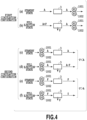
- Fig. 4 is a schematic diagram illustrating a difference in ink inflow amount to the liquid ejection head 3 between the first circulation configuration and the second circulation configuration.
- Fig. 4-(a) illustrates the standby state in the first circulation configuration
- Fig. 4-(b) illustrates the full ejection state in the first circulation configuration.
- Fig. 4-(c) to Fig. 4-(f) illustrate the second circulation passage.
- Fig. 4-(c) and Fig. 4-(d) illustrate a case where the flow rate F is lower than the flow rate A
- Fig. 4-(e) and Fig. 4-(f) illustrate a case where the flow rate F is higher than the flow rate A. In this way, the flow rates in the standby state and the full ejection state are illustrated.
- the first to third passage members be formed of a material having corrosion resistance with respect to a liquid and having a low linear expansion coefficient.
- a material for example, a composite material (resin) obtained by adding inorganic filler such as fiber or fine silica particles to a base material such as alumina, LCP (liquid crystal polymer), PPS (polyphenyl sulfide), PSF (polysulfone), or modified PPE (polyphenylene ether) can be appropriately used.
- a method of forming the passage member 210 three passage members may be laminated and adhered to one another. When a resin composite material is selected as a material, a bonding method using welding may be used.
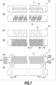
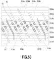
- Fig. 8 is a partially enlarged perspective view illustrating a part ⁇ of Fig. 7-(a) and illustrating the passages inside the passage member 210 formed by bonding the first to third passage members to one another when viewed from a face onto which the ejection module 200 is mounted in the first passage member 50.
- the common supply passage 211 and the common collection passage 212 are formed such that the common supply passage 211 and the common collection passage 212 are alternately disposed from the passages of both ends.
- a connection relation among the passages inside the passage member 210 will be described.
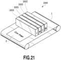
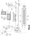
- the supply system, the buffer tank 1003 (see Figs. 2 and 3 ), and the main tank 1006 (see Figs. 2 and 3 ) of the printing apparatus 2000 are fluid-connected to the liquid ejection heads 2003. Further, an electrical control unit which transmits power and ejection control signals to the liquid ejection head 2003 is electrically connected to the liquid ejection heads 2003.
- the first, second and third circulation configurations illustrated in Fig. 2 , Fig. 3 of Fig. 47 can be used as the liquid circulation configuration between the printing apparatus 2000 and the liquid ejection head 2003.
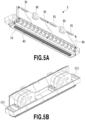
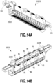
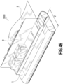
- Figs. 14A and 14B are perspective views illustrating the liquid ejection head 2003 according to the application example.
- the liquid ejection head 2003 is an inkjet line type (page wide type) print head which includes sixteen printing element boards 2010 arranged linearly in the longitudinal direction of the liquid ejection head 2003 and can print an image by one kind of liquid.
- the liquid ejection head 2003 includes the liquid connection portion 111, the signal input terminal 91, and the power supply terminal 92.
- the liquid ejection head 2003 of the application example includes many ejection opening rows compared with the first application example, the signal input terminal 91 and the power supply terminal 92 are disposed at both sides of the liquid ejection head 2003. This is because a decrease in voltage or a delay in transmission of a signal caused by the wiring portion provided in the printing element board 2010 needs to be reduced.
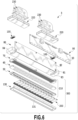
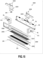
- Fig. 15 is an oblique exploded view illustrating the liquid ejection head 2003 and components or units constituting the liquid ejection head 2003 according to the functions thereof.
- the function of each of units and members or the liquid flow sequence inside the liquid ejection head is basically similar to that of the first application example, but the function of guaranteeing the rigidity of the liquid ejection head is different.
- the rigidity of the liquid ejection head is mainly guaranteed by the liquid ejection unit support portion 81, but in the liquid ejection head 2003 of the second application example, the rigidity of the liquid ejection head is guaranteed by a second passage member 2060 included in a liquid ejection unit 2300.
- the liquid ejection unit support portion 81 of the application example is connected to both ends of the second passage member 2060 and the liquid ejection unit 2300 is mechanically connected to a carriage of the printing apparatus 2000 to position the liquid ejection head 2003.
- the electric wiring board 90 and a liquid supply unit 2220 including a negative pressure control unit 2230 are connected to the liquid ejection unit support portion 81.
- Each of two liquid supply units 2220 includes a filter (not illustrated) built therein.
- the passage member 2210 is obtained by laminating a first passage member 2050 and a second passage member 2060 and distributes the liquid supplied from the liquid supply unit 2220 to ejection modules 2200.
- the passage member 2210 serves as a passage member that returns the liquid re-circulated from the ejection module 2200 to the liquid supply unit 2220.
- the second passage member 2060 of the passage member 2210 is a passage member having a common supply passage and a common collection passage formed therein and improving the rigidity of the liquid ejection head 2003. For this reason, it is desirable that a material of the second passage member 2060 have sufficient corrosion resistance for the liquid and high mechanical strength. Specifically, SUS, Ti, or alumina can be used.
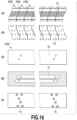
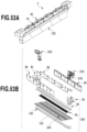
- Fig. 16-(a) shows a diagram illustrating a face onto which the ejection module 2200 is mounted in the first passage member 2050
- Fig. 16-(b) shows a diagram illustrating a rear face thereof and a face contacting the second passage member 2060.
- the first passage member 2050 of the application example has a configuration in which a plurality of members are disposed adjacently to respectively correspond to the ejection modules 2200.
- a plurality of modules can be arranged to correspond to a length of the liquid ejection head 2003. Accordingly, this structure can be appropriately used particularly in a relatively long liquid ejection head corresponding to, for example, a sheet having a size of B2 or more.
- Fig. 16-(a) the communication opening 51 of the first passage member 2050 fluid-communicates with the ejection module 2200.
- the individual communication opening 53 of the first passage member 2050 fluid-communicates with the communication opening 61 of the second passage member 2060.
- Fig. 16-(c) illustrates a contact face of the second passage member 60 with respect to the first passage member 2050
- Fig. 16-(d) illustrates a cross-section of a center portion of the second passage member 60 in the thickness direction
- Fig. 16-(e) shows a diagram illustrating a contact face of the second passage member 2060 with respect to the liquid supply unit 2220.
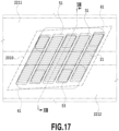
- Fig. 17 is a perspective view illustrating a liquid connection relation between the printing element board 2010 and the passage member 2210.
- a pair of the common supply passage 2211 and the common collection passage 2212 extending in the longitudinal direction of the liquid ejection head 2003 is provided inside the passage member 2210.
- the communication opening 61 of the second passage member 2060 is connected to the individual communication opening 53 of the first passage member 2050 so that both positions match each other.
- the liquid supply passage communicating with the communication opening 51 of the first passage member 2050 through the communication opening 61 from the common supply passage 2211 of the second passage member 2060 is formed.
- the liquid the supply path communicating with the communication opening 51 of the first passage member 2050 through the common collection passage 2212 from the communication opening 72 of the second passage member 2060 is also formed.
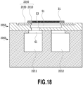
- Fig. 18 is a cross-sectional view taken along a line XVIII-XVIII of Fig. 17 .
- the common supply passage 2211 is connected to the ejection module 2200 through the communication opening 61, the individual communication opening 53, and the communication opening 51.
- the common collection passage 2212 is connected to the ejection module 2200 by the same path in a different cross-section in Fig. 17 .
- each of the ejection module 2200 and the printing element board 2010 is provided with a passage communicating with each ejection opening and thus a part or the entirety of the supplied liquid can be re-circulated while passing through the ejection opening that does not perform the ejection operation.
- the common supply passage 2211 is connected to the negative pressure control unit 2230 (the high pressure side) and the common collection passage 2212 is connected to the negative pressure control unit 2230 (the low pressure side) through the liquid supply unit 2220.
- a flow is formed so that the liquid flows from the common supply passage 2211 to the common collection passage 2212 through the pressure chamber of the printing element board 2010 by the differential pressure.
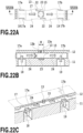
- Fig. 19A is a perspective view illustrating one ejection module 2200 and Fig. 19B is an exploded view thereof.
- the terminals 16 are respectively disposed at both sides (the long side portions of the printing element board 2010) in the ejection opening row directions of the printing element board 2010.
- two flexible circuit boards 40 electrically connected to the printing element board 2010 are disposed for each printing element board 2010. Since the number of the ejection opening rows provided in the printing element board 2010 is twenty, the ejection opening rows are more than eight ejection opening rows of the first application example.
- the liquid communication opening 31 of the support member 2030 is opened along the entire ejection opening row provided in the printing element board 2010.
- the other configurations are similar to those of the first application example.
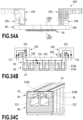
- the liquid connection portion 111 and the filter 221 are provided inside the liquid supply unit 220 and the negative pressure control unit 230 is integrally formed at the lower side of the liquid supply unit 220. Accordingly, a distance between the negative pressure control unit 230 and the printing element board 10 in the height direction becomes short compared with the second application example. With this configuration, the number of the passage connection portions inside the liquid supply unit 220 decreases. As a result, there is an advantage that the reliability of preventing the leakage of the printing liquid is improved and the number of components or assembly steps decreases.
- a water head difference between the negative pressure control unit 230 and the ejection opening forming face of the liquid ejection head 3 decreases relatively, this configuration can be suitably applied to the printing apparatus in which the inclination angle of the liquid ejection head 3 illustrated in Fig. 51 is different for each of the liquid ejection heads. Since the water head difference can be decreased, a difference in negative pressure applied to the ejection openings of the printing element boards can be reduced even when the liquid ejection heads 3 having different inclination angles are used. Further, since a distance from the negative pressure control unit 230 to the printing element board 10 decreases, a flow resistance therebetween decreases. Accordingly, a difference in pressure loss caused by a change in flow rate of the liquid decreases and thus the negative pressure can be more desirably controlled.
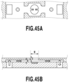
- Fig. 54C is a perspective view illustrating a cross-section taken along a line LIVC-LIVC of Fig. 54A .
- each ejection module 200 includes the first passage member 50, the printing element board 10, and the flexible circuit board 40.
- the support member 30 ( Fig. 18 ) described in the second application example does not exist and the printing element board 10 including the lid member 20 is directly bonded to the first passage member 50.
- the liquid is supplied from the communication opening 61 formed at the upper face of the common supply passage 211 provided at the second passage member to the individual supply passage 213a through the individual communication opening 53 formed at the lower face of the first passage member 50. Subsequently, the liquid passes through the pressure chamber 23 and passes through the individual collection passage 213b, the individual communication opening 53, and the communication opening 61 to be collected to the common collection passage 212.
- the invention can be also applied to a so-called serial type liquid ejection head which prints an image on the print medium while scanning the print medium.
- the serial type liquid ejection head for example, the liquid ejection head may be equipped with a printing element board ejecting black ink and a printing element board ejecting color ink, but the invention is not limited thereto.
- a liquid ejection head which is shorter than the width of the print medium and includes a plurality of printing element boards disposed so that the ejection openings overlap each other in the ejection opening row direction may be provided and the print medium may be scanned by the liquid ejection head.
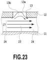
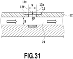
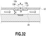
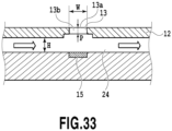
- a differential pressure that causes ink circulation causes the flow of ink supplied from a liquid supply path (supply passage) 18 through a supply opening 17a provided in the substrate 11 to pass through the passage 24, the pressure chamber 23, and the passage 24, and arrive at a liquid collection path (outflow passage) 19 through a collection opening 17b.
- a space from the printing element (energy generation element) 15 to an ejection opening 13 above the printing element 15 is full of ink in a non-ejection state, and a meniscus of ink (ink boundary 13a) is formed around an end portion of the ejection opening 13 at a side in an ejection direction.
- the ink boundary is indicated by a straight line (plane) in Fig. 22B .
- a shape thereof is determined according to a member that forms a wall of the ejection opening 13 and ink surface tension. Normally, the shape becomes a curved line (curved surface) having a concave or convex shape.
- the ink boundary is indicated by the straight line to simplify illustration.
- a liquid droplet of ink ejected from the ejection opening includes ink in the ejection opening portion 13b and ink in the pressure chamber 23 (the passage 24) to be ejected in a mixed state.
- a rate of the ink from the pressure chamber 23 is greater than a rate of ink from the ejection opening portion in the ejected liquid droplet.
- This condition corresponds to for example a case in which a bubble generating for ejection communicates with an outer air.
- a liquid ejection head which has sizes of H being equal to or less than 20 ⁇ m, P being equal to or less than 20 ⁇ m and W being equal to or less than 30 ⁇ m and is then capable of performing higher-definition printing, is desirable.
- the embodiment can suppress variation in a quality of liquid adjacent to the ejection opening and thus can achieve suppressing increase of ink viscosity due to liquid evaporation from the ejection opening and reducing color unevenness in an image.
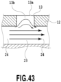
- the ink flow 17 flowing into the passage 24 flows into the ejection opening portion 13b, arrives at a position adjacent to the ink boundary 13a (a meniscus position), and then returns to the passage 24 again through the inside of the ejection opening portion 13b.
- Ink returning to the passage 24 flows to the common collection passage 212 described above through a liquid collection path 19.
- Such ink flow allows not only the ink inside the ejection opening portion 13b at which the influence of evaporation is easily received but also the ink near the ink boundary 13a at which an influence of evaporation is particularly remarkable to flow out to the passage 24 without staying inside the ejection opening portion 13b.
- ink around the ejection opening particularly at a position at which an influence of evaporation of ink moisture, etc. is easily received, may be allowed to flow out without staying there, and it is possible to inhibit ink from thickening or ink color material concentration from increasing.
- the present embodiment may inhibit at least a portion of the ink boundary 13a from increasing in viscosity, and thus may further reduce an influence on ejection such as a change in ejection velocity, etc. when compared to a case in which the entire ink boundary 13a increases in viscosity.
- the above-described ink flow 17 of the present embodiment has a velocity component in a flow direction of ink (a direction from a left side to a right side in Fig. 23 ) inside the passage 24 (hereinafter referred to as a positive velocity component) at least at a central portion around the ink boundary 13a (a central portion of the ejection opening).
- a flow mode in which the ink flow 17 has a positive velocity component at least at the central portion around the ink boundary 13a is referred to as a "flow mode A”.
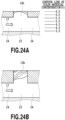
- a flow mode in which the ink flow 17 has a negative velocity component in an opposite direction to that of the positive velocity component at the central portion around the ink boundary 13a as in a comparative example described below is referred to as a "flow mode B".
- FIG. 24B illustrates a state of the flow mode B when ink flows in at 1.26 ⁇ 10 -4 ml/min from the liquid supply path 18 to the passage 24 of the liquid ejection head which has a shape in which H is 14 ⁇ m, P is 11 ⁇ m, and W is 12.4 ⁇ m.
- Color material concentration of ink inside the ejection opening portion 13b is higher in the flow mode B illustrated in Fig. 24B than in the flow mode A illustrated in Fig. 24A .
- ink inside the ejection opening portion 13b may be replaced (allowed to flow out) up to the passage 24 by the ink flow 17 arriving at a portion around the ink boundary 13a with a positive velocity component. In this way, ink inside the ejection opening portion 13b may be inhibited from staying. As a result, it is possible to suppress an increase in color material concentration and viscosity.
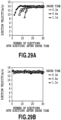
- Fig. 25 is a diagram for description of a comparison between color material concentration of ink ejected from a liquid ejection head (head A) that generates the flow mode A and color material concentration of ink ejected from a liquid ejection head (head B) that generates the flow mode B.
- This figure illustrates data corresponding to a case in which ink is ejected while the ink flow 17 is generated in the passage 24 and a case in which ink is ejected while the ink flow 17 is not generated and no ink flow is present inside the passage in each of head A and head B.
- a density ratio becomes 1.3 or more after an elapsed time of 1 second or more in both the heads A and B, and color material concentration of ink rises in a relatively short time.
- a density ratio is in a range up to about 1.3, and an increase in color material concentration may be suppressed when compared to a case in which any ink flow is not generated.
- ink having increased color material concentration which corresponds to a density ratio of up to 1.3, stays in the ejection opening portion.
- a range of a color material concentration ratio is 1.1 or less.
- a human has difficulty in visually recognizing color unevenness when a change in color material concentration is about 1.2 or less.
- the head A suppresses a change in color material concentration which causes color unevenness to be visually recognized, even when an elapsed time is about 1.5 second and therefore is much desirable than the head B.
- Fig. 25 illustrates a case in which color material concentration increases with evaporation.
- the liquid ejection head of the present embodiment may similarly suppress a change in color material concentration when color material concentration decreases with evaporation.
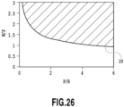
- a relation among H, P, and W corresponds to the flow mode A in a liquid ejection head present in a region indicated by diagonal lines above the threshold line 20, and corresponds to the flow mode B in a liquid ejection head present in a region below and on the threshold line 20.
- the relation corresponds to the flow mode A in a liquid ejection head that satisfies Expression (4) below.
- W/P > 1.7 ⁇ P/H ⁇ 0.34
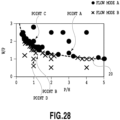
- a circulation flow velocity V17 necessary to obtain the state C rather than the state D is proportional to an evaporation flow velocity V12 in one liquid ejection head.
- the circulation flow velocity necessary to obtain the state C increases as the determination value J decreases.
- the determination value J is 2.83 corresponding to a smallest value (the liquid ejection head 1), the state C is obtained when the circulation flow velocity is set to be 27 times or more the evaporation flow velocity.
- H is 3 ⁇ m or more and 6 ⁇ m or less
- P is 3 ⁇ m or more and 6 ⁇ m or less
- W is 17 ⁇ m or more and 30 ⁇ m or less.
- a flow velocity of liquid in a passage is 27 times or more a rate of evaporation from an ejection opening.
- the above regulation of the flow velocity of liquid corresponds to a range in which the state C is obtained even when a most difficult shape to obtain the state C in each head shape range is used.
- the state C may be obtained at a smaller flow velocity.
- Vd is 5 pl
- a plurality of main droplets and sub-droplets (hereinafter also referred to as satellites) are easily generated when the ejection amount is large, and the droplets cause deterioration of image quality.
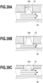
- Figs. 39A to 39C are diagrams illustrating flow modes of three passage shapes A to C.
- Fig. 40 is a contour line diagram illustrating a value of the determination value J when a diameter of an ejection opening is changed such that the ejection amount Vd corresponds to about 5 pl.
- a horizontal axis indicates H
- a vertical axis indicates P.
- a flow of an ink flow easily enters an inside of the ejection opening when compared to the passage shape B, and ink may be further inhibited from staying inside the ejection opening portion 13b. Therefore, shapes below are given with regard to flow modes of an ink flow.
- Figs. 41A to 41C are diagrams illustrating results of observing ejected liquid droplets of the respective three types of passage shapes A to C.
- Fig. 42 is a contour line diagram illustrating a value obtained by calculating a time at which bubbles communicate with the atmosphere (hereinafter also referred to as Tth) when a diameter of an ejection opening is changed such that the ejection amount Vd corresponds to about 5 pl.
- Tth a horizontal axis indicates H
- a vertical axis indicates P.
- Figs. 41A and 41C illustrate a case in which two types of ejected liquid droplets corresponding to a main droplet and a satellite are generated. Meanwhile, Fig. 41B illustrates a case in which a main droplet and a plurality of satellites are generated.
- Tth equals 5.8 us.
- Tth equals 4.5 us.
- Tth equals 3.8 us, and Tth becomes small (see Fig. 42 ).
- a plurality of satellites are generated when the ejection amount Vd is large as in the present embodiment, and when Tth is small since an elongated tail (tailing) is easily generated, and a lot of nodes resulting from the unstable tail are generated when Tth is small, that is, communication with the atmosphere is facilitated.
- the number of elongated tails may not be reduced to one, and a plurality of satellites are generated as illustrated in Fig. 41B . Therefore, restraints below may be imposed with regard to the satellites.
- a range illustrated in Fig. 42 is preferably adopted.
- the determination value Tth satisfies the above condition
- the above equation indicates that Tth decreases and a plurality of satellites are easily generated when H or P decreases or Z increases.
- H has sensitivity which is about 1.5 times as high as sensitivity of P.
- a decrease in Tth may be suppressed, and generation of satellites may be suppressed when P is set to be small. Therefore, the above condition may be represented by the following expression. 0.350 ⁇ H + 0.227 ⁇ P ⁇ 0.100 ⁇ Z > 4
- a change in a quality of a liquid near an ejection opening can be suppressed and thus it is possible for example to suppress increase in ink viscosity due to liquid evaporation through the ejection opening and to reduce color unevenness in an image.
- Expression (2) described in the second embodiment it is possible to obtain the flow mode A, and to inhibit ink from staying inside the ejection opening portion 13b. In this way, it is possible to reduce an increase in color material concentration.
- a flow velocity of ink flowing through the passage 24 may be appropriately set depending on the condition, the environment, etc. in which the liquid ejection head is used according to approaches described in the present embodiment.
Landscapes
- Physics & Mathematics (AREA)
- Geometry (AREA)
- Ink Jet (AREA)
- Particle Formation And Scattering Control In Inkjet Printers (AREA)
Claims (12)
- Verfahren zum Zuführen einer Flüssigkeit in einem Flüssigkeitsausstoßkopf (3), der enthält: eine Ausstoßöffnung (13) zum Ausstoßen einer Flüssigkeit, einen Durchlass (24), in dem ein Energieerzeugungselement zum Erzeugen von zum Ausstoßen der Flüssigkeit verwendeter Energie angeordnet ist, einen Ausstoßöffnungsabschnitt (13b), der Kommunizieren zwischen der Ausstoßöffnung und dem Durchlass zulässt, einen Zufuhrdurchlass (18), der Strömen der Flüssigkeit von außen in den Durchlass ermöglicht, und einen Ausströmdurchlass (19), der Strömen der Flüssigkeit vom Durchlass nach außen ermöglicht;wobei das Zuführen der Flüssigkeit so durchgeführt wird, dass die Flüssigkeit von außen durch den Zufuhrdurchlass in den Durchlass strömt und aus dem Durchlass durch den Ausströmdurchlass nach außen strömt; undein Strömen der Flüssigkeit so erzeugt wird, dass die Flüssigkeit, die vom Durchlass nach innerhalb des Ausstoßabschnitts gelangt, an einer Position ankommt, die innerhalb des Ausstoßöffnungsabschnitts in einer Richtung, in der die innerhalb des Ausstoßöffnungsabschnitts befindliche Flüssigkeit ausgestoßen wird, mindestens der Hälfte entspricht, und dann in den Durchlass zurückkehrt,dadurch gekennzeichnet, dass:eine Höhe H des Durchlasses an einer in einer Strömungsrichtung der Flüssigkeit innerhalb des Durchgangs stromaufwärtigen Seite eines Kommunikationsabschnitts zwischen dem Durchlass und der Ausstoßöffnung 20 µm oder weniger beträgt,eine Länge P des Ausstoßöffnungsabschnitts in einer Richtung, in der die Flüssigkeit aus der Ausstoßöffnung ausgestoßen wird, 20 µm oder weniger beträgt,eine Länge W des Ausstoßöffnungsabschnitts in der Strömungsrichtung der Flüssigkeit innerhalb des Durchgangs 30 µm oder weniger beträgt, undwobei ein Ausdruck H-0,34 × P-0,66 × W > 1,5 erfüllt ist.
- Verfahren nach Anspruch 1, wobei die Höhe H 14 µm oder weniger beträgt, die Länge P 12 µm oder weniger beträgt, die Länge W 17 µm oder mehr beträgt, und eine Strömungsgeschwindigkeit der Flüssigkeit im Durchlass das 900-fache oder mehr einer Verdunstungsrate von der Ausstoßöffnung beträgt.
- Verfahren nach Anspruch 1, wobei die Höhe H 15 µm oder weniger beträgt, die Länge P 7 µm oder weniger beträgt, die Länge W 17 µm oder mehr beträgt, und eine Strömungsgeschwindigkeit der Flüssigkeit im Durchlass das 100-fache oder mehr einer Verdunstungsrate von der Ausstoßöffnung beträgt.
- Verfahren nach Anspruch 1, wobei die Höhe H 8 µm oder weniger beträgt, die Länge P 8 µm oder weniger beträgt, die Länge W 17 µm oder mehr beträgt, und eine Strömungsgeschwindigkeit der Flüssigkeit im Durchlass das 50-fache oder mehr einer Verdunstungsrate von der Ausstoßöffnung beträgt.
- Verfahren nach Anspruch 1, wobei die Höhe H 3 µm oder mehr und 6 µm oder weniger beträgt, die Länge P 3 µm oder mehr und 6 µm oder weniger beträgt, die Länge W 17 µm oder mehr beträgt, und eine Strömungsgeschwindigkeit der Flüssigkeit im Durchlass das 27-fache oder mehr einer Verdunstungsrate von der Ausstoßöffnung beträgt.
- Verfahren nach einem der vorhergehenden Ansprüche, wobei eine Viskosität der im Durchlass strömenden Flüssigkeit 30 cP oder weniger beträgt und eine Strömungsgeschwindigkeit der Flüssigkeit in einem Bereich von 0,1 bis 100 mm/s liegt.
- Verfahren nach einem der vorhergehenden Ansprüche, wobei ein Feststoffgehalt der Flüssigkeit 8 Gewichtsprozent oder mehr beträgt.
- Verfahren nach einem der vorhergehenden Ansprüche, wobei das Energieerzeugungselement ein Heizelement ist und eine durch Anwenden von Hitze durch das Heizelement erzeugte Blase durch die Ausstoßöffnung mit Luft außerhalb kommuniziert.
- Verfahren nach einem der vorhergehenden Ansprüche, wobei die Höhe H des Durchlasses niedriger ist als eine Höhe des Durchlasses in einem Kommunikationsabschnitt zwischen dem Durchlass und dem Zufuhrdurchlass.
- Verfahren nach einem der vorhergehenden Ansprüche, weiterhin umfassend:eine Öffnungsplatte, in der die Ausstoßöffnung gebildet ist,wobei eine Dicke der Öffnungsplatte um die Ausstoßöffnung herum dünner ist als eine Dicke der Öffnungsplatte in einem Kommunikationsabschnitt zwischen dem Durchlass und dem Zufuhrdurchlass.
- Verfahren nach einem der vorhergehenden Ansprüche, weiterhin umfassend:eine Öffnungsplatte, in der die Ausstoßöffnung gebildet ist,wobei auf der Öffnungsplatte ein konkaver Abschnitt gebildet ist und die Ausstoßöffnung innerhalb des konkaven Abschnitts gebildet ist.
- Verfahren nach einem der vorhergehenden Ansprüche,wobei die Strömung der Flüssigkeit so erzeugt wird, dass die Flüssigkeit, die vom Durchlass nach innerhalb des Ausstoßöffnungsabschnitts gelangt, an einer Position eines in der Ausstoßöffnung gebildeten Meniskus der Flüssigkeit ankommt und dann in den Durchlass zurückkehrt, undwobei ein Ausdruck H-0,34 × P-0,66 × W > 1,7 erfüllt ist.
Applications Claiming Priority (4)
| Application Number | Priority Date | Filing Date | Title |
|---|---|---|---|
| JP2016003078 | 2016-01-08 | ||
| JP2016238891A JP6929639B2 (ja) | 2016-01-08 | 2016-12-08 | 液体吐出ヘッド、液体吐出装置及び液体の供給方法 |
| EP19196259.6A EP3616918B1 (de) | 2016-01-08 | 2017-01-06 | Flüssigkeitsausstosskopf und flüssigkeitsausstossvorrichtung und verfahren zur zuführung von flüsigkeit |
| EP17000025.1A EP3189971B1 (de) | 2016-01-08 | 2017-01-06 | Flüssigkeitsausstosskopf, flüssigkeitsausstossvorrichtung und verfahren zur zuführung von flüssigkeit |
Related Parent Applications (3)
| Application Number | Title | Priority Date | Filing Date |
|---|---|---|---|
| EP19196259.6A Division EP3616918B1 (de) | 2016-01-08 | 2017-01-06 | Flüssigkeitsausstosskopf und flüssigkeitsausstossvorrichtung und verfahren zur zuführung von flüsigkeit |
| EP19196259.6A Division-Into EP3616918B1 (de) | 2016-01-08 | 2017-01-06 | Flüssigkeitsausstosskopf und flüssigkeitsausstossvorrichtung und verfahren zur zuführung von flüsigkeit |
| EP17000025.1A Division EP3189971B1 (de) | 2016-01-08 | 2017-01-06 | Flüssigkeitsausstosskopf, flüssigkeitsausstossvorrichtung und verfahren zur zuführung von flüssigkeit |
Publications (2)
| Publication Number | Publication Date |
|---|---|
| EP4116102A1 EP4116102A1 (de) | 2023-01-11 |
| EP4116102B1 true EP4116102B1 (de) | 2024-07-03 |
Family
ID=59364788
Family Applications (1)
| Application Number | Title | Priority Date | Filing Date |
|---|---|---|---|
| EP22186453.1A Active EP4116102B1 (de) | 2016-01-08 | 2017-01-06 | Verfahren zum zuführen von flüssigkeit |
Country Status (9)
| Country | Link |
|---|---|
| US (2) | US12319064B2 (de) |
| EP (1) | EP4116102B1 (de) |
| JP (4) | JP6929639B2 (de) |
| KR (1) | KR102116403B1 (de) |
| CN (2) | CN110682683B (de) |
| AU (1) | AU2016277746B2 (de) |
| BR (1) | BR102017000226B1 (de) |
| MY (1) | MY189027A (de) |
| RU (2) | RU2674275C2 (de) |
Families Citing this family (14)
| Publication number | Priority date | Publication date | Assignee | Title |
|---|---|---|---|---|
| JP6929639B2 (ja) | 2016-01-08 | 2021-09-01 | キヤノン株式会社 | 液体吐出ヘッド、液体吐出装置及び液体の供給方法 |
| US10040290B2 (en) | 2016-01-08 | 2018-08-07 | Canon Kabushiki Kaisha | Liquid ejection head, liquid ejection apparatus, and method of supplying liquid |
| JP7005196B2 (ja) * | 2017-07-07 | 2022-01-21 | キヤノン株式会社 | 液体吐出ヘッド及び液体吐出装置 |
| JP7118716B2 (ja) * | 2018-04-17 | 2022-08-16 | キヤノン株式会社 | 液体吐出ヘッド |
| CN111559173B (zh) * | 2019-02-13 | 2022-10-21 | 精工爱普生株式会社 | 液体喷射装置 |
| US11179935B2 (en) * | 2019-02-19 | 2021-11-23 | Canon Kabushiki Kaisha | Liquid ejection head, liquid ejection module, and method of manufacturing liquid ejection head |
| JP7419008B2 (ja) * | 2019-10-01 | 2024-01-22 | キヤノン株式会社 | 液体吐出ヘッド |
| JP7400346B2 (ja) * | 2019-10-28 | 2023-12-19 | セイコーエプソン株式会社 | 液体吐出ヘッドおよび液体吐出装置 |
| JP7467090B2 (ja) | 2019-12-05 | 2024-04-15 | キヤノン株式会社 | 液体吐出ヘッド |
| US20230001692A1 (en) * | 2020-02-14 | 2023-01-05 | Hewlett-Packard Development Company, L.P. | Droplet delivery |
| WO2022066166A1 (en) * | 2020-09-25 | 2022-03-31 | Hewlett-Packard Development Company, L.P. | Fluidic dies including discharge circuits |
| JP7632052B2 (ja) * | 2021-05-14 | 2025-02-19 | セイコーエプソン株式会社 | 液体吐出ヘッドおよび液体吐出装置 |
| US12350934B2 (en) | 2022-07-05 | 2025-07-08 | Canon Kabushiki Kaisha | Liquid ejection head and liquid ejection apparatus |
| JP2024179100A (ja) * | 2023-06-14 | 2024-12-26 | キヤノン株式会社 | 液体吐出ヘッド及び液体吐出装置 |
Family Cites Families (50)
| Publication number | Priority date | Publication date | Assignee | Title |
|---|---|---|---|---|
| EP0317171A3 (de) * | 1987-11-13 | 1990-07-18 | Hewlett-Packard Company | Integrales Dünnschicht-Injektionssystem für einen thermischen Tintenspritzdruckkopf und Arbeitsmethoden |
| US5087930A (en) | 1989-11-01 | 1992-02-11 | Tektronix, Inc. | Drop-on-demand ink jet print head |
| JPH08267758A (ja) * | 1995-03-28 | 1996-10-15 | Sony Corp | オリフィスプレート、オリフィスプレートの製造方法、液体混合装置およびプリンタ装置 |
| JPH10151761A (ja) * | 1996-11-21 | 1998-06-09 | Brother Ind Ltd | インクジェット記録装置 |
| US5818485A (en) | 1996-11-22 | 1998-10-06 | Xerox Corporation | Thermal ink jet printing system with continuous ink circulation through a printhead |
| US6350016B1 (en) * | 1998-02-10 | 2002-02-26 | Canon Kabushiki Kaisha | Liquid ejecting method and liquid ejecting head |
| US6254214B1 (en) * | 1999-06-11 | 2001-07-03 | Lexmark International, Inc. | System for cooling and maintaining an inkjet print head at a constant temperature |
| JP2001113698A (ja) * | 1999-10-19 | 2001-04-24 | Nec Niigata Ltd | ノズルプレート及びその製造方法及びインクジェット記録ヘッド |
| JP2002355973A (ja) * | 2001-05-31 | 2002-12-10 | Kyocera Corp | インクジェットヘッド |
| JP2003025577A (ja) | 2001-07-11 | 2003-01-29 | Canon Inc | 液体吐出ヘッド |
| JP2003063005A (ja) * | 2001-08-29 | 2003-03-05 | Kyocera Corp | インクジェット記録ヘッド |
| US6874865B2 (en) * | 2001-09-10 | 2005-04-05 | Sony Corporation | Printer head chip and printer head |
| JP2003276189A (ja) | 2002-03-20 | 2003-09-30 | Fuji Photo Film Co Ltd | 液滴吐出装置およびインクジェット記録ヘッド |
| JP5728148B2 (ja) | 2006-04-27 | 2015-06-03 | 東芝テック株式会社 | インクジェット装置およびその制御方法 |
| US7997709B2 (en) | 2006-06-20 | 2011-08-16 | Eastman Kodak Company | Drop on demand print head with fluid stagnation point at nozzle opening |
| JP2008030361A (ja) * | 2006-07-31 | 2008-02-14 | Fuji Xerox Co Ltd | 液滴吐出ヘッド、及びこれを備えた画像形成装置 |
| JP4851310B2 (ja) * | 2006-12-06 | 2012-01-11 | 富士フイルム株式会社 | 液滴吐出機構および画像形成装置 |
| US7850290B2 (en) | 2006-12-28 | 2010-12-14 | Toshiba Tec Kabushiki Kaisha | Ink jet recording apparatus, ink supplying mechanism and ink supplying method |
| US20080158321A1 (en) * | 2006-12-28 | 2008-07-03 | Toshiba Tec Kabushiki Kaisha | Ink jet recording apparatus, ink supplying mechanism and ink jet recording method |
| JP5020708B2 (ja) * | 2007-05-25 | 2012-09-05 | キヤノン株式会社 | 液体吐出ヘッドおよびインクジェット記録装置 |
| JP2009233945A (ja) * | 2008-03-26 | 2009-10-15 | Toshiba Tec Corp | 液体吐出装置およびその製造方法 |
| JP2009255513A (ja) | 2008-03-26 | 2009-11-05 | Seiko Epson Corp | 液体吐出方法、液体吐出ヘッド、及び、液体吐出装置 |
| JP4516996B2 (ja) * | 2008-09-29 | 2010-08-04 | シャープ株式会社 | インクジェットヘッドおよびその製造方法 |
| WO2010044775A1 (en) * | 2008-10-14 | 2010-04-22 | Hewlett-Packard Development Company, L.P. | Fluid ejector structure |
| JP5371475B2 (ja) * | 2009-02-17 | 2013-12-18 | キヤノン株式会社 | インクジェット記録ヘッド及びそのクリーニング方法 |
| US8113627B2 (en) | 2009-06-19 | 2012-02-14 | Eastman Kodak Company | Micro-fluidic actuator for inkjet printers |
| JP5335580B2 (ja) * | 2009-06-30 | 2013-11-06 | キヤノン株式会社 | 液体吐出装置 |
| US8182073B2 (en) | 2009-06-30 | 2012-05-22 | Eastman Kodak Company | Flow through dispenser including diverter cooling channel |
| WO2011005699A2 (en) * | 2009-07-10 | 2011-01-13 | Fujifilm Dimatix, Inc. | Mems jetting structure for dense packing |
| US8342659B2 (en) | 2009-08-25 | 2013-01-01 | Canon Kabushiki Kaisha | Liquid discharge head and method for manufacturing the same |
| JP2011062867A (ja) * | 2009-09-16 | 2011-03-31 | Toshiba Tec Corp | インクジェットヘッド |
| JP5475399B2 (ja) | 2009-10-30 | 2014-04-16 | 花王株式会社 | インクジェット記録用水分散体 |
| CN102218919B (zh) * | 2010-04-01 | 2014-09-24 | 精工爱普生株式会社 | 液体喷射头、液体喷射单元及液体喷射装置 |
| US8540355B2 (en) * | 2010-07-11 | 2013-09-24 | Hewlett-Packard Development Company, L.P. | Fluid ejection device with circulation pump |
| WO2012015397A1 (en) * | 2010-07-28 | 2012-02-02 | Hewlett-Packard Development Company, L.P. | Fluid ejection assembly with circulation pump |
| EP2629976B1 (de) | 2010-10-19 | 2021-04-21 | Hewlett-Packard Development Company, L.P. | Druckmodul mit zweifachregler |
| US8657429B2 (en) * | 2010-10-26 | 2014-02-25 | Eastman Kodak Company | Dispensing liquid using overlapping outlet/return dispenser |
| US8517518B2 (en) * | 2010-11-09 | 2013-08-27 | Canon Kabushiki Kaisha | Recording apparatus and liquid ejection head |
| US8794745B2 (en) | 2011-02-09 | 2014-08-05 | Canon Kabushiki Kaisha | Liquid ejection head and liquid ejection method |
| US8652767B2 (en) | 2011-02-28 | 2014-02-18 | Canon Kabushiki Kaisha | Liquid ejection head and process for producing the same |
| JP5863336B2 (ja) | 2011-08-25 | 2016-02-16 | キヤノン株式会社 | インクジェット記録ヘッドおよびインク吐出方法 |
| JP5615307B2 (ja) * | 2012-02-14 | 2014-10-29 | 富士フイルム株式会社 | 液滴吐出装置 |
| US9403372B2 (en) * | 2012-02-28 | 2016-08-02 | Hewlett-Packard Development Company, L.P. | Fluid ejection device with ACEO pump |
| US9156262B2 (en) | 2012-04-27 | 2015-10-13 | Hewlett-Packard Development Company, L.P. | Fluid ejection device with two-layer tophat |
| WO2014021812A1 (en) | 2012-07-30 | 2014-02-06 | Hewlett-Packard Development Company L.P. | Printhead including integrated circuit die cooling |
| JP6335599B2 (ja) | 2013-05-02 | 2018-05-30 | キヤノン株式会社 | 液体吐出ヘッド及びインクジェット記録装置 |
| JP6536130B2 (ja) | 2015-03-31 | 2019-07-03 | ブラザー工業株式会社 | 液体吐出ヘッド、及び、液体吐出装置 |
| WO2017010996A1 (en) | 2015-07-14 | 2017-01-19 | Hewlett-Packard Development Company, L.P. | Fluid recirculation channels |
| US10040290B2 (en) | 2016-01-08 | 2018-08-07 | Canon Kabushiki Kaisha | Liquid ejection head, liquid ejection apparatus, and method of supplying liquid |
| JP6929639B2 (ja) | 2016-01-08 | 2021-09-01 | キヤノン株式会社 | 液体吐出ヘッド、液体吐出装置及び液体の供給方法 |
-
2016
- 2016-12-08 JP JP2016238891A patent/JP6929639B2/ja active Active
- 2016-12-23 AU AU2016277746A patent/AU2016277746B2/en active Active
- 2016-12-28 RU RU2016151769A patent/RU2674275C2/ru active
- 2016-12-28 RU RU2018139533A patent/RU2705331C2/ru active
-
2017
- 2017-01-03 MY MYPI2017700019A patent/MY189027A/en unknown
- 2017-01-05 BR BR102017000226-8A patent/BR102017000226B1/pt active IP Right Grant
- 2017-01-06 CN CN201911003119.3A patent/CN110682683B/zh active Active
- 2017-01-06 EP EP22186453.1A patent/EP4116102B1/de active Active
- 2017-01-06 CN CN201710008691.3A patent/CN106956513B/zh active Active
- 2017-01-06 KR KR1020170002207A patent/KR102116403B1/ko active Active
-
2021
- 2021-08-04 JP JP2021128493A patent/JP2021169225A/ja active Pending
-
2022
- 2022-04-21 US US17/726,232 patent/US12319064B2/en active Active
-
2023
- 2023-01-16 JP JP2023004333A patent/JP7764414B2/ja active Active
-
2024
- 2024-10-02 JP JP2024173921A patent/JP2024177357A/ja not_active Withdrawn
-
2025
- 2025-02-10 US US19/049,735 patent/US20250178352A1/en active Pending
Also Published As
| Publication number | Publication date |
|---|---|
| RU2674275C2 (ru) | 2018-12-06 |
| AU2016277746B2 (en) | 2021-09-09 |
| CN106956513B (zh) | 2019-11-05 |
| EP4116102A1 (de) | 2023-01-11 |
| AU2016277746A1 (en) | 2017-07-27 |
| JP6929639B2 (ja) | 2021-09-01 |
| KR20170083502A (ko) | 2017-07-18 |
| CN106956513A (zh) | 2017-07-18 |
| KR102116403B1 (ko) | 2020-05-29 |
| RU2705331C2 (ru) | 2019-11-06 |
| RU2016151769A3 (de) | 2018-07-03 |
| JP7764414B2 (ja) | 2025-11-05 |
| US20250178352A1 (en) | 2025-06-05 |
| JP2017124610A (ja) | 2017-07-20 |
| JP2024177357A (ja) | 2024-12-19 |
| BR102017000226A2 (pt) | 2017-07-18 |
| US20220250388A1 (en) | 2022-08-11 |
| US12319064B2 (en) | 2025-06-03 |
| JP2021169225A (ja) | 2021-10-28 |
| BR102017000226B1 (pt) | 2024-01-02 |
| CN110682683B (zh) | 2021-10-08 |
| RU2016151769A (ru) | 2018-07-03 |
| MY189027A (en) | 2022-01-20 |
| RU2018139533A3 (de) | 2019-08-28 |
| CN110682683A (zh) | 2020-01-14 |
| JP2023029648A (ja) | 2023-03-03 |
| RU2018139533A (ru) | 2019-03-20 |
Similar Documents
| Publication | Publication Date | Title |
|---|---|---|
| EP3616918B1 (de) | Flüssigkeitsausstosskopf und flüssigkeitsausstossvorrichtung und verfahren zur zuführung von flüsigkeit | |
| US20220250388A1 (en) | Liquid ejection head, liquid ejection apparatus, and method of supplying liquid | |
| EP3196027B1 (de) | Flüssigkeitsausstosskopf und flüssigkeitsausstossvorrichtung | |
| JP7118700B2 (ja) | 画像形成装置および画像形成装置の制御方法 | |
| US9931845B2 (en) | Liquid ejection module and liquid ejection head | |
| EP3424727B1 (de) | Flüssigkeitsausstosskopf, flüssigkeitsausstossvorrichtung und flüssigkeitsausstossverfahren | |
| EP3192657A1 (de) | Flüssigkeitsausstosssubstrat, flüssigkeitsausstosskopf und flüssigkeitsausstossvorrichtung | |
| EP3192656B1 (de) | Flüssigkeitsabgabekopf und flüssigkeitsabgabeverfahren | |
| JP6987497B2 (ja) | 液体吐出モジュールおよび液体吐出ヘッド | |
| JP6740041B2 (ja) | 液体吐出方法、液体吐出装置、および液体吐出ヘッド | |
| JP7182984B2 (ja) | 液体吐出ヘッドおよび液体吐出装置 | |
| JP6862165B2 (ja) | 液体吐出装置および液体吐出方法 | |
| JP6900179B2 (ja) | 液体吐出ヘッド | |
| JP7171356B2 (ja) | 液体吐出ヘッド及び液体吐出装置 | |
| JP2020059167A (ja) | 液体吐出ヘッド及び液体吐出装置 |
Legal Events
| Date | Code | Title | Description |
|---|---|---|---|
| PUAI | Public reference made under article 153(3) epc to a published international application that has entered the european phase |
Free format text: ORIGINAL CODE: 0009012 |
|
| STAA | Information on the status of an ep patent application or granted ep patent |
Free format text: STATUS: THE APPLICATION HAS BEEN PUBLISHED |
|
| AC | Divisional application: reference to earlier application |
Ref document number: 3189971 Country of ref document: EP Kind code of ref document: P Ref document number: 3616918 Country of ref document: EP Kind code of ref document: P |
|
| AK | Designated contracting states |
Kind code of ref document: A1 Designated state(s): AL AT BE BG CH CY CZ DE DK EE ES FI FR GB GR HR HU IE IS IT LI LT LU LV MC MK MT NL NO PL PT RO RS SE SI SK SM TR |
|
| STAA | Information on the status of an ep patent application or granted ep patent |
Free format text: STATUS: REQUEST FOR EXAMINATION WAS MADE |
|
| 17P | Request for examination filed |
Effective date: 20230711 |
|
| RBV | Designated contracting states (corrected) |
Designated state(s): AL AT BE BG CH CY CZ DE DK EE ES FI FR GB GR HR HU IE IS IT LI LT LU LV MC MK MT NL NO PL PT RO RS SE SI SK SM TR |
|
| GRAP | Despatch of communication of intention to grant a patent |
Free format text: ORIGINAL CODE: EPIDOSNIGR1 |
|
| STAA | Information on the status of an ep patent application or granted ep patent |
Free format text: STATUS: GRANT OF PATENT IS INTENDED |
|
| INTG | Intention to grant announced |
Effective date: 20240205 |
|
| GRAS | Grant fee paid |
Free format text: ORIGINAL CODE: EPIDOSNIGR3 |
|
| GRAA | (expected) grant |
Free format text: ORIGINAL CODE: 0009210 |
|
| STAA | Information on the status of an ep patent application or granted ep patent |
Free format text: STATUS: THE PATENT HAS BEEN GRANTED |
|
| AC | Divisional application: reference to earlier application |
Ref document number: 3189971 Country of ref document: EP Kind code of ref document: P Ref document number: 3616918 Country of ref document: EP Kind code of ref document: P |
|
| AK | Designated contracting states |
Kind code of ref document: B1 Designated state(s): AL AT BE BG CH CY CZ DE DK EE ES FI FR GB GR HR HU IE IS IT LI LT LU LV MC MK MT NL NO PL PT RO RS SE SI SK SM TR |
|
| REG | Reference to a national code |
Ref country code: CH Ref legal event code: EP |
|
| REG | Reference to a national code |
Ref country code: DE Ref legal event code: R096 Ref document number: 602017083140 Country of ref document: DE |
|
| REG | Reference to a national code |
Ref country code: LT Ref legal event code: MG9D |
|
| REG | Reference to a national code |
Ref country code: NL Ref legal event code: MP Effective date: 20240703 |
|
| PG25 | Lapsed in a contracting state [announced via postgrant information from national office to epo] |
Ref country code: PT Free format text: LAPSE BECAUSE OF FAILURE TO SUBMIT A TRANSLATION OF THE DESCRIPTION OR TO PAY THE FEE WITHIN THE PRESCRIBED TIME-LIMIT Effective date: 20241104 |
|
| REG | Reference to a national code |
Ref country code: AT Ref legal event code: MK05 Ref document number: 1699439 Country of ref document: AT Kind code of ref document: T Effective date: 20240703 |
|
| PG25 | Lapsed in a contracting state [announced via postgrant information from national office to epo] |
Ref country code: NL Free format text: LAPSE BECAUSE OF FAILURE TO SUBMIT A TRANSLATION OF THE DESCRIPTION OR TO PAY THE FEE WITHIN THE PRESCRIBED TIME-LIMIT Effective date: 20240703 |
|
| PG25 | Lapsed in a contracting state [announced via postgrant information from national office to epo] |
Ref country code: PT Free format text: LAPSE BECAUSE OF FAILURE TO SUBMIT A TRANSLATION OF THE DESCRIPTION OR TO PAY THE FEE WITHIN THE PRESCRIBED TIME-LIMIT Effective date: 20241104 Ref country code: NL Free format text: LAPSE BECAUSE OF FAILURE TO SUBMIT A TRANSLATION OF THE DESCRIPTION OR TO PAY THE FEE WITHIN THE PRESCRIBED TIME-LIMIT Effective date: 20240703 |
|
| PG25 | Lapsed in a contracting state [announced via postgrant information from national office to epo] |
Ref country code: NO Free format text: LAPSE BECAUSE OF FAILURE TO SUBMIT A TRANSLATION OF THE DESCRIPTION OR TO PAY THE FEE WITHIN THE PRESCRIBED TIME-LIMIT Effective date: 20241003 |
|
| PG25 | Lapsed in a contracting state [announced via postgrant information from national office to epo] |
Ref country code: GR Free format text: LAPSE BECAUSE OF FAILURE TO SUBMIT A TRANSLATION OF THE DESCRIPTION OR TO PAY THE FEE WITHIN THE PRESCRIBED TIME-LIMIT Effective date: 20241004 Ref country code: FI Free format text: LAPSE BECAUSE OF FAILURE TO SUBMIT A TRANSLATION OF THE DESCRIPTION OR TO PAY THE FEE WITHIN THE PRESCRIBED TIME-LIMIT Effective date: 20240703 Ref country code: PL Free format text: LAPSE BECAUSE OF FAILURE TO SUBMIT A TRANSLATION OF THE DESCRIPTION OR TO PAY THE FEE WITHIN THE PRESCRIBED TIME-LIMIT Effective date: 20240703 |
|
| PG25 | Lapsed in a contracting state [announced via postgrant information from national office to epo] |
Ref country code: BG Free format text: LAPSE BECAUSE OF FAILURE TO SUBMIT A TRANSLATION OF THE DESCRIPTION OR TO PAY THE FEE WITHIN THE PRESCRIBED TIME-LIMIT Effective date: 20240703 |
|
| PG25 | Lapsed in a contracting state [announced via postgrant information from national office to epo] |
Ref country code: LV Free format text: LAPSE BECAUSE OF FAILURE TO SUBMIT A TRANSLATION OF THE DESCRIPTION OR TO PAY THE FEE WITHIN THE PRESCRIBED TIME-LIMIT Effective date: 20240703 |
|
| PG25 | Lapsed in a contracting state [announced via postgrant information from national office to epo] |
Ref country code: IS Free format text: LAPSE BECAUSE OF FAILURE TO SUBMIT A TRANSLATION OF THE DESCRIPTION OR TO PAY THE FEE WITHIN THE PRESCRIBED TIME-LIMIT Effective date: 20241103 Ref country code: AT Free format text: LAPSE BECAUSE OF FAILURE TO SUBMIT A TRANSLATION OF THE DESCRIPTION OR TO PAY THE FEE WITHIN THE PRESCRIBED TIME-LIMIT Effective date: 20240703 |
|
| PG25 | Lapsed in a contracting state [announced via postgrant information from national office to epo] |
Ref country code: HR Free format text: LAPSE BECAUSE OF FAILURE TO SUBMIT A TRANSLATION OF THE DESCRIPTION OR TO PAY THE FEE WITHIN THE PRESCRIBED TIME-LIMIT Effective date: 20240703 Ref country code: CZ Free format text: LAPSE BECAUSE OF FAILURE TO SUBMIT A TRANSLATION OF THE DESCRIPTION OR TO PAY THE FEE WITHIN THE PRESCRIBED TIME-LIMIT Effective date: 20240703 |
|
| PG25 | Lapsed in a contracting state [announced via postgrant information from national office to epo] |
Ref country code: RS Free format text: LAPSE BECAUSE OF FAILURE TO SUBMIT A TRANSLATION OF THE DESCRIPTION OR TO PAY THE FEE WITHIN THE PRESCRIBED TIME-LIMIT Effective date: 20241003 Ref country code: ES Free format text: LAPSE BECAUSE OF FAILURE TO SUBMIT A TRANSLATION OF THE DESCRIPTION OR TO PAY THE FEE WITHIN THE PRESCRIBED TIME-LIMIT Effective date: 20240703 |
|
| PG25 | Lapsed in a contracting state [announced via postgrant information from national office to epo] |
Ref country code: RS Free format text: LAPSE BECAUSE OF FAILURE TO SUBMIT A TRANSLATION OF THE DESCRIPTION OR TO PAY THE FEE WITHIN THE PRESCRIBED TIME-LIMIT Effective date: 20241003 Ref country code: PL Free format text: LAPSE BECAUSE OF FAILURE TO SUBMIT A TRANSLATION OF THE DESCRIPTION OR TO PAY THE FEE WITHIN THE PRESCRIBED TIME-LIMIT Effective date: 20240703 Ref country code: NO Free format text: LAPSE BECAUSE OF FAILURE TO SUBMIT A TRANSLATION OF THE DESCRIPTION OR TO PAY THE FEE WITHIN THE PRESCRIBED TIME-LIMIT Effective date: 20241003 Ref country code: LV Free format text: LAPSE BECAUSE OF FAILURE TO SUBMIT A TRANSLATION OF THE DESCRIPTION OR TO PAY THE FEE WITHIN THE PRESCRIBED TIME-LIMIT Effective date: 20240703 Ref country code: IS Free format text: LAPSE BECAUSE OF FAILURE TO SUBMIT A TRANSLATION OF THE DESCRIPTION OR TO PAY THE FEE WITHIN THE PRESCRIBED TIME-LIMIT Effective date: 20241103 Ref country code: HR Free format text: LAPSE BECAUSE OF FAILURE TO SUBMIT A TRANSLATION OF THE DESCRIPTION OR TO PAY THE FEE WITHIN THE PRESCRIBED TIME-LIMIT Effective date: 20240703 Ref country code: GR Free format text: LAPSE BECAUSE OF FAILURE TO SUBMIT A TRANSLATION OF THE DESCRIPTION OR TO PAY THE FEE WITHIN THE PRESCRIBED TIME-LIMIT Effective date: 20241004 Ref country code: FI Free format text: LAPSE BECAUSE OF FAILURE TO SUBMIT A TRANSLATION OF THE DESCRIPTION OR TO PAY THE FEE WITHIN THE PRESCRIBED TIME-LIMIT Effective date: 20240703 Ref country code: ES Free format text: LAPSE BECAUSE OF FAILURE TO SUBMIT A TRANSLATION OF THE DESCRIPTION OR TO PAY THE FEE WITHIN THE PRESCRIBED TIME-LIMIT Effective date: 20240703 Ref country code: CZ Free format text: LAPSE BECAUSE OF FAILURE TO SUBMIT A TRANSLATION OF THE DESCRIPTION OR TO PAY THE FEE WITHIN THE PRESCRIBED TIME-LIMIT Effective date: 20240703 Ref country code: BG Free format text: LAPSE BECAUSE OF FAILURE TO SUBMIT A TRANSLATION OF THE DESCRIPTION OR TO PAY THE FEE WITHIN THE PRESCRIBED TIME-LIMIT Effective date: 20240703 Ref country code: AT Free format text: LAPSE BECAUSE OF FAILURE TO SUBMIT A TRANSLATION OF THE DESCRIPTION OR TO PAY THE FEE WITHIN THE PRESCRIBED TIME-LIMIT Effective date: 20240703 |
|
| REG | Reference to a national code |
Ref country code: DE Ref legal event code: R097 Ref document number: 602017083140 Country of ref document: DE |
|
| PGFP | Annual fee paid to national office [announced via postgrant information from national office to epo] |
Ref country code: DE Payment date: 20241218 Year of fee payment: 9 |
|
| PG25 | Lapsed in a contracting state [announced via postgrant information from national office to epo] |
Ref country code: DK Free format text: LAPSE BECAUSE OF FAILURE TO SUBMIT A TRANSLATION OF THE DESCRIPTION OR TO PAY THE FEE WITHIN THE PRESCRIBED TIME-LIMIT Effective date: 20240703 Ref country code: RO Free format text: LAPSE BECAUSE OF FAILURE TO SUBMIT A TRANSLATION OF THE DESCRIPTION OR TO PAY THE FEE WITHIN THE PRESCRIBED TIME-LIMIT Effective date: 20240703 Ref country code: SM Free format text: LAPSE BECAUSE OF FAILURE TO SUBMIT A TRANSLATION OF THE DESCRIPTION OR TO PAY THE FEE WITHIN THE PRESCRIBED TIME-LIMIT Effective date: 20240703 |
|
| PG25 | Lapsed in a contracting state [announced via postgrant information from national office to epo] |
Ref country code: EE Free format text: LAPSE BECAUSE OF FAILURE TO SUBMIT A TRANSLATION OF THE DESCRIPTION OR TO PAY THE FEE WITHIN THE PRESCRIBED TIME-LIMIT Effective date: 20240703 |
|
| PG25 | Lapsed in a contracting state [announced via postgrant information from national office to epo] |
Ref country code: IT Free format text: LAPSE BECAUSE OF FAILURE TO SUBMIT A TRANSLATION OF THE DESCRIPTION OR TO PAY THE FEE WITHIN THE PRESCRIBED TIME-LIMIT Effective date: 20240703 Ref country code: SK Free format text: LAPSE BECAUSE OF FAILURE TO SUBMIT A TRANSLATION OF THE DESCRIPTION OR TO PAY THE FEE WITHIN THE PRESCRIBED TIME-LIMIT Effective date: 20240703 |
|
| PLBE | No opposition filed within time limit |
Free format text: ORIGINAL CODE: 0009261 |
|
| STAA | Information on the status of an ep patent application or granted ep patent |
Free format text: STATUS: NO OPPOSITION FILED WITHIN TIME LIMIT |
|
| 26N | No opposition filed |
Effective date: 20250404 |
|
| REG | Reference to a national code |
Ref country code: CH Ref legal event code: PL |
|
| PG25 | Lapsed in a contracting state [announced via postgrant information from national office to epo] |
Ref country code: SE Free format text: LAPSE BECAUSE OF FAILURE TO SUBMIT A TRANSLATION OF THE DESCRIPTION OR TO PAY THE FEE WITHIN THE PRESCRIBED TIME-LIMIT Effective date: 20240703 |
|
| PG25 | Lapsed in a contracting state [announced via postgrant information from national office to epo] |
Ref country code: MC Free format text: LAPSE BECAUSE OF FAILURE TO SUBMIT A TRANSLATION OF THE DESCRIPTION OR TO PAY THE FEE WITHIN THE PRESCRIBED TIME-LIMIT Effective date: 20240703 Ref country code: LU Free format text: LAPSE BECAUSE OF NON-PAYMENT OF DUE FEES Effective date: 20250106 |
|
| PG25 | Lapsed in a contracting state [announced via postgrant information from national office to epo] |
Ref country code: BE Free format text: LAPSE BECAUSE OF NON-PAYMENT OF DUE FEES Effective date: 20250131 |
|
| PG25 | Lapsed in a contracting state [announced via postgrant information from national office to epo] |
Ref country code: FR Free format text: LAPSE BECAUSE OF NON-PAYMENT OF DUE FEES Effective date: 20250131 |
|
| PG25 | Lapsed in a contracting state [announced via postgrant information from national office to epo] |
Ref country code: CH Free format text: LAPSE BECAUSE OF NON-PAYMENT OF DUE FEES Effective date: 20250131 |
|
| REG | Reference to a national code |
Ref country code: BE Ref legal event code: MM Effective date: 20250131 |
|
| PGFP | Annual fee paid to national office [announced via postgrant information from national office to epo] |
Ref country code: GB Payment date: 20251217 Year of fee payment: 10 |
|
| PG25 | Lapsed in a contracting state [announced via postgrant information from national office to epo] |
Ref country code: IE Free format text: LAPSE BECAUSE OF NON-PAYMENT OF DUE FEES Effective date: 20250106 |