EP4115767A1 - Vivarien-unterschrank - Google Patents
Vivarien-unterschrank Download PDFInfo
- Publication number
- EP4115767A1 EP4115767A1 EP22175012.8A EP22175012A EP4115767A1 EP 4115767 A1 EP4115767 A1 EP 4115767A1 EP 22175012 A EP22175012 A EP 22175012A EP 4115767 A1 EP4115767 A1 EP 4115767A1
- Authority
- EP
- European Patent Office
- Prior art keywords
- recess
- base cabinet
- magnetic closure
- closure element
- magnetic
- Prior art date
- Legal status (The legal status is an assumption and is not a legal conclusion. Google has not performed a legal analysis and makes no representation as to the accuracy of the status listed.)
- Granted
Links
Images


Classifications
-
- A—HUMAN NECESSITIES
- A47—FURNITURE; DOMESTIC ARTICLES OR APPLIANCES; COFFEE MILLS; SPICE MILLS; SUCTION CLEANERS IN GENERAL
- A47B—TABLES; DESKS; OFFICE FURNITURE; CABINETS; DRAWERS; GENERAL DETAILS OF FURNITURE
- A47B81/00—Cabinets or racks specially adapted for other particular purposes, e.g. for storing guns or skis
-
- A—HUMAN NECESSITIES
- A01—AGRICULTURE; FORESTRY; ANIMAL HUSBANDRY; HUNTING; TRAPPING; FISHING
- A01K—ANIMAL HUSBANDRY; AVICULTURE; APICULTURE; PISCICULTURE; FISHING; REARING OR BREEDING ANIMALS, NOT OTHERWISE PROVIDED FOR; NEW BREEDS OF ANIMALS
- A01K63/00—Receptacles for live fish, e.g. aquaria; Terraria
- A01K63/003—Aquaria; Terraria
-
- A—HUMAN NECESSITIES
- A01—AGRICULTURE; FORESTRY; ANIMAL HUSBANDRY; HUNTING; TRAPPING; FISHING
- A01K—ANIMAL HUSBANDRY; AVICULTURE; APICULTURE; PISCICULTURE; FISHING; REARING OR BREEDING ANIMALS, NOT OTHERWISE PROVIDED FOR; NEW BREEDS OF ANIMALS
- A01K63/00—Receptacles for live fish, e.g. aquaria; Terraria
- A01K63/003—Aquaria; Terraria
- A01K63/006—Accessories for aquaria or terraria
-
- A—HUMAN NECESSITIES
- A47—FURNITURE; DOMESTIC ARTICLES OR APPLIANCES; COFFEE MILLS; SPICE MILLS; SUCTION CLEANERS IN GENERAL
- A47B—TABLES; DESKS; OFFICE FURNITURE; CABINETS; DRAWERS; GENERAL DETAILS OF FURNITURE
- A47B21/00—Tables or desks for office equipment, e.g. typewriters, keyboards
- A47B21/06—Tables or desks for office equipment, e.g. typewriters, keyboards characterised by means for holding, fastening or concealing cables
-
- A—HUMAN NECESSITIES
- A47—FURNITURE; DOMESTIC ARTICLES OR APPLIANCES; COFFEE MILLS; SPICE MILLS; SUCTION CLEANERS IN GENERAL
- A47B—TABLES; DESKS; OFFICE FURNITURE; CABINETS; DRAWERS; GENERAL DETAILS OF FURNITURE
- A47B96/00—Details of cabinets, racks or shelf units not covered by a single one of groups A47B43/00 - A47B95/00; General details of furniture
-
- A—HUMAN NECESSITIES
- A47—FURNITURE; DOMESTIC ARTICLES OR APPLIANCES; COFFEE MILLS; SPICE MILLS; SUCTION CLEANERS IN GENERAL
- A47B—TABLES; DESKS; OFFICE FURNITURE; CABINETS; DRAWERS; GENERAL DETAILS OF FURNITURE
- A47B96/00—Details of cabinets, racks or shelf units not covered by a single one of groups A47B43/00 - A47B95/00; General details of furniture
- A47B96/20—Furniture panels or like furniture elements
-
- A—HUMAN NECESSITIES
- A47—FURNITURE; DOMESTIC ARTICLES OR APPLIANCES; COFFEE MILLS; SPICE MILLS; SUCTION CLEANERS IN GENERAL
- A47B—TABLES; DESKS; OFFICE FURNITURE; CABINETS; DRAWERS; GENERAL DETAILS OF FURNITURE
- A47B96/00—Details of cabinets, racks or shelf units not covered by a single one of groups A47B43/00 - A47B95/00; General details of furniture
- A47B96/20—Furniture panels or like furniture elements
- A47B2096/209—Magnetic decorative panels
-
- A—HUMAN NECESSITIES
- A47—FURNITURE; DOMESTIC ARTICLES OR APPLIANCES; COFFEE MILLS; SPICE MILLS; SUCTION CLEANERS IN GENERAL
- A47B—TABLES; DESKS; OFFICE FURNITURE; CABINETS; DRAWERS; GENERAL DETAILS OF FURNITURE
- A47B2200/00—General construction of tables or desks
- A47B2200/14—Aquarium table
-
- A—HUMAN NECESSITIES
- A47—FURNITURE; DOMESTIC ARTICLES OR APPLIANCES; COFFEE MILLS; SPICE MILLS; SUCTION CLEANERS IN GENERAL
- A47B—TABLES; DESKS; OFFICE FURNITURE; CABINETS; DRAWERS; GENERAL DETAILS OF FURNITURE
- A47B2220/00—General furniture construction, e.g. fittings
Definitions
- the present invention relates to a base cabinet for vivariums, in particular aquariums.
- Base cabinets for vivariums accommodate the technical equipment required for the operation of a vivarium, such as devices for lighting control and/or temperature control.
- the base cabinet can also accommodate external filters for filtration of the aquarium water.
- power supply lines as well as inlet and outlet lines for the water taken from the aquarium or the water returned to the aquarium must be provided.
- the object of the present invention is to provide a base cabinet that enables a visually appealing and at the same time particularly easy-to-use feed-through for these lines.
- the present object is achieved by a base cabinet with side walls, wherein at least one side wall has a recess and at least one first magnetic closure element arranged adjacent to the recess. Furthermore, the base cabinet has at least one screen element that can be introduced into the recess and at least partially closes the recess in the installed position.
- the panel element has a second magnetic closure element, the second magnetic closure element being arranged in the installation position of the panel element in the recess corresponding to the first magnetic closure is. In the installed position, the screen element is held exclusively by magnetic forces acting between the first magnetic closure element and the second magnetic closure element. There are no other fittings such as hinges to be provided or present.
- Limiting stops for the screen element are not necessary, but can be provided to simplify the insertion of the screen element into the recess.
- the recess can be designed in a simple manner and, when the screen element is removed from the recess, is free of fittings which could impede the passage of cables through the recess.
- the screen element can easily be inserted into the recess and removed from the recess without tools. By dispensing with further fittings, such a base cabinet is easy to produce and enables a clear, visually appealing appearance both with and without a panel element introduced into the recess.
- the first magnetic closure element is arranged in such a way that it can interact magnetically with the second magnetic closure element of the panel element in an installed position, with the magnetic forces between the first and the second magnetic closure element being large enough , to set the screen element in the recess.
- the first and/or second magnetic closure element is designed as a magnetic element, in particular as a permanent magnet.
- the respective other magnetic closure element can also be designed as a magnetic element, in particular as a permanent magnet.
- the respective other magnetic closure element is preferably made of one non-magnetic but magnetizable ferromagnetic element, in particular made of a magnetizable steel material.
- the second magnetic closure element is preferably designed as a non-magnetic but magnetizable element.
- the screen element is therefore non-magnetic and therefore easier to stow away.
- the screen element can be arranged inside the base cabinet when not in use, without magnetically interacting with the technology of the vivarium arranged in the base cabinet, such as lighting control, temperature control or possibly a filter system. Such a screen element is particularly easy to handle.
- the first magnetic closure element is embedded in an end face of the side wall that delimits the recess.
- the first magnetic element can be arranged adjacent to the recess.
- the screen element can be easily centered via the magnetic forces within the recess.
- this type of arrangement of the first magnetic element enables a visually particularly clear and thus appealing design of the base cabinet.
- the second magnetic closure element is embedded in a side of the panel element which, in an installation situation of the panel element, faces the end face of the side wall delimiting the recess.
- the first magnetic closure element and the second magnetic closure element which is arranged on the panel element in a manner corresponding to the first magnetic closure element, have opposite surfaces in the installation situation with approximately the same spatial dimensions. If the first magnetic closure element and the second magnetic closure element have opposing surfaces, in particular cross-sectional surfaces, with approximately the same spatial dimensions, the centering of the screen element in the installed position is not only relative to an outer surface of the side wall, but also in a direction parallel to the outer surface particularly easy. If the first and the second magnetic closure element have, for example, round or rectangular cross-sections with the same area, these tend to be arranged exactly one above the other in the installation situation. As a result, the installation position of the screen element in the recess can be precisely specified in a simple manner.
- the first magnetic closure element or the second magnetic closure element can be configured as an element that extends over a large area.
- this planar element is made of a non-magnetic, however magnetizable material created.
- a screen element that only partially closes the recess can be arranged along the planar extent of the respective magnetic closure element in different positions, displaced in the recess along the planar extent of the magnetic closure element.
- the at least one screen element can preferably be fixed flush with an outer surface of the base cabinet in the recess. This enables a particularly clear and visually appealing design of the base cabinet.
- Known panels that can be used in recesses for cable bushings and are mechanically fixed there typically have stop areas that extend beyond the recess and with which the panel rests against the outer surface of the side wall. Such a screen thus protrudes from the surface of the side wall and is necessarily larger than the recess.
- the solution according to the invention enables a flush arrangement of the respective outer surfaces of the side wall and panel element and, as a result, a visually particularly attractive appearance of the base cabinet due to the omission of stop surfaces made possible in this way.
- the recess advantageously has a rectangular contour and extends horizontally over the entire side wall of the base cabinet.
- Aquarium base cabinets are designed to be particularly stable in order to be able to absorb the high weight of an aquarium filled with water and to be able to transfer it to the ground.
- Corresponding cabinets for vivariums designed as aquariums have a frame, for example a tubular steel frame, which is preferably arranged on the inside. The load of an aquarium placed on the base cabinet is absorbed by the frame.
- the side walls of such a base cabinet are not involved in the statics of the base cabinet, but rather represent a cladding element. It is therefore possible in a simple manner to provide a recess in a side wall that extends horizontally over the entire side wall .
- a rectangular contour of this recess enables a particularly attractive appearance of the base cabinet.
- the recess or the panel element to be inserted into the recess can fit into the base cabinet with clear lines.
- the at least one screen element can preferably be fixed in the recess rotated by 180° about a main axis.
- the panel element can have a second magnetic closure element extending through the panel element or a plurality of second magnetic closure elements on opposite sides of the panel element.
- the base cabinet preferably has first magnetic closure elements on opposite sides of the recess, in particular above and below the recess. In this way, a particularly good fit of the panel element in the recess can be achieved.
- the base cabinet comprises at least one set of at least two operating elements of different dimensions that can optionally be introduced into the recess.
- a screen element of the set is designed in such a way that it completely closes the recess in the installation situation.
- At least one further screen element of the set is designed in such a way that it only partially closes the recess.
- the base cabinet forms a cable bushing in the side wall. Even the recess without a screen element forms a cable bushing.
- a cable bushing is typically made larger for the simple introduction of cables than is necessary for the actual cables in operation.
- cable connectors such as plugs are significantly larger than the actual cable.
- the additional screen element makes it possible to close the recess after the cable has been installed and to achieve a visually appealing appearance of the base cabinet.
- the set of panel elements has two, preferably identical, panel elements that in the installation situation Only partially close the recess.
- the first and second magnetic closure elements are arranged in such a way that the two further screen elements can be fixed in the recess in such a way that they form the cable bushing between them. This makes it possible to determine not only the size of the cable bushing, but also the location of the cable bushing in the side wall. For example, it is possible to arrange the cable duct in the center of the recess or to move it towards the rear wall as required.
- the base cabinet can have at least one additional magnetic element embedded in a wall of the base cabinet, but preferably on an inside of a door of the base cabinet that closes the cabinet.
- Tools regularly required for the care of the vivarium, such as scissors, can be arranged in a simple manner on such a magnetic element.
- Tools made of magnetizable material can easily be arranged on this embedded magnetic element and are easily accessible there.
- Tools made of non-magnetizable material can be provided with corresponding elements made of magnetizable or magnetic material in order to be able to be stowed away on such a magnetic element, in particular on the inside of a door of the base cabinet.
- Panel elements that are not required can also be stored there inside the base cabinet.
- FIG. 1 shows a base cabinet 2 according to the invention for vivariums in the form of a base cabinet 2 for an aquarium with an aquarium arranged thereon.
- a cable is shown on the left in the view, which leads to base cabinet 2 for vivariums.
- the base cabinet 2 shows base cabinet 2 for vivariums according to 1 in a side view.
- the base cabinet 2 has a side wall 4 in which a recess 6 is arranged.
- the recess 6 according to 2 has a rectangular contour and extends completely through the side wall 4.
- the recess 6 is closed by a screen element 8 .
- the panel element 8 is designed in such a way that it completely closes the recess 6 in the installation situation.
- the panel element 8 is held in the recess 6 by means of first magnetic closure elements 10 and second magnetic closure elements 12 .
- FIG. 3 shows the arrangement of the first magnetic closure elements 10 and second magnetic closure elements 12.
- Four first magnetic closure elements 10 are arranged in the side wall 4 below the recess 6.
- FIG. The first magnetic closure elements 10 are located immediately adjacent to the recess 6 on the end face of the lower part of the side wall 4.
- the screen element 8 has two second magnetic closure elements 12.
- the first magnetic closure elements 10 are designed as a permanent magnet.
- the second magnetic closure elements 12 are designed as non-magnetic but magnetizable steel pins that are embedded in the screen element 8 .
- the second magnetic closure elements 12 are positioned in the screen element 8 in such a way that they each come to lie opposite one of the first magnetic closure elements 10 when the screen element 8 is installed in the recess 6 .
- the first magnetic closure elements 10 and the second magnetic closure elements 12 interact in such a way that the screen element 8 automatically assumes a specific, predefined position in the recess 6 .
- the first magnetic closure elements 10 and the second magnetic closure elements 12 are aligned coaxially one above the other.
- the panel element 8 can be inserted into the recess 6 without the use of tools and, starting from an interior space of the base cabinet 2 , can be pushed outwards out of the recess 6 . If no stops are provided for the screen element 8 , it can also be pushed out of the recess 6 from the outside in the direction of the interior of the base cabinet 2 . In the installed position, the panel element 8 is aligned flush with the outer surface of the side wall 4 .
- the panel element 8 can be placed in the recess 6 rotated by 180° about each of its three main axes. The operability is thus significantly improved, since it is not necessary to ensure that the panel element 8 is precisely aligned when it is introduced into the recess 6 .
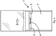
- FIG 4 shows the base cabinet 2 in a view according to FIG 2 .
- the recess 6 is replaced by two further screen elements 8 that only partially close it locked.
- the other panel elements 8 form a cable bushing between them.
- five cables are shown arranged in the cable gland.
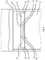
- FIG 5 shows a detailed view 4 , in which the first magnetic closure elements 10 and the second magnetic closure elements 12 are shown.
- Each of the two further panel elements 8 has two second magnetic closure elements 12 which, in an installed position, interact with two first magnetic closure elements 10 each, which are let into the side wall 4 adjacent to the recess 6 .
- the second magnetic closure elements 12 are in turn designed as non-magnetic but magnetizable steel pins.
- the first magnetic closure elements 10 are the same first magnetic closure elements 10 that are already shown in FIG 3 are shown.
- the aperture element 8 which is shown in the illustrations 2 and 3 was arranged in the recess 6, removed and replaced by the two shorter, the recess 6 only partially closing further screen elements 8, which in 4 and 5 are shown replaced.
- the recess 6 in the side wall 4, which is used for cable ducting can be completely closed by a panel element 8 if the cable ducting is not necessary.
- the recess 6 can also be used alternatively by two other screen elements 8 partially so be closed so that they leave an area of the recess 6 free as a cable bushing between them when a cable bushing is required.
- the screen elements 8 can be easily changed without tools due to the magnetic holder and align themselves automatically when inserted into the recess 6 due to the magnetic holder via the first magnetic closure elements 10 and the second magnetic closure elements 12 .
- the second magnetic closure elements 12 can also be in the form of magnets, in particular permanent magnets.
- the first magnetic closure elements 10 can be design as non-magnetic but magnetizable steel pins instead of as magnets.
- the base cabinet 2 can include further sets of panel elements 8 or in a set of panel elements 8 further panel elements.
- the screen elements 8 of an alternative set can be designed differently, e.g. B. be provided with a different decor.
Landscapes
- Life Sciences & Earth Sciences (AREA)
- Environmental Sciences (AREA)
- Marine Sciences & Fisheries (AREA)
- Animal Husbandry (AREA)
- Biodiversity & Conservation Biology (AREA)
- Casings For Electric Apparatus (AREA)
- Shielding Devices Or Components To Electric Or Magnetic Fields (AREA)
- Installation Of Indoor Wiring (AREA)
Abstract
Description
- Die vorliegende Erfindung betrifft einen Unterschrank für Vivarien, insbesondere Aquarien. Unterschränke für Vivarien nehmen die für den Betrieb eines Vivariums notwendige technische Ausstattung wie Vorrichtungen zur Beleuchtungssteuerung und/oder zur Temperaturkontrolle auf. Insbesondere bei der Verwendung als Unterschrank für Aquarien kann der Unterschrank zudem Außenfilter für die Filtration des Aquariumwassers aufnehmen. Für im Inneren des Unterschranks angeordnete Aquarientechnik, insbesondere einen Außenfilter, sind Stromversorgungsleitungen sowie Zu- und Ableitungen für das aus dem Aquarium entnommene Wasser bzw. das zum Aquarium zurückgeführte Wasser vorzusehen. Aufgabe der vorliegenden Erfindung ist es, einen Unterschrank bereitzustellen, der eine optisch ansprechende und gleichzeitig besonders einfach zu bedienende Durchführung für diese Leitungen ermöglicht.
- Die vorliegende Aufgabe wird gelöst durch einen Unterschrank mit Seitenwänden, wobei zumindest eine Seitenwand eine Ausnehmung und zumindest ein benachbart zur Ausnehmung angeordnetes erstes Magnetverschlusselement aufweist. Weiterhin weist der Unterschrank zumindest ein in die Ausnehmung einbringbares und die Ausnehmung in der Einbauposition zumindest teilweise verschließendes Blendenelement auf. Das Blendenelement weist ein zweites Magnetverschlusselement auf, wobei das zweite Magnetverschlusselement in der Einbauposition des Blendenelements in der Ausnehmung korrespondierend zu dem ersten Magnetverschluss angeordnet ist. In der Einbauposition wird das Blendenelement ausschließlich durch zwischen dem ersten Magnetverschlusselement und dem zweiten Magnetverschlusselement wirkende magnetische Kräfte gehalten. Es sind keine weiteren Beschlagteile wie Scharniere vorzusehen oder vorhanden. Begrenzende Anschläge für das Blendenelement sind nicht notwendig, können jedoch zur Vereinfachung des Einsetzens des Blendenelements in die Ausnehmung vorgesehen werden. Die Ausnehmung kann einfach gestaltet werden und ist bei aus der Ausnehmung entferntem Blendenelement frei von Beschlagteilen, die die Durchführung von Kabeln durch die Ausnehmung behindern könnten. Das Blendenelement kann auf einfache Weise werkzeuglos in die Ausnehmung eingesetzt und aus der Ausnehmung entfernt werden. Durch den Verzicht auf weitere Beschlagteile ist ein solcher Unterschrank einfach zu erstellen und ermöglicht ein klares, optisch ansprechendes Erscheinungsbild sowohl mit als auch ohne in die Ausnehmung eingebrachtes Blendenelement.
- Benachbart zur Ausnehmung angeordnet bedeutet im Sinne der Erfindung, dass das erste Magnetverschlusselement so angeordnet ist, dass es mit dem zweiten Magnetverschlusselement des Blendenelements in einer Einbauposition in eine magnetische Wechselwirkung treten kann, wobei die magnetischen Kräfte zwischen dem ersten und dem zweiten Magnetverschlusselement groß genug sind, um das Blendenelement in der Ausnehmung festzulegen. Das erste und/oder zweite Magnetverschlusselement ist hierbei als magnetisches Element, insbesondere als Permanentmagnet, ausgebildet. Das jeweils andere Magnetverschlusselement kann ebenfalls als magnetisches Element, insbesondere als Permanentmagnet, ausgestaltet sein. Vorzugsweise ist das jeweils andere Magnetverschlusselement jedoch aus einem nicht-magnetischen, jedoch magnetisierbaren ferromagnetischen Element, insbesondere aus einem magnetisierbaren Stahlmaterial, ausgestaltet.
- Bevorzugt ist das zweite Magnetverschlusselement als nicht-magnetisches, jedoch magnetisierbares Element ausgebildet. Das Blendenelement ist somit nicht magnetisch und daher einfacher zu verstauen. Insbesondere kann das Blendenelement bei Nichtbenutzung im Inneren des Unterschranks angeordnet werden, ohne mit etwa im Unterschrank angeordneter Technik des Vivariums, wie Beleuchtungssteuerung, Temperatursteuerung oder ggf. einer Filteranlage magnetisch wechselzuwirken. Ein solches Blendenelement ist besonders einfach zu handhaben.
- Mit Vorteil ist das erste Magnetverschlusselement in eine die Ausnehmung begrenzende Stirnseite der Seitenwand eingelassen. Hierdurch kann das erste Magnetelement benachbart zur Ausnehmung angeordnet werden. Gleichzeitig wird so eine einfache Zentrierbarkeit des Blendenelements über die magnetischen Kräfte innerhalb der Ausnehmung erreicht. Zudem ermöglicht diese Art der Anordnung des ersten Magnetelements eine optisch besonders klare und somit ansprechende Gestaltung des Unterschranks.
- Besonders bevorzugt ist das zweite Magnetverschlusselement in eine Seite des Blendenelements eingelassen, das in einer Einbausituation des Blendenelements der die Ausnehmung begrenzenden Stirnseite der Seitenwand zugewandt ist. Diese Anordnung von erstem und zweitem Magnetverschlusselement ermöglicht eine automatische Zentrierung des Blendenelements in der Ausnehmung relativ zu einer nach außen gerichteten Fläche der Seitenwand. Das Blendenelement kann einfach in die Ausnehmung eingebracht werden. Zudem ermöglicht diese Anordnung eine klare und optisch ansprechende Gestaltung des Blendenelements und somit des Schranks.
- Vorzugsweise weisen das erste Magnetverschlusselement und das zu dem ersten Magnetverschlusselement korrespondierend am Blendenelement angeordnete zweite Magnetverschlusselement sich in der Einbausituation gegenüberliegende Flächen mit in etwa gleichen räumlichen Ausdehnungen auf. Wenn das erste Magnetverschlusselement und das zweite Magnetverschlusselement sich einander gegenüberstehende Flächen, insbesondere Querschnittsflächen, mit in etwa gleichen räumlichen Ausdehnungen aufweisen, ist die Zentrierung des Blendenelements in der Einbauposition nicht nur relativ zu einer äußeren Oberfläche der Seitenwand, sondern auch in einer Richtung parallel zu der äußeren Oberfläche besonders einfach. Wenn das erste und das zweite Magnetverschlusselement beispielsweise runde oder rechteckige Querschnitte mit gleicher Fläche aufweisen, sind diese in der Einbausituation bestrebt, genau übereinander angeordnet zu Liegen zu kommen. Hierdurch kann die Einbauposition des Blendenelements in der Ausnehmung auf einfache Weise genau vorgegeben werden.
- Alternativ kann das erste Magnetverschlusselement oder das zweite Magnetverschlusselement als ein sich flächig erstreckendes Element ausgestaltet sein. Besonders bevorzugt ist dieses sich flächig erstreckende Element aus einem nicht-magnetischen, jedoch magnetisierbaren Material erstellt. In dieser alternativen Ausgestaltung kann ein die Ausnehmung nur teilweise verschließendes Blendenelement entlang der flächigen Erstreckung des jeweiligen Magnetverschlusselements in verschiedenen, in der Ausnehmung entlang der flächigen Erstreckung des Magnetverschlusselements verschobenen Positionen angeordnet werden.
- Bevorzugt ist das zumindest eine Blendenelement bündig mit einer äußeren Oberfläche des Unterschranks in der Ausnehmung festlegbar. Hierdurch wird eine besonders klare und optisch ansprechende Gestaltung des Unterschranks ermöglicht. Bekannte Blenden, die in Ausnehmungen für Kabeldurchführungen eingesetzt werden können und dort mechanisch fixiert werden, weisen typischerweise Anschlagbereiche auf, die über die Ausnehmung hinausreichen und mit denen die Blende an der äußeren Oberfläche der Seitenwand anliegt. Eine solche Blende steht somit gegenüber der Oberfläche der Seitenwand über und ist notwendigerweise größer als die Ausnehmung. Demgegenüber ermöglicht die erfindungsgemäße Lösung durch den so ermöglichten Verzicht auf Anschlagflächen eine bündige Anordnung der jeweils äußeren Oberflächen von Seitenwand und Blendenelement und in der Folge ein optisch besonders ansprechendes Erscheinungsbild des Unterschranks.
- Mit Vorteil weist die Ausnehmung eine rechteckige Kontur auf und erstreckt sich horizontal über die gesamte Seitenwand des Unterschranks. Aquarienunterschränke sind besonders stabil ausgestaltet, um das hohe Gewicht eines mit Wasser gefüllten Aquariums aufnehmen und in den Boden ableiten zu können. Entsprechende Unterschränke für als Aquarien ausgestaltete Vivarien weisen hierzu ein vorzugsweise innenliegend angeordnetes Gestell, beispielsweise ein Stahlrohrgestell, auf. Die Last eines auf dem Unterschrank abgestellten Aquariums wird dabei von dem Gestell aufgenommen. Die Seitenwände eines solchen Unterschrankes sind, anders als bei herkömmlichen Unterschränken, nicht an der Statik des Unterschranks beteiligt, sondern stellen ein Verkleidungselement dar. Daher ist es auf einfache Weise möglich, eine Ausnehmung in einer Seitenwand vorzusehen, die sich horizontal über die gesamte Seitenwand erstreckt. Eine rechteckige Kontur dieser Ausnehmung ermöglicht ein besonders ansprechendes Erscheinungsbild des Unterschranks. Die Ausnehmung bzw. das in die Ausnehmung einzusetzende Blendenelement kann sich mit einer klaren Linienführung in den Unterschrank einfügen.
- Vorzugsweise ist das zumindest eine Blendenelement um 180° um eine Hauptachse gedreht in der Ausnehmung festlegbar. Hierzu kann das Blendenelement ein sich durch das Blendenelement erstreckendes zweites Magnetverschlusselement oder mehrere zweite Magnetverschlusselemente an einander gegenüberliegenden Seiten des Blendenelements aufweisen. Hieraus resultiert eine besonders einfache Bedienbarkeit, da weniger streng darauf geachtet werden muss, das Blendenelement in einer bestimmten Orientierung in die Ausnehmung einzubringen. Bei einem quaderförmig ausgebildeten Blendenelement ist es möglich, dass das Blendenelement um 180° um jede der drei Hauptachsen des Quaders verdreht in die Ausnehmung eingesetzt werden kann. Die Bedienbarkeit des Unterschranks ist somit verbessert. Auch kann so die Rückseite des Blendenelements optisch abweichend gestaltet sein und ermöglicht es dadurch dem Benutzer, optisch verschiedene Varianten des Unterschranks zu erzeugen.
- Bevorzugt weist der Unterschrank erste Magnetverschlusselemente auf einander gegenüberliegenden Seiten der Ausnehmung auf, insbesondere oberhalb und unterhalb der Ausnehmung. Hierdurch kann ein besonders guter Sitz des Blendenelements in der Ausnehmung erzielt werden.
- Vorzugsweise umfasst der Unterschrank zumindest ein Set von zumindest zwei wahlweise in die Ausnehmung einbringbaren Bedienelementen unterschiedlicher Abmessungen. Hierbei ist ein Blendenelement des Sets so ausgebildet, dass es die Ausnehmung in der Einbausituation vollständig verschließt. Zumindest ein weiteres Blendenelement des Sets ist so ausgebildet, dass es die Ausnehmung nur teilweise verschließt. Bei der Verwendung dieses weiteren Blendenelements bildet der Unterschrank eine Kabeldurchführung in der Seitenwand aus. Bereits die Ausnehmung ohne Blendenelement bildet eine Kabeldurchführung. Eine Kabeldurchführung ist jedoch typischerweise für das einfache Einbringen von Kabeln größer ausgestaltet, als es für die eigentlichen Kabel im Betrieb notwendig ist. So sind typischerweise Anschlussstücke von Kabeln wie Stecker deutlich größer als das eigentliche Kabel. Das weitere Blendenelement ermöglicht es, die Ausnehmung nach der Installation der Kabel zu verschließen und ein optisch ansprechendes Erscheinungsbild des Unterschranks zu erzielen. Besonders bevorzugt weist das Set von Blendenelementen zwei, vorzugsweise baugleiche, Blendenelemente auf, die in der Einbausituation die Ausnehmung nur teilweise verschließen. Die ersten und zweiten Magnetverschlusselemente sind hierbei so angeordnet, dass die beiden weiteren Blendenelemente dergestalt in der Ausnehmung fixierbar sind, dass sie die Kabeldurchführung zwischen sich ausbilden. Hierdurch ist es möglich, nicht nur die Größe der Kabeldurchführung, sondern auch den Ort der Kabeldurchführung in der Seitenwand festzulegen. So ist es z.B. möglich, die Kabeldurchführung mittig in der Ausnehmung zentriert anzuordnen oder je nach Bedarf zur Rückwand hin zu verlagern.
- Als praktische Ausstattung kann der Unterschrank zumindest ein weiteres, in eine Wand des Unterschranks, vorzugsweise jedoch auf einer Innenseite einer den Schrank verschließenden Tür des Unterschranks eingelassenes Magnetelement aufweisen. An einem solchen Magnetelement können auf einfache Weise regelmäßig für die Pflege des Vivariums benötigte Werkzeuge wie beispielsweise eine Schere angeordnet werden. Werkzeuge aus magnetisierbarem Material können einfach an diesem eingelassenen Magnetelement angeordnet werden und sind dort leicht zugänglich. Werkzeuge aus nicht magnetisierbarem Material können mit entsprechenden Elementen aus magnetisierbarem oder magnetischem Material versehen werden, um an einem solchen Magnetelement, insbesondere an einer Innenseite einer Tür des Unterschrankes, verstaut werden zu können. Auch nicht benötigte Blendenelemente können dort im Inneren des Unterschranks fixiert gelagert werden.
- Weitere Vorteile und Einzelheiten sind der nachstehenden Figurenbeschreibung zu entnehmen. In den schematischen Figuren zeigt:
- Fig. 1
- einen erfindungsgemäßen Unterschrank für Aquarien mit einem darauf angeordneten Aquarium und einer Kabeldurchführung auf der von vorne betrachteten linken Seite;
- Fig. 2
- eine Seitenansicht der linken Seite des erfindungsgemäßen Unterschranks für Aquarien gemäß
Fig. 1 , wobei die Ausnehmung mit einem die Ausnehmung vollständig verschließenden Blendenelement verschlossen ist; - Fig. 3
- eine Detailansicht des Unterschranks für Aquarien gemäß
Fig. 2 , mit einer Darstellung der ersten und zweiten Magnetverschlusselemente; - Fig. 4
- den erfindungsgemäßen Unterschrank gemäß
Fig. 1 , bei dem die Ausnehmung durch zwei die Ausnehmung nur teilweise verschließende Blendenelemente verschlossen ist, die zwischen sich eine Kabeldurchführung ausbilden; - Fig. 5
- eine Detailansicht gemäß
Fig. 4 mit einer Darstellung der ersten und zweiten Magnetverschlusselemente. - Gleich oder ähnlich wirkende Teile sind, sofern dienlich, mit identischen Bezugsziffern versehen. Einzelne technische Merkmale der nachfolgend beschriebenen Ausführungsbeispiele können mit den Merkmalen des Anspruchs 1 sowie mit den Merkmalen einzelner vorbeschriebener Ausführungsbeispiele zu erfindungsgemäßen Gegenständen kombiniert werden.
-
Fig. 1 zeigt einen erfindungsgemäßen Unterschrank 2 für Vivarien in Form eines Unterschranks 2 für ein Aquarium mit einem darauf angeordneten Aquarium. In der Ansicht ist auf der linken Seite ein Kabel dargestellt, das in den Unterschrank 2 für Vivarien führt. -
Fig. 2 zeigt den Unterschrank 2 für Vivarien gemäßFig. 1 in einer Seitenansicht. Der Unterschrank 2 weist eine Seitenwand 4 auf, in der eine Ausnehmung 6 angeordnet ist. Die Ausnehmung 6 gemäßFig. 2 weist eine rechteckige Kontur auf und erstreckt sich vollständig durch die Seitenwand 4. In der Darstellung gemäßFig. 2 ist die Ausnehmung 6 durch ein Blendenelement 8 verschlossen. Das Blendenelement 8 ist so ausgebildet, dass es die Ausnehmung 6 in der Einbausituation vollständig verschließt. Das Blendenelement 8 wird über erste Magnetverschlusselemente 10 und zweite Magnetverschlusselemente 12 in der Ausnehmung 6 gehalten. -
Fig. 3 zeigt die Anordnung der ersten Magnetverschlusselemente 10 und zweiten Magnetverschlusselemente 12. In der Seitenwand 4 sind unterhalb der Ausnehmung 6 vier erste Magnetverschlusselemente 10 angeordnet. Die ersten Magnetverschlusselemente 10 befinden sich unmittelbar benachbart zur Ausnehmung 6 an der Stirnseite des unteren Teils der Seitenwand 4. Das Blendenelement 8 weist zwei zweite Magnetverschlusselemente 12 auf. Die ersten Magnetverschlusselemente 10 sind als Permanentmagneten ausgebildet. Die zweiten Magnetverschlusselemente 12 sind als nicht magnetische, jedoch magnetisierbare Stahlstifte ausgebildet, die in das Blendenelement 8 eingelassen sind. Die zweiten Magnetverschlusselemente 12 sind hierbei so im Blendenelement 8 positioniert, dass sie in einer Einbausituation des Blendenelements 8 in der Ausnehmung 6 jeweils gegenüber einem der ersten Magnetverschlusselemente 10 zu liegen kommen. Die ersten Magnetverschlusselemente 10 und die zweiten Magnetverschlusselemente 12 wirken so zusammen, dass das Blendenelement 8 selbsttätig eine bestimmte, vordefinierte Position in der Ausnehmung 6 einnimmt. In dieser Position sind die ersten Magnetverschlusselemente 10 und die zweiten Magnetverschlusselemente 12 koaxial übereinander ausgerichtet. Das Blendenelement 8 kann werkzeuglos in die Ausnehmung 6 eingesetzt sowie ausgehend von einem Innenraum des Unterschranks 2 nach außen aus der Ausnehmung 6 herausgedrückt werden. Wenn keine Anschläge für das Blendenelement 8 vorgesehen sind, kann es auch von außen in Richtung des Innenraums des Unterschranks 2 aus der Ausnehmung 6 herausgedrückt werden. In der Einbauposition ist das Blendenelement 8 bündig mit der äußeren Oberfläche der Seitenwand 4 ausgerichtet. Das Blendenelement 8 kann um jede seiner drei Hauptachsen um 180° gedreht in der Ausnehmung 6 platziert werden. Die Bedienbarkeit ist somit deutlich verbessert, da beim Einbringen in die Ausnehmung 6 nicht auf eine exakte Ausrichtung des Blendenelements 8 geachtet werden muss. -
Fig. 4 zeigt den Unterschrank 2 in einer Ansicht gemäßFig. 2 . InFig. 4 ist statt des die Ausnehmung 6 vollständig verschließenden Blendenelements 8 die Ausnehmung 6 durch zwei weitere, diese nur teilweise verschließende Blendenelemente 8 verschlossen. Die weiteren Blendenelemente 8 bilden zwischen sich eine Kabeldurchführung aus. InFig. 4 sind fünf Kabel in der Kabeldurchführung angeordnet dargestellt. -
Fig. 5 zeigt eine Detailansicht ausFig. 4 , bei der die ersten Magnetverschlusselemente 10 sowie die zweiten Magnetverschlusselemente 12 dargestellt sind. Jedes der beiden weiteren Blendenelemente 8 weist zwei zweite Magnetverschlusselemente 12 auf, die in einer Einbauposition mit jeweils zwei ersten Magnetverschlusselementen 10, die benachbart zur Ausnehmung 6 in die Seitenwand 4 eingelassen sind, zusammenwirken. Die zweiten Magnetverschlusselemente 12 sind wiederum als nicht-magnetische, jedoch magnetisierbare Stahlstifte ausgebildet. Bei den ersten Magnetverschlusselementen 10 handelt es sich um dieselben ersten Magnetverschlusselemente 10, die auch schon in der Darstellung gemäßFig. 3 gezeigt sind. Bei dem Unterschrank gemäß Darstellung nachFig. 4 und5 wurde das Blendenelement 8, das in den Darstellungen nachFig. 2 und3 in der Ausnehmung 6 angeordnet wurde, entfernt und durch die beiden kürzeren, die Ausnehmung 6 nur teilweise verschließenden weiteren Blendenelemente 8, die inFig. 4 und5 dargestellt sind, ersetzt. - Bei einem Unterschrank 2 für Vivarien, insbesondere Aquarien, gemäß dem Ausführungsbeispiel kann somit die in der Seitenwand 4 angebrachte Ausnehmung 6, die zur Kabeldurchführung dient, durch ein Blendenelement 8 vollständig verschlossen werden, wenn die Kabeldurchführung nicht notwendig ist. Die Ausnehmung 6 kann auch durch zwei alternativ zu verwendende weitere Blendenelemente 8 teilweise so verschlossen werden, dass diese zwischen sich einen Bereich der Ausnehmung 6 als Kabeldurchführung frei lassen, wenn eine Kabeldurchführung benötigt wird. Die Blendenelemente 8 können hierbei durch die magnetische Halterung einfach werkzeuglos gewechselt werden und richten sich beim Einsetzen in die Ausnehmung 6 aufgrund der magnetischen Halterung über die ersten Magnetverschlusselemente 10 und die zweiten Magnetverschlusselemente 12 selbsttätig aus.
- Selbstverständlich können auch die zweiten Magnetverschlusselemente 12 als Magneten, insbesondere Permanentmagneten ausgestaltet sein. In diesem Fall ist es denkbar, die ersten Magnetverschlusselemente 10 statt als Magnet als nicht-magnetische aber magnetisierbare Stahlstifte auszugestalten. Der Unterschrank 2 kann weitere Sets von Blendenelementen 8 umfassen oder in einem Set von Blendenelementen 8 weitere Blendenelemente. Beispielsweise können die Blendenelemente 8 eines alternativen Sets anders gestaltet, z. B. mit einem anderen Dekor versehen sein.
Claims (9)
- Unterschrank (2) für Vivarien, insbesondere Aquarien, mit Seitenwänden (4), dadurch gekennzeichnet, dass zumindest eine Seitenwand (4) eine Ausnehmung (6) und zumindest ein benachbart zur Ausnehmung (6) angeordnetes erstes Magnetverschlusselement (10) aufweist, wobei der Unterschrank (2) zumindest ein in die Ausnehmung (6) einbringbares und die Ausnehmung (6) in einer Einbauposition zumindest teilweise verschließendes Blendenelement (8) umfasst, das zumindest ein zweites Magnetverschlusselement (12) aufweist, wobei das zweite Magnetverschlusselement (12) in der Einbauposition korrespondierend zu dem ersten Magnetverschlusselement (10) angeordnet ist, so dass das Blendenelement (8) ausschließlich durch zwischen dem ersten Magnetverschlusselement (10) und dem zweiten Magnetverschlusselement (12) wirkende magnetische Kräfte gehalten in der Ausnehmung (6) festlegbar ist.
- Unterschrank nach Anspruch 1, dadurch gekennzeichnet, dass das erste Magnetverschlusselement (10) in eine die Ausnehmung (6) begrenzende Stirnseite der Seitenwand (4) eingelassen ist.
- Unterschrank nach Anspruch 2, dadurch gekennzeichnet, dass das zweite Magnetverschlusselement (12) in eine in der Einbausituation des Blendenelements (8) der die Ausnehmung (6) begrenzenden Stirnseite der Seitenwand (4) zugewandten Seite des Blendenelements (8) eingelassen ist.
- Unterschrank nach einem der vorhergehenden Ansprüche, dadurch gekennzeichnet, dass das erste Magnetverschlusselement (10) und das zu dem ersten Magnetverschlusselement (10) korrespondierend am Blendenelement (8) angeordnete zweite Magnetverschlusselement (12) sich in der Einbausituation gegenüberliegende Flächen mit in etwa gleichen räumlichen Ausdehnungen aufweisen.
- Unterschrank nach einem der vorherigen Ansprüche, dadurch gekennzeichnet, dass das Blendenelement (8) bündig mit einer äußeren Oberfläche des Unterschranks (2) in der Ausnehmung (6) festlegbar ist.
- Unterschrank nach einem der vorherigen Ansprüche, dadurch gekennzeichnet, dass die Ausnehmung (6) eine rechteckige Kontur aufweist und sich horizontal über die gesamte Seitenwand (4) des Unterschranks (2) erstreckend angeordnet ist.
- Unterschrank nach einem der vorhergehenden Ansprüche, dadurch gekennzeichnet, dass das Blendenelement (8) um 180° um eine Hauptachse gedreht in der Ausnehmung (6) festlegbar ist.
- Unterschrank nach einem der vorhergehenden Ansprüche, dadurch gekennzeichnet, dass der Unterschrank (2) zumindest ein Set von zumindest zwei wahlweise in die Ausnehmung (6) einbringbaren Blendenelementen (8) unterschiedlicher Abmessungen umfasst, wobei ein Blendenelement (8) des Sets die Ausnehmung (6) in der Einbausituation vollständig verschließend ausgebildet ist und zumindest ein weiteres Blendenelement (8) des Sets die Ausnehmung (6) nur teilweise verschließend ausgebildet ist und wobei der Unterschrank (2) bei der Verwendung des die Ausnehmung (6) nur teilweise verschließenden weiteren Blendenelements (8) eine Kabeldurchführung in der Seitenwand (4) ausbildet.
- Unterschrank nach Anspruch 8, dadurch gekennzeichnet, dass das Set von Blendenelementen (8) zwei, vorzugsweise baugleiche, die Ausnehmung (6) in der Einbausituation nur teilweise verschließende weitere Blendenelemente (8) umfasst, wobei die ersten und zweiten Magnetverschlusselemente (10,12) so angeordnet sind, dass die beiden weiteren Blendenelemente (8) des Sets dergestalt in der Ausnehmung (6) fixierbar sind, dass sie die Kabeldurchführung zwischen sich ausbilden.
Applications Claiming Priority (1)
| Application Number | Priority Date | Filing Date | Title |
|---|---|---|---|
| DE202021102969.2U DE202021102969U1 (de) | 2021-05-31 | 2021-05-31 | Vivarien-Unterschrank |
Publications (2)
| Publication Number | Publication Date |
|---|---|
| EP4115767A1 true EP4115767A1 (de) | 2023-01-11 |
| EP4115767B1 EP4115767B1 (de) | 2025-07-30 |
Family
ID=81846212
Family Applications (1)
| Application Number | Title | Priority Date | Filing Date |
|---|---|---|---|
| EP22175012.8A Active EP4115767B1 (de) | 2021-05-31 | 2022-05-24 | Vivarien-unterschrank |
Country Status (4)
| Country | Link |
|---|---|
| US (1) | US12121148B2 (de) |
| EP (1) | EP4115767B1 (de) |
| CN (1) | CN115474571A (de) |
| DE (1) | DE202021102969U1 (de) |
Citations (2)
| Publication number | Priority date | Publication date | Assignee | Title |
|---|---|---|---|---|
| DE102012000027A1 (de) * | 2012-01-03 | 2013-07-04 | David Oster | Modulares Raumgestaltungssystem |
| US20160345726A1 (en) * | 2015-05-28 | 2016-12-01 | Guang-Rui Chou | Assembled frame structure |
Family Cites Families (15)
| Publication number | Priority date | Publication date | Assignee | Title |
|---|---|---|---|---|
| US4484682A (en) * | 1983-06-06 | 1984-11-27 | Crow Robert T | Container with magnet for holding it in position |
| JPH081850B2 (ja) * | 1992-09-19 | 1996-01-10 | 株式会社吉川国工業所 | 磁石の取付構造 |
| DE9310157U1 (de) | 1993-07-08 | 1993-08-26 | Eheim GmbH & Co. KG, 73779 Deizisau | Unterschrank für Aquarien, Terrarien o.dgl. |
| US5713304A (en) * | 1995-05-17 | 1998-02-03 | De Vosjoli; Patrick | Vivarium with raised lateral access panel and recessed frame segments |
| JP2000314495A (ja) * | 1999-04-28 | 2000-11-14 | Matsushita Electric Works Ltd | 配線用線樋の接続部材 |
| JP3067527U (ja) | 1999-09-20 | 2000-04-07 | 株式会社興和システムサービス | 鑑賞魚用水槽の架台 |
| FR2916818B1 (fr) * | 2007-05-29 | 2013-01-25 | Jean Louis Pech | Systeme de construction de meubles |
| GB201115536D0 (en) | 2011-09-08 | 2011-10-26 | Picture House Cabinets Ltd | A telvision or video monitor cabinet |
| DE202012005689U1 (de) * | 2012-06-09 | 2013-09-10 | Julian Bäßler | Möbelstück |
| US20140261211A1 (en) * | 2013-03-12 | 2014-09-18 | Ling Liu Tuan | Fish food dispenser |
| DE202013006619U1 (de) * | 2013-07-23 | 2013-10-23 | McRae Phillip, Bäßler Julian, Marquart Michael, Poddey Thomas und Weber Ilja GbR (vertretungsber. Gesellschafter: Herr Julian Bäßler, 86152 Augsburg) | Verbindung für Möbel |
| EP2878833B1 (de) * | 2013-11-29 | 2017-04-19 | Tischlerei Netzer GmbH & Co KG | Magnetische Elementverbindung |
| CN206931881U (zh) * | 2017-05-22 | 2018-01-26 | 江苏盈通建设科技发展有限公司 | 洁净手术室用配电箱 |
| DE202018000024U1 (de) | 2018-01-03 | 2018-06-08 | Dennis Vietze | Abnehmbare Frontblende für Würfelregale |
| CN212507853U (zh) | 2020-05-22 | 2021-02-09 | 樊苏东 | 一种预埋强磁门吸的鱼缸底柜 |
-
2021
- 2021-05-31 DE DE202021102969.2U patent/DE202021102969U1/de active Active
-
2022
- 2022-05-24 EP EP22175012.8A patent/EP4115767B1/de active Active
- 2022-05-30 CN CN202210600671.6A patent/CN115474571A/zh active Pending
- 2022-05-31 US US17/828,067 patent/US12121148B2/en active Active
Patent Citations (2)
| Publication number | Priority date | Publication date | Assignee | Title |
|---|---|---|---|---|
| DE102012000027A1 (de) * | 2012-01-03 | 2013-07-04 | David Oster | Modulares Raumgestaltungssystem |
| US20160345726A1 (en) * | 2015-05-28 | 2016-12-01 | Guang-Rui Chou | Assembled frame structure |
Also Published As
| Publication number | Publication date |
|---|---|
| US20220378198A1 (en) | 2022-12-01 |
| CN115474571A (zh) | 2022-12-16 |
| US12121148B2 (en) | 2024-10-22 |
| DE202021102969U1 (de) | 2022-09-05 |
| EP4115767B1 (de) | 2025-07-30 |
Similar Documents
| Publication | Publication Date | Title |
|---|---|---|
| DE2825673C2 (de) | Beweglicher Raumteiler mit elektrischen Installationselementen | |
| DE112018004505T5 (de) | Anschluss-Sperraktuatorvorrichtung für Fahrzeugeingangsanschluss | |
| DE69205540T2 (de) | Abgeschirmte Koaxialkabeldurchführung. | |
| DE4218378C2 (de) | Kabelanschlußkasten | |
| CH710076A2 (de) | Rahmenvorrichtung für eine Fasermanagementeinheit. | |
| EP0986822B1 (de) | Elektromagnetisches schaltgerät mit mehrteiligem gehäuse | |
| EP4115767B1 (de) | Vivarien-unterschrank | |
| DE102007045400A1 (de) | Netzstecker | |
| DE19510819C2 (de) | Hohlkörper für die Elektroinstallation | |
| DE3017561A1 (de) | Schaltgeraet | |
| DE102012110247A1 (de) | Schaltschrank mit verbesserter Möglichkeit zur Aneinanderreihung | |
| DE4103785C2 (de) | ||
| DE3343243A1 (de) | Kindersichere schaltuhr fuer fernsehgeraete o.dgl. | |
| DE4004340C2 (de) | ||
| DE69206553T2 (de) | Gerätechassis, insbesondere für elektrischen Behälter. | |
| DE2543175C3 (de) | Dentalkeramischer Brennofen | |
| DE102018115588A1 (de) | Haltevorrichtung für eine Rangierwabe und Rangierwabe | |
| DE2033990A1 (de) | Gerätekasten für elektrische Installationen | |
| EP4509348A1 (de) | Verschliesseinrichtung für eine elektrische ladedose | |
| DE3340658A1 (de) | Gehaeuse fuer elektrische schaltelemente | |
| DE2904212A1 (de) | Einschub-zaehlwerksystem | |
| DE202016100789U1 (de) | Schaltschrankanordnung mit Schottung | |
| DE202021100302U1 (de) | Brandschutzgehäuse | |
| DE202010010417U1 (de) | Sub-D Steckverbindergehäuse und Einsatzstück für dasselbe | |
| DE202006002894U1 (de) | Aufnahmeeinrichtung für elektrotechnische Komponenten |
Legal Events
| Date | Code | Title | Description |
|---|---|---|---|
| PUAI | Public reference made under article 153(3) epc to a published international application that has entered the european phase |
Free format text: ORIGINAL CODE: 0009012 |
|
| STAA | Information on the status of an ep patent application or granted ep patent |
Free format text: STATUS: THE APPLICATION HAS BEEN PUBLISHED |
|
| AK | Designated contracting states |
Kind code of ref document: A1 Designated state(s): AL AT BE BG CH CY CZ DE DK EE ES FI FR GB GR HR HU IE IS IT LI LT LU LV MC MK MT NL NO PL PT RO RS SE SI SK SM TR |
|
| STAA | Information on the status of an ep patent application or granted ep patent |
Free format text: STATUS: REQUEST FOR EXAMINATION WAS MADE |
|
| 17P | Request for examination filed |
Effective date: 20230321 |
|
| RBV | Designated contracting states (corrected) |
Designated state(s): AL AT BE BG CH CY CZ DE DK EE ES FI FR GB GR HR HU IE IS IT LI LT LU LV MC MK MT NL NO PL PT RO RS SE SI SK SM TR |
|
| STAA | Information on the status of an ep patent application or granted ep patent |
Free format text: STATUS: EXAMINATION IS IN PROGRESS |
|
| 17Q | First examination report despatched |
Effective date: 20240313 |
|
| GRAP | Despatch of communication of intention to grant a patent |
Free format text: ORIGINAL CODE: EPIDOSNIGR1 |
|
| STAA | Information on the status of an ep patent application or granted ep patent |
Free format text: STATUS: GRANT OF PATENT IS INTENDED |
|
| RIC1 | Information provided on ipc code assigned before grant |
Ipc: A01K 63/00 20170101ALI20250328BHEP Ipc: A47B 96/20 20060101ALI20250328BHEP Ipc: A47B 21/06 20060101AFI20250328BHEP |
|
| INTG | Intention to grant announced |
Effective date: 20250422 |
|
| GRAS | Grant fee paid |
Free format text: ORIGINAL CODE: EPIDOSNIGR3 |
|
| P01 | Opt-out of the competence of the unified patent court (upc) registered |
Free format text: CASE NUMBER: APP_24004/2025 Effective date: 20250520 |
|
| GRAA | (expected) grant |
Free format text: ORIGINAL CODE: 0009210 |
|
| STAA | Information on the status of an ep patent application or granted ep patent |
Free format text: STATUS: THE PATENT HAS BEEN GRANTED |
|
| AK | Designated contracting states |
Kind code of ref document: B1 Designated state(s): AL AT BE BG CH CY CZ DE DK EE ES FI FR GB GR HR HU IE IS IT LI LT LU LV MC MK MT NL NO PL PT RO RS SE SI SK SM TR |
|
| REG | Reference to a national code |
Ref country code: GB Ref legal event code: FG4D Free format text: NOT ENGLISH |
|
| REG | Reference to a national code |
Ref country code: CH Ref legal event code: EP |
|
| REG | Reference to a national code |
Ref country code: DE Ref legal event code: R096 Ref document number: 502022004803 Country of ref document: DE |
|
| REG | Reference to a national code |
Ref country code: IE Ref legal event code: FG4D Free format text: LANGUAGE OF EP DOCUMENT: GERMAN |
|
| REG | Reference to a national code |
Ref country code: NL Ref legal event code: FP |
|
| PG25 | Lapsed in a contracting state [announced via postgrant information from national office to epo] |
Ref country code: PT Free format text: LAPSE BECAUSE OF FAILURE TO SUBMIT A TRANSLATION OF THE DESCRIPTION OR TO PAY THE FEE WITHIN THE PRESCRIBED TIME-LIMIT Effective date: 20251202 |
|
| PG25 | Lapsed in a contracting state [announced via postgrant information from national office to epo] |
Ref country code: IS Free format text: LAPSE BECAUSE OF FAILURE TO SUBMIT A TRANSLATION OF THE DESCRIPTION OR TO PAY THE FEE WITHIN THE PRESCRIBED TIME-LIMIT Effective date: 20251130 |
|
| PG25 | Lapsed in a contracting state [announced via postgrant information from national office to epo] |
Ref country code: NO Free format text: LAPSE BECAUSE OF FAILURE TO SUBMIT A TRANSLATION OF THE DESCRIPTION OR TO PAY THE FEE WITHIN THE PRESCRIBED TIME-LIMIT Effective date: 20251030 |
|
| REG | Reference to a national code |
Ref country code: LT Ref legal event code: MG9D |
|
| PG25 | Lapsed in a contracting state [announced via postgrant information from national office to epo] |
Ref country code: FI Free format text: LAPSE BECAUSE OF FAILURE TO SUBMIT A TRANSLATION OF THE DESCRIPTION OR TO PAY THE FEE WITHIN THE PRESCRIBED TIME-LIMIT Effective date: 20250730 |
|
| PG25 | Lapsed in a contracting state [announced via postgrant information from national office to epo] |
Ref country code: HR Free format text: LAPSE BECAUSE OF FAILURE TO SUBMIT A TRANSLATION OF THE DESCRIPTION OR TO PAY THE FEE WITHIN THE PRESCRIBED TIME-LIMIT Effective date: 20250730 |
|
| PG25 | Lapsed in a contracting state [announced via postgrant information from national office to epo] |
Ref country code: GR Free format text: LAPSE BECAUSE OF FAILURE TO SUBMIT A TRANSLATION OF THE DESCRIPTION OR TO PAY THE FEE WITHIN THE PRESCRIBED TIME-LIMIT Effective date: 20251031 |
|
| PG25 | Lapsed in a contracting state [announced via postgrant information from national office to epo] |
Ref country code: SE Free format text: LAPSE BECAUSE OF FAILURE TO SUBMIT A TRANSLATION OF THE DESCRIPTION OR TO PAY THE FEE WITHIN THE PRESCRIBED TIME-LIMIT Effective date: 20250730 |
|
| PG25 | Lapsed in a contracting state [announced via postgrant information from national office to epo] |
Ref country code: LV Free format text: LAPSE BECAUSE OF FAILURE TO SUBMIT A TRANSLATION OF THE DESCRIPTION OR TO PAY THE FEE WITHIN THE PRESCRIBED TIME-LIMIT Effective date: 20250730 |
|
| PG25 | Lapsed in a contracting state [announced via postgrant information from national office to epo] |
Ref country code: PL Free format text: LAPSE BECAUSE OF FAILURE TO SUBMIT A TRANSLATION OF THE DESCRIPTION OR TO PAY THE FEE WITHIN THE PRESCRIBED TIME-LIMIT Effective date: 20250730 Ref country code: BG Free format text: LAPSE BECAUSE OF FAILURE TO SUBMIT A TRANSLATION OF THE DESCRIPTION OR TO PAY THE FEE WITHIN THE PRESCRIBED TIME-LIMIT Effective date: 20250730 |
|
| PG25 | Lapsed in a contracting state [announced via postgrant information from national office to epo] |
Ref country code: RS Free format text: LAPSE BECAUSE OF FAILURE TO SUBMIT A TRANSLATION OF THE DESCRIPTION OR TO PAY THE FEE WITHIN THE PRESCRIBED TIME-LIMIT Effective date: 20251030 |
|
| PG25 | Lapsed in a contracting state [announced via postgrant information from national office to epo] |
Ref country code: ES Free format text: LAPSE BECAUSE OF FAILURE TO SUBMIT A TRANSLATION OF THE DESCRIPTION OR TO PAY THE FEE WITHIN THE PRESCRIBED TIME-LIMIT Effective date: 20250730 |
|
| PG25 | Lapsed in a contracting state [announced via postgrant information from national office to epo] |
Ref country code: SM Free format text: LAPSE BECAUSE OF FAILURE TO SUBMIT A TRANSLATION OF THE DESCRIPTION OR TO PAY THE FEE WITHIN THE PRESCRIBED TIME-LIMIT Effective date: 20250730 |
|
| PGFP | Annual fee paid to national office [announced via postgrant information from national office to epo] |
Ref country code: GB Payment date: 20260324 Year of fee payment: 5 |
|
| PG25 | Lapsed in a contracting state [announced via postgrant information from national office to epo] |
Ref country code: DK Free format text: LAPSE BECAUSE OF FAILURE TO SUBMIT A TRANSLATION OF THE DESCRIPTION OR TO PAY THE FEE WITHIN THE PRESCRIBED TIME-LIMIT Effective date: 20250730 |
|
| PG25 | Lapsed in a contracting state [announced via postgrant information from national office to epo] |
Ref country code: IT Free format text: LAPSE BECAUSE OF FAILURE TO SUBMIT A TRANSLATION OF THE DESCRIPTION OR TO PAY THE FEE WITHIN THE PRESCRIBED TIME-LIMIT Effective date: 20250730 |
|
| PG25 | Lapsed in a contracting state [announced via postgrant information from national office to epo] |
Ref country code: CZ Free format text: LAPSE BECAUSE OF FAILURE TO SUBMIT A TRANSLATION OF THE DESCRIPTION OR TO PAY THE FEE WITHIN THE PRESCRIBED TIME-LIMIT Effective date: 20250730 |
|
| PG25 | Lapsed in a contracting state [announced via postgrant information from national office to epo] |
Ref country code: SK Free format text: LAPSE BECAUSE OF FAILURE TO SUBMIT A TRANSLATION OF THE DESCRIPTION OR TO PAY THE FEE WITHIN THE PRESCRIBED TIME-LIMIT Effective date: 20250730 Ref country code: EE Free format text: LAPSE BECAUSE OF FAILURE TO SUBMIT A TRANSLATION OF THE DESCRIPTION OR TO PAY THE FEE WITHIN THE PRESCRIBED TIME-LIMIT Effective date: 20250730 |