EP4115154B1 - Durchflussmesserkupplungssystem - Google Patents
Durchflussmesserkupplungssystem Download PDFInfo
- Publication number
- EP4115154B1 EP4115154B1 EP20716139.9A EP20716139A EP4115154B1 EP 4115154 B1 EP4115154 B1 EP 4115154B1 EP 20716139 A EP20716139 A EP 20716139A EP 4115154 B1 EP4115154 B1 EP 4115154B1
- Authority
- EP
- European Patent Office
- Prior art keywords
- flow meter
- connector
- process fluid
- flange
- coupled
- Prior art date
- Legal status (The legal status is an assumption and is not a legal conclusion. Google has not performed a legal analysis and makes no representation as to the accuracy of the status listed.)
- Active
Links
Images


Classifications
-
- G—PHYSICS
- G01—MEASURING; TESTING
- G01F—MEASURING VOLUME, VOLUME FLOW, MASS FLOW OR LIQUID LEVEL; METERING BY VOLUME
- G01F15/00—Details of, or accessories for, apparatus of groups G01F1/00 - G01F13/00 insofar as such details or appliances are not adapted to particular types of such apparatus
- G01F15/18—Supports or connecting means for meters
- G01F15/185—Connecting means, e.g. bypass conduits
-
- G—PHYSICS
- G01—MEASURING; TESTING
- G01F—MEASURING VOLUME, VOLUME FLOW, MASS FLOW OR LIQUID LEVEL; METERING BY VOLUME
- G01F1/00—Measuring the volume flow or mass flow of fluid or fluent solid material wherein the fluid passes through a meter in a continuous flow
- G01F1/76—Devices for measuring mass flow of a fluid or a fluent solid material
- G01F1/78—Direct mass flowmeters
- G01F1/80—Direct mass flowmeters operating by measuring pressure, force, momentum, or frequency of a fluid flow to which a rotational movement has been imparted
- G01F1/84—Coriolis or gyroscopic mass flowmeters
Definitions
- the present Application is directed towards flow meter measurement systems, and more particularly, to a flow meter coupling system.
- flow meter coupling systems known in the art are diclosed in Patent document EP 1 006 343 B1 .
- These examples relate to a coupling system capable of accommodating, between two sections of a pipe, a meter for measuring a characteristic of a fluid circulating under pressure in this pipe.
- the body of the meter comprising two tubular parts constituting an inlet and outlet pipe aligned along an axis, each of which is fitted with an airtight terminal support bearing co-operating with a complementary bearing.
- the coupling system in turn comprising airtight means for joining and fixing the tubular parts of the body of the meter.
- the coupling system includes also a moving part, such as a piston, which supports a moving airtight support bearing being equipped with an O-ring.
- Coriolis flow meters may be used to measure flow meter variables, for example mass flow rate, density, and volume flow rate, of a fluid.
- the fluid may comprise liquids, gases, combined liquids and gases, solids suspended in liquids, and liquids including gases and suspended solids.
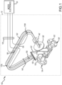
- FIG. 1 depicts an example flow meter 100.
- Flow meter 100 comprises a meter assembly 10 and a meter electronics 20.
- Meter assembly 10 responds to changes in a fluid flow.
- Meter electronics 20 receives raw data from meter assembly 10 via leads 102 and determines flow meter variables for the fluid under test, in addition to other information.
- Meter assembly 10 includes manifold 150, flanges 103 and 103', a pair of parallel flow tubes 130 and 130', driver 180, and a pair of velocity pick-off sensors 170L and 170R.
- Flow tubes 130 and 130' bend at two symmetrical locations along their length and are essentially parallel throughout their length.
- Brace bars 140 and 140' serve to define an axis about which each flow tube oscillates.
- Both flow tubes 130 and 130' are driven by driver 180 in opposite directions and at what is termed the first out-of-phase bending mode of the flow meter.
- This driver 180 may comprise any one of many well-known arrangements, such as a magnet mounted to flow tube 130' and an opposing coil mounted to flow tube 130 and through which an alternating current is passed for vibrating both flow tubes.
- a suitable driver voltage is applied by meter electronics 20 to driver 180.
- Meter electronics 20 provides the drive signal to driver 180 to vibrate flow tubes 130 and 130'.
- Meter electronics 20 receives the left and right velocity signals from velocity pick-off sensors 170L and 170R to compute the mass flow rate, volumetric rate, and/or density information for the flow passing through meter assembly 10.
- Flow meter 100 further comprises a case (not pictured) that protects the vibrating flow tubes.
- the case couples to the flow tube mounting blocks 120, 120'.
- the case may couple to other parts of flow meter 100.
- the case may couple to any other part of manifold 150, or flanges 103, 103'.
- flow meter 100 While the example of flow meter 100 includes two curved flow tubes, those of skill will understand that other configurations of flow meter 100 are possible.
- flow meter 100 may comprise one or any number of flow tubes, in straight or curved flow tube configurations.
- Installing flow meter 100 by attaching flanges 103, 103' to a process line can apply clamping forces in the axial direction to the flow tubes.
- Flow tubes 130, 130' are sensitive to axial stress, which can change the natural frequency of the flow tubes 130, 130'. Changing the natural frequency of flow tubes 130, 130' can interfere with flow meter 100 measurements, creating errors in the flow meter data.
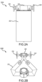
- FIG. 2A depicts flow meter 200A.
- Flow meter 200A includes a case 202, within which the flow tubes (not pictured) are positioned.
- a stainless-steel spacer 206 is positioned between flanges 204, 204' to maintain the spacing of the flanges, thereby preventing clamping forces from the flanges 204, 204' from affecting the flow tubes within case 202, which could increase the sensor error.
- FIG. 2B depicts a further prior flow meter 200B.
- Flow meter 200B includes a case 232 that surrounds the flow tubes (not pictured) and a casing 236 that provides an integrated manifold and spacer component between flanges 234, 234'.
- the casing 236 maintains the spacing between flanges 234, 234', thereby preventing the clamping strain from affecting the spacing of the flow tubes.
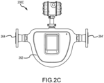
- FIG. 2C depicts a flow meter 200C that corresponds to a Micro Motion CMFS model flow meter.
- Flow meter 200C includes a case 262 that performs a spacer function between flanges 264, 264'.
- case 262 can transfer just enough of the axial clamping forces to the flow tubes to interfere with sensitive activities, such as meter calibration activities. Therefore, in order to verify meter accuracy, it is desirable to remove the axial clamping force on the flow tubes prior to meter testing, or prior to use of the meter.
- a flow meter coupling system to reduce axial stress on a flow meter is provided according to claim 1.
- a method for reducing axial stress when coupling a flow meter to a flow meter coupling is provided according to claim 8.
- the flow meter coupling system may further comprise a first connector member rigidly coupled to the first process fluid member and the first flow meter flange.
- the first process fluid member may be an inlet and the second process fluid member may be an outlet for a fluid.
- the flow meter coupling system may further comprise a flow meter alignment apparatus comprising at least one hanger for suspending the flow meter by a flow meter case.
- the first connector member may further comprise a first connector process fluid member collar configured to be coupled to the first process fluid member at a first process fluid member end of the first connector member, and a first connector flow meter interfacing member configured to be coupled to the first flow meter flange at a flow meter end of the first connector member.
- the first connector member may further comprise a flow reducer/increaser coupled to the first connector process fluid member collar at an end opposing the process fluid member end and coupled to the first connector flow meter interfacing member at an end opposing the flow meter end.
- the second connector member may further comprise the second connector rigid interfacing member, a second connector conduit member, and a second connector slidable coupler configured to sealably couple the second connector conduit member to the second process fluid member.
- FIGS. 3A -5B and the following description depict specific examples to teach those skilled in the art how to make and use the best mode of the Application. For the purpose of teaching inventive principles, some conventional aspects have been simplified or omitted. Those skilled in the art will appreciate variations from these examples that fall within the scope of the Application. Those skilled in the art will appreciate that the features described below may be combined in various ways to form multiple variations of the Application. As a result, the Application is not limited to the specific examples described below, but only by the claims.
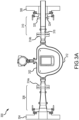
- Figure 3A depicts an example embodiment of flow meter coupling system 300, depicted as coupled to a flow meter 302.
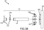
- Figure 3B depicts a detail of a second process fluid member 306 and a second connector member 310 of flow meter coupling system 300
- Figure 3C depicts a detail of a first connector member 308 and a first process fluid member 304 of flow meter coupling system 300.
- Flow meter coupling system 300 may be used to support normal process operations of flow meter 302. Flow meter coupling system 300 may also be used to support testing, characterizing, and/or calibration of flow meter 302. Flow meter coupling system 300 may be used to connect flow meter 302 to first process fluid member 304 and second process fluid member 306 in a manner that minimizes axial stress experienced at the flow meter 302, allowing a fluid to be flowed between first process fluid member 304 and second process fluid member 306 in either direction, through flow meter 302.
- flow meter 302 is coupled to first and second process fluid members 304, 306, which are head stocks. This is not intended to be limiting, however.
- flow meter coupling system 300 may be used to couple flow meter 302 to a process pipeline, and first and second process fluid members 304 and 306 may comprise a first coupling end of the process pipeline and a second coupling end of the process pipeline.
- flow meter 302 may comprise a dual, curved flow tube Coriolis flow meter like flow meters 100, 200A, 200B, or 200C. In further embodiments, however, flow meter 302 may comprise a Coriolis flow meter including any number of flow tubes in any possible configuration.
- Flow meter 302 comprises a first flange 314a and a second flange 314b.
- first flange 314a and second flange 314b may comprise any type of conduit coupler known to those of skill in the art.
- Flow meter 302 comprises a flow meter case 312. Much like case 262 depicted in Figure 2C , which provides a spacer function for the flow meter manifolds within case 262, case 312 also performs a spacer function between manifolds (not depicted) for flow meter 302.
- flow meter 302 may include any kind of flow meter case known to those of skill, including any variation of a flow meter case that does or does not provide a spacer function. In further embodiments, however, flow meter 302 may not comprise a case, but may comprise another structure to maintain the spacing between flow meter manifolds.
- Flow meter coupling system 300 comprises first process fluid member 304 and second process fluid member 306.
- first process fluid member 304 and second process fluid member 306 comprise inlets or outlets for fluid to be flowed through flow meter 302 during normal customer use of the meter, or during meter testing, calibration, characterization.
- First process fluid member 304 and second process fluid member 306 are stationary, meaning temporarily or permanently fixed.
- First process fluid member 304 and second process fluid member 306 fluidly connect flow meter 302 to one or more conduits or reservoirs of fluid to be measured by flow meter 302.
- First process fluid member 304 is configured to be coupled to the first flow meter flange 314a of the flow meter.
- Example first process fluid member 304 comprises a stationary vertical structure coupled to a band surrounding a fluid passageway.
- First flow meter flange 314a may be coupled to first process fluid member 304 using any type of coupling known to those of skill.
- Second process fluid member 306 is configured to be coupled to the second flow meter flange 314b.
- Example second process fluid member 306 also comprises a stationary vertical structure coupled to a band surrounding a fluid passageway to which second flow meter flange 314b may be coupled using any type of coupling known to those of skill.
- Flow meter coupling system 300 further comprises a second connector member 310.
- An exploded view of second connector member 310 is depicted in Figure 3B .
- Second connector member 310 couples the second flow meter flange 314b to the second process fluid member 306 by rigidly coupling at least one of the second flow meter flange 314b or the second process fluid member 306, and coupled to another of the second flow meter flange 314b or the second process fluid member 306 in a manner that provides substantially no axial stress.
- the second connector member 310 further comprises a second connector rigid interfacing member 316, a second connector conduit member 318, and a second connector slidable coupler 320 configured to sealably couple the second connector conduit member 318 to the second process fluid member 306.
- Second connector rigid interfacing member 316 rigidly couples the second connector conduit member 318 to the second flow meter flange 314b or the second process fluid member 306.
- second connector ridged interfacing member 316 comprises a second connector flange 316a and a second connector clamp 316b.
- the second connector flange 316a may comprise a surface with apertures that match up with apertures in second flow meter flange 314b, thereby allowing fasteners to couple the flanges together.
- Second connector clamp 316b may comprise any method of rigidly joining second connector flange 316a to second connector conduit member 318 known to those of skill.
- second connector clamp 316b may comprise a sanitary clamp.
- Second connector conduit member 318 comprises a conduit configured to be coupled rigidly at one end and in a manner that provides substantially no axial stress at a second end.
- second connector conduit member 318 is a straight conduit with a small flange feature at one end.
- Second connector slidable coupler 320 comprises a slidable coupler that provides a sealed connection between second process fluid member 306 and second connector conduit member 318.
- Slidable coupler 320 may be coupled to any axial position along second connector conduit member 318 where slidable coupler 320 may be fully seated. Because the axial position where slidable coupler 320 and second connector conduit member 318 couple together is not restricted, this may substantially reduce the axial stress between flow meter coupling system 300 and flow meter 302. In embodiments, slidable coupler 320 may substantially reduce the axial stress between flow meter coupling system 300 and flow meter 302 by 70%, 90% or 100% over prior art setups with dual flange couplings.
- Figure 3D provides a detail cutaway view of a second connector slidable coupler 320.
- second connector slidable coupler 320 further comprises seal seat 322 and an inflatable seal 324.
- Inflatable seal 324 is configured to be positioned within the seal seat 322, providing radial pressure to the second connector slidable coupler 320 to prevent fluid from leaking from second connector member 310.
- seal seat 322 comprises a flange seal seat component 322a with an annular recess coupled to a seal seat cover component 322b with an annular recess.
- the annular recesses of flange seal seat component 322a and seal seat cover component 322b face one another to form an inner annular void within seal seat 322.
- Inflatable seal 324 comprises an annular-shaped expandable membrane configured to nest inside the inner annular void within seal seat 322. Inflatable seal 324 can be expanded by adding pressurized fluid to the interior of inflatable seal 324 via an inlet/outlet valve (not depicted), such as, for example, a Schrader valve. In examples, inflatable seal 324 may comprise, for example, a rubber inner tube forming a 40-durometer seal.
- Second connector slidable coupler 320 further comprises a way to couple second connector slidable coupler 320 to one of second process fluid member 306 or second flow meter flange 314b.
- flange seal seat component 322a comprises one or more toggle levers 326b configured to engage hook-like elements 328b coupled to second process fluid member 306.
- Other methods of rigidly coupling second connector slidable coupler 320 to one of second process fluid member 306 or second flow meter flange 314b are also possible, as will be understood by those of skill.
- second connector rigid interfacing member 316 and second connector conduit member 318 may be formed from multiple sections that are coupled together. In further embodiments, however, second connector ridged interfacing member 316 and second connector conduit member 318 may be formed as an integrated part.
- second connector rigid interfacing member 316 is coupled to second flow meter flange 314b and second connector slidable coupler 320 is coupled to second process fluid member 306.
- second connector rigid interfacing member 316 may be coupled to second process fluid member 306 and second connector slidable coupler 320 may be coupled to second flow meter flange 314b.
- flow meter coupling system 300 further comprises a first connector member 308.
- First connector member 308 couples first process fluid member 304 to first flow meter flange 314a.
- first connector member 308 may rigidly couple first process fluid member 304 to first flow meter flange 314a.
- first connector member 308 may couple first process fluid member 304 to first flow meter flange 314a in a manner that provides substantially no axial stress.
- first connector member 308 may comprise a first connector process fluid member collar 328 and a first connector flow meter interfacing member 330.
- First connector process fluid member collar 328 may be configured to be coupled to first process fluid member 304 at a process fluid member end 332 of first connector member 308.
- first connector process fluid member collar 328 may comprise a first flange-like or annular member coupled to one or more toggle levers 326a configured to engage hook-like elements 328a coupled to first process fluid member 304 to create a seal.
- First connector flow meter interfacing member 330 may be configured to be coupled to first flow meter flange 314a at a flow meter end 334 of first connector member 308.
- first connector flow meter interfacing member 330 may comprise a flange configured to be coupled to first flow meter flange 314a.
- first connector member 308 may further comprise a flow reducer/increaser configured to increase or decrease the diameter of the flow between first process fluid member 304 or first connector process fluid member collar 328.
- Flow reducer/increaser 336 may be coupled to the first connector process fluid member collar 328 at an end opposing the process fluid member end 338 and coupled to first connector flow meter interfacing member 330 at an end opposing the flow meter end 340.
- flow reducer/increaser 336 may comprise a flange-like feature at opposing ends configured to allow flow reducer/increaser 336 to be coupled to first connector process fluid member collar 328 and first connector flow meter interfacing member 330.
- First connector process fluid member collar 328 and first connector flow meter interfacing member 330 may also comprise flange-like features configured to be coupled to flow reducer/increaser 336 via clamps 342a and 342b.
- clamps 342a and 342b may comprise sanitary clamps, or any type of clamps known to those of skill.
- first process fluid member 304 may comprise an inlet and second process fluid member 306 may comprise an outlet for a fluid. This may provide for less pressure on the second process fluid member 306 side of flow meter coupling system 300, thereby applying less pressure on inflatable seal 324.
- flow meter coupling system 300 may further comprise a flow meter alignment apparatus (not depicted).
- the flow meter alignment apparatus comprises any method of holding flow meter 302 within flow meter coupling system 300 to align first flow meter flange 314a and second flow meter flange 314b with first process fluid member 304 and second process fluid member 306.
- flow meter alignment apparatus may support flow meter 302 within flow meter coupling system 300 via one or more hangers, which may be used to suspend the flow meter by flow meter case 312.
- flow meter alignment apparatus may suspend flow meter case within flow meter coupling system 300 by supporting the section between first flow meter flange 314a and flow meter case 312, and the section between flow meter case 312 and second flow meter flange 314b.
- the example embodiment of one or more hangers is not intended to be limiting, however. Those of skill will readily understand that the flow meter alignment apparatus may comprise any manner to align and/or support flow meter 302 known to those of skill.
- Figure 4A depicts method 400A, in accordance with the invention.
- Method 400A is executed to reduce axial stress when coupling a flow meter comprising a flow meter case, a first flow meter flange, and a second flow meter flange, to a flow meter coupling system comprising a flow meter alignment apparatus, a first process fluid member, a second process fluid member, a first connector member, and a second connector member.
- Method 400A is used to couple flow meter 302 to flow meter coupling system 300.
- Method 400A begins with step 402.
- the flow meter case is positioned in the flow meter alignment apparatus of the flow meter coupling system.
- flow meter case 312 may be supported by two hangers positioned in the section between first flow meter flange 314a and flow meter case 312, and in the section between flow meter case 312 and second flow meter flange 314b, as described above.
- Step 404 the second connector member is rigidly coupled to at least one of the second flow meter flange or the second process fluid member using the second connector member.
- second connector member 310 may be coupled to second flow meter flange 314b, as described above and depicted in Figure 3A .
- step 404 may further comprise any combination of steps 410 and 412 of method 400B of Figure 4B .
- a second connector conduit member is coupled to a second connector rigid interfacing member.
- second connector conduit member 318 may be coupled to second connector rigid interfacing member 316, as described above and depicted in Figure 3B .
- the second connector rigid interfacing member is coupled to the at least one of the second flow meter flange or the second process fluid member.
- second connector rigid interfacing member 316 may be coupled to second flow meter flange 314b, as described above and depicted in Figure 3A .
- step 406 the second connector member is coupled to another of the second flow meter flange or the second process fluid member using the second connector member in a manner that provides substantially no axial stress.
- second connector member 310 may be coupled to second process fluid member 306, as described above and depicted in Figure 3A .
- step 406 may further comprise step 414 of method 400C of Figure 4C .
- a second connector slidable coupler is slidably and sealably coupled to the second connector conduit member.
- second connector slidable coupler 320 may be coupled to second connector conduit member 318, as described above.
- step 414 of method 400C may further comprise steps 416 and 418 of method 400C.
- a seal seat and an inflatable seal is threaded to position the seal seat and inflatable seal within the seal seat over the second connector conduit member.
- seal seat 322 and inflatable seal 324 may be threaded over second connector conduit member 318, as is best depicted in Figure 3D .
- the inflatable seal is inflated to provide radial pressure to the second connector conduit member.
- inflatable seal 324 may be pressurized, as described above.
- method 400A may further comprise step 408.
- the first process fluid member may be rigidly coupled to the first flow meter flange with the first connector member.
- first connector member 308 may be used to couple first process fluid member 304 rigidly to first flow meter flange 314a, as described above.
- step 408 is not intended to be limiting.
- first process fluid member 304 may alternatively be slidably coupled to first flow meter flange 314a similar to the way that second flow meter flange 314b is slidably connected to at least one of second flow meter flange 314b or second process fluid member 306.
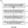
- step 408 may further comprise any combination of steps 420-426 of method 400D of Figure 4D .
- a first connector process fluid member collar may be coupled to the first process fluid member at a process fluid member end of the first connector member.
- first connector process fluid member collar 328 may be coupled to first process fluid member 304, as described above.
- a first connector flow meter interfacing member may be coupled to the first flow meter flange at a flow meter end of the first connector member.
- first connector flow meter interfacing member 330 may be coupled to first flow meter flange 314a, as descried above.
- a flow reducer/increaser may be coupled to the first connector process fluid member collar at an end opposing the process fluid member end.
- flow reducer/increaser 336 may be coupled to first connector process fluid member collar 328, as described above.
- the flow reducer/increaser may be coupled to the first connector flow meter interfacing member at an end opposing the flow meter end.
- flow reducer/increaser 336 may be coupled to first connector flow meter interfacing member 330, as described above.
- Figure 5A depicts axial clamping forces under a prior flow meter flow meter coupling system 500A including a rigidly coupled first process fluid member 502, a flow meter 504, and a rigidly coupled second process fluid member 506.
- the rigid coupling between flow meter 504 and second process fluid member 506 generates a clamping force F clamp and a reaction force R clamp in the axial direction of the flow meter conduit.
- the reaction force R clamp can place forces on flow meter 504 flow tubes, which may impact the flow meter data accuracy.
- FIG. 5B depicts clamping forces under a flow meter flow meter coupling system 500B according to an embodiment of the Application.
- flow meter coupling system 500B comprises a rigidly coupled first process fluid member 502, a flow meter 504, and a second process fluid member 508 coupled in a manner that provides substantially no axial stress.
- the connection between flow meter 504 and second process fluid member 506 comprises substantially no axial clamping force F clamp or reaction force R clamp .
- the second process fluid member 508 comprises radial sealing forces F seal from an inflatable seal in the radial direction of the flow meter conduit. Radial sealing forces F seal are much less likely to bend or place any strain on the flow tubes of flow meter 504, thereby maintaining the accuracy of flow meter 504.
Landscapes
- Physics & Mathematics (AREA)
- Fluid Mechanics (AREA)
- General Physics & Mathematics (AREA)
- Measuring Volume Flow (AREA)
Claims (13)
- Durchflussmesserkupplungssystem (300) zur Reduzierung der axialen Belastung eines Durchflussmessers (302), das einen ersten Durchflussmesserflansch (314a) und einen zweiten Durchflussmesserflansch (314b) umfasst,wobei das Durchflussmesserkupplungssystem (300) Folgendes umfasst:ein erstes Prozessfluidelement (304), das so konfiguriert ist, dass es mit dem ersten Durchflussmesserflansch (314a) des Durchflussmessers (302) gekuppelt werden kann;ein zweites Prozessfluidelement (306); undein erstes Anschlusselement (308) und ein zweites Anschlusselement (310), die so konfiguriert sind, dass sie starr mit mindestens einem von dem zweiten Durchflussmesserflansch (314b) oder dem zweiten Prozessfluidelement (306) gekuppelt sind undmit dem anderen von dem zweiten Durchflussmesserflansch (314b) oder dem zweiten Prozessfluidelement (306) gekuppelt sind, auf eine Weise, die im Wesentlichen keine axiale Spannung bereitstellt;wobei das zweite Anschlusselement (310) ferner Folgendes umfasst:ein zweites starres Anschlussverknüpfungselement (316) ;ein zweites Anschlussleitungselement (318);eine verschiebbare Kupplung (320), die dafür konfiguriert ist, das zweite Anschlussleitungselement (318) mit dem zweiten Prozessfluidelement (306) dichtend zu kuppeln;einen Dichtungssitz (322); undeine aufblasbare Dichtung (324), die so konfiguriert ist, dass sie innerhalb des Dichtungssitzes (322) positioniert werden kann und einen radialen Druck auf die verschiebbare Kupplung (320) des zweiten Anschlusselements ausübt.
- Durchflussmesserkupplungssystem (300) gemäß Anspruch 1,wobei das erste Anschlusselement (308) starr mit dem ersten Prozessfluidelement (304) und dem ersten Durchflussmesserflansch (314a) gekuppelt ist.
- Durchflussmesserkupplungssystem (300) nach einem der vorhergehenden Ansprüche,wobei das erste Prozessfluidelement (304) ein Einlass und das zweite Prozessfluidelement (306) ein Auslass für ein Fluid ist.
- Durchflussmesserkupplungssystem (300) nach einem der vorhergehenden Ansprüche,wobei das Durchflussmesserkupplungssystem (300) ferner eine Durchflussmesser-Ausrichtungsvorrichtung umfasst, die mindestens eine Aufhängung zum Aufhängen des Durchflussmessers (302) an einem Durchflussmessergehäuse (312) umfasst.
- Durchflussmesserkupplungssystem (300) nach einem der vorhergehenden Ansprüche,wobei das erste Anschlusselement (308) ferner Folgendes umfasst:einen ersten Prozessfluid-Anschlusselementkragen (328), der so konfiguriert ist, dass er mit dem ersten Prozessfluidelement (304) an einem ersten Prozessfluidelementende (332) des ersten Anschlusselements (308) gekuppelt werden kann; undein erstes Anschlussdurchflussmesser-Verknüpfungselement (330), das dafür konfiguriert ist, mit dem ersten Durchflussmesserflansch (314a) an einem Durchflussmesserende (334) des ersten Anschlusselements (308) gekuppelt zu werden.
- Durchflussmesserkupplungssystem (300) gemäß Anspruch 5,wobei das erste Anschlusselement (308) ferner Folgendes umfasst:
einen Durchflussreduzierer/-erhöher (336), der an einem Ende, das dem Ende des Prozessfluidelements (338) gegenüberliegt, mit dem Kragen (328) des ersten Anschlusselements des Prozessfluidelements gekuppelt ist undan einem Ende, das dem Ende (340) des Durchflussmessers gegenüberliegt, mit dem ersten Anschlussdurchflussmesser-Verknüpfungselement(330) gekuppelt ist. - Durchflussmesskupplungssystem (300) gemäß Anspruch 1,wobei das zweite starre Anschlussverknüpfungselement(316) mit dem zweiten Durchflussmesserflansch (314b) gekuppelt ist und die zweite verschiebbare Kupplung (320) mit dem zweiten Prozessfluidelement (306) gekuppelt ist.
- Verfahren zum Reduzieren der axialen Spannung beim Kuppeln eines Durchflussmessers (302) an ein Durchflussmesserkupplungssystem,wobei der Durchflussmesser ein Durchflussmessergehäuse (312), einen ersten Durchflussmesserflansch (314a) und einen zweiten Durchflussmesserflansch (314b) umfasst, unddas Durchflussmesserkupplungssystem (300) eine Durchflussmesser-Ausrichtungsvorrichtung, ein erstes Prozessfluidelement (304), ein zweites Prozessfluidelement (306), ein erstes Anschlusselement (308) und ein zweites Anschlusselement (310) umfasst,wobei das Verfahren Folgendes umfasst:Positionieren des Durchflussmessergehäuses (312) in der Durchflussmesser-Ausrichtungsvorrichtung des Durchflussmesserkupplungssystems (300);starres Kuppeln des zweiten Anschlusselements (310) mit mindestens einem von dem zweiten Durchflussmesserflansch (314b) oder dem zweiten Prozessfluidelement (306) unter Verwendung des zweiten Anschlusselements (310);Kuppeln eines zweiten Anschlussleitungselements (318) mit einem zweiten starren Anschlussverknüpfungselement (316) undKuppeln des zweiten starren Anschlussverknüpfungselements (316) mit mindestens einem von dem zweiten Durchflussmesserflansch (314b) oder dem zweiten Prozessfluidelement (306); undverschiebbares Kuppeln des zweiten Anschlusselements (310) mit dem zweiten Durchflussmesserflansch (314b) oder dem zweiten Prozessfluidelement (306) unter Verwendung des zweiten Anschlusselements (310) undverschiebbares Kuppeln einer zweiten verschiebbaren Anschlusskupplung (320) mit dem zweiten Anschlussleitungselement (318) auf eine Weise, die im Wesentlichen keine axiale Spannung bereitstellt;wobei das verschiebbare Kuppeln des zweiten verschiebbaren Anschlusskupplers (320) abdichtend an das zweite Anschlussleitungselement (318) ferner Folgendes umfasst:Aufschrauben eines Dichtungssitzes (322) und einer aufblasbaren Dichtung (324), die innerhalb des Dichtungssitzes (322) positioniert ist, auf das zweite Anschlussleitungselement (318); undAufblasen der aufblasbaren Dichtung (324), um einen radialen Druck auf das zweite Anschlussleitungselement (318) auszuüben.
- Verfahren nach Anspruch 8, wobei das Verfahren ferner Folgendes umfasst:
starres Kuppeln des ersten Prozessfluidelements (304) mit dem ersten Durchflussmesserflansch (314a) mit dem ersten Anschlusselement (308). - Verfahren nach einem der Ansprüche 8 bis 9,wobei das erste Prozessfluidelement (304) ein Einlass und das zweite Prozessfluidelement (306) ein Auslass für ein Fluid ist.
- Verfahren nach Anspruch 9,wobei das starre Kuppeln des ersten Prozessfluidelements (304) mit dem ersten Durchflussmesserflansch (314a) mit dem ersten Anschlusselement (308) ferner Folgendes umfasst.Kuppeln eines ersten Prozessfluid-Anschlusselementkragens (328) mit dem ersten Prozessfluidelement (304) an einem ersten Prozessfluidelementende (332) des ersten Verbindungselements (308); undKuppeln eines ersten Anschlussdurchflussmesser-Verknüpfungselements (330) mit dem ersten Durchflussmesserflansch (314a) an einem Durchflussmesserende (334) des ersten Anschlusselements (308) .
- Verfahren nach Anspruch 11,wobei das starre Kuppeln des ersten Prozessfluidelements (304) mit dem ersten Durchflussmesserflansch (314a) mit dem ersten Anschlusselement (308) ferner Folgendes umfasst.Kuppeln eines Durchflussreduzierers/-erhöhers (336) an den ersten Prozessfluid-Anschlusselementkragen (328) an einem Ende, das dem Ende des Prozessfluidelements (338) gegenüberliegt; undKuppeln des Durchflussreduzierers/-erhöhers (336) an das erste Anschlussdurchflussmesser-Verknüpfungselement (330) an einem Ende, das dem Ende des Durchflussmessers (340) gegenüberliegt.
- Verfahren nach einem der Ansprüche 8 bis 12,wobei das zweite starre Anschlussverknüpfungselement(316) mit dem zweiten Durchflussmesserflansch (314b) gekuppelt ist und die zweite verschiebbare Kupplung (320) mit dem zweiten Prozessfluidelement (306) gekuppelt ist.
Applications Claiming Priority (1)
| Application Number | Priority Date | Filing Date | Title |
|---|---|---|---|
| PCT/US2020/021240 WO2021177967A1 (en) | 2020-03-05 | 2020-03-05 | Flow meter coupling system |
Publications (2)
| Publication Number | Publication Date |
|---|---|
| EP4115154A1 EP4115154A1 (de) | 2023-01-11 |
| EP4115154B1 true EP4115154B1 (de) | 2025-01-01 |
Family
ID=70108175
Family Applications (1)
| Application Number | Title | Priority Date | Filing Date |
|---|---|---|---|
| EP20716139.9A Active EP4115154B1 (de) | 2020-03-05 | 2020-03-05 | Durchflussmesserkupplungssystem |
Country Status (5)
| Country | Link |
|---|---|
| US (1) | US12196594B2 (de) |
| EP (1) | EP4115154B1 (de) |
| JP (1) | JP7480330B2 (de) |
| CN (1) | CN115244366A (de) |
| WO (1) | WO2021177967A1 (de) |
Family Cites Families (78)
| Publication number | Priority date | Publication date | Assignee | Title |
|---|---|---|---|---|
| US1997845A (en) * | 1934-04-25 | 1935-04-16 | Adams Brothers Inc Ltd | Meter coupling |
| US3527245A (en) * | 1968-02-15 | 1970-09-08 | Marcel Lamontagne | Universal gas meter installation |
| DE2409074A1 (de) | 1974-02-26 | 1975-09-04 | Spitzer Silo Fahrzeugwerk Kg | Verschluss fuer die einfuelloeffnung eines silobehaelters |
| US4342336A (en) * | 1979-10-03 | 1982-08-03 | Satterthwaite J Glenn | Double-acting inflatable seal |
| DE3143866A1 (de) | 1981-11-05 | 1983-05-11 | Howaldtswerke-Deutsche Werft Ag Hamburg Und Kiel, 2300 Kiel | Abdichtungsanordnung mit einem radialgleitring |
| US4570913A (en) | 1984-01-11 | 1986-02-18 | Production Equipment & Engineering Co. | Clamping apparatus for truss manufacturing equipment |
| US4549751A (en) * | 1984-02-03 | 1985-10-29 | Grove Jr Leslie W | Universal support for meters |
| US4691727A (en) * | 1985-11-04 | 1987-09-08 | A. Y. Mcdonald Manufacturing Co. | Flow conditioning device resetter assembly |
| US5209266A (en) * | 1990-12-11 | 1993-05-11 | Cherne Industries Incorporated | High pressure inflatable plug device |
| US5373745A (en) | 1991-02-05 | 1994-12-20 | Direct Measurement Corporation | Single path radial mode Coriolis mass flow rate meter |
| US5145214A (en) * | 1991-07-15 | 1992-09-08 | Mitchell Hunt | Adjustable meter setter |
| US5778919A (en) | 1993-12-30 | 1998-07-14 | Custom Service Laboratories Of N.J., Inc. | Pipeline flow stopper with dual shafts |
| JPH07270208A (ja) * | 1994-03-31 | 1995-10-20 | Tokico Ltd | 振動式測定装置 |
| AU3491595A (en) | 1994-09-08 | 1996-03-29 | Smith Meter Inc. | Mass flowmeter and conduit assembly |
| US5632632A (en) * | 1994-09-29 | 1997-05-27 | Rosemount Inc. | Flowmeter alignment device |
| JPH09113330A (ja) * | 1995-10-19 | 1997-05-02 | Tokico Ltd | 振動式測定装置 |
| JP3387767B2 (ja) * | 1997-02-13 | 2003-03-17 | 株式会社オーバル | 高温型コリオリ流量計 |
| DE19725805A1 (de) | 1997-06-18 | 1998-12-24 | Basf Ag | Verfahren und Vorrichtung zur Messung des Flüssigkeitsdurchsatzes in einem Kanal |
| US5909904A (en) * | 1998-07-24 | 1999-06-08 | Shea Technology | Flange joint assemblies |
| FR2786863B1 (fr) * | 1998-12-03 | 2001-02-02 | Philippe Henault | Dispositif de maintien entre deux troncons d'une conduite, d'un appareil de mesure d'une caracteristique d'un fluide |
| JP3224788B2 (ja) * | 1999-03-02 | 2001-11-05 | 株式会社オーバル | 直管シングルチューブコリオリ流量計 |
| GB9927137D0 (en) * | 1999-11-16 | 2000-01-12 | Alpha Thames Limited | Two-parter connector for fluid carrying conduits |
| JP2001198754A (ja) | 2000-01-17 | 2001-07-24 | Pascal Kk | ワーク固定用クランプシステム |
| GB2375401A (en) * | 2001-05-03 | 2002-11-13 | Endress & Hauser Ltd | A flow meter incorporating thermal loss sensors and an installation adapter to provide known flow conditions upstream of the flow meter |
| US6782333B2 (en) * | 2002-05-31 | 2004-08-24 | Micro Motion, Inc. | Meter calibration system and apparatus |
| JP2004239923A (ja) * | 2004-05-28 | 2004-08-26 | Oval Corp | コリオリ流量計 |
| US20060022466A1 (en) * | 2004-06-23 | 2006-02-02 | Kim Sand | Flange adapter |
| WO2006019923A2 (en) * | 2004-07-15 | 2006-02-23 | Pdc Facilities, Inc. | Liner for a flow meter |
| US20060070437A1 (en) * | 2004-09-30 | 2006-04-06 | Rosemount Inc. | Gasket arrangement for sanitary process flow meter |
| US9891089B2 (en) * | 2013-04-15 | 2018-02-13 | OW Investors, LLC. | Modular fluid meter test bench |
| US8220839B2 (en) * | 2005-03-09 | 2012-07-17 | Hydrocom Pty Ltd | Pipe insert |
| JP4183090B2 (ja) * | 2005-03-29 | 2008-11-19 | 株式会社オーバル | コリオリ流量計の上下流配管構造 |
| US7819139B2 (en) * | 2005-07-14 | 2010-10-26 | Pdc Facilities, Inc. | Liner for a flow meter |
| JP3877174B1 (ja) | 2005-09-13 | 2007-02-07 | 株式会社オーバル | 弾性連結部材及び台座を有する三次モード振動の直管式コリオリ流量計 |
| WO2007124743A1 (en) | 2006-04-28 | 2007-11-08 | Aeromatic-Fielder Ag | Inflatable seal, set of flange parts and container comprising such seal, and method of manufacturing such seal |
| US8302496B2 (en) * | 2006-06-03 | 2012-11-06 | Eldon James Corporation | Universal sensor fitting for process applications |
| RU2414686C2 (ru) * | 2006-07-21 | 2011-03-20 | Эндресс+Хаузер Флоутек Аг | Измерительная система для среды, протекающей в технологическом трубопроводе |
| DE102007003614A1 (de) * | 2006-07-26 | 2008-01-31 | Endress + Hauser Flowtec Ag | Vorrichtung zum Messen des Volumen- oder Massestroms eines Mediums in einer Rohrleitung |
| US8240718B2 (en) * | 2006-07-28 | 2012-08-14 | Hitco, Inc. | Sanitary quick connector |
| JP2008275682A (ja) | 2007-04-25 | 2008-11-13 | Bridgestone Corp | 帯電ローラ |
| GB0712271D0 (en) * | 2007-06-22 | 2007-08-01 | Beele Eng Bv | Method and sealing system for sealing an annular space between a rigid conduit and a pipe, tube or duct extending through the conduit |
| CN201083303Y (zh) * | 2007-07-16 | 2008-07-09 | 郭建勋 | 柔性管道连接修补器 |
| US8480883B2 (en) * | 2007-07-18 | 2013-07-09 | Dlp Limited | Pipe coupling with integrated filter and flow detector |
| US9581486B2 (en) | 2008-05-29 | 2017-02-28 | Wfms, Inc. | Method and apparatus for a bidirectional meter proving system |
| US8161812B1 (en) * | 2008-12-19 | 2012-04-24 | The Gas Measurement Group, Inc. | High pressure fluid meter |
| CN201680884U (zh) | 2010-05-21 | 2010-12-22 | 北京中盛华旭电子科技有限公司 | 全截流装置 |
| CN201739673U (zh) * | 2010-06-02 | 2011-02-09 | 郑州市兆龙阀门有限公司 | 一种承盘伸缩器 |
| US8342200B1 (en) * | 2010-07-20 | 2013-01-01 | William Payne | Meter yoke vise |
| US20150209787A1 (en) * | 2010-10-29 | 2015-07-30 | Thermo Finnigan Llc | Apparatus and Method for Coupling Tubing to Chromatographihc Column |
| TWI525184B (zh) | 2011-12-16 | 2016-03-11 | 拜歐菲樂Ip有限責任公司 | 低溫注射組成物,用於低溫調節導管中流量之系統及方法 |
| CN102435245B (zh) * | 2012-01-06 | 2014-01-15 | 兰州海默科技股份有限公司 | 一种蒸汽流量计量装置及计量方法 |
| US9329017B2 (en) * | 2012-03-20 | 2016-05-03 | Micro Motion, Inc. | Alignment tool |
| US10012333B2 (en) * | 2012-06-06 | 2018-07-03 | Langdon Incorporated | Fluid conditioning devices and assemblies |
| US9354095B2 (en) * | 2012-10-02 | 2016-05-31 | Honeywell International Inc. | Modular flow sensor |
| CN103835277B (zh) | 2012-11-22 | 2016-02-17 | 同济大学 | 一种用于软土地层的气胀式多点位移计锚头 |
| DE102013200765A1 (de) * | 2013-01-18 | 2014-07-24 | Pfeiffer Vacuum Gmbh | Verbindungsvorrichtung |
| US9151648B2 (en) * | 2013-03-15 | 2015-10-06 | Dieterich Standard, Inc. | Process variable measurement using primary element connection platform |
| CN203380816U (zh) | 2013-08-12 | 2014-01-08 | 贵州长征电力设备有限公司 | 一种法兰快速夹紧装置 |
| TWM481995U (zh) * | 2014-03-13 | 2014-07-11 | Stairs Ind Co Ltd | 泵浦之進出水口法蘭結構(一) |
| US9459126B2 (en) * | 2014-04-16 | 2016-10-04 | Dieterich Standard, Inc. | Flow meter |
| DE102014114941A1 (de) * | 2014-10-15 | 2016-04-21 | Endress + Hauser Gmbh + Co. Kg | Hybrid-Flansch |
| US10081039B2 (en) * | 2014-12-18 | 2018-09-25 | Dieterich Standard, Inc. | Rodable pressure coupling |
| US9664318B2 (en) * | 2014-12-30 | 2017-05-30 | Quick Fitting, Inc. | Fitting adapter with integrated mounting assembly and device |
| US9927277B1 (en) * | 2015-03-16 | 2018-03-27 | John C. Kupferle Foundry Company | Plastic body meter resetter |
| US9671270B2 (en) * | 2015-07-30 | 2017-06-06 | Daniel Measurement And Control, Inc. | Flow meter having electronic mount bracket assembly |
| WO2018013857A1 (en) * | 2016-07-13 | 2018-01-18 | Rain Bird Corporation | Flow sensor |
| GB2555003B (en) * | 2016-09-23 | 2022-07-06 | Blue White Ind Ltd | Flow sensor devices and systems |
| US10132664B2 (en) * | 2016-10-27 | 2018-11-20 | Daniel Measurement And Control, Inc. | Adjustable flow meter system |
| US10386218B2 (en) * | 2016-11-22 | 2019-08-20 | Rota Yokogawa Gmbh & Co. Kg | Temperature measurement system for measuring the temperature of a tube and flowmeter comprising the temperature measurement system |
| US11060637B2 (en) * | 2016-12-01 | 2021-07-13 | Ckd Corporation | Coupling member, fluid-device connecting jig, and fluid-device connecting structure |
| US9880032B1 (en) * | 2017-06-20 | 2018-01-30 | Johnathan W. Linney | Modular removable flow metering assembly with cone shaped differential pressure producer in a compact fluid conduit |
| CN207379560U (zh) | 2017-10-19 | 2018-05-18 | 宁夏绿叶信息科技有限公司 | 一种超声波流量计 |
| DE102018001778A1 (de) * | 2018-03-06 | 2019-09-12 | Rota Yokogawa Gmbh & Co. Kg | Massendurchfluss- und Dichtemesser nach dem Coriolis-Prinzip mit geringer Druckabhängigkeit und Verfahren zur Herstellung |
| EP3769051B1 (de) * | 2018-03-22 | 2023-10-04 | GE Infrastructure Sensing, LLC | System zur online-installation einer ultraschalldampfmessvorrichtung |
| JP7455809B2 (ja) * | 2018-07-27 | 2024-03-26 | アイエムティー メディカル アクチエンゲゼルシャフト | 呼吸流量センサ |
| WO2021031217A1 (zh) * | 2019-08-22 | 2021-02-25 | 无锡洋湃科技有限公司 | 一种基于科氏力质量流量计的湿气流量计量方法及其装置 |
| RU2754656C1 (ru) * | 2020-04-30 | 2021-09-06 | Шлюмберже Текнолоджи Б.В. | Способ и система измерения расходов многофазного и/или многокомпонентного флюида, добываемого из нефтегазовой скважины |
| DE102021104631A1 (de) * | 2021-02-26 | 2022-09-01 | Endress+Hauser Flowtec Ag | Meßgerät |
-
2020
- 2020-03-05 EP EP20716139.9A patent/EP4115154B1/de active Active
- 2020-03-05 JP JP2022552925A patent/JP7480330B2/ja active Active
- 2020-03-05 US US17/907,903 patent/US12196594B2/en active Active
- 2020-03-05 WO PCT/US2020/021240 patent/WO2021177967A1/en not_active Ceased
- 2020-03-05 CN CN202080097924.1A patent/CN115244366A/zh active Pending
Also Published As
| Publication number | Publication date |
|---|---|
| WO2021177967A1 (en) | 2021-09-10 |
| CN115244366A (zh) | 2022-10-25 |
| US20230145225A1 (en) | 2023-05-11 |
| US12196594B2 (en) | 2025-01-14 |
| EP4115154A1 (de) | 2023-01-11 |
| JP2023517874A (ja) | 2023-04-27 |
| JP7480330B2 (ja) | 2024-05-09 |
Similar Documents
| Publication | Publication Date | Title |
|---|---|---|
| US4193420A (en) | Differential pressure transducer process mounting support and manifold | |
| EP0867694B1 (de) | Coriolis-Massendurchflussmesser | |
| CN1116588C (zh) | 双环路型科里奥利质量流量计 | |
| US4920626A (en) | Stabilized connector flange for interconnecting an instrument manifold with an orifice plate assembly | |
| CN101946163B (zh) | 带有改进的平衡系统的科里奥利流量计 | |
| US4974308A (en) | Method for interconnecting an instrument manifold with an orifice plate assembly | |
| CN109297557A (zh) | 使用通用流量技术连接平台的过程变量测量 | |
| EP2898299B1 (de) | Vibrierende sensoranordnung mit einteiliger leitungshalterung | |
| EP4115154B1 (de) | Durchflussmesserkupplungssystem | |
| HK40076809A (en) | Flow meter coupling system | |
| EP3245487B1 (de) | Ultraschall-durchflussmesser mit laufzeitdifferenzmessung, wandler, durchflussmesser und verfahren | |
| US4513625A (en) | Flow meter and densitometer apparatus and method of operation | |
| US4986135A (en) | Apparatus and method for measuring fluid flow and density | |
| JPH04339220A (ja) | コリオリ式質量流量計 | |
| CA2567284C (en) | Restriction flowmeter | |
| CN119492477B (zh) | 压差传感器和压差检测装置 | |
| JPS6370121A (ja) | 流量・圧力測定装置 | |
| JPH01136026A (ja) | 振動式測定装置 | |
| JPH05215584A (ja) | 振動式測定装置 | |
| JP2006017520A (ja) | 振動式測定装置 | |
| JP2001108501A (ja) | コリオリ質量流量計 | |
| JP3375804B2 (ja) | リモートシールダイアフラム型差圧発信器の固定構造 | |
| JPH04264217A (ja) | 質量流量計測システム | |
| HK1211692B (en) | Vibrating sensor assembly with a one-piece conduit mount | |
| JPH0749982B2 (ja) | 質量流量計 |
Legal Events
| Date | Code | Title | Description |
|---|---|---|---|
| STAA | Information on the status of an ep patent application or granted ep patent |
Free format text: STATUS: UNKNOWN |
|
| STAA | Information on the status of an ep patent application or granted ep patent |
Free format text: STATUS: THE INTERNATIONAL PUBLICATION HAS BEEN MADE |
|
| PUAI | Public reference made under article 153(3) epc to a published international application that has entered the european phase |
Free format text: ORIGINAL CODE: 0009012 |
|
| STAA | Information on the status of an ep patent application or granted ep patent |
Free format text: STATUS: REQUEST FOR EXAMINATION WAS MADE |
|
| 17P | Request for examination filed |
Effective date: 20220922 |
|
| AK | Designated contracting states |
Kind code of ref document: A1 Designated state(s): AL AT BE BG CH CY CZ DE DK EE ES FI FR GB GR HR HU IE IS IT LI LT LU LV MC MK MT NL NO PL PT RO RS SE SI SK SM TR |
|
| DAV | Request for validation of the european patent (deleted) | ||
| DAX | Request for extension of the european patent (deleted) | ||
| P01 | Opt-out of the competence of the unified patent court (upc) registered |
Effective date: 20230526 |
|
| GRAP | Despatch of communication of intention to grant a patent |
Free format text: ORIGINAL CODE: EPIDOSNIGR1 |
|
| STAA | Information on the status of an ep patent application or granted ep patent |
Free format text: STATUS: GRANT OF PATENT IS INTENDED |
|
| INTG | Intention to grant announced |
Effective date: 20240807 |
|
| GRAS | Grant fee paid |
Free format text: ORIGINAL CODE: EPIDOSNIGR3 |
|
| GRAA | (expected) grant |
Free format text: ORIGINAL CODE: 0009210 |
|
| STAA | Information on the status of an ep patent application or granted ep patent |
Free format text: STATUS: THE PATENT HAS BEEN GRANTED |
|
| AK | Designated contracting states |
Kind code of ref document: B1 Designated state(s): AL AT BE BG CH CY CZ DE DK EE ES FI FR GB GR HR HU IE IS IT LI LT LU LV MC MK MT NL NO PL PT RO RS SE SI SK SM TR |
|
| REG | Reference to a national code |
Ref country code: GB Ref legal event code: FG4D |
|
| REG | Reference to a national code |
Ref country code: DE Ref legal event code: R096 Ref document number: 602020044023 Country of ref document: DE |
|
| REG | Reference to a national code |
Ref country code: CH Ref legal event code: EP |
|
| REG | Reference to a national code |
Ref country code: IE Ref legal event code: FG4D |
|
| PGFP | Annual fee paid to national office [announced via postgrant information from national office to epo] |
Ref country code: DE Payment date: 20250218 Year of fee payment: 6 |
|
| REG | Reference to a national code |
Ref country code: LT Ref legal event code: MG9D |
|
| PGFP | Annual fee paid to national office [announced via postgrant information from national office to epo] |
Ref country code: GB Payment date: 20250221 Year of fee payment: 6 |
|
| REG | Reference to a national code |
Ref country code: NL Ref legal event code: MP Effective date: 20250101 |
|
| REG | Reference to a national code |
Ref country code: AT Ref legal event code: MK05 Ref document number: 1756660 Country of ref document: AT Kind code of ref document: T Effective date: 20250101 |
|
| PG25 | Lapsed in a contracting state [announced via postgrant information from national office to epo] |
Ref country code: NL Free format text: LAPSE BECAUSE OF FAILURE TO SUBMIT A TRANSLATION OF THE DESCRIPTION OR TO PAY THE FEE WITHIN THE PRESCRIBED TIME-LIMIT Effective date: 20250101 |
|
| PG25 | Lapsed in a contracting state [announced via postgrant information from national office to epo] |
Ref country code: FI Free format text: LAPSE BECAUSE OF FAILURE TO SUBMIT A TRANSLATION OF THE DESCRIPTION OR TO PAY THE FEE WITHIN THE PRESCRIBED TIME-LIMIT Effective date: 20250101 |
|
| PG25 | Lapsed in a contracting state [announced via postgrant information from national office to epo] |
Ref country code: PL Free format text: LAPSE BECAUSE OF FAILURE TO SUBMIT A TRANSLATION OF THE DESCRIPTION OR TO PAY THE FEE WITHIN THE PRESCRIBED TIME-LIMIT Effective date: 20250101 |
|
| PG25 | Lapsed in a contracting state [announced via postgrant information from national office to epo] |
Ref country code: ES Free format text: LAPSE BECAUSE OF FAILURE TO SUBMIT A TRANSLATION OF THE DESCRIPTION OR TO PAY THE FEE WITHIN THE PRESCRIBED TIME-LIMIT Effective date: 20250101 |
|
| PG25 | Lapsed in a contracting state [announced via postgrant information from national office to epo] |
Ref country code: IS Free format text: LAPSE BECAUSE OF FAILURE TO SUBMIT A TRANSLATION OF THE DESCRIPTION OR TO PAY THE FEE WITHIN THE PRESCRIBED TIME-LIMIT Effective date: 20250501 Ref country code: NO Free format text: LAPSE BECAUSE OF FAILURE TO SUBMIT A TRANSLATION OF THE DESCRIPTION OR TO PAY THE FEE WITHIN THE PRESCRIBED TIME-LIMIT Effective date: 20250401 |
|
| PG25 | Lapsed in a contracting state [announced via postgrant information from national office to epo] |
Ref country code: HR Free format text: LAPSE BECAUSE OF FAILURE TO SUBMIT A TRANSLATION OF THE DESCRIPTION OR TO PAY THE FEE WITHIN THE PRESCRIBED TIME-LIMIT Effective date: 20250101 |
|
| PG25 | Lapsed in a contracting state [announced via postgrant information from national office to epo] |
Ref country code: LV Free format text: LAPSE BECAUSE OF FAILURE TO SUBMIT A TRANSLATION OF THE DESCRIPTION OR TO PAY THE FEE WITHIN THE PRESCRIBED TIME-LIMIT Effective date: 20250101 Ref country code: PT Free format text: LAPSE BECAUSE OF FAILURE TO SUBMIT A TRANSLATION OF THE DESCRIPTION OR TO PAY THE FEE WITHIN THE PRESCRIBED TIME-LIMIT Effective date: 20250502 |
|
| PG25 | Lapsed in a contracting state [announced via postgrant information from national office to epo] |
Ref country code: GR Free format text: LAPSE BECAUSE OF FAILURE TO SUBMIT A TRANSLATION OF THE DESCRIPTION OR TO PAY THE FEE WITHIN THE PRESCRIBED TIME-LIMIT Effective date: 20250402 Ref country code: BG Free format text: LAPSE BECAUSE OF FAILURE TO SUBMIT A TRANSLATION OF THE DESCRIPTION OR TO PAY THE FEE WITHIN THE PRESCRIBED TIME-LIMIT Effective date: 20250101 |
|
| PGFP | Annual fee paid to national office [announced via postgrant information from national office to epo] |
Ref country code: CH Payment date: 20250401 Year of fee payment: 6 |
|
| PG25 | Lapsed in a contracting state [announced via postgrant information from national office to epo] |
Ref country code: AT Free format text: LAPSE BECAUSE OF FAILURE TO SUBMIT A TRANSLATION OF THE DESCRIPTION OR TO PAY THE FEE WITHIN THE PRESCRIBED TIME-LIMIT Effective date: 20250101 |
|
| PG25 | Lapsed in a contracting state [announced via postgrant information from national office to epo] |
Ref country code: CZ Free format text: LAPSE BECAUSE OF FAILURE TO SUBMIT A TRANSLATION OF THE DESCRIPTION OR TO PAY THE FEE WITHIN THE PRESCRIBED TIME-LIMIT Effective date: 20250101 |
|
| PG25 | Lapsed in a contracting state [announced via postgrant information from national office to epo] |
Ref country code: SE Free format text: LAPSE BECAUSE OF FAILURE TO SUBMIT A TRANSLATION OF THE DESCRIPTION OR TO PAY THE FEE WITHIN THE PRESCRIBED TIME-LIMIT Effective date: 20250101 |
|
| REG | Reference to a national code |
Ref country code: DE Ref legal event code: R097 Ref document number: 602020044023 Country of ref document: DE |
|
| PG25 | Lapsed in a contracting state [announced via postgrant information from national office to epo] |
Ref country code: SM Free format text: LAPSE BECAUSE OF FAILURE TO SUBMIT A TRANSLATION OF THE DESCRIPTION OR TO PAY THE FEE WITHIN THE PRESCRIBED TIME-LIMIT Effective date: 20250101 |
|
| PG25 | Lapsed in a contracting state [announced via postgrant information from national office to epo] |
Ref country code: DK Free format text: LAPSE BECAUSE OF FAILURE TO SUBMIT A TRANSLATION OF THE DESCRIPTION OR TO PAY THE FEE WITHIN THE PRESCRIBED TIME-LIMIT Effective date: 20250101 |
|
| PG25 | Lapsed in a contracting state [announced via postgrant information from national office to epo] |
Ref country code: MC Free format text: LAPSE BECAUSE OF FAILURE TO SUBMIT A TRANSLATION OF THE DESCRIPTION OR TO PAY THE FEE WITHIN THE PRESCRIBED TIME-LIMIT Effective date: 20250101 |
|
| PG25 | Lapsed in a contracting state [announced via postgrant information from national office to epo] |
Ref country code: IT Free format text: LAPSE BECAUSE OF FAILURE TO SUBMIT A TRANSLATION OF THE DESCRIPTION OR TO PAY THE FEE WITHIN THE PRESCRIBED TIME-LIMIT Effective date: 20250101 |
|
| PG25 | Lapsed in a contracting state [announced via postgrant information from national office to epo] |
Ref country code: EE Free format text: LAPSE BECAUSE OF FAILURE TO SUBMIT A TRANSLATION OF THE DESCRIPTION OR TO PAY THE FEE WITHIN THE PRESCRIBED TIME-LIMIT Effective date: 20250101 |
|
| PG25 | Lapsed in a contracting state [announced via postgrant information from national office to epo] |
Ref country code: RO Free format text: LAPSE BECAUSE OF FAILURE TO SUBMIT A TRANSLATION OF THE DESCRIPTION OR TO PAY THE FEE WITHIN THE PRESCRIBED TIME-LIMIT Effective date: 20250101 |
|
| PG25 | Lapsed in a contracting state [announced via postgrant information from national office to epo] |
Ref country code: SK Free format text: LAPSE BECAUSE OF FAILURE TO SUBMIT A TRANSLATION OF THE DESCRIPTION OR TO PAY THE FEE WITHIN THE PRESCRIBED TIME-LIMIT Effective date: 20250101 |
|
| RAP4 | Party data changed (patent owner data changed or rights of a patent transferred) |
Owner name: MICRO MOTION, INC. |
|
| PLBE | No opposition filed within time limit |
Free format text: ORIGINAL CODE: 0009261 |
|
| STAA | Information on the status of an ep patent application or granted ep patent |
Free format text: STATUS: NO OPPOSITION FILED WITHIN TIME LIMIT |
|
| PG25 | Lapsed in a contracting state [announced via postgrant information from national office to epo] |
Ref country code: LU Free format text: LAPSE BECAUSE OF NON-PAYMENT OF DUE FEES Effective date: 20250305 |
|
| 26N | No opposition filed |
Effective date: 20251002 |
|
| REG | Reference to a national code |
Ref country code: BE Ref legal event code: MM Effective date: 20250331 |
|
| PG25 | Lapsed in a contracting state [announced via postgrant information from national office to epo] |
Ref country code: FR Free format text: LAPSE BECAUSE OF NON-PAYMENT OF DUE FEES Effective date: 20250331 |
|
| PG25 | Lapsed in a contracting state [announced via postgrant information from national office to epo] |
Ref country code: BE Free format text: LAPSE BECAUSE OF NON-PAYMENT OF DUE FEES Effective date: 20250331 |
|
| PG25 | Lapsed in a contracting state [announced via postgrant information from national office to epo] |
Ref country code: IE Free format text: LAPSE BECAUSE OF NON-PAYMENT OF DUE FEES Effective date: 20250305 |