EP4113073A1 - Vorrichtung und verfahren zum wiegen von gefüllten kapseln - Google Patents
Vorrichtung und verfahren zum wiegen von gefüllten kapseln Download PDFInfo
- Publication number
- EP4113073A1 EP4113073A1 EP21182828.0A EP21182828A EP4113073A1 EP 4113073 A1 EP4113073 A1 EP 4113073A1 EP 21182828 A EP21182828 A EP 21182828A EP 4113073 A1 EP4113073 A1 EP 4113073A1
- Authority
- EP
- European Patent Office
- Prior art keywords
- capsule
- weighing
- receiving section
- movement
- receptacle
- Prior art date
- Legal status (The legal status is an assumption and is not a legal conclusion. Google has not performed a legal analysis and makes no representation as to the accuracy of the status listed.)
- Granted
Links
Images
Classifications
-
- G—PHYSICS
- G01—MEASURING; TESTING
- G01G—WEIGHING
- G01G17/00—Apparatus for or methods of weighing material of special form or property
-
- G—PHYSICS
- G01—MEASURING; TESTING
- G01G—WEIGHING
- G01G13/00—Weighing apparatus with automatic feed or discharge for weighing-out batches of material
- G01G13/02—Means for automatically loading weigh pans or other receptacles, e.g. disposable containers, under control of the weighing mechanism
-
- G—PHYSICS
- G01—MEASURING; TESTING
- G01G—WEIGHING
- G01G15/00—Arrangements for check-weighing of materials dispensed into removable containers
-
- G—PHYSICS
- G01—MEASURING; TESTING
- G01G—WEIGHING
- G01G21/00—Details of weighing apparatus
-
- G—PHYSICS
- G01—MEASURING; TESTING
- G01G—WEIGHING
- G01G21/00—Details of weighing apparatus
- G01G21/22—Weigh pans or other weighing receptacles; Weighing platforms
-
- A—HUMAN NECESSITIES
- A61—MEDICAL OR VETERINARY SCIENCE; HYGIENE
- A61J—CONTAINERS SPECIALLY ADAPTED FOR MEDICAL OR PHARMACEUTICAL PURPOSES; DEVICES OR METHODS SPECIALLY ADAPTED FOR BRINGING PHARMACEUTICAL PRODUCTS INTO PARTICULAR PHYSICAL OR ADMINISTERING FORMS; DEVICES FOR ADMINISTERING FOOD OR MEDICINES ORALLY; BABY COMFORTERS; DEVICES FOR RECEIVING SPITTLE
- A61J2200/00—General characteristics or adaptations
- A61J2200/70—Device provided with specific sensor or indicating means
- A61J2200/74—Device provided with specific sensor or indicating means for weight
-
- A—HUMAN NECESSITIES
- A61—MEDICAL OR VETERINARY SCIENCE; HYGIENE
- A61J—CONTAINERS SPECIALLY ADAPTED FOR MEDICAL OR PHARMACEUTICAL PURPOSES; DEVICES OR METHODS SPECIALLY ADAPTED FOR BRINGING PHARMACEUTICAL PRODUCTS INTO PARTICULAR PHYSICAL OR ADMINISTERING FORMS; DEVICES FOR ADMINISTERING FOOD OR MEDICINES ORALLY; BABY COMFORTERS; DEVICES FOR RECEIVING SPITTLE
- A61J3/00—Devices or methods specially adapted for bringing pharmaceutical products into particular physical or administering forms
- A61J3/07—Devices or methods specially adapted for bringing pharmaceutical products into particular physical or administering forms into the form of capsules or similar small containers for oral use
- A61J3/071—Devices or methods specially adapted for bringing pharmaceutical products into particular physical or administering forms into the form of capsules or similar small containers for oral use into the form of telescopically engaged two-piece capsules
- A61J3/074—Filling capsules; Related operations
-
- B—PERFORMING OPERATIONS; TRANSPORTING
- B07—SEPARATING SOLIDS FROM SOLIDS; SORTING
- B07C—POSTAL SORTING; SORTING INDIVIDUAL ARTICLES, OR BULK MATERIAL FIT TO BE SORTED PIECE-MEAL, e.g. BY PICKING
- B07C5/00—Sorting according to a characteristic or feature of the articles or material being sorted, e.g. by control effected by devices which detect or measure such characteristic or feature; Sorting by manually actuated devices, e.g. switches
- B07C5/16—Sorting according to weight
- B07C5/18—Sorting according to weight using a single stationary weighing mechanism
Definitions
- the invention relates to a device for weighing capsules according to the preamble of claim 1 and a method for weighing capsules using such a device.
- Capsule filling machines with a multi-lane structure and multi-lane weighing systems are used in particular to meet such requirements.
- the filled capsules are either randomly checked for the correct filling quantity or, if required, subjected to a 100% in-process control.
- the capsules are conveyed to a multi-lane capsule weighing machine. If there is no direct connection, the capsule weighing machine can also be loaded manually.
- the capsule weighing machine the individual capsules are fed to a weighing unit. When it reaches the weighing unit, the movement of the capsule is stopped by a stopping device and then laid down horizontally on a weighing receptacle of the weighing unit. The filled capsule is then weighed to check it before it is transported on and replaced by the following capsule on the weighing device.
- the weighing carried out in this way represents the limiting factor in terms of throughput speed and output quantity.
- the respective capsule For a weight measurement to be carried out exactly and repeatably in the milligram range, the respective capsule must lie absolutely still on the weighing receptacle.
- the capsule which is brought in at high speed, must first be slowed down, i.e. stopped, and then put down cleanly before the actual weighing can be carried out. High acceleration is then required again for rapid onward transport.
- the total number of cycles of the machine In order to still have a sufficiently long idle phase for the measurement, the total number of cycles of the machine must not exceed a certain level. Under these conditions, an increase in the output quantity can only be achieved by increasing the number of machine tracks, which further increases the investment outlay for the weighing device, which is already high in any case.
- the invention is based on the object of further developing a generic device for weighing filled capsules in such a way that precise weighing is possible even with shortened cycle times.
- the invention is also based on the object of specifying a faster method for weighing capsules.
- the invention is initially based on the knowledge that capsules with different degrees of filling react with different sensitivity to shortening of the weighing cycle times. It was initially recognized that fully filled capsules can be weighed exactly in a relatively short time, while partially filled capsules require a longer period of time in comparison. This led to the further finding according to the invention that the filling of partially filled capsules still shows a dynamic behavior when the process of braking and depositing the capsule on the weighing receptacle has itself already been completed. Due to the initial delay when stopping, the filling accumulates at the front end of the capsule in the direction of movement.
- the powdery or granular filling collected at the front of the capsule at least partially trickles back onto the capsule wall lying below in the direction of the weight force, forming a slope with a certain slope angle like a bed.
- This process of trickling back possibly in connection with the formation of an embankment, takes a certain amount of time while the capsule is already lying on the weighing receptacle.
- the measurement results of a weighing are falsified.
- the entire capsule can only be weighed quickly and accurately when, firstly, the filling has also come to rest together with the capsule shell, and secondly, when comparable resting positions can be achieved for all capsules.
- the invention provides a device in which a stop device is part of the weighing receptacle and is designed to positively hold the respectively stopped capsule in a receiving section of the weighing receptacle in the direction of movement.
- a stop device is part of the weighing receptacle and is designed to positively hold the respectively stopped capsule in a receiving section of the weighing receptacle in the direction of movement.
- the time span in which the filling trickles or flows back after stopping the capsule from the front stop position can be significantly reduced. Compared to the prior art, significantly shorter waiting times can be observed before a reliable weighing can be carried out.
- the receiving section of the weighing receptacle has a longitudinal axis, the longitudinal axis of the receiving section being inclined at an angle of inclination with respect to the horizontal direction.
- the angle of inclination is preferably in a range from 30° to 90°, preferably in a range from 45° to 75° and in particular in a range from 50° to 60°. The higher the angle of inclination, the quicker the filling material enters a resting phase. If the angle of inclination is too high, the capsule can jump out of the weighing receptacle. Accordingly, a suitable angle of inclination must be selected, which enables a safe end position of the capsule in the weighing receptacle and a quick resting phase of the filling after the capsule has stopped.
- the receiving section is preferably formed by two partial surface sections, the partial surface sections being inclined towards one another when viewed in the cross section of the receiving section.
- the inclination of the partial surface sections to one another enables the capsule to be automatically centered on the receiving section, as a result of which capsules of different sizes can be positioned.
- the two partial surface sections preferably enclose a dihedral angle which is in a range from 120° to 60°, in particular approximately 90°.
- the two partial surface sections are separated from one another by an opening.
- the opening enables the capsule transporter to travel through the weighing receptacle and thereby pick up the capsule from the weighing receptacle.
- the opening is designed in particular as a slot. In an alternative embodiment, however, it can also be expedient to provide other contours for the opening. The opening contour must of course be adapted to that of the capsule transporter.
- the feed channel is preferably designed as a chute.
- the stopping device is designed as a stop for the capsule in the direction of movement.
- the device has a capsule transporter for sorting out the capsule.
- the capsule transporter can be designed in particular as a rotatable pocket wheel. This enables a structurally simple construction of the device according to the invention.
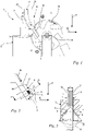
- the 1 shows an embodiment of the device 1 according to the invention for weighing capsules 10 with a filling 11.
- the device 1 is shown in the usual upright operating position relative to a horizontal direction 50 and a weight force direction 51 orthogonal thereto.
- the direction of the weight force 51 corresponds to the direction of gravity or the acceleration of gravity.
- the capsule 10 to be weighed is shown here by way of example as a plug-in capsule with a lower capsule part 13 and an attached upper capsule part 12 .
- the capsule 10 contains a filling 11 with grains indicated graphically ( 2 ), according to which the filling is a powder, granules or the like.
- the filling is a powder, granules or the like.
- liquids can also be provided as filling 11 . In any case, it is primarily about fillings 11 that have flowing or flow-like properties.
- the capsule 10 is only partially filled, that is to say that the filling 11 does not completely fill the interior of the capsule 10 .
- completely filled capsules 10 can also be weighed with the method according to the invention and the device according to the invention.
- the device comprises a weighing unit 2 with a weighing receptacle 3 for each individual capsule 10 to be weighed.
- the device 1 also comprises a feed channel 6 for feeding individual capsules 10 to the respective weighing unit 2.
- the feed channel 6 is designed as a chute . Accordingly, the feed channel 6 has such an inclination relative to the horizontal direction 50 that the capsule 10 through the feed channel 6 to the weighing unit 2 slips through.
- the feed channel 6 extends to the weighing unit 2, as a result of which the capsule 10 can slide from the feed channel 6 directly onto the weighing unit 2.
- the device 1 comprises a stopping device 7 for the capsule 10 brought up to the weighing unit 2 in the direction of movement 52.
- the stopping device 7 is part of the weighing receptacle 3.
- the stopping device 7 is designed to hold the stopped capsule 10 in a receiving section 4 of the weighing receptacle 3 in Movement direction 52 to keep form-fitting.
- a projection is formed on the stop device 7 in relation to the receiving section 4 of the weighing receptacle 3 .
- the capsule 10 slides over the feed channel 6 in the direction of movement 52 onto the weighing receptacle 3 and comes to rest on the projection 19 at its front end 18 in the direction of movement 52 .
- the projection 19 of the stopping device 7 forms a stop for the capsule 10 in the direction of movement 52. Once the capsule 10 has come to rest, its weight in the weighing receptacle 3 can be measured. The projection 19 of the stop device 7 also prevents the capsule 10 from sliding off the weighing receptacle 3 during the weighing process.
- the stopping of the capsule 10 also leads to a braking of the filling 11 within the capsule 10 counter to the direction of movement 52.
- the filling 11 collects in the area of the front end 18 of the capsule 10, while the rear end 17 of the capsule 10 is free is.
- the filling 11 within the capsule 10 after stopping from the area of the front end 18 at least partially flows or trickles back onto the lower wall area of the capsule 10 in the direction of the weight force 51 .
- the movement of the filling 11 within the capsule 10 leads to deviations in the weighing of the capsule 10. This has the consequence that the time span increases until the capsule 10 is in a rest position after stopping and can be weighed with sufficient accuracy.
- the receiving portion 4 is the area of the weighing receptacle 3 within which the capsule 10 is deposited.
- the receiving section 4 extends along its longitudinal axis 5.
- the horizontal direction 50 and the direction of weight force 51 running perpendicular thereto are shown during normal operation, to which reference is made here. It is known from the prior art described at the outset that corresponding receiving sections are aligned essentially horizontally, that is to say parallel to the horizontal direction 50 . Accordingly, the capsule 10 also rests on the receiving section 4 with its longitudinal axis essentially horizontally.
- the horizontal orientation of the capsule when it stops, when it is transferred to the weighing unit and when it lies on the receiving section of the weighing receptacle results in a pronounced rearrangement of the filling within the capsule from the front end back to the lower capsule wall.
- a reliable weighing can only be carried out after a certain stabilization phase of the filling.
- the receiving portion 4 of the weighing receiver 3 is formed such that the stopped capsule 10 is inclined with respect to the horizontal direction 50 .
- the longitudinal axis 5 of the receiving section 4 encloses an angle of inclination ⁇ with the horizontal direction 50 .
- the angle of inclination ⁇ is in a range from 30° to 90°, preferably in a range from 45° to 75° and in particular in a range from 50° to 60°.
- a front end 15 of the receiving section 4 in the direction of movement 52 of the capsule 10 is lower than a rear end 14 of the receiving section 4 in the direction of movement 50.
- the projection 19 of the stop device 7 is formed on the front end 15 of the receiving section 4.
- the capsule 10 lies with its front end 18 on the front end 15 of the receiving section 4 and also contacts the stop device 7. Furthermore, the capsule lies with its rear end 17 on the rear end 14 of the receiving section 4.
- the frictional connection between the capsule 10 and the receiving section 4 of the weighing receptacle 3 is too low at such an angle of inclination ⁇ to be able to hold the capsule 10 without the stop device 7 .
- the capsule 10 would slide off the receiving section 4 in the direction of movement 52 without a stop device 7 .
- the stopping device 7 is provided directly on the weighing unit 2 .
- the stopping device 7 thus has two tasks, namely to stop the capsule 10 when it slips out of the feed channel 6 onto the weighing receptacle 3 and to hold the capsule in a stopped position on the receiving section 4 of the weighing receptacle 3 during the weighing .
- the weighing receptacle 3 and the stop device 7 are firmly connected to one another.
- the weighing unit 2 is designed in one piece with the stop device 7 .
- the device 1 comprises a capsule transporter 16.
- the capsule transporter 16 accepts the capsule 10 after it has been weighed and sorts it out.
- the capsule transporter 16 is designed as a rotatable pocket wheel.
- the capsule transporter 16 has at least one receiving pocket 20 .
- a plurality, in particular five, receiving pockets 20 are provided on the capsule transporter 16 .
- the upper inside of a receiving pocket 20 aligned with the feed channel 6 with respect to the weight force direction forms an upper movement stop for the capsule 10 so that it comes to rest on the receiving section 4 in its longitudinal direction parallel to the direction of movement 50 .
- the capsule transporter continues to rotate in the direction of rotation 22 .
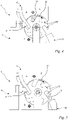
- the capsule 10 is removed from the weighing receptacle 3 and carried on in the receiving pocket 20 of the capsule transporter 16 ( 4 ).
- the device 1 comprises a sorting chute 23 which is arranged on the capsule transporter 16 in such a way that the capsule 10 falls out of the receiving pocket 20 into the sorting chute 23 when the capsule transporter 16 rotates accordingly ( figure 5 ).
- the capsule 10 is represented schematically as a dashed circular line.
- the receiving section 4 is divided into two individual partial surface sections 8, 8'.
- the capsule 10 rests against the two surface sections 8, 8'.
- Viewed in cross section of the receiving section 4, the two partial surface sections 8, 8' are inclined towards one another.
- the surface sections 8, 8' run parallel to the longitudinal axis 5 of the receiving section 4.
- the two surface sections 8, 8' enclose a dihedral angle ⁇ , with the dihedral angle ⁇ being less than 180°.
- the dihedral angle ⁇ is in a range from 60° to 120° and is at least approximately 80° in the preferred exemplary embodiment shown.
- the capsule 10 is automatically held centered between the partial surface sections 8, 8'.
- This configuration of the receiving section 4 also allows capsules 10 of different sizes to be held.
- an opening 9 is provided on the weighing receptacle 3 .
- the opening 9 is designed in such a way that the capsule transporter 16 can move through the opening 9 and thereby pick up the capsule 10 .
- the capsule 10 is lifted from the weighing receptacle 3 .
- the opening 9 is formed between the two partial surface sections 8, 8'.
- the opening 9 is designed as a slot.
- the opening 9 can also have a different contour, which enables the capsule transporter 16 to remove the capsule 10 from the weighing receptacle 3 .
- the device 1 comprises a housing 24, the housing 24 surrounding the weighing receptacle 3.
- the feed channel 6 is formed in the housing 24 .
- the housing 24 surrounds the weighing receptacle 3 in such a way that air flows from outside the housing 24 can only reach the weighing receptacle 3 via the feed channel 6 . As a result, the air currents acting on the weighing receptacle 3 are reduced.
- the capsule transporter 16 is mounted so that it can rotate about its axis of rotation 25 , preferably on the housing 24 . As in 3 shown, the capsule transporter 16 is at least partially arranged in the opening 9 of the weighing receptacle 3 .
- the capsule transporter 16 has a width a, measured in the direction of its axis of rotation 25 , which extends from its first end face 26 to its second end face 27 .
- the width a of the capsule transporter 16 is preferably less than a diameter of the capsule 10.
- the width a of the capsule transporter 16 is at most 75%, preferably 50%, of the diameter d of the capsule 10.
- the opening 9 of the weighing receptacle 3 also has a direction the axis of rotation 25 of the capsule transporter 16 measured width c.
- the width c of the opening 9 is greater than the width a of the capsule transporter 16.
- This narrow design of the capsule transporter 16 means that the air masses moved by the capsule transporter 16 are small, so that the influence on the weighing receptacle 3 is also small.
- the capsule transporter 16 is surrounded at its end faces 26, 27 by the housing 24 in such a way that the capsule 10 is guided in the receiving pockets 20 on the housing 24. As a result, the capsules 10 cannot fall out of the receiving pockets 20 of the capsule transporter 16.
- the receiving section 4 is divided into the two individual partial surface sections 8, 8'.
- the invention is shown here as an example in single-lane operation with only one feed channel 6 and only one weighing unit 2 .
- multi-lane, parallel versions can be expedient without further ado, in which a corresponding number of feed channels 6 and weighing units 2 are arranged next to one another for the simultaneous and parallel testing of several capsules 10 .
Landscapes
- Physics & Mathematics (AREA)
- General Physics & Mathematics (AREA)
- Basic Packing Technique (AREA)
- Medical Preparation Storing Or Oral Administration Devices (AREA)
Abstract
Description
- Die Erfindung betrifft eine Vorrichtung zum Wiegen von Kapseln nach dem Oberbegriff des Anspruchs 1 sowie ein Verfahren zum Wiegen von Kapseln mittels einer solchen Vorrichtung.
- Im pharmazeutischen Bereich und auch im Bereich von Nahrungsergänzungsmitteln werden zahlreiche Präparate in Kapseln abgefüllt, die zur oralen Einnahme vorgesehen sind. Bei verschiedenen Präparaten kommt es darauf an, dass diese als Einheitsdosis in der Kapsel mit einer fest definierten und exakt eingehaltenen Masse bereitgestellt werden. Geeignete Dosiervorrichtungen und -verfahren sollen sicherstellen, dass unter den Bedingungen der Großserienabfüllung sehr enge Massentoleranzen von beispielsweise ± 2 mg eingehalten werden.
- Solche Anforderungen an die Zielmasse gehen zunehmend auch mit dem Wunsch nach geeigneten Prüf- bzw. Verifikationsmaßnahmen einher. Zur Erfüllung solcher Forderungen sind insbesondere mehrspurig aufgebaute Kapselfüllmaschinen und mehrspurige Wiegesysteme im Einsatz. Die befüllten Kapseln werden entweder stichprobenartig auf die richtige Füllmenge kontrolliert oder aber, bei einer entsprechenden Anforderung, einer 100%ige In-Prozess-Kontrolle zugeführt. Dazu werden die Kapseln an eine mehrspurige Kapselwiegemaschine gefördert. Ist keine direkte Verbindung vorhanden, so kann die Kapselwiegemaschine auch von Hand beschickt werden. In der Kapselwiegemaschine werden die einzelnen Kapseln an eine Wiegeeinheit herangeführt. Beim Erreichen der Wiegeeinheit wird die Kapsel aus ihrer Bewegung mittels einer Stoppvorrichtung gestoppt und anschließend auf einer Wiegeaufnahme der Wiegeeinheit horizontal liegend abgelegt. Dort erfolgt dann eine prüfende Wägung der gefüllten Kapsel, bevor sie weitertransportiert und durch die nachfolgende Kapsel an der Wiegevorrichtung ersetzt wird.
- Es hat sich gezeigt, dass die solchermaßen durchgeführte Wägung den limitierenden Faktor hinsichtlich Durchlaufgeschwindigkeit und Ausbringungsmenge darstellt. Für eine im Milligramm-Bereich exakt und wiederholbar durchzuführende Gewichtsmessung muss die jeweilige Kapsel absolut ruhig auf der Wiegeaufnahme aufliegen. Die mit hoher Geschwindigkeit herangeführte Kapsel muss also zunächst abgebremst, also gestoppt und dann sauber abgelegt werden, bevor die eigentliche Wägung durchgeführt werden kann. Für einen schnellen Weitertransport ist dann erneut eine hohe Beschleunigung erforderlich. Um trotzdem eine für die Messung ausreichend lange Ruhephase zu haben, darf die Taktzahl der Maschine insgesamt ein bestimmtes Maß nicht überschreiten. Eine Steigerung der Ausbringungsmenge kann unter diesen Bedingungen nur durch eine Erhöhung der Anzahl der Maschinenspuren erreicht werden, was den für die Wiegevorrichtung ohnehin schon hohen Investitionsaufwand weiter erhöht.
- Der Erfindung liegt die Aufgabe zugrunde, eine gattungsgemäße Vorrichtung zum Wiegen von gefüllten Kapseln derart weiterzubilden, dass eine präzise Wägung auch bei verkürzten Taktzeiten möglich ist.
- Diese Aufgabe wird durch eine Vorrichtung mit den Merkmalen des Anspruchs 1 gelöst.
- Der Erfindung liegt des Weiteren die Aufgabe zugrunde, ein schnelleres Verfahren zum Wiegen von Kapseln anzugeben.
- Diese Aufgabe wird durch ein Verfahren mit den Merkmalen des Anspruchs 11 gelöst.
- Die Erfindung basiert zunächst auf der Kenntnis, dass Kapseln mit unterschiedlichem Füllgrad unterschiedlich empfindlich auf Verkürzungen der Wiegetaktzeiten reagieren. So wurde zunächst erkannt, dass vollgefüllte Kapseln in einer relativ kurzen Zeit exakt gewogen werden können, während teilgefüllte Kapseln hierfür einen im Vergleich längeren Zeitraum benötigen. Dies führte zu der weiteren erfindungsgemäßen Erkenntnis, dass die Füllung von teilgefüllten Kapseln auch dann noch ein dynamisches Verhalten zeigen, wenn der Vorgang des Abbremsens und Ablegen der Kapsel auf der Wiegeaufnahme an sich bereits abgeschlossen ist. Infolge der anfänglich wirkenden Verzögerung beim Stoppen sammelt sich die Füllung am in Bewegungsrichtung vorderen Ende der Kapsel. Nach der Ablage auf der Wiegeaufnahme rieselt die vorne in der Kapsel angesammelte pulver- oder granulatartige Füllung zumindest teilweise auf die in Gewichtskraftrichtung unten liegende Kapselwand zurück, wobei sich nach Art einer Schüttung eine Böschung mit einem bestimmten Böschungswinkel ausbildet. Dieser Vorgang des Zurückrieselns, gegebenenfalls in Verbindung mit einer Böschungsbildung nimmt eine bestimmte Zeit in Anspruch, während die Kapsel bereits auf der Wiegeaufnahme liegt. Solange die Füllung im Kapselinneren noch in Bewegung ist, werden die Messergebnisse einer Wägung verfälscht. Im Ergebnis kann eine schnelle und exakte Wägung der gesamten Kapsel erst dann vorgenommen werden, wenn erstens zusammen mit der Kapselhülle auch die Füllung zur Ruhe gekommen ist, und wenn zweitens für alle Kapseln vergleichbare Ruhelagen erzielt werden können.
- Aufbauend hierauf sieht die Erfindung eine Vorrichtung vor, in der eine Stoppvorrichtung Teil der Wiegeaufnahme ist und dazu ausgelegt ist, die jeweils gestoppte Kapsel in einem Aufnahmeabschnitt der Wiegeaufnahme in Bewegungsrichtung formschlüssig zu halten. Dies ermöglicht den Aufnahmeabschnitt der Wiegeaufnahme bezüglich einer Horizontalrichtung derart geneigt auszubilden, dass ein bezogen auf die Bewegungsrichtung vorderes Ende des Aufnahmeabschnittes tiefer liegt als ein hinteres Ende des Aufnahmeabschnittes. Folglich liegt auch die Kapsel in einer entsprechend geneigten Lage. Während des Wiegens der Kapsel wird diese durch die Stoppvorrichtung formschlüssig gehalten. Diese Ausgestaltung der Stoppvorrichtung erlaubt besonders hohe Neigungswinkel zwischen Aufnahmeabschnitt und Horizontalrichtung, ohne dass die Kapsel von dem Aufnahmeabschnitt rutscht. Aufgrund der erfindungsgemäßen Neigung des Aufnahmeabschnittes der Wiegeaufnahme und der erfindungsgemäß geneigten Ablage der Kapsel hierauf, kann die Zeitspanne deutlich verringert werden, in welcher die Füllung nach dem Stoppen der Kapsel aus der vorderen Stopp-Position zurück rieselt oder fließt. Im Vergleich zum Stand der Technik können deutlich kürzere Wartezeiten eingehalten werden, bevor eine verlässliche Wägung vorgenommen werden kann.
- Es ist vorteilhaft vorgesehen, dass der Aufnahmeabschnitt der Wiegeaufnahme eine Längsachse aufweist, wobei die Längsachse des Aufnahmeabschnittes bezüglich der Horizontalrichtung in einem Neigungswinkel geneigt ist. Bevorzugt liegt der Neigungswinkel in einem Bereich von 30° bis 90°, bevorzugt in einem Bereich von 45° bis 75° und insbesondere in einem Bereich von 50° bis 60°. Je höher der Neigungswinkel ist, desto schneller stellt sich eine Ruhephase des Füllgutes ein. Ist der Neigungswinkel zu hoch gewählt, kann die Kapsel aus der Wiegeaufnahme springen. Demnach ist ein geeigneter Neigungswinkel zu wählen, der eine sichere Endlage der Kapsel in der Wiegeaufnahme sowie eine schnelle Ruhephase der Füllung nach dem Stoppen der Kapsel ermöglicht.
- Vorzugsweise ist der Aufnahmeabschnitt durch zwei Teilflächenabschnitte gebildet, wobei die Teilflächenabschnitte im Querschnitt des Aufnahmeabschnittes betrachtet einander zugewandt geneigt sind. Die Neigung der Teilflächenabschnitte zueinander ermöglicht eine automatische Zentrierung der Kapsel an dem Aufnahmeabschnitt, wodurch Kapseln verschiedener Größe positioniert werden können. Bevorzugt schließen die beiden Teilflächenabschnitte einen Flächenwinkel ein, der in einem Bereich von 120° bis 60° liegt, insbesondere näherungsweise 90° beträgt.
- Es ist vorzugsweise vorgesehen, dass die beiden Teilflächenabschnitte durch eine Öffnung voneinander getrennt sind. Die Öffnung ermöglicht dem Kapseltransporter durch die Wiegeaufnahme hindurchzufahren und dabei die Kapsel aus der Wiegeaufnahme aufzunehmen. Die Öffnung ist insbesondere als ein Schlitz ausgebildet. In einer alternativen Ausgestaltung kann es aber auch zweckmäßig sein, andere Konturen für die Öffnung vorzusehen. Die Öffnungskontur ist selbstverständlich an die des Kapseltransporters anzupassen.
- Vorzugsweise ist der Zuführkanal als ein Fallschacht ausgebildet. Dies hat zur Folge, dass sich die Kapsel entlang des Zuführkanals mit hoher Geschwindigkeit in Richtung zur Wiegeaufnahme bewegt. Um die Kapsel dennoch an der Wiegeaufnahme halten zu können, ist die Stoppvorrichtung als Anschlag der Kapsel in Bewegungsrichtung ausgebildet. Es ist vorzugsweise vorgesehen, dass die Vorrichtung einen Kapseltransporter zum Aussortieren der Kapsel aufweist. Der Kapseltransporter kann insbesondere als drehbares Taschenrad ausgebildet sein. Dies ermöglicht einen konstruktiv einfachen Aufbau der erfindungsgemäßen Vorrichtung.
- Ein Ausführungsbeispiel der Erfindung ist nachfolgend anhand der Zeichnung näher beschrieben. Es zeigen:
- Fig. 1
- in einer schematischen Stirnansicht eine erfindungsgemäße Vorrichtung zum Wiegen von Kapseln beim Halten der Kapsel,
- Fig. 2
- in einer ausschnittsweisen, schematischen Stirnansicht die Vorrichtung nach
Fig. 1 mit an der Stoppvorrichtung gehaltener Kapsel, - Fig. 3
- in einer schematischen Schnittdarstellung entlang der in
Fig. 2 dargestellten Schnittlinie in Richtung der Pfeile III die Wiegeaufnahme, - Fig. 4
- in einer schematischen Stirnansicht die Vorrichtung zum Wiegen von Kapseln nach
Fig. 1 mit im Taschenrad aufgenommener Kapsel und - Fig. 5
- in einer schematischen Stirnansicht die Vorrichtung zum Wiegen von Kapseln nach
Fig. 1 beim Aussortieren der Kapsel. - Die
Fig. 1 zeigt eine Ausführung der erfindungsgemäßen Vorrichtung 1 zum Wiegen von Kapseln 10 mit einer Füllung 11. Die Vorrichtung 1 ist in gewöhnlicher, aufrecht stehender Betriebsposition relativ zu einer Horizontalrichtung 50 und einer orthogonal dazu liegenden Gewichtskraftrichtung 51 gezeigt. Die Gewichtskraftrichtung 51 entspricht der Richtung der Erdanziehungskraft beziehungsweise der Erdbeschleunigung. - Die zu wiegende Kapsel 10 ist hier beispielhaft als Steckkapsel mit einem Kapselunterteil 13 und einem aufgesteckten Kapseloberteil 12 gezeigt. Es können aber auch andere, beispielsweise vollständig geschlossene Kapselformen in Betracht kommen. Die Kapsel 10 enthält eine Füllung 11 mit graphisch angedeuteten Körnern (
Fig. 2 ), demnach die Füllung ein Pulver, ein Granulat oder dergleichen ist. Im Rahmen der Erfindung können aber auch Flüssigkeiten als Füllung 11 vorgesehen sein. Jedenfalls geht es vorrangig um Füllungen 11, die fließende oder fließähnliche Eigenschaften haben. Außerdem wird inFig. 2 noch deutlich, dass die Kapsel 10 nur teilgefüllt ist, demnach also die Füllung 11 den Innenraum der Kapsel 10 nicht vollständig ausfüllt. Mit dem erfindungsgemäßen Verfahren und der erfindungsgemäßen Vorrichtung können allerdings auch vollständig gefüllte Kapseln 10 gewogen werden. - Wie in
Fig. 1 gezeigt, umfasst die Vorrichtung eine Wiegeeinheit 2 mit einer Wiegeaufnahme 3 für jeweils eine einzelne zu wiegende Kapsel 10. Ferner umfasst die Vorrichtung 1 einen Zuführkanal 6 zum Heranführen einzelner Kapseln 10 an die jeweilige Wiegeeinheit 2. Im Ausführungsbeispiel ist der Zuführkanal 6 als ein Fallschacht ausgebildet. Demnach weist der Zuführkanal 6 eine gegenüber der Horizontalrichtung 50 derartige Neigung auf, dass die Kapsel 10 durch den Zuführkanal 6 bis zur Wiegeeinheit 2 hindurchrutscht. Der Zuführkanal 6 erstreckt sich bis zur Wiegeeinheit 2, wodurch die die Kapsel 10 von dem Zuführkanal 6 unmittelbar auf die Wiegeeinheit 2 gleiten kann. - Wie in den
Figuren 1 und 2 gezeigt, umfasst die Vorrichtung 1 eine Stoppvorrichtung 7 für die in Bewegungsrichtung 52 an die Wiegeeinheit 2 herangeführte Kapsel 10. Die Stoppvorrichtung 7 ist Teil der Wiegeaufnahme 3. Die Stoppvorrichtung 7 ist dazu ausgelegt, die gestoppte Kapsel 10 in einem Aufnahmeabschnitt 4 der Wiegeaufnahme 3 in Bewegungsrichtung 52 formschlüssig zu halten. Hierzu ist an der Stoppvorrichtung 7 ein Vorsprung gegenüber dem Aufnahmeabschnitt 4 der Wiegeaufnahme 3 ausgebildet. Die Kapsel 10 gleitet über den Zuführkanal 6 in Bewegungsrichtung 52 auf die Wiegeaufnahme 3 und kommt an ihrem in Bewegungsrichtung 52 vorderen Ende 18 am Vorsprung 19 zum Liegen. Demnach bildet der Vorsprung 19 der Stoppvorrichtung 7 einen Anschlag für die Kapsel 10 in Bewegungsrichtung 52. Ist die Kapsel 10 zum Liegen gekommen, kann deren Gewicht in der Wiegeaufnahme 3 gemessen werden. Der Vorsprung 19 der Stoppvorrichtung 7 verhindert zudem, dass die Kapsel 10 während des Wiegevorganges von der Wiegeaufnahme 3 abgleitet. - Das Stoppen der Kapsel 10 führt entgegen der Bewegungsrichtung 52 auch zu einem Bremsen der Füllung 11 innerhalb der Kapsel 10. Infolge der wirkenden Massenkräfte sammelt sich die Füllung 11 im Bereich des vorderen Endes 18 der Kapsel 10, während das hintere Ende 17 der Kapsel 10 frei ist. Bei in etwa horizontal positionierten Kapseln 10 konnte beobachtet werden, dass die Füllung 11 innerhalb der Kapsel 10 nach dem Stoppen aus dem Bereich des vorderen Endes 18 zumindest teilweise zurück auf den in Gewichtskraftrichtung 51 unteren Wandbereich der Kapsel 10 fließt bzw. rieselt. Die Bewegung der Füllung 11 innerhalb der Kapsel 10 führt zu Abweichungen der Wägung der Kapsel 10. Dies hat zur Folge, dass sich die Zeitspanne erhöht, bis sich die Kapsel 10 nach dem Stoppen in einer Ruhelage befindet und mit ausreichender Genauigkeit gewogen werden kann.
- Wie in
Fig. 2 gezeigt, ist der Aufnahmeabschnitt 4 der Bereich der Wiegeaufnahme 3, innerhalb dessen die Kapsel 10 abgelegt wird. Der Aufnahmeabschnitt 4 erstreckt sich dabei entlang seiner Längsachse 5. Als Referenz für die Orientierung des Aufnahmeabschnitts 4 und der Kapsel 10 sind die Horizontalrichtung 50 und die senkrecht dazu verlaufende Gewichtskraftrichtung 51 beim gewöhnlichen Betrieb eingezeichnet, auf die hier Bezug genommen wird. Aus dem anfänglich beschriebenen Stand der Technik ist bekannt, dass entsprechende Aufnahmeabschnitte im Wesentlichen horizontal, also parallel zur Horizontalrichtung 50 ausgerichtet. Dementsprechend liegt auch die Kapsel 10 mit ihrer Längsachse im Wesentlichen horizontal auf dem Aufnahmeabschnitt 4 auf. Gemäß Stand der Technik folgt aus der horizontalen Ausrichtung der Kapsel beim Stoppen, bei der Übergabe zur Wiegeeinheit und beim Aufliegen auf dem Aufnahmeabschnitt der Wiegeaufnahme eine ausgeprägte Umlagerung der Füllung innerhalb der Kapsel vom vorderen Ende zurück zur unteren Kapselwand. Infolge kann eine zuverlässige Wägung erst nach einer bestimmten Beruhigungsphase der Füllung vorgenommen werden. - Wie in den
Figuren 1 und 2 gezeigt, ist der Aufnahmeabschnitt 4 der Wiegeaufnahme 3 derart ausgebildet, dass die gestoppte Kapsel 10 gegenüber der Horizontalrichtung 50 geneigt angeordnet ist. Die Längsachse 5 des Aufnahmeabschnittes 4 schließt mit der Horizontalrichtung 50 einen Neigungswinkel α ein. Wie inFig. 2 gezeigt, liegt der Neigungswinkel α in einem Bereich von 30° bis 90°, bevorzugt in einem Bereich von 45° bis 75° und insbesondere in einem Bereich von 50° bis 60°. Dies hat zur Folge, dass ein in Bewegungsrichtung 52 der Kapsel 10 vorderes Ende 15 des Aufnahmeabschnittes 4 tiefer liegt als ein in Bewegungsrichtung 50 hinteres Ende 14 des Aufnahmeabschnittes 4. An dem vorderen Ende 15 des Aufnahmeabschnittes 4 ist der Vorsprung 19 der Stoppvorrichtung 7 ausgebildet. Wie inFig. 2 gezeigt, liegt die Kapsel 10 mit ihrem vorderen Ende 18 auf dem vorderen Ende 15 des Aufnahmeabschnitts 4 und kontaktiert zudem die Stoppvorrichtung 7. Ferner liegt die Kapsel mit ihrem hinteren Ende 17 auf dem hinteren Ende 14 des Aufnahmeabschnittes 4. Je größer der Neigungswinkel α zwischen der Längsachse 5 und der Horizontalrichtung 50 ist, desto geringer ist die Umlagerung der Füllung 11 der Kapsel 10, nachdem die Kapsel 10 gestoppt wurde. Demnach reduziert sich auch die Dauer der Beruhigungsphase der Füllung 11. Aus diesem Grund ist der Neigungswinkel α erfindungsgemäß möglichst hoch gewählt. Dies hat zur Folge, dass die Kapsel 10 an dem Aufnahmeabschnitt 4 der Wiegeaufnahme 3 während der Wägung mittels der Stoppvorrichtung 7 gehalten werden muss. Der Reibkraftschluss zwischen der Kapsel 10 und dem Aufnahmeabschnitt 4 der Wiegeaufnahme 3 ist bei einem derartigen Neigungswinkel α zu gering, um die Kapsel 10 ohne die Stoppvorrichtung 7 halten zu können. Die Kapsel 10 würde ohne Stoppvorrichtung 7 in Bewegungsrichtung 52 von dem Aufnahmeabschnitt 4 abgleiten. Die Stoppvorrichtung 7 ist unmittelbar an der Wiegeeinheit 2 vorgesehen. Der Stoppvorrichtung 7 werden somit zwei Aufgaben zu teil, nämlich zum einen die Kapsel 10 zu stoppen, wenn diese aus dem Zuführkanal 6 auf die Wiegeaufnahme 3 rutscht, und zum anderen die Kapsel in gestoppter Stellung auf dem Aufnahmeabschnitt 4 der Wiegeaufnahme 3während der Wägung zu halten. Die Wiegeaufnahme 3 und die Stoppvorrichtung 7 sind fest miteinander verbunden. In der bevorzugten Ausführung ist die Wiegeeinheit 2 mit der Stoppvorrichtung 7 einteilig ausgebildet. - Wie in
Fig. 1 gezeigt, umfasst die Vorrichtung 1 einen Kapseltransporter 16. Der Kapseltransporter 16 nimmt die Kapsel 10 nach der Wägung auf und sortiert diese aus. Im bevorzugten Ausführungsbeispiel ist der Kapseltransporter 16 als drehbares Taschenrad ausgebildet. Der Kapseltransporter 16 weist mindestens eine Aufnahmetasche 20 auf. Im bevorzugten Ausführungsbeispiel sind an dem Kapseltransporter 16 mehrere, insbesondere fünf Aufnahmetaschen 20 vorgesehen. Beim Zuführen der Kapsel 10 befindet sich der Kapseltransporter in einer Offenstellung 21, in der die Aufnahmetasche 20 fluchtend zum Zuführkanal 6 ausgerichtet ist. Demnach kann die Kapsel 10 in die Wiegeaufnahme 3 gleiten. Die bezüglich der Gewichtskraftrichtung obere Innenseite einer zum Zuführkanal 6 fluchtende Aufnahmetasche 20 bildet einen oberen Bewegungsanschlag für die Kapsel 10, so dass diese in ihrer Längsrichtung parallel zur Bewegungsrichtung 50 auf dem Aufnahmeabschnitt 4 zum Liegen kommt. Nach der Wägung dreht sich der Kapseltransporter in Drehrichtung 22 weiter. Dabei wird die Kapsel 10 von der Wiegeaufnahme 3 entnommen und in der Aufnahmetasche 20 des Kapseltransporters 16 weitergeführt (Fig. 4 ). Ferner umfasst die Vorrichtung 1 einen Aussortierschacht 23, der derart an dem Kapseltransporter 16 angeordnet ist, dass die Kapsel 10 bei entsprechender Drehung des Kapseltransporters 16 aus der Aufnahmetasche 20 in den Aussortierschacht 23 fällt (Fig. 5 ). -
Fig. 3 zeigt eine schematische Schnittdarstellung der Wiegeaufnahme 3. Die Kapsel 10 ist schematisch als eine gestrichelte Kreislinie dargestellt. Wie inFig. 3 gezeigt, unterteilt sich der Aufnahmeabschnitt 4 in zwei einzelne Teilflächenabschnitte 8, 8'. Die Kapsel 10 liegt an den beiden Teilflächenabschnitten 8, 8' an. Die beiden Teilflächenabschnitte 8, 8' sind im Querschnitt des Aufnahmeabschnittes 4 betrachtet einander zugewandt geneigt. Die Teilflächenabschnitte 8, 8' verlaufen parallel zur Längsachse 5 des Aufnahmeabschnittes 4. Die beiden Teilflächenabschnitte 8, 8' schließen einen Flächenwinkel β ein, wobei der Flächenwinkel β kleiner 180° ist. In bevorzugter Ausführung liegt der Flächenwinkel β in einem Bereich von 60° bis 120° und beträgt im gezeigten bevorzugten Ausführungsbeispiel zumindest näherungsweise 80°. Hierdurch wird die Kapsel 10 automatisch zentriert zwischen den Teilflächenabschnitten 8, 8' gehalten. Durch diese Ausgestaltung des Aufnahmeabschnittes 4 können auch Kapseln 10 verschiedener Größe gehalten werden. Ferner ist an der Wiegeaufnahme 3 eine Öffnung 9 vorgesehen. Die Öffnung 9 ist derart ausgebildet, dass der Kapseltransporter 16 durch die Öffnung 9 fahren und dabei die Kapsel 10 aufnehmen kann. Die Kapsel 10 wird von der Wiegeaufnahme 3 angehoben. Wie inFig. 3 gezeigt, ist die Öffnung 9 zwischen den beiden Teilflächenabschnitten 8, 8' ausgebildet. Im bevorzugten Ausführungsbeispiel ist die Öffnung 9 als Schlitz ausgebildet. Die Öffnung 9 kann auch eine andere Kontur aufweisen, die es dem Kapseltransporter 16 ermöglicht, die Kapsel 10 aus der Wiegeaufnahme 3 zu entnehmen. - Derartige Wiegeeinheiten 2 sind äußerst sensitive Messsysteme, die bereits bei geringer Krafteinwirkung reagieren. So können die Messergebnisse beim Wiegen einer Kapsel 10 bereits durch ungewünschte Luftströmungen, die auf die Wiegeaufnahme 3 oder auf die Kapsel 10 wirken, verfälscht werden. Daher sieht das in
Fig. 1 gezeigte Ausführungsbeispiel mehrere Maßnahmen zur Reduzierung von Luftströmungen an der Wiegeeinheit 2 vor. Wie inFig. 1 gezeigt, umfasst die Vorrichtung 1 ein Gehäuse 24, wobei das Gehäuse 24 die Wiegeaufnahme 3 umgibt. Der Zuführkanal 6 ist im Gehäuse 24 ausgebildet. Das Gehäuse 24 umgibt die Wiegeaufnahme 3 derart, dass Luftströmungen von außerhalb des Gehäuses 24 lediglich über den Zuführkanal 6 an die Wiegeaufnahme 3 gelangen können. Dadurch sind die auf die Wiegeaufnahme 3 wirkenden Luftströmungen reduziert. - Um auch die vom Kapseltransporter 16 ausgehenden Luftströmungen zu reduzieren, weißt dieser eine äußerst schmale Bauweise auf. Der Kapseltransporter 16 ist um seine Drehachse 25 drehend, vorzugsweise am Gehäuse 24, gelagert. Wie in
Fig. 3 gezeigt, ist der Kapseltransporter 16 zumindest teilweise in der Öffnung 9 der Wiegeaufnahme 3 angeordnet. Der Kapseltransporter 16 weist eine in Richtung seiner Drehachse 25 gemessene Breite a auf, die sich von seiner ersten Stirnseite 26 bis zu seiner zweiten Stirnseite 27 erstreckt. Die Breite a des Kapseltransporters 16 ist vorzugsweise geringer als ein Durchmesser der Kapsel 10. Ferner beträgt die Breite a des Kapseltransporters 16 höchstens 75%, vorzugsweise 50% des Durchmessers d der Kapsel 10. Ferner weist die Öffnung 9 der Wiegeaufnahme 3 eine ebenfalls in Richtung der Drehachse 25 des Kapseltransporters 16 gemessene Breite c auf. Die Breite c der Öffnung 9 ist größer als die Breite a des Kapseltransporters 16. Diese schmale Ausbildung des Kapseltransporters 16 führt dazu, dass die vom Kapseltransporter 16 bewegten Luftmassen gering sind, wodurch der Einfluss auf die Wiegeaufnahme 3 ebenfalls gering ist. Ferner ist der Kapseltransporter 16 an seinen Stirnseiten 26, 27 von dem Gehäuse 24 derart umgeben, dass die Kapsel 10 gehalten in den Aufnahmetaschen 20 am Gehäuse 24 geführt ist. Dadurch können die Kapseln 10 nicht aus den Aufnahmetaschen 20 des Kapseltransporters 16 fallen. Wie bereits oben ausgeführt, ist der Aufnahmeabschnitt 4 in die zwei einzelnen Teilflächenabschnitte 8, 8' unterteilt. Neben dem Vorteil, Kapseln 10 besser aufnehmen zu können, besteht eine weitere Funktion der Zweiteilung auch darin, dass sich die potentielle Anströmfläche für Luftströmungen an der Wiegeaufnahme 3 reduzieren. Somit kann eine Vielzahl an potentiellen Messstörungen an der Wiegeeinheit vermieden werden. - Die Erfindung ist hier beispielhaft im einspurigen Betrieb mit nur einem Zuführkanal 6 und nur einer Wiegeeinheit 2 dargestellt. Im praktischen Betrieb können aber ohne Weiteres mehrspurige, parallel laufende Ausführungen zweckmäßig sein, bei denen eine entsprechende Anzahl von Zuführkanälen 6 und Wiegeeinheiten 2 für die gleichzeitige und parallel Prüfung von mehreren Kapseln 10 nebeneinander angeordnet sind.
Claims (11)
- Vorrichtung zum Wiegen von Kapseln mit einer Füllung,
wobei die Vorrichtung (1) eine Wiegeeinheit (2) mit einer Wiegeaufnahme (3) für die Kapsel (10), einen Zuführkanal (6) zum Heranführen einzelner Kapseln (10) an die Wiegeeinheit (2) in einer Bewegungsrichtung (52) sowie eine Stoppvorrichtung (7) für die in Bewegungsrichtung (52) herangeführte Kapsel (10) aufweist,
dadurch gekennzeichnet, dass die Stoppvorrichtung (7) Teil der Wiegeaufnahme (3) ist und dazu ausgelegt ist, die jeweils gestoppte Kapsel (10) in einem Aufnahmeabschnitt (4) der Wiegeaufnahme (3) in Bewegungsrichtung (52) formschlüssig zu halten, und
dass der Aufnahmeabschnitt (4) der Wiegeaufnahme (3) bezüglich einer Horizontalrichtung (50) derart geneigt ist, dass ein bezogen auf die Bewegungsrichtung (52) vorderes Ende (15) des Aufnahmeabschnittes (4) tiefer liegt als ein hinteres Ende (14) des Aufnahmeabschnittes (4). - Vorrichtung nach Anspruch 1,
dadurch gekennzeichnet, dass der Aufnahmeabschnitt (4) der Wiegeaufnahme (3) eine Längsachse (5) aufweist, wobei die Längsachse (5) des Aufnahmeabschnittes (4) bezüglich der Horizontalrichtung (50) in einem Neigungswinkel (a) geneigt ist, wobei der Neigungswinkel (a) in einem Bereich von 30° bis 90°, bevorzugt in einem Bereich von 45° bis 75° und insbesondere in einem Bereich von 50° bis 60° liegt. - Vorrichtung nach Anspruch 1 oder 2,
dadurch gekennzeichnet, dass der Aufnahmeabschnitt (4) durch zwei Teilflächenabschnitte (8, 8') gebildet ist, wobei die Teilflächenabschnitte (8, 8') im Querschnitt des Aufnahmeabschnittes (4) betrachtet einander zugewandt geneigt sind. - Vorrichtung nach Anspruch 3,
dadurch gekennzeichnet, dass die beiden Teilflächenabschnitte (8, 8') einen Flächenwinkel (β) einschließen, der in einem Bereich von 120° bis 60° liegt, insbesondere näherungsweise 80° beträgt. - Vorrichtung nach Anspruch 3 oder 4,
dadurch gekennzeichnet, dass die beiden Teilflächenabschnitte (8, 8') durch eine Öffnung (9) voneinander getrennt sind. - Vorrichtung nach Anspruch 5,
dadurch gekennzeichnet, dass die Öffnung (9) als ein Schlitz ausgebildet ist. - Vorrichtung nach einem der Ansprüche 1 bis 6,
dadurch gekennzeichnet, dass der Zuführkanal (6) als ein Fallschacht ausgebildet ist. - Vorrichtung nach einem der Ansprüche 1 bis 7,
dadurch gekennzeichnet, dass die Stoppvorrichtung (7) als Anschlag für die Kapsel (10) in Bewegungsrichtung (52) ausgebildet ist. - Vorrichtung nach einem der Ansprüche 1 bis 8,
dadurch gekennzeichnet, dass die Vorrichtung (1) einen Kapseltransporter (16) zum Aussortieren der Kapsel (10) aufweist. - Vorrichtung nach Anspruch 9,
dadurch gekennzeichnet, dass der Kapseltransporter (16) als drehbares Taschenrad ausgebildet ist. - Verfahren zum Wiegen von Kapseln mit einer Füllung mittels einer Vorrichtung (1) nach einem der Ansprüche 1 bis 10,
umfassend folgende Schritte:- Eine zumindest teilweise mit der Füllung (11) gefüllte Kapsel (10) wird mittels eines Zuführkanals (6) in einer Bewegungsrichtung (52) an die Wiegeeinheit (2) herangeführt;- Beim Erreichen der Wiegeeinheit (2) wird die Kapsel (10) aus ihrer Bewegung in der Bewegungsrichtung (52) mittels einer Stoppvorrichtung (7) gestoppt;- Die gestoppte Kapsel (10) wird in einem Aufnahmeabschnitt (4) der Wiegeaufnahme (3) durch die Stoppvorrichtung (7) in Bewegungsrichtung (52) formschlüssig derart geneigt gehalten, dass ein bezogen auf die Bewegungsrichtung (52) vorderes Ende der Kapsel (18) tiefer liegt als ein hinteres Ende der Kapsel (17);- die geneigt gehaltene Kapsel (10) wird gewogen.
Priority Applications (4)
| Application Number | Priority Date | Filing Date | Title |
|---|---|---|---|
| EP21182828.0A EP4113073B1 (de) | 2021-06-30 | 2021-06-30 | Vorrichtung und verfahren zum wiegen von gefüllten kapseln |
| CA3166584A CA3166584A1 (en) | 2021-06-30 | 2022-06-28 | Device and method for weighing filled capsules |
| US17/854,238 US12123761B2 (en) | 2021-06-30 | 2022-06-30 | Device and method for weighing filled capsules |
| CN202210755509.1A CN115540981A (zh) | 2021-06-30 | 2022-06-30 | 用于称量填充的胶囊的装置和方法 |
Applications Claiming Priority (1)
| Application Number | Priority Date | Filing Date | Title |
|---|---|---|---|
| EP21182828.0A EP4113073B1 (de) | 2021-06-30 | 2021-06-30 | Vorrichtung und verfahren zum wiegen von gefüllten kapseln |
Publications (2)
| Publication Number | Publication Date |
|---|---|
| EP4113073A1 true EP4113073A1 (de) | 2023-01-04 |
| EP4113073B1 EP4113073B1 (de) | 2024-07-31 |
Family
ID=76730394
Family Applications (1)
| Application Number | Title | Priority Date | Filing Date |
|---|---|---|---|
| EP21182828.0A Active EP4113073B1 (de) | 2021-06-30 | 2021-06-30 | Vorrichtung und verfahren zum wiegen von gefüllten kapseln |
Country Status (4)
| Country | Link |
|---|---|
| US (1) | US12123761B2 (de) |
| EP (1) | EP4113073B1 (de) |
| CN (1) | CN115540981A (de) |
| CA (1) | CA3166584A1 (de) |
Families Citing this family (2)
| Publication number | Priority date | Publication date | Assignee | Title |
|---|---|---|---|---|
| DE112024001124T5 (de) * | 2023-03-03 | 2025-12-18 | Setaq Instruments (Shandong) Co., Ltd. | Kapselausgabevorrichtung mit Verlagerungszähnen |
| CN118579498B (zh) * | 2023-03-03 | 2026-06-23 | 山东西泰克仪器有限公司 | 胶囊拨齿发料装置 |
Citations (1)
| Publication number | Priority date | Publication date | Assignee | Title |
|---|---|---|---|---|
| US10935415B2 (en) * | 2017-11-24 | 2021-03-02 | Harro Hoefliger Verpackungsmaschinen Gmbh | Capsule weighing device and capsule filling device having such a capsule weighing device |
Family Cites Families (2)
| Publication number | Priority date | Publication date | Assignee | Title |
|---|---|---|---|---|
| ES2745248T3 (es) * | 2016-12-23 | 2020-02-28 | Hoefliger Harro Verpackung | Dispositivo y método para pesar cápsulas rellenas |
| CN113320949B (zh) * | 2021-06-30 | 2026-07-17 | 上海群町智能科技有限公司 | 一种用于小件制品的连续式称重系统及其称重方法 |
-
2021
- 2021-06-30 EP EP21182828.0A patent/EP4113073B1/de active Active
-
2022
- 2022-06-28 CA CA3166584A patent/CA3166584A1/en active Pending
- 2022-06-30 CN CN202210755509.1A patent/CN115540981A/zh active Pending
- 2022-06-30 US US17/854,238 patent/US12123761B2/en active Active
Patent Citations (1)
| Publication number | Priority date | Publication date | Assignee | Title |
|---|---|---|---|---|
| US10935415B2 (en) * | 2017-11-24 | 2021-03-02 | Harro Hoefliger Verpackungsmaschinen Gmbh | Capsule weighing device and capsule filling device having such a capsule weighing device |
Also Published As
| Publication number | Publication date |
|---|---|
| CN115540981A (zh) | 2022-12-30 |
| US20230020087A1 (en) | 2023-01-19 |
| US12123761B2 (en) | 2024-10-22 |
| EP4113073B1 (de) | 2024-07-31 |
| CA3166584A1 (en) | 2022-12-30 |
Similar Documents
| Publication | Publication Date | Title |
|---|---|---|
| DE2921462C2 (de) | Vorrichtung zum Füllen von Brennstoffstäben | |
| DE69720886T2 (de) | Gewichtsmessgerät von Kapseln | |
| EP3339818B1 (de) | Vorrichtung und verfahren zum wiegen von gefüllten kapseln | |
| DE4325569A1 (de) | Verfahren und Maschine zum Dosieren eines pharmazeutischen Produkts in Kapseln | |
| EP0849572B1 (de) | Verfahren und Vorrichtung zur Kontolle der Tablettenparameter | |
| DE3152509C2 (de) | Vorrichtung zur Erzielung eines bstimmten Endgewichts einer aus mehreren Gegenst{nden bestehenden Menge | |
| EP4113073B1 (de) | Vorrichtung und verfahren zum wiegen von gefüllten kapseln | |
| EP1694590A1 (de) | Vorrichtung zum vereinzeln von gegenständen | |
| DE102009043445A1 (de) | Vorrichtung zur Dosierung pulverförmiger oder körniger Materialien in Kapseln oder dergleichen | |
| EP0685714B1 (de) | Vorrichtung zum Wiegen von Hartgelatinekapseln | |
| EP0099980B1 (de) | Vorrichtung zur Bildung von Tabak-Portionen | |
| DE2834326A1 (de) | Vorrichtung zum pruefen der fuellmenge von kapseln | |
| DE102011117556A1 (de) | Verfahren und gerät zum befüllen von kapseln oder ähnlichem mit mindestens zwei produkten, insbesondere pharmazeutischen produkten in form von kügelchen | |
| EP3488841B1 (de) | Kapselwiegeeinrichtung und kapselfülleinrichtung mit einer solchen kapselwiegeeinrichtung | |
| DE102007019895A1 (de) | Handler zum Testen von gepackten Chips | |
| DE1548210A1 (de) | Maschine zur Pruefung von Glasbehaeltern od.dgl. | |
| DE3925073A1 (de) | Vorrichtung zur pruefung von zigaretten | |
| WO2008040676A1 (de) | Vorrichtung zum orientieren eines behältnisses | |
| DE69004222T2 (de) | Automatische Nietmaschine. | |
| DE3123543C2 (de) | Vorrichtung zur Prüfung und Sortierung von Halbleiterbauteilen | |
| DE69816223T2 (de) | Wägeverfahren für abgebrochenes Stückchen oder Pulver | |
| DE4033644C1 (en) | Cigarette group forming machine - incorporates accumulator with outlet guide system | |
| DE3531119C2 (de) | Einrichtung zum Prüfen und Sortieren von elektronischen Bauelementen, insbesondere integrierten Chips | |
| EP4201390B1 (de) | Kapselfüllmaschine zur befüllung zweiteiliger kapseln und verfahren zur befüllung zweiteiliger kapseln | |
| DE3820341C1 (en) | Method and apparatus for filling receiving containers, in particular sacks, with pourable material in a specified quantity |
Legal Events
| Date | Code | Title | Description |
|---|---|---|---|
| PUAI | Public reference made under article 153(3) epc to a published international application that has entered the european phase |
Free format text: ORIGINAL CODE: 0009012 |
|
| STAA | Information on the status of an ep patent application or granted ep patent |
Free format text: STATUS: THE APPLICATION HAS BEEN PUBLISHED |
|
| AK | Designated contracting states |
Kind code of ref document: A1 Designated state(s): AL AT BE BG CH CY CZ DE DK EE ES FI FR GB GR HR HU IE IS IT LI LT LU LV MC MK MT NL NO PL PT RO RS SE SI SK SM TR |
|
| STAA | Information on the status of an ep patent application or granted ep patent |
Free format text: STATUS: REQUEST FOR EXAMINATION WAS MADE |
|
| 17P | Request for examination filed |
Effective date: 20230703 |
|
| RBV | Designated contracting states (corrected) |
Designated state(s): AL AT BE BG CH CY CZ DE DK EE ES FI FR GB GR HR HU IE IS IT LI LT LU LV MC MK MT NL NO PL PT RO RS SE SI SK SM TR |
|
| GRAP | Despatch of communication of intention to grant a patent |
Free format text: ORIGINAL CODE: EPIDOSNIGR1 |
|
| STAA | Information on the status of an ep patent application or granted ep patent |
Free format text: STATUS: GRANT OF PATENT IS INTENDED |
|
| RIC1 | Information provided on ipc code assigned before grant |
Ipc: G01G 21/22 20060101ALI20240125BHEP Ipc: G01G 17/00 20060101ALI20240125BHEP Ipc: G01G 15/00 20060101AFI20240125BHEP |
|
| INTG | Intention to grant announced |
Effective date: 20240216 |
|
| GRAS | Grant fee paid |
Free format text: ORIGINAL CODE: EPIDOSNIGR3 |
|
| GRAA | (expected) grant |
Free format text: ORIGINAL CODE: 0009210 |
|
| STAA | Information on the status of an ep patent application or granted ep patent |
Free format text: STATUS: THE PATENT HAS BEEN GRANTED |
|
| AK | Designated contracting states |
Kind code of ref document: B1 Designated state(s): AL AT BE BG CH CY CZ DE DK EE ES FI FR GB GR HR HU IE IS IT LI LT LU LV MC MK MT NL NO PL PT RO RS SE SI SK SM TR |
|
| REG | Reference to a national code |
Ref country code: CH Ref legal event code: EP Ref country code: GB Ref legal event code: FG4D Free format text: NOT ENGLISH |
|
| REG | Reference to a national code |
Ref country code: DE Ref legal event code: R096 Ref document number: 502021004558 Country of ref document: DE |
|
| REG | Reference to a national code |
Ref country code: IE Ref legal event code: FG4D Free format text: LANGUAGE OF EP DOCUMENT: GERMAN |
|
| REG | Reference to a national code |
Ref country code: LT Ref legal event code: MG9D |
|
| REG | Reference to a national code |
Ref country code: NL Ref legal event code: MP Effective date: 20240731 |
|
| PG25 | Lapsed in a contracting state [announced via postgrant information from national office to epo] |
Ref country code: PT Free format text: LAPSE BECAUSE OF FAILURE TO SUBMIT A TRANSLATION OF THE DESCRIPTION OR TO PAY THE FEE WITHIN THE PRESCRIBED TIME-LIMIT Effective date: 20241202 |
|
| PG25 | Lapsed in a contracting state [announced via postgrant information from national office to epo] |
Ref country code: PT Free format text: LAPSE BECAUSE OF FAILURE TO SUBMIT A TRANSLATION OF THE DESCRIPTION OR TO PAY THE FEE WITHIN THE PRESCRIBED TIME-LIMIT Effective date: 20241202 |
|
| PG25 | Lapsed in a contracting state [announced via postgrant information from national office to epo] |
Ref country code: NO Free format text: LAPSE BECAUSE OF FAILURE TO SUBMIT A TRANSLATION OF THE DESCRIPTION OR TO PAY THE FEE WITHIN THE PRESCRIBED TIME-LIMIT Effective date: 20241031 |
|
| PG25 | Lapsed in a contracting state [announced via postgrant information from national office to epo] |
Ref country code: GR Free format text: LAPSE BECAUSE OF FAILURE TO SUBMIT A TRANSLATION OF THE DESCRIPTION OR TO PAY THE FEE WITHIN THE PRESCRIBED TIME-LIMIT Effective date: 20241101 Ref country code: NL Free format text: LAPSE BECAUSE OF FAILURE TO SUBMIT A TRANSLATION OF THE DESCRIPTION OR TO PAY THE FEE WITHIN THE PRESCRIBED TIME-LIMIT Effective date: 20240731 Ref country code: FI Free format text: LAPSE BECAUSE OF FAILURE TO SUBMIT A TRANSLATION OF THE DESCRIPTION OR TO PAY THE FEE WITHIN THE PRESCRIBED TIME-LIMIT Effective date: 20240731 Ref country code: PL Free format text: LAPSE BECAUSE OF FAILURE TO SUBMIT A TRANSLATION OF THE DESCRIPTION OR TO PAY THE FEE WITHIN THE PRESCRIBED TIME-LIMIT Effective date: 20240731 |
|
| PG25 | Lapsed in a contracting state [announced via postgrant information from national office to epo] |
Ref country code: BG Free format text: LAPSE BECAUSE OF FAILURE TO SUBMIT A TRANSLATION OF THE DESCRIPTION OR TO PAY THE FEE WITHIN THE PRESCRIBED TIME-LIMIT Effective date: 20240731 |
|
| PG25 | Lapsed in a contracting state [announced via postgrant information from national office to epo] |
Ref country code: LV Free format text: LAPSE BECAUSE OF FAILURE TO SUBMIT A TRANSLATION OF THE DESCRIPTION OR TO PAY THE FEE WITHIN THE PRESCRIBED TIME-LIMIT Effective date: 20240731 |
|
| PG25 | Lapsed in a contracting state [announced via postgrant information from national office to epo] |
Ref country code: IS Free format text: LAPSE BECAUSE OF FAILURE TO SUBMIT A TRANSLATION OF THE DESCRIPTION OR TO PAY THE FEE WITHIN THE PRESCRIBED TIME-LIMIT Effective date: 20241130 |
|
| PG25 | Lapsed in a contracting state [announced via postgrant information from national office to epo] |
Ref country code: HR Free format text: LAPSE BECAUSE OF FAILURE TO SUBMIT A TRANSLATION OF THE DESCRIPTION OR TO PAY THE FEE WITHIN THE PRESCRIBED TIME-LIMIT Effective date: 20240731 |
|
| PG25 | Lapsed in a contracting state [announced via postgrant information from national office to epo] |
Ref country code: RS Free format text: LAPSE BECAUSE OF FAILURE TO SUBMIT A TRANSLATION OF THE DESCRIPTION OR TO PAY THE FEE WITHIN THE PRESCRIBED TIME-LIMIT Effective date: 20241031 Ref country code: ES Free format text: LAPSE BECAUSE OF FAILURE TO SUBMIT A TRANSLATION OF THE DESCRIPTION OR TO PAY THE FEE WITHIN THE PRESCRIBED TIME-LIMIT Effective date: 20240731 |
|
| PG25 | Lapsed in a contracting state [announced via postgrant information from national office to epo] |
Ref country code: RS Free format text: LAPSE BECAUSE OF FAILURE TO SUBMIT A TRANSLATION OF THE DESCRIPTION OR TO PAY THE FEE WITHIN THE PRESCRIBED TIME-LIMIT Effective date: 20241031 Ref country code: PL Free format text: LAPSE BECAUSE OF FAILURE TO SUBMIT A TRANSLATION OF THE DESCRIPTION OR TO PAY THE FEE WITHIN THE PRESCRIBED TIME-LIMIT Effective date: 20240731 Ref country code: NO Free format text: LAPSE BECAUSE OF FAILURE TO SUBMIT A TRANSLATION OF THE DESCRIPTION OR TO PAY THE FEE WITHIN THE PRESCRIBED TIME-LIMIT Effective date: 20241031 Ref country code: NL Free format text: LAPSE BECAUSE OF FAILURE TO SUBMIT A TRANSLATION OF THE DESCRIPTION OR TO PAY THE FEE WITHIN THE PRESCRIBED TIME-LIMIT Effective date: 20240731 Ref country code: LV Free format text: LAPSE BECAUSE OF FAILURE TO SUBMIT A TRANSLATION OF THE DESCRIPTION OR TO PAY THE FEE WITHIN THE PRESCRIBED TIME-LIMIT Effective date: 20240731 Ref country code: IS Free format text: LAPSE BECAUSE OF FAILURE TO SUBMIT A TRANSLATION OF THE DESCRIPTION OR TO PAY THE FEE WITHIN THE PRESCRIBED TIME-LIMIT Effective date: 20241130 Ref country code: HR Free format text: LAPSE BECAUSE OF FAILURE TO SUBMIT A TRANSLATION OF THE DESCRIPTION OR TO PAY THE FEE WITHIN THE PRESCRIBED TIME-LIMIT Effective date: 20240731 Ref country code: GR Free format text: LAPSE BECAUSE OF FAILURE TO SUBMIT A TRANSLATION OF THE DESCRIPTION OR TO PAY THE FEE WITHIN THE PRESCRIBED TIME-LIMIT Effective date: 20241101 Ref country code: FI Free format text: LAPSE BECAUSE OF FAILURE TO SUBMIT A TRANSLATION OF THE DESCRIPTION OR TO PAY THE FEE WITHIN THE PRESCRIBED TIME-LIMIT Effective date: 20240731 Ref country code: ES Free format text: LAPSE BECAUSE OF FAILURE TO SUBMIT A TRANSLATION OF THE DESCRIPTION OR TO PAY THE FEE WITHIN THE PRESCRIBED TIME-LIMIT Effective date: 20240731 Ref country code: BG Free format text: LAPSE BECAUSE OF FAILURE TO SUBMIT A TRANSLATION OF THE DESCRIPTION OR TO PAY THE FEE WITHIN THE PRESCRIBED TIME-LIMIT Effective date: 20240731 |
|
| PG25 | Lapsed in a contracting state [announced via postgrant information from national office to epo] |
Ref country code: RO Free format text: LAPSE BECAUSE OF FAILURE TO SUBMIT A TRANSLATION OF THE DESCRIPTION OR TO PAY THE FEE WITHIN THE PRESCRIBED TIME-LIMIT Effective date: 20240731 Ref country code: DK Free format text: LAPSE BECAUSE OF FAILURE TO SUBMIT A TRANSLATION OF THE DESCRIPTION OR TO PAY THE FEE WITHIN THE PRESCRIBED TIME-LIMIT Effective date: 20240731 Ref country code: SM Free format text: LAPSE BECAUSE OF FAILURE TO SUBMIT A TRANSLATION OF THE DESCRIPTION OR TO PAY THE FEE WITHIN THE PRESCRIBED TIME-LIMIT Effective date: 20240731 |
|
| PG25 | Lapsed in a contracting state [announced via postgrant information from national office to epo] |
Ref country code: EE Free format text: LAPSE BECAUSE OF FAILURE TO SUBMIT A TRANSLATION OF THE DESCRIPTION OR TO PAY THE FEE WITHIN THE PRESCRIBED TIME-LIMIT Effective date: 20240731 |
|
| PG25 | Lapsed in a contracting state [announced via postgrant information from national office to epo] |
Ref country code: CZ Free format text: LAPSE BECAUSE OF FAILURE TO SUBMIT A TRANSLATION OF THE DESCRIPTION OR TO PAY THE FEE WITHIN THE PRESCRIBED TIME-LIMIT Effective date: 20240731 |
|
| PG25 | Lapsed in a contracting state [announced via postgrant information from national office to epo] |
Ref country code: SK Free format text: LAPSE BECAUSE OF FAILURE TO SUBMIT A TRANSLATION OF THE DESCRIPTION OR TO PAY THE FEE WITHIN THE PRESCRIBED TIME-LIMIT Effective date: 20240731 |
|
| REG | Reference to a national code |
Ref country code: DE Ref legal event code: R097 Ref document number: 502021004558 Country of ref document: DE |
|
| PLBE | No opposition filed within time limit |
Free format text: ORIGINAL CODE: 0009261 |
|
| STAA | Information on the status of an ep patent application or granted ep patent |
Free format text: STATUS: NO OPPOSITION FILED WITHIN TIME LIMIT |
|
| 26N | No opposition filed |
Effective date: 20250501 |
|
| PG25 | Lapsed in a contracting state [announced via postgrant information from national office to epo] |
Ref country code: SE Free format text: LAPSE BECAUSE OF FAILURE TO SUBMIT A TRANSLATION OF THE DESCRIPTION OR TO PAY THE FEE WITHIN THE PRESCRIBED TIME-LIMIT Effective date: 20240731 |
|
| REG | Reference to a national code |
Ref country code: CH Ref legal event code: H13 Free format text: ST27 STATUS EVENT CODE: U-0-0-H10-H13 (AS PROVIDED BY THE NATIONAL OFFICE) Effective date: 20260127 |
|
| PG25 | Lapsed in a contracting state [announced via postgrant information from national office to epo] |
Ref country code: MC Free format text: LAPSE BECAUSE OF FAILURE TO SUBMIT A TRANSLATION OF THE DESCRIPTION OR TO PAY THE FEE WITHIN THE PRESCRIBED TIME-LIMIT Effective date: 20240731 |
|
| PG25 | Lapsed in a contracting state [announced via postgrant information from national office to epo] |
Ref country code: LU Free format text: LAPSE BECAUSE OF NON-PAYMENT OF DUE FEES Effective date: 20250630 |
|
| REG | Reference to a national code |
Ref country code: BE Ref legal event code: MM Effective date: 20250630 |
|
| PGFP | Annual fee paid to national office [announced via postgrant information from national office to epo] |
Ref country code: AT Payment date: 20260410 Year of fee payment: 5 |
|
| PG25 | Lapsed in a contracting state [announced via postgrant information from national office to epo] |
Ref country code: BE Free format text: LAPSE BECAUSE OF NON-PAYMENT OF DUE FEES Effective date: 20250630 |
|
| PG25 | Lapsed in a contracting state [announced via postgrant information from national office to epo] |
Ref country code: CH Free format text: LAPSE BECAUSE OF NON-PAYMENT OF DUE FEES Effective date: 20250630 |
|
| PG25 | Lapsed in a contracting state [announced via postgrant information from national office to epo] |
Ref country code: LT Free format text: LAPSE BECAUSE OF FAILURE TO SUBMIT A TRANSLATION OF THE DESCRIPTION OR TO PAY THE FEE WITHIN THE PRESCRIBED TIME-LIMIT Effective date: 20240731 |
|
| PGFP | Annual fee paid to national office [announced via postgrant information from national office to epo] |
Ref country code: GB Payment date: 20260626 Year of fee payment: 6 |
|
| PGFP | Annual fee paid to national office [announced via postgrant information from national office to epo] |
Ref country code: IT Payment date: 20260623 Year of fee payment: 6 |
|
| PGFP | Annual fee paid to national office [announced via postgrant information from national office to epo] |
Ref country code: DE Payment date: 20260622 Year of fee payment: 6 |
|
| PGFP | Annual fee paid to national office [announced via postgrant information from national office to epo] |
Ref country code: IE Payment date: 20260625 Year of fee payment: 6 |
|
| PGFP | Annual fee paid to national office [announced via postgrant information from national office to epo] |
Ref country code: TR Payment date: 20260624 Year of fee payment: 6 |
|
| PGFP | Annual fee paid to national office [announced via postgrant information from national office to epo] |
Ref country code: FR Payment date: 20260626 Year of fee payment: 6 |
|
| PG25 | Lapsed in a contracting state [announced via postgrant information from national office to epo] |
Ref country code: CY Free format text: LAPSE BECAUSE OF FAILURE TO SUBMIT A TRANSLATION OF THE DESCRIPTION OR TO PAY THE FEE WITHIN THE PRESCRIBED TIME-LIMIT Effective date: 20240731 |