EP4112522B1 - Spulenseitige fadensaugdüse und spulmaschine, die mit dieser spulenseitigen fadensaugdüse versehen ist - Google Patents
Spulenseitige fadensaugdüse und spulmaschine, die mit dieser spulenseitigen fadensaugdüse versehen ist Download PDFInfo
- Publication number
- EP4112522B1 EP4112522B1 EP22173698.6A EP22173698A EP4112522B1 EP 4112522 B1 EP4112522 B1 EP 4112522B1 EP 22173698 A EP22173698 A EP 22173698A EP 4112522 B1 EP4112522 B1 EP 4112522B1
- Authority
- EP
- European Patent Office
- Prior art keywords
- reel
- suction nozzle
- reel side
- side yarn
- comb
- Prior art date
- Legal status (The legal status is an assumption and is not a legal conclusion. Google has not performed a legal analysis and makes no representation as to the accuracy of the status listed.)
- Active
Links
Images


Classifications
-
- B—PERFORMING OPERATIONS; TRANSPORTING
- B65—CONVEYING; PACKING; STORING; HANDLING THIN OR FILAMENTARY MATERIAL
- B65H—HANDLING THIN OR FILAMENTARY MATERIAL, e.g. SHEETS, WEBS, CABLES
- B65H54/00—Winding, coiling, or depositing filamentary material
- B65H54/02—Winding and traversing material on to reels, bobbins, tubes, or like package cores or formers
- B65H54/40—Arrangements for rotating packages
- B65H54/44—Arrangements for rotating packages in which the package, core, or former is engaged with, or secured to, a driven member rotatable about the axis of the package
-
- B—PERFORMING OPERATIONS; TRANSPORTING
- B65—CONVEYING; PACKING; STORING; HANDLING THIN OR FILAMENTARY MATERIAL
- B65H—HANDLING THIN OR FILAMENTARY MATERIAL, e.g. SHEETS, WEBS, CABLES
- B65H67/00—Replacing or removing cores, receptacles, or completed packages at paying-out, winding, or depositing stations
- B65H67/08—Automatic end-finding and material-interconnecting arrangements
- B65H67/081—Automatic end-finding and material-interconnecting arrangements acting after interruption of the winding process, e.g. yarn breakage, yarn cut or package replacement
- B65H67/085—Automatic end-finding and material-interconnecting arrangements acting after interruption of the winding process, e.g. yarn breakage, yarn cut or package replacement end-finding at the take-up package, e.g. by suction and reverse package rotation
-
- B—PERFORMING OPERATIONS; TRANSPORTING
- B65—CONVEYING; PACKING; STORING; HANDLING THIN OR FILAMENTARY MATERIAL
- B65H—HANDLING THIN OR FILAMENTARY MATERIAL, e.g. SHEETS, WEBS, CABLES
- B65H63/00—Warning or safety devices, e.g. automatic fault detectors, stop-motions ; Quality control of the package
-
- B—PERFORMING OPERATIONS; TRANSPORTING
- B65—CONVEYING; PACKING; STORING; HANDLING THIN OR FILAMENTARY MATERIAL
- B65H—HANDLING THIN OR FILAMENTARY MATERIAL, e.g. SHEETS, WEBS, CABLES
- B65H71/00—Moistening, sizing, oiling, waxing, colouring or drying filamentary material as additional measures during package formation
-
- B—PERFORMING OPERATIONS; TRANSPORTING
- B65—CONVEYING; PACKING; STORING; HANDLING THIN OR FILAMENTARY MATERIAL
- B65H—HANDLING THIN OR FILAMENTARY MATERIAL, e.g. SHEETS, WEBS, CABLES
- B65H2701/00—Handled material; Storage means
- B65H2701/30—Handled filamentary material
- B65H2701/31—Textiles threads or artificial strands of filaments
Definitions
- the present invention relates to a reel side yarn suction nozzle and to a winding machine provided with said reel side yarn suction nozzle.
- thread or single thread or continuous thread refers to a single filament or continuous filament (for example in the case of silk, artificial or synthetic fibres), while the term yarn refers to a group of fibrils of varying lengths that are paralleled and joined together by twisting.
- thread or single thread or continuous thread refers to a single filament or continuous filament (for example in the case of silk, artificial or synthetic fibres)
- yarn refers to a group of fibrils of varying lengths that are paralleled and joined together by twisting.
- one or the other term will be used indifferently, it being understood that the applications of the present invention are not limited to one or the other type.
- the yarn produced by the spinning machine and wound into bobbins is unwound by special unravelling means, subjected to quality control by a sensor (yarn cleaner) and rewound by special winding means (cylinder) to form a reel.
- the yarn cleaner interrupts the winding by cutting the yarn, thus generating two ends, respectively bobbin side and reel side.
- the joining cycle the aim of which is to remove the defect from the reel and to intercept the two ends so as to position them inside the yarn joiner, which recreates the continuity of the yarn before resuming the winding process.
- the interception of the free yarn ends is carried out by two dedicated suction nozzles (usually called bobbin side yarn nozzle and reel side yarn nozzle) connected to a device that generates the necessary vacuum to achieve the flow conditions required to pick up the two yarns.
- the winding cylinder which normally rotates the reel so as to allow the yarn to be wound onto the reel, reverses its rotation in order to bring the free end in the direction of the reel and thus allow the reel side yarn nozzle to suck it in.
- a reel side yarn nozzle which, when connected to a suitable suction device, generates an air flow that favours the lifting of the yarn end in adherence to the surface of the reel is known.
- the input section of such a suction nozzle has a suitably shaped and tapered geometry such as to achieve at local level a high-speed flow along the entire width of the reel, measured parallel to the axis of rotation of the tube on which the reel is wound.
- the winding unit has to repeat the suction cycle several times due to failure to pick up the yarn end, thus decreasing the efficiency of the unit itself and therefore the productivity of the entire machine.
- Another known technique is the use of special combs, positioned inside the suction nozzle, in direct proximity to the input section thereof, which favour the retention and therefore the gripping of the yarn end.
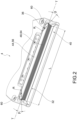
- reference numeral 4 globally denotes a reel side yarn suction nozzle.
- said reel side yarn suction nozzle 4 is applied to a winding machine 8 comprising at least one winding unit having a reel 12 in formation.
- the reel 12 in formation is obtained by winding the yarn around a relative tube 16, in a known manner.
- the yarn produced and wound into bobbins is unwound by means of special unravelling means, subjected to quality control by a sensor (yarn cleaner) and rewound by special winding means (cylinder 20) to form the reel 12.
- the yarn cleaner interrupts the winding by cutting the yarn thus generating two ends, respectively the bobbin side yarn end (not illustrated)and reel side yarn end 24.
- it is first necessary to recover the yarn ends and then join them using a special yarn-joiner.
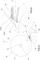
- the reel side yarn end 24 is intercepted by the reel side yarn suction nozzle 4 comprising an arm 28 movable from at least one rest position to at least one working or suction position. In the rest position, the arm 28 is in a distanced position or in any case not close to the reel 12, while in the working position the arm 28 is juxtaposed with the reel 12 in order to be able to intercept the reel side yarn end 24.
- the winding machine 8 is provided with drive means (not illustrated) for controlling the juxtaposition and distancing of the arm 28 with respect to the winding machine 12 in formation, as further described below.
- the arm 28 is fluidically connected to a suction source (not shown) to create a flow of suction air having a propagation direction X-X.
- the arm 28 terminates with a suction slit 32 having a rectilinear configuration elongated along a transverse direction T-T.
- the suction slit 32 with respect to a cross-section plane perpendicular to a first axis of rotation of the associable reel R1 and to a second axis of rotation R2 of the movable arm 28, has an upper lip 36 and a lower lip 40.
- the upper lip 36 is in a higher position, i.e., further to the side and facing the reel 12, when the arm 28 is brought into the working position. In the resting condition, the arm 28 may be rotated so as to reverse the positions of the lips.
- said upper lip 36 is set back from said lower lip 40, with respect to a propagation direction X-X of the suction air flow through the suction slit to the reel.
- the suction slit 32 has a transverse extension L, measured parallel to the transverse direction T-T, which is greater than or equal to the transverse extension of the reel 12, measured parallel to the axis of rotation of the reel R1.
- said suction slit 32 is provided with a deflector 44 and a comb 48.
- deflector 44 and the comb 48 are present together on the reel side yarn suction nozzle 4.
- the deflector 44 is oriented so as to induce a pinch of the air flow generated between the associated reel 12 and the suction slit 32, accelerating the air current and thereby facilitating the gripping of the free end of the yarn on the reel side 24.
- the deflector 44 and the comb 48 are arranged at the upper lip 36 of the suction slit 32.
- the deflector 44 and the comb 48 are arranged on opposite sides with respect to the upper lip 36; in particular, the deflector 44 faces opposite the lower lip 40, i.e., upwards when the arm 28 is in the working position, and the comb 48 faces the lower lip 40, i.e., downwards, when the arm 28 is in the working position.
- the deflector 44 and the comb 48 are arranged substantially aligned and adjacent to each other.
- the deflector 44 comprises a plate 56 having side ends provided with chamfered walls 60, i.e. inclined at an angle ⁇ ) of between 20° and 40°, preferably 30°, with respect to said transverse direction T-T.
- said chamfered walls 60 are connected with a connecting radius R of between 1 and 5 mm, preferably 3 mm, such as to prevent tangles of yarn ends at the deflector.
- the comb 48 comprises a roughened surface 64 so as to more easily retain the false yarn ends of the reel 12 before they enter the suction slit 32, so as to allow only the free yarn end to be intercepted by the comb 48.
- the comb 48 comprises a roughened surface 64 obtained by a surface roughening treatment, such as plasma treatment, at a portion of the comb 48 opposite the suction slit 32 and facing the reel 12.
- a surface roughening treatment such as plasma treatment
- the roughened surface 64 of the comb 48 has a roughness Ra of between 3 ⁇ m and 20 um.
- the roughened surface 64 has an isotropic roughness profile; in other words, no preferred direction of extension of the roughness grooves can be identified, as is the case, for example, with parallel or cross knurling.
- the roughened surface 64 extends along the entire transverse width of the comb 48, parallel to the transverse direction T-T, so as to cover the entire transverse extension of the reel 12.
- the winding machine 8 is provided with a processing and control unit (not illustrated) operatively connected to said drive means and programmed so that, during the suction phase of the reel side yarn end 24, the drive means bring the deflector 44 to a distance d from the lateral surface 52 of the reel 12 of between 1 mm and 5 mm, preferably 3 mm.
- the control of the arm position 28 by the processing and control unit may take place, for example, with the aid of an optical encoder.
- the diameter of the reel 12 in formation being known, it is possible to manage the positioning of the reel side yarn suction nozzle 4 with respect to the reel 12 so as to ensure a predetermined distance d of the deflector 44 from the lateral surface 52 of the reel 12.
- both the deflector and the comb contribute to resolving the technical problem of the present invention, since they improve the catching efficiency of the reel side yarn end.
- the deflector improves the suction capacity of the nozzle, while the rough surface of the comb makes it easier to retain the suctioned false yarn ends of the reel before they enter the suction slit, so that only the free yarn end can be intercepted by the comb.
- the two elements i.e. the deflector and the comb, cooperate synergistically with each other since the increase in the suction capacity of the suction slit enables the rough surface to better retain the false yarn ends.
Landscapes
- Engineering & Computer Science (AREA)
- Quality & Reliability (AREA)
- Textile Engineering (AREA)
- Replacing, Conveying, And Pick-Finding For Filamentary Materials (AREA)
- Spinning Methods And Devices For Manufacturing Artificial Fibers (AREA)
- Spinning Or Twisting Of Yarns (AREA)
Claims (12)
- Spulen- bzw. Rollenseitige Garnansaugdüse (4), umfassend:- einen Arm (28), der aus zumindest einer Ruheposition in zumindest eine Arbeits- oder Saugposition bewegbar ist, wobei der Arm (28) fluidisch mit einer Saugquelle verbunden ist, um einen Saugluftstrom zu erzeugen,- wobei der Arm (28) mit einem Saugschlitz (32) endet, der eine geradlinige Konfiguration aufweist, die entlang einer Querrichtung (T-T) verlängert bzw. länglich ist, wobei der Saugschlitz (32) in Bezug auf eine Querschnittsebene senkrecht zu einer ersten Drehachse (R1) der zuordenbaren bzw. dazugehörigen Spule bzw. Rolle (12) und zu einer zweiten Drehachse (R2) des beweglichen Arms (28) eine obere Lippe (36) und eine untere Lippe (40) aufweist,- dadurch gekennzeichnet, dass der Saugschlitz (32) mit einem Deflektor (44) und einem Kamm (48) versehen ist,- wobei der Deflektor (44) so ausgerichtet ist, dass er eine Einschnürung des zwischen der zugeordneten Spule (12) und dem Saugschlitz (32) erzeugten Luftstroms (32) induziert bzw. bewirkt, wodurch der Luftstrom beschleunigt wird und somit das Greifen des freien Endes des Garns auf der Spulenseite (24) erleichtert wird,- wobei der Kamm (48) eine aufgeraute Fläche bzw. Oberfläche (64) umfasst.
- Spulenseitige Garnansaugdüse (4) nach Anspruch 1, wobei der Deflektor (44) und der Kamm (48) an der oberen Lippe (36) des Saugschlitzes (32) angeordnet sind.
- Spulenseitige Garnansaugdüse (4) nach Anspruch 1 oder 2, wobei der Deflektor (44) und der Kamm (48) auf gegenüberliegenden bzw. entgegengesetzten Seiten der oberen Lippe (36) angeordnet sind, wobei der Deflektor (44) gegenüberliegend bzw. entgegengesetzt zu der unteren Lippe (40) gewandt ist bzw. von dieser abgewandt ist und der Kamm (48) der unteren Lippe (40) zugewandt ist.
- Spulenseitige Garnansaugdüse (4) nach einem der Ansprüche 1 bis 3, wobei der Deflektor (44) und der Kamm (48) im Wesentlichen ausgerichtet und angrenzend bzw. benachbart zueinander angeordnet sind.
- Spulenseitige Garnansaugdüse (4) nach einem der Ansprüche 1 bis 4, wobei die obere Lippe (36) von der unteren Lippe (40) in Bezug auf eine Ausbreitungsrichtung (X-X) des Saugluftstroms durch den Saugschlitz (32) zurückgesetzt ist.
- Spulenseitige Garnansaugdüse (4) nach einem der Ansprüche 1 bis 5, wobei der Deflektor (44) eine Platte mit Seitenenden umfasst, die mit abgeschrägten Wänden (60) versehen sind, d. h. in Bezug auf die Querrichtung (T-T) in einem Winkel (β) zwischen 20° und 40°, vorzugsweise 30°, geneigt sind.
- Spulenseitige Garnansaugdüse (4) nach Anspruch 6, wobei die abgeschrägten Wände (60) mit einem Verbindungsradius R zwischen 1 und 5 mm, vorzugsweise 3 mm, verbunden sind, um Verwicklungen von Garnenden an dem Deflektor (44) zu verhindern.
- Spulenseitige Garnansaugdüse (4) nach einem der Ansprüche 1 bis 7, wobei der Kamm (48) eine aufgeraute Fläche bzw. Oberfläche (64) umfasst, die durch eine Flächen- bzw. Oberflächenaufrauungsbehandlung erhalten wird, und zwar an einem Abschnitt des Kamms (48), der dem Saugschlitz (32) gegenüberliegt bzw. entgegengesetzt ist und der Spule (12) zugewandt ist.
- Spulenseitige Garnansaugdüse (4) nach Anspruch 8, wobei die aufgeraute Oberfläche (64) des Kamms (48) eine Rauheit Ra zwischen 3 µm und 20 µm aufweist.
- Spulenseitige Garnansaugdüse (4) nach einem der Ansprüche 8 bis 9, wobei die aufgeraute Oberfläche (64) ein isotropes Rauheitsprofil aufweist.
- Spulenseitige Garnansaugdüse (4) nach einem der Ansprüche 8 bis 10, wobei sich die aufgeraute Oberfläche (64) entlang der gesamten Querbreite des Kamms (48) parallel zu der Querrichtung (T-T) erstreckt.
- Wickelmaschine (8), umfassend zumindest eine Wickeleinheit mit einer in Bildung befindlichen Spule bzw. Rolle (12) und einer spulen- bzw. rollenseitigen Garnansaugdüse (4) nach einem der Ansprüche 1 bis 11, sowie Antriebsmittel zum Steuern bzw. Regeln der Nebeneinanderstellung und der Distanzierung bzw. des Abstands der spulenseitigen Garnansaugdüse (4) in Bezug auf die in Bildung befindliche Spule (12), wobei die Wickelmaschine (8) mit einer Verarbeitungs- und Steuer- bzw. Regeleinheit versehen ist, die operativ mit den Antriebsmitteln verbunden und so programmiert ist, dass beim Ansaugen des spulenseitigen Garnendes (24) die Antriebsmittel den Deflektor (44) auf einen Abstand d von der lateralen Fläche bzw. Oberfläche (52) der Spule (12) von zwischen 1 mm und 5 mm, vorzugsweise 3 mm, bringen.
Applications Claiming Priority (1)
| Application Number | Priority Date | Filing Date | Title |
|---|---|---|---|
| IT102021000016862A IT202100016862A1 (it) | 2021-06-28 | 2021-06-28 | Bocchetta di aspirazione filo lato rocca e relativa roccatrice provvista di detta bocchetta di aspirazione filo lato rocca |
Publications (2)
| Publication Number | Publication Date |
|---|---|
| EP4112522A1 EP4112522A1 (de) | 2023-01-04 |
| EP4112522B1 true EP4112522B1 (de) | 2024-10-02 |
Family
ID=77627418
Family Applications (1)
| Application Number | Title | Priority Date | Filing Date |
|---|---|---|---|
| EP22173698.6A Active EP4112522B1 (de) | 2021-06-28 | 2022-05-17 | Spulenseitige fadensaugdüse und spulmaschine, die mit dieser spulenseitigen fadensaugdüse versehen ist |
Country Status (3)
| Country | Link |
|---|---|
| EP (1) | EP4112522B1 (de) |
| CN (2) | CN217920800U (de) |
| IT (1) | IT202100016862A1 (de) |
Families Citing this family (1)
| Publication number | Priority date | Publication date | Assignee | Title |
|---|---|---|---|---|
| IT202100016862A1 (it) * | 2021-06-28 | 2022-12-28 | Savio Macch Tessili Spa | Bocchetta di aspirazione filo lato rocca e relativa roccatrice provvista di detta bocchetta di aspirazione filo lato rocca |
Family Cites Families (12)
| Publication number | Priority date | Publication date | Assignee | Title |
|---|---|---|---|---|
| CH334274A (de) * | 1953-11-03 | 1958-11-30 | Reiners Walter Dr Ing | Saugdüse zum Erfassen, Aufsuchen und Abheben von Fadenenden an einer Garne verarbeitenden Maschine, z. B. einer Spulmaschine |
| US2857113A (en) * | 1953-11-03 | 1958-10-21 | Reiners Walter Dr Ing | Suction nozzle for catching thread ends |
| JPS59173664U (ja) * | 1983-05-04 | 1984-11-20 | 村田機械株式会社 | 糸捲取機におけるパツケ−ジ糸端吸引保持装置 |
| GB2143548A (en) * | 1983-07-21 | 1985-02-13 | Hollingsworth | Yarn end catching |
| JPH0451476U (de) * | 1990-09-07 | 1992-04-30 | ||
| JPH0649457U (ja) * | 1992-12-16 | 1994-07-08 | 東レエンジニアリング株式会社 | サクションマウス |
| JP4147432B2 (ja) * | 2006-07-28 | 2008-09-10 | 村田機械株式会社 | 糸端引出し装置 |
| DE102011114765A1 (de) * | 2011-10-01 | 2013-04-04 | Oerlikon Textile Gmbh & Co. Kg | Kammleiste für eine Saugdüse einer Arbeitsstelle einer Kreuzspulen herstellenden Textilmaschine |
| DE102013011664A1 (de) * | 2013-07-11 | 2015-01-15 | Saurer Germany Gmbh & Co. Kg | Arbeitsstelle einer Kreuzspulen herstellenden Textilmaschine |
| JP2015044685A (ja) * | 2013-08-29 | 2015-03-12 | 村田機械株式会社 | 糸端捕捉装置及び糸巻取装置 |
| DE102015005393A1 (de) * | 2015-04-28 | 2016-11-03 | Saurer Germany Gmbh & Co. Kg | Arbeitsstelle einer Auflaufspulen herstellenden Textilmaschine |
| IT202100016862A1 (it) * | 2021-06-28 | 2022-12-28 | Savio Macch Tessili Spa | Bocchetta di aspirazione filo lato rocca e relativa roccatrice provvista di detta bocchetta di aspirazione filo lato rocca |
-
2021
- 2021-06-28 IT IT102021000016862A patent/IT202100016862A1/it unknown
-
2022
- 2022-05-17 EP EP22173698.6A patent/EP4112522B1/de active Active
- 2022-05-27 CN CN202221310209.4U patent/CN217920800U/zh active Active
- 2022-05-27 CN CN202210587827.1A patent/CN115594018A/zh active Pending
Also Published As
| Publication number | Publication date |
|---|---|
| IT202100016862A1 (it) | 2022-12-28 |
| CN217920800U (zh) | 2022-11-29 |
| EP4112522A1 (de) | 2023-01-04 |
| CN115594018A (zh) | 2023-01-13 |
Similar Documents
| Publication | Publication Date | Title |
|---|---|---|
| JP4082930B2 (ja) | 糸撚り継ぎ装置 | |
| ITMI950463A1 (it) | Dispositivo di preparazione delle estremita' dei fili per macchine tessili producenti bobine incrociate | |
| CN106319698B (zh) | 一种用于纺纱机中的纺纱区的方法及纺纱机中的纺纱区 | |
| ITMI951657A1 (it) | Dispositivo di servizio per una macchina tessile producente bobine incrociate | |
| EP4112522A1 (de) | Spulenseitige fadensaugdüse und spulmaschine, die mit dieser spulenseitigen fadensaugdüse versehen ist | |
| JP2017082375A (ja) | 作業ステーションの動作方法および作業ステーション | |
| Gandhi | Yarn preparation for weaving: winding | |
| CN108069291B (zh) | 用于将纱线端沉积在筒管上的方法、装置和纺纱卷绕机 | |
| EP1712504B1 (de) | Vorrichtung und Verfahren zum Handhaben und Steuern eines Fadens in einem Kreuzwickelkopf einer Kreuzwickelmaschine beim Auswechseln von Spulen | |
| CN110387615A (zh) | 用于线头拼接单元的线头吸提装置及其方法 | |
| EP1616829B1 (de) | Fadenführungsvorrichtung und automatische drehwickelvorrichtung | |
| EP4074639B1 (de) | Wickelmaschine mit verbessertem motorischem fadenendverlängerungshebel und zugehöriges verfahren zum steuern der position des fadenendverlängerungshebels | |
| US20250128906A1 (en) | Thread-guiding device for a workstation of a textile machine which produces cross-wound bobbins | |
| EP2574580B1 (de) | Kammleiste für eine Saugdüse einer Arbeitsstelle einer Kreuzspulen herstellenden Textilmaschine | |
| US4090676A (en) | Yarn or thread guiding device | |
| CN114852789B (zh) | 用于操作纺纱机的工作站的方法及工作站 | |
| US10400362B2 (en) | Method for depositing a yarn end on a bobbin in a defined manner, a device and a spinning and winding machine for performing the method | |
| US10577728B2 (en) | Method for preparing a workstation for resumption of the spinning process on an air-jet spinning machine, and an air-jet spinning machine for performing the method | |
| CN106400216A (zh) | 在开放端纺纱机的工作站处纺入纱线的方法及其执行装置 | |
| CN105314462A (zh) | 控制纺织机工位的捕纱嘴或清纱嘴处的负压的方法和装置 | |
| CN113213275A (zh) | 用于操作制造络纱筒的纺织机的工位的方法 | |
| CN111747233A (zh) | 用于在纺织机工位产生接纱连接的方法以及纺织机工位 | |
| CN115595700A (zh) | 用于在纱片中生成分经的整经装置和方法 | |
| CN115676499A (zh) | 用于运行纺织机的工作站的方法以及纺织机的工作站 | |
| JPS6221708B2 (de) |
Legal Events
| Date | Code | Title | Description |
|---|---|---|---|
| PUAI | Public reference made under article 153(3) epc to a published international application that has entered the european phase |
Free format text: ORIGINAL CODE: 0009012 |
|
| STAA | Information on the status of an ep patent application or granted ep patent |
Free format text: STATUS: THE APPLICATION HAS BEEN PUBLISHED |
|
| AK | Designated contracting states |
Kind code of ref document: A1 Designated state(s): AL AT BE BG CH CY CZ DE DK EE ES FI FR GB GR HR HU IE IS IT LI LT LU LV MC MK MT NL NO PL PT RO RS SE SI SK SM TR |
|
| STAA | Information on the status of an ep patent application or granted ep patent |
Free format text: STATUS: REQUEST FOR EXAMINATION WAS MADE |
|
| 17P | Request for examination filed |
Effective date: 20230328 |
|
| RBV | Designated contracting states (corrected) |
Designated state(s): AL AT BE BG CH CY CZ DE DK EE ES FI FR GB GR HR HU IE IS IT LI LT LU LV MC MK MT NL NO PL PT RO RS SE SI SK SM TR |
|
| P01 | Opt-out of the competence of the unified patent court (upc) registered |
Effective date: 20230526 |
|
| GRAP | Despatch of communication of intention to grant a patent |
Free format text: ORIGINAL CODE: EPIDOSNIGR1 |
|
| STAA | Information on the status of an ep patent application or granted ep patent |
Free format text: STATUS: GRANT OF PATENT IS INTENDED |
|
| INTG | Intention to grant announced |
Effective date: 20240625 |
|
| GRAS | Grant fee paid |
Free format text: ORIGINAL CODE: EPIDOSNIGR3 |
|
| GRAA | (expected) grant |
Free format text: ORIGINAL CODE: 0009210 |
|
| STAA | Information on the status of an ep patent application or granted ep patent |
Free format text: STATUS: THE PATENT HAS BEEN GRANTED |
|
| AK | Designated contracting states |
Kind code of ref document: B1 Designated state(s): AL AT BE BG CH CY CZ DE DK EE ES FI FR GB GR HR HU IE IS IT LI LT LU LV MC MK MT NL NO PL PT RO RS SE SI SK SM TR |
|
| REG | Reference to a national code |
Ref country code: GB Ref legal event code: FG4D |
|
| REG | Reference to a national code |
Ref country code: CH Ref legal event code: EP |
|
| REG | Reference to a national code |
Ref country code: DE Ref legal event code: R096 Ref document number: 602022006458 Country of ref document: DE |
|
| REG | Reference to a national code |
Ref country code: IE Ref legal event code: FG4D |
|
| REG | Reference to a national code |
Ref country code: LT Ref legal event code: MG9D |
|
| REG | Reference to a national code |
Ref country code: NL Ref legal event code: MP Effective date: 20241002 |
|
| REG | Reference to a national code |
Ref country code: AT Ref legal event code: MK05 Ref document number: 1728331 Country of ref document: AT Kind code of ref document: T Effective date: 20241002 |
|
| PG25 | Lapsed in a contracting state [announced via postgrant information from national office to epo] |
Ref country code: NL Free format text: LAPSE BECAUSE OF FAILURE TO SUBMIT A TRANSLATION OF THE DESCRIPTION OR TO PAY THE FEE WITHIN THE PRESCRIBED TIME-LIMIT Effective date: 20241002 |
|
| PG25 | Lapsed in a contracting state [announced via postgrant information from national office to epo] |
Ref country code: NL Free format text: LAPSE BECAUSE OF FAILURE TO SUBMIT A TRANSLATION OF THE DESCRIPTION OR TO PAY THE FEE WITHIN THE PRESCRIBED TIME-LIMIT Effective date: 20241002 |
|
| PG25 | Lapsed in a contracting state [announced via postgrant information from national office to epo] |
Ref country code: HR Free format text: LAPSE BECAUSE OF FAILURE TO SUBMIT A TRANSLATION OF THE DESCRIPTION OR TO PAY THE FEE WITHIN THE PRESCRIBED TIME-LIMIT Effective date: 20241002 Ref country code: PT Free format text: LAPSE BECAUSE OF FAILURE TO SUBMIT A TRANSLATION OF THE DESCRIPTION OR TO PAY THE FEE WITHIN THE PRESCRIBED TIME-LIMIT Effective date: 20250203 Ref country code: IS Free format text: LAPSE BECAUSE OF FAILURE TO SUBMIT A TRANSLATION OF THE DESCRIPTION OR TO PAY THE FEE WITHIN THE PRESCRIBED TIME-LIMIT Effective date: 20250202 |
|
| PG25 | Lapsed in a contracting state [announced via postgrant information from national office to epo] |
Ref country code: FI Free format text: LAPSE BECAUSE OF FAILURE TO SUBMIT A TRANSLATION OF THE DESCRIPTION OR TO PAY THE FEE WITHIN THE PRESCRIBED TIME-LIMIT Effective date: 20241002 |
|
| PG25 | Lapsed in a contracting state [announced via postgrant information from national office to epo] |
Ref country code: BG Free format text: LAPSE BECAUSE OF FAILURE TO SUBMIT A TRANSLATION OF THE DESCRIPTION OR TO PAY THE FEE WITHIN THE PRESCRIBED TIME-LIMIT Effective date: 20241002 |
|
| PG25 | Lapsed in a contracting state [announced via postgrant information from national office to epo] |
Ref country code: ES Free format text: LAPSE BECAUSE OF FAILURE TO SUBMIT A TRANSLATION OF THE DESCRIPTION OR TO PAY THE FEE WITHIN THE PRESCRIBED TIME-LIMIT Effective date: 20241002 |
|
| PG25 | Lapsed in a contracting state [announced via postgrant information from national office to epo] |
Ref country code: NO Free format text: LAPSE BECAUSE OF FAILURE TO SUBMIT A TRANSLATION OF THE DESCRIPTION OR TO PAY THE FEE WITHIN THE PRESCRIBED TIME-LIMIT Effective date: 20250102 |
|
| PG25 | Lapsed in a contracting state [announced via postgrant information from national office to epo] |
Ref country code: AT Free format text: LAPSE BECAUSE OF FAILURE TO SUBMIT A TRANSLATION OF THE DESCRIPTION OR TO PAY THE FEE WITHIN THE PRESCRIBED TIME-LIMIT Effective date: 20241002 Ref country code: LV Free format text: LAPSE BECAUSE OF FAILURE TO SUBMIT A TRANSLATION OF THE DESCRIPTION OR TO PAY THE FEE WITHIN THE PRESCRIBED TIME-LIMIT Effective date: 20241002 Ref country code: GR Free format text: LAPSE BECAUSE OF FAILURE TO SUBMIT A TRANSLATION OF THE DESCRIPTION OR TO PAY THE FEE WITHIN THE PRESCRIBED TIME-LIMIT Effective date: 20250103 |
|
| PG25 | Lapsed in a contracting state [announced via postgrant information from national office to epo] |
Ref country code: PL Free format text: LAPSE BECAUSE OF FAILURE TO SUBMIT A TRANSLATION OF THE DESCRIPTION OR TO PAY THE FEE WITHIN THE PRESCRIBED TIME-LIMIT Effective date: 20241002 Ref country code: CZ Free format text: LAPSE BECAUSE OF FAILURE TO SUBMIT A TRANSLATION OF THE DESCRIPTION OR TO PAY THE FEE WITHIN THE PRESCRIBED TIME-LIMIT Effective date: 20241002 |
|
| PG25 | Lapsed in a contracting state [announced via postgrant information from national office to epo] |
Ref country code: RS Free format text: LAPSE BECAUSE OF FAILURE TO SUBMIT A TRANSLATION OF THE DESCRIPTION OR TO PAY THE FEE WITHIN THE PRESCRIBED TIME-LIMIT Effective date: 20250102 |
|
| PG25 | Lapsed in a contracting state [announced via postgrant information from national office to epo] |
Ref country code: SM Free format text: LAPSE BECAUSE OF FAILURE TO SUBMIT A TRANSLATION OF THE DESCRIPTION OR TO PAY THE FEE WITHIN THE PRESCRIBED TIME-LIMIT Effective date: 20241002 |
|
| REG | Reference to a national code |
Ref country code: DE Ref legal event code: R097 Ref document number: 602022006458 Country of ref document: DE |
|
| PGFP | Annual fee paid to national office [announced via postgrant information from national office to epo] |
Ref country code: DE Payment date: 20250523 Year of fee payment: 4 |
|
| PG25 | Lapsed in a contracting state [announced via postgrant information from national office to epo] |
Ref country code: DK Free format text: LAPSE BECAUSE OF FAILURE TO SUBMIT A TRANSLATION OF THE DESCRIPTION OR TO PAY THE FEE WITHIN THE PRESCRIBED TIME-LIMIT Effective date: 20241002 |
|
| PG25 | Lapsed in a contracting state [announced via postgrant information from national office to epo] |
Ref country code: EE Free format text: LAPSE BECAUSE OF FAILURE TO SUBMIT A TRANSLATION OF THE DESCRIPTION OR TO PAY THE FEE WITHIN THE PRESCRIBED TIME-LIMIT Effective date: 20241002 |
|
| PG25 | Lapsed in a contracting state [announced via postgrant information from national office to epo] |
Ref country code: RO Free format text: LAPSE BECAUSE OF FAILURE TO SUBMIT A TRANSLATION OF THE DESCRIPTION OR TO PAY THE FEE WITHIN THE PRESCRIBED TIME-LIMIT Effective date: 20241002 |
|
| PG25 | Lapsed in a contracting state [announced via postgrant information from national office to epo] |
Ref country code: SK Free format text: LAPSE BECAUSE OF FAILURE TO SUBMIT A TRANSLATION OF THE DESCRIPTION OR TO PAY THE FEE WITHIN THE PRESCRIBED TIME-LIMIT Effective date: 20241002 |
|
| PGFP | Annual fee paid to national office [announced via postgrant information from national office to epo] |
Ref country code: TR Payment date: 20250512 Year of fee payment: 4 |
|
| PLBE | No opposition filed within time limit |
Free format text: ORIGINAL CODE: 0009261 |
|
| STAA | Information on the status of an ep patent application or granted ep patent |
Free format text: STATUS: NO OPPOSITION FILED WITHIN TIME LIMIT |
|
| PG25 | Lapsed in a contracting state [announced via postgrant information from national office to epo] |
Ref country code: SE Free format text: LAPSE BECAUSE OF FAILURE TO SUBMIT A TRANSLATION OF THE DESCRIPTION OR TO PAY THE FEE WITHIN THE PRESCRIBED TIME-LIMIT Effective date: 20241002 |
|
| 26N | No opposition filed |
Effective date: 20250703 |
|
| REG | Reference to a national code |
Ref country code: CH Ref legal event code: H13 Free format text: ST27 STATUS EVENT CODE: U-0-0-H10-H13 (AS PROVIDED BY THE NATIONAL OFFICE) Effective date: 20251223 |
|
| PG25 | Lapsed in a contracting state [announced via postgrant information from national office to epo] |
Ref country code: LU Free format text: LAPSE BECAUSE OF NON-PAYMENT OF DUE FEES Effective date: 20250517 |
|
| PG25 | Lapsed in a contracting state [announced via postgrant information from national office to epo] |
Ref country code: CH Free format text: LAPSE BECAUSE OF NON-PAYMENT OF DUE FEES Effective date: 20250531 |
|
| REG | Reference to a national code |
Ref country code: BE Ref legal event code: MM Effective date: 20250531 |
|
| PG25 | Lapsed in a contracting state [announced via postgrant information from national office to epo] |
Ref country code: MC Free format text: LAPSE BECAUSE OF FAILURE TO SUBMIT A TRANSLATION OF THE DESCRIPTION OR TO PAY THE FEE WITHIN THE PRESCRIBED TIME-LIMIT Effective date: 20241002 |
|
| PG25 | Lapsed in a contracting state [announced via postgrant information from national office to epo] |
Ref country code: IE Free format text: LAPSE BECAUSE OF NON-PAYMENT OF DUE FEES Effective date: 20250517 |
|
| PG25 | Lapsed in a contracting state [announced via postgrant information from national office to epo] |
Ref country code: BE Free format text: LAPSE BECAUSE OF NON-PAYMENT OF DUE FEES Effective date: 20250531 |
|
| PGFP | Annual fee paid to national office [announced via postgrant information from national office to epo] |
Ref country code: IT Payment date: 20260306 Year of fee payment: 5 |
|
| PG25 | Lapsed in a contracting state [announced via postgrant information from national office to epo] |
Ref country code: FR Free format text: LAPSE BECAUSE OF NON-PAYMENT OF DUE FEES Effective date: 20250531 |