EP4106111A1 - Elektrisches haushaltsgerät mit berührschutz für elektrische kontakte - Google Patents
Elektrisches haushaltsgerät mit berührschutz für elektrische kontakte Download PDFInfo
- Publication number
- EP4106111A1 EP4106111A1 EP22173314.0A EP22173314A EP4106111A1 EP 4106111 A1 EP4106111 A1 EP 4106111A1 EP 22173314 A EP22173314 A EP 22173314A EP 4106111 A1 EP4106111 A1 EP 4106111A1
- Authority
- EP
- European Patent Office
- Prior art keywords
- electrical
- electrical device
- bolts
- rocker
- bolt
- Prior art date
- Legal status (The legal status is an assumption and is not a legal conclusion. Google has not performed a legal analysis and makes no representation as to the accuracy of the status listed.)
- Granted
Links
Images



Classifications
-
- H—ELECTRICITY
- H01—ELECTRIC ELEMENTS
- H01R—ELECTRICALLY-CONDUCTIVE CONNECTIONS; STRUCTURAL ASSOCIATIONS OF A PLURALITY OF MUTUALLY-INSULATED ELECTRICAL CONNECTING ELEMENTS; COUPLING DEVICES; CURRENT COLLECTORS
- H01R13/00—Details of coupling devices of the kinds covered by groups H01R12/70 or H01R24/00 - H01R33/00
- H01R13/44—Means for preventing access to live contacts
- H01R13/447—Shutter or cover plate
- H01R13/453—Shutter or cover plate opened by engagement of counterpart
- H01R13/4538—Covers sliding or withdrawing in the direction of engagement
-
- H—ELECTRICITY
- H01—ELECTRIC ELEMENTS
- H01R—ELECTRICALLY-CONDUCTIVE CONNECTIONS; STRUCTURAL ASSOCIATIONS OF A PLURALITY OF MUTUALLY-INSULATED ELECTRICAL CONNECTING ELEMENTS; COUPLING DEVICES; CURRENT COLLECTORS
- H01R13/00—Details of coupling devices of the kinds covered by groups H01R12/70 or H01R24/00 - H01R33/00
- H01R13/44—Means for preventing access to live contacts
-
- A—HUMAN NECESSITIES
- A47—FURNITURE; DOMESTIC ARTICLES OR APPLIANCES; COFFEE MILLS; SPICE MILLS; SUCTION CLEANERS IN GENERAL
- A47J—KITCHEN EQUIPMENT; COFFEE MILLS; SPICE MILLS; APPARATUS FOR MAKING BEVERAGES
- A47J43/00—Implements for preparing or holding food, not provided for in other groups of this subclass
- A47J43/04—Machines for domestic use not covered elsewhere, e.g. for grinding, mixing, stirring, kneading, emulsifying, whipping or beating foodstuffs, e.g. power-driven
- A47J43/07—Parts or details, e.g. mixing tools, whipping tools
-
- A—HUMAN NECESSITIES
- A47—FURNITURE; DOMESTIC ARTICLES OR APPLIANCES; COFFEE MILLS; SPICE MILLS; SUCTION CLEANERS IN GENERAL
- A47J—KITCHEN EQUIPMENT; COFFEE MILLS; SPICE MILLS; APPARATUS FOR MAKING BEVERAGES
- A47J43/00—Implements for preparing or holding food, not provided for in other groups of this subclass
- A47J43/04—Machines for domestic use not covered elsewhere, e.g. for grinding, mixing, stirring, kneading, emulsifying, whipping or beating foodstuffs, e.g. power-driven
- A47J43/07—Parts or details, e.g. mixing tools, whipping tools
- A47J43/075—Safety devices
-
- H—ELECTRICITY
- H01—ELECTRIC ELEMENTS
- H01R—ELECTRICALLY-CONDUCTIVE CONNECTIONS; STRUCTURAL ASSOCIATIONS OF A PLURALITY OF MUTUALLY-INSULATED ELECTRICAL CONNECTING ELEMENTS; COUPLING DEVICES; CURRENT COLLECTORS
- H01R13/00—Details of coupling devices of the kinds covered by groups H01R12/70 or H01R24/00 - H01R33/00
- H01R13/46—Bases; Cases
-
- H—ELECTRICITY
- H01—ELECTRIC ELEMENTS
- H01R—ELECTRICALLY-CONDUCTIVE CONNECTIONS; STRUCTURAL ASSOCIATIONS OF A PLURALITY OF MUTUALLY-INSULATED ELECTRICAL CONNECTING ELEMENTS; COUPLING DEVICES; CURRENT COLLECTORS
- H01R13/00—Details of coupling devices of the kinds covered by groups H01R12/70 or H01R24/00 - H01R33/00
- H01R13/46—Bases; Cases
- H01R13/502—Bases; Cases composed of different pieces
-
- H—ELECTRICITY
- H01—ELECTRIC ELEMENTS
- H01R—ELECTRICALLY-CONDUCTIVE CONNECTIONS; STRUCTURAL ASSOCIATIONS OF A PLURALITY OF MUTUALLY-INSULATED ELECTRICAL CONNECTING ELEMENTS; COUPLING DEVICES; CURRENT COLLECTORS
- H01R13/00—Details of coupling devices of the kinds covered by groups H01R12/70 or H01R24/00 - H01R33/00
- H01R13/66—Structural association with built-in electrical component
- H01R13/665—Structural association with built-in electrical component with built-in electronic circuit
-
- H—ELECTRICITY
- H01—ELECTRIC ELEMENTS
- H01R—ELECTRICALLY-CONDUCTIVE CONNECTIONS; STRUCTURAL ASSOCIATIONS OF A PLURALITY OF MUTUALLY-INSULATED ELECTRICAL CONNECTING ELEMENTS; COUPLING DEVICES; CURRENT COLLECTORS
- H01R24/00—Two-part coupling devices, or either of their cooperating parts, characterised by their overall structure
- H01R24/76—Two-part coupling devices, or either of their cooperating parts, characterised by their overall structure with sockets, clips or analogous contacts and secured to apparatus or structure, e.g. to a wall
-
- H—ELECTRICITY
- H01—ELECTRIC ELEMENTS
- H01R—ELECTRICALLY-CONDUCTIVE CONNECTIONS; STRUCTURAL ASSOCIATIONS OF A PLURALITY OF MUTUALLY-INSULATED ELECTRICAL CONNECTING ELEMENTS; COUPLING DEVICES; CURRENT COLLECTORS
- H01R24/00—Two-part coupling devices, or either of their cooperating parts, characterised by their overall structure
- H01R24/76—Two-part coupling devices, or either of their cooperating parts, characterised by their overall structure with sockets, clips or analogous contacts and secured to apparatus or structure, e.g. to a wall
- H01R24/78—Two-part coupling devices, or either of their cooperating parts, characterised by their overall structure with sockets, clips or analogous contacts and secured to apparatus or structure, e.g. to a wall with additional earth or shield contacts
-
- H—ELECTRICITY
- H01—ELECTRIC ELEMENTS
- H01R—ELECTRICALLY-CONDUCTIVE CONNECTIONS; STRUCTURAL ASSOCIATIONS OF A PLURALITY OF MUTUALLY-INSULATED ELECTRICAL CONNECTING ELEMENTS; COUPLING DEVICES; CURRENT COLLECTORS
- H01R2103/00—Two poles
-
- H—ELECTRICITY
- H01—ELECTRIC ELEMENTS
- H01R—ELECTRICALLY-CONDUCTIVE CONNECTIONS; STRUCTURAL ASSOCIATIONS OF A PLURALITY OF MUTUALLY-INSULATED ELECTRICAL CONNECTING ELEMENTS; COUPLING DEVICES; CURRENT COLLECTORS
- H01R2201/00—Connectors or connections adapted for particular applications
-
- H—ELECTRICITY
- H01—ELECTRIC ELEMENTS
- H01R—ELECTRICALLY-CONDUCTIVE CONNECTIONS; STRUCTURAL ASSOCIATIONS OF A PLURALITY OF MUTUALLY-INSULATED ELECTRICAL CONNECTING ELEMENTS; COUPLING DEVICES; CURRENT COLLECTORS
- H01R24/00—Two-part coupling devices, or either of their cooperating parts, characterised by their overall structure
- H01R24/66—Two-part coupling devices, or either of their cooperating parts, characterised by their overall structure with pins, blades or analogous contacts and secured to apparatus or structure, e.g. to a wall
- H01R24/68—Two-part coupling devices, or either of their cooperating parts, characterised by their overall structure with pins, blades or analogous contacts and secured to apparatus or structure, e.g. to a wall mounted on directly pluggable apparatus
Definitions
- the invention relates to an electrical device with protection against accidental contact for electrical contacts.
- the electrical device is in particular an electrical household appliance.
- Thermomix Friend ® There is an electrical household appliance called the Thermomix Friend ® .
- This household appliance is the subject of European patent application with the official file number 20175328.2 .
- the household appliance Thermomix Friend ® comprises a stand and a vessel with a stirring tool inside.
- the vessel can be inserted into the standing part.
- the vessel includes an electrical heater and electrical plugs connected to the heater.
- the electrical plugs protrude downwards from the bottom of the vessel.
- the stand includes electrical sockets into which the receptacle's electrical plugs are inserted when the receptacle is inserted into the stand.
- the electrical heating device can then be supplied with power for heating via the standing part.
- the invention also relates to such an electrical household appliance.
- the aim of the present invention is to protect such electrical sockets, ie electrical contacts, from accidental contact.
- an electrical device comprises the features of the first claim.
- Advantageous configurations emerge from the dependent claims.
- the electrical device is in particular an electrical household appliance.
- the electrical device includes electrical contacts and access to the electrical contacts for making an electrical plug connection.
- An electrical device is a device that requires electricity to operate.
- the electrical device may include an electric motor.
- the electrical device can include an electronic controller.
- the electrical device can include an input device in order to be able to operate electrical components of the electrical device.
- the electrical device can include a switch as an input device.
- the electrical device can include a touch-sensitive display as an input device.
- the electronic device can include a microphone and voice recognition as an input device.
- the electrical device can include an output device in order to be able to output information, for example on the operation of the electrical device.
- a display can be provided as the output device.
- a loudspeaker can be present as the output device.
- the electrical device may include a battery to be powered.
- the electronic device can include a cable and a plug that can be connected to an external power source for supplying power to the electronic device.
- the electrical device is a household device, it is a device that is intended and suitable for use in a private household.
- it can be a food processor with which a meal can be prepared.
- the electrical contacts are intended and suitable for being connected to other electrical contacts. There is therefore access to every electrical contact.
- the electrical contacts can be electrically contacted by other electrical contacts through the accesses.
- the electrical insulation consists in particular of plastic.
- the electrical insulation completely covers the electrical contacts in such a way that the electrical contacts can no longer be reached with the finger of a normally large hand of an adult and/or a child.
- the entrance leading to an electrical contact therefore has a diameter of no more than 5 mm at its narrowest point, so that even a child's finger cannot touch the electrical contact.
- a bolt is an elongated object that can pass through an electrical contact.
- a bolt is at least essentially pin-shaped. Because a bolt is part of the electrical insulation, the bolt is made of an electrically insulating material such as plastic.
- Each bolt can be in an electrically isolating position. In the electrically isolating position, the bolt prevents the associated electrical contact from being accessible through the access for another electrical contact. If a bolt is in its electrically insulating position, there can be no electrical contact with another electrical contact. The bolt must therefore be moved out of its electrically insulating position so that another electrical contact can make electrical contact with the electrical contact belonging to the bolt. If a bolt is in its isolating position, it is passed through its associated electrical contact in the sense of the present invention.
- the bolts can be moved independently of each other. However, the bolts can only be moved from the electrically isolating position to an electrically non-isolating position if the two bolts are moved together. If a bolt is pressed in the direction of its electrical contact using a pin, seen from the outside, the bolt cannot leave its electrically insulating position if the other bolt is not pressed in the direction of its electrical contact at the same time. For example, a child cannot use an electrically conductive pencil to move a single bolt in such a way that the child could use the pencil to make electrical contact with the bolt's electrical contact.
- Optical means may be provided to detect when only one bolt is moved towards its electrical contact as seen from the outside.
- a blocking element can be moved into a blocking position by the optical device if the optical device detects that only one bolt is moved by pressing. In the blocking position, the blocking element prevents the bolt from being able to leave its electrically insulating position.
- a seesaw which can be pivoted by moving only one bolt. If the bolts are alternately moved back and forth, the seesaw will rock.
- a seesaw means an elongated object that can be pivoted and rocked like a seesaw.
- the optical device can detect a pivoting movement of the rocker in order to then trigger the blocking.
- the rocker means that it can be reliably detected in a technically simple manner when only one bolt is being moved.
- Ends of the rocker can be pivotally connected to ends of the bolts so as to ensure that the rocker is pivoted only when only one bolt is moved towards the non-isolating position.
- Ends of the bolts can only rest on the rocker in order to ensure that the rocker is only pivoted when only one bolt is moved towards the non-isolating position. This minimizes the manufacturing effort.
- a central area of the rocker can be held by a spring.
- the rocker can be moved in the direction of the spring against the force of the spring.
- the rocker can therefore be both pivoted and moved in the direction of the spring without a pivoting movement.
- the rocker can then be moved back towards the starting position by the spring. This also allows the bolts to be moved back into the isolating position by the force of the spring. In this configuration, a single spring is sufficient to be able to move a plurality of bolts back into the starting position.
- the spring is an elastically deformable body.
- the spring is preferably made of metal.
- the spring can also be made of plastic, for example.
- a helical spring is to be preferred because it can be mounted and held particularly easily with little installation space.
- the spring can be leaf-shaped, for example.
- the bolts can be moved along the vertical when the electrical device is set up as intended. Desired movements can thus advantageously be supported by gravity. Undesirable forces due to gravity can be avoided.
- the bolts can be moved vertically through an electrical shield.
- the electrical shield is part of the electrical insulation that protects against touching the electrical contacts.
- the electrical shielding can be a housing of the electrical device made of plastic, for example.
- a spring can be provided for each bolt, which can move the associated bolt into the electrically non-insulating position and hold it in this position.
- this embodiment has the disadvantage that a plurality of springs must be used.
- a rod i.e. an elongated object, can be connected to the seesaw and protrude from the seesaw.
- the rod preferably protrudes from a central region of the seesaw. If the seesaw is pivoted, the rod is also pivoted. Pivoting movement of the wand may cause a switch to be actuated. If the switch is actuated, a blocking element can thereby be moved into a blocking position. In the blocking position, the blocking element blocks a bolt from being moved out of its isolating position.
- the rod or one end of the rod can be pivoted to a blockage area. If the rod or its end has been pivoted to the blocking area, the rod cannot be moved any further out of its isolating position.
- the blocking surface is a surface which prevents the bolt from moving out of its isolating position when the rod has been pivoted towards the blocking surface.
- the blocking surface is preferably a flat surface that is flat and has no bulges. However, the blocking surface can also be curved. This prevents a bolt from being moved out of its isolating position in a technically very simple and reliable manner.
- a step or an indentation comprises the blocking area.
- the step or indentation ensures that the rod pivoted to the blocking surface cannot leave the blocking position unplanned. In particular, it can be avoided that the rod can be pivoted beyond the blockage area.
- the step includes a flat blocking surface and a further flat surface protruding therefrom. The other area generally protrudes perpendicularly or at least essentially perpendicularly from the blocking surface.
- An indentation means an inwardly curved shape.
- a bolt is connected to another bolt by a connecting element.
- the connecting element can be a rod, for example.
- connection is meant a fixed connection.
- the connecting element can be manufactured in one piece with the bolts in one work step, for example by plastic injection molding.
- the additional bolt is part of an electrical insulation for an additional electrical contact. This configuration is particularly advantageous if at least three current-carrying electrical contacts are to be protected by bolts from being accidentally touched, since the number of components and thus also the installation space can be kept particularly small.
- a bolt is preferably connected to a guide element that is guided by a guide rail. Reliable functioning is ensured by guiding the bolt.
- the rail is preferably U-shaped in section.
- the guide element can then extend into the U-shape for guidance. Two opposing guide rails can be provided for each guide element in order to guide the bolt particularly reliably.
- the guide element can also be bordered. The border then forms a guide rail in the sense of the present invention, since the border guides the guide element.
- the guiding element can be a plate.
- a plate is particularly suitable for being guided stably and evenly by two opposing guide rails.
- a plate can ensure a suitably low center of gravity in order to be able to suitably guide a bolt attached to it.
- Bolt and plate are preferably made in one piece in one operation, for example by injection molding.
- Bolt and plate can be made of plastic.
- a housing part made of plastic preferably comprises the guide rail for the guide element and/or the access for each electrical contact.
- Such a housing part can be manufactured in one piece, for example from plastic, for example by injection molding, which advantageously keeps the number of parts and thus the assembly effort and installation space low.
- At least one further rod is preferably attached to the seesaw and is held by at least one holding rail. The position of the rocker is thus stabilized. This is for operational safety.
- a half-shell is preferably present, which encompasses the holding rail and/or a blocking surface and/or a holder for holding the spring.
- Such a half-shell can be manufactured in one piece in one work step. This can be done, for example, by injection molding.
- the half-shell can be made of plastic. The number of parts is advantageously minimized in this way, and with it the assembly work and installation space.
- the electrical device is preferably a stand-alone part of a mixer.
- a stirring device within the meaning of the present invention comprises, in addition to the standing part, a vessel in which a meal can be prepared by heating and/or stirring.
- the vessel can be connected to the standing part.
- a dish can then be heated and/or processed with a mixing tool.
- Standing part therefore means the part of a mixer which is intended to be set up on a base, for example on a worktop.
- a standing part can therefore have, for example, protruding nubs on its underside.
- the vessel can be inserted into a recess of the standing part.
- the stirring tool can be present in the bottom of the vessel.
- the stirring tool can be connected to a shaft that passes through the bottom of the vessel.
- the shaft can be connected via a coupling to the shaft of an electric motor that is present in the standing part.
- the vessel comprises a heating device and therefore electrical contacts for the purpose of power supply, which are to be supplied with power via electrical contacts of the standing part.
- the electrical contacts of the vessel are connected to the electrical contacts of the standing part when the vessel is connected to the standing part, ie, for example, is inserted into a recess of the standing part provided for this purpose.
- the electrical contacts of the vessel are usually electrical plugs.
- the electrical contacts of the vessel may extend downward from the bottom of the vessel.
- the electrical contacts of the vessel are of different lengths.
- the length of the bolts is correspondingly different. If, for example, an electrical plug arranged on the right is shorter than an electrical plug arranged on the left of the vessel, then the bolt of the standing part arranged on the right is correspondingly longer than the bolt of the standing part arranged on the left. Coding can thus be achieved by bolts of different lengths or electrical contacts of different lengths. This improves security against accidental touching of contacts. This applies e.g. This is because uncoded third-party devices cannot be electrically connected to the electrical contacts of the standing part. This also applies independently of the standing part and vessel. Two bolts of an electrical device are therefore advantageously of different lengths for coding reasons, in order to ensure that an electrical connection is only possible with corresponding electrical devices that are correspondingly coded.
- the stirring device is preferably designed such that the maximum possible rotational speed of the stirring tool is 1000 revolutions per minute at which the stirring device can turn the stirring tool.
- the maximum possible rotational speed at which the stirring device can rotate the stirring tool is preferably no more than 400 revolutions per minute.
- the mixer can also rotate at speeds of, for example, at least 5000 revolutions per minute if it is not to be particularly small. To avoid overloading, the speed should not exceed 20,000 revolutions per minute.
- the invention relates to an electrical connector of an electrical device in order to be able to produce an electrical plug-in connection.
- the invention can therefore only relate to an electrical connector of an electrical plug-in connection.
- Such a connector would then consequently comprise: electrical contacts, access points to the electrical contacts for making an electrical plug connection, electrical insulation which protects the electrical contacts from being touched, at least two bolts as part of the electrical insulation which are in an electrically isolating position are passed through the electrical contacts, the bolts being able to be moved independently of one another, the bolts further from the electrically isolating position can only be moved into an electrically non-isolating position if the two bolts are moved together.
- electrical connectors can be designed as described.
- the figure 1 shows electrical contacts 1 of a standing part.
- the electrical contacts 1 are set up in such a way that they can be connected to electrical contacts which protrude downwards from the bottom of a vessel.
- the electrical contacts are three metal electrical sockets 1, which are held by a plastic housing part 2, only partially shown, of the standing part.
- Each electrical socket 1 has an upwardly tapering, clamp-like base part 3 .
- the opposite arms of the base 3 can be elastically bent.
- At the top of each base part 3 there is a widening 4 which facilitates the insertion of an electrical plug.
- the widening 4 can be formed by small plates at the upper end of the arms.
- Each widening 4 borders on the upper side of the housing part 2 made of plastic, so that the housing part 2 helps to protect against accidental touching of the electrical sockets 1 .
- the electrical contacts 1 are also covered on the sides and on their underside by components made of plastic and are therefore protected against accidental contact.
- the electrical contacts 1 can be crimp contacts.
- the middle electrical socket 1 is a protective earth contact. No additional measures are therefore required to protect against touching the central electrical socket 1 .
- the two outer electrical sockets 1 are live and therefore equipped with a separate protection against accidental contact.
- Each protection against accidental contact for the two outer electrical sockets 1 comprises a bolt 5 made of plastic.
- Each bolt 5 is passed through a current-carrying electrical socket 1 and protrudes from the associated socket 1 both at the top and at the bottom. At the top, the bolt 5 protects against accidental touching of the associated electrical contact 1.
- Each bolt 5 includes a widening 6. The widening 6 is located in the in the figure 1 shown starting position within the upwardly tapering base part 3.
- the lower ends of the two bolts 1 are connected to one another by a rocker 7 or at least rest on the upper side of the rocker 7 .
- the ends of the rocker 7 can be pivotally connected to the lower ends of the bolts 5 or the lower ends of the two bolts 1 can rest on the ends of the rocker 7.
- the rocker 7 can therefore be pivoted. There is such a contact between the rocker 7 and the pin 5 that the rocker 7 pushes the pin 5 upwards and the rocker 7 can be pivoted by moving a pin 5 .
- the rocker 7 can be lowered by the two bolts 5.
- a preloaded spring 8 presses against the underside of the rocker 7. With the help of the spring 8 and the rocker 7, the widened portions 6 of the bolts 5 are pressed against the base part 3, which tapers upwards.
- the bolts 1 are characterized in their in the figure 1 shown starting position held.
- a rod 9 protrudes vertically downwards from the rocker 7 .
- the rod 9 is arranged in a central area of the seesaw 7 .
- the lower end of the rod 9 is located above a space 10 which is delimited by two limits 11.
- the tops of the limitations 11 have opposite steps 12 .
- the steps 12 include a horizontal blocking surface and a surface projecting upwardly from the blocking surface, typically vertically.
- the figure 2 shows a bolt 5 on the right side, compared to figure 1 has been pressed against the force of the spring 8 down. Since the bolt 5 shown on the left is still in its electrically insulating starting position, the rocker 7 has been pivoted downwards on the right-hand side. The rod 9 has thereby been pivoted into the stage 12 shown on the left. The bolt 5 shown on the right can therefore not be moved further down.
- the electrical socket 1 shown on the right cannot be touched as before, because this is prevented by the bolt 5 still projecting upwards and the housing part 2 adjoining it, which continue to shield the electrical socket 5 shown on the right from the outside.
- the bolt 5 shown on the right cannot be moved out of its electrically insulating position.
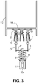
- a vessel 13 with a bottom 14 is sketched in section. Electrical plugs 15 project downwards from the floor 14 .
- the vessel 13 is inserted into a recess 16 of the standing part.
- the recess 16 can be connected to the housing part 2 in one piece. However, the recess 16 can also be a part that is separate from the housing part 2 .
- the electrical plugs 15 pressed the bolts 5 down at the same time. Therefore, the rocker 7 is only lowered against the force of the spring 8, but has not been pivoted. The rod 9 was therefore not pivoted into a stage 12. The rocker 7 could therefore be lowered so that the connector 15 as in the figure 3 shown contact the sockets 1 electrically.
- the Figures 1 to 3 thus show electrical contacts 1 of a household appliance with access for electrical contacts 15 of a vessel 13 for producing an electrical plug connection.
- electrical insulation 2, 5, which protects the electrical contacts 1 from being touched.
- Two bolts 5 are part of the electrical insulation. The bolts 5 can only be moved from an electrically isolating position to an electrically non-isolating position if the two bolts 5 are moved together.
- a preferred embodiment of the rocker 7 is shown. This includes two bearing surfaces 17. The bearing surfaces 17 partially have a border 18 on.
- the rod 9 is arranged to the side of the rocker 7 and is integrally connected to a central area of the rocker 7 .
- the rod 9 has therefore been produced in one work step together with the rocker 7, for example by plastic injection molding.
- the spring 8 extends with one end into a cylinder-like Recess 19 of the rocker 7 inside.
- the cylindrical recess 19 is open at the bottom.
- the rocker 7 can, for example, have two further rods 29 reaching down, which can, however, be arranged in such a way that they cannot reach into a step 12 for a blockage. Instead, the other rods 29 can be guided, for example, by holding rails in order to stabilize the position of the rocker 7.
- the rocker 7 is shown together with an embodiment of two bolts 5. Projections 20 of the bolts 5 rest on the bearing surfaces 17 of the rocker 7 and extend into the borders 18 . Each border 18 of the rocker 7 therefore contributes to securing the position of the bolt 5. If a bolt 5 is pressed down, it thus presses down the contact surface 17 of the rocker 7 . Press both bolts 5 down at the same time, the rocker 7 is lowered down. If only one bolt 4 is pressed down, only one end area of the rocker 7 is lowered and the rocker 7 is therefore pivoted. The bolts can be moved back into their initial position by the force of the spring 8 .
- the bolts 5 are integrally connected to a plate 21 on their underside.
- the plate 21 serves to guide the bolt 5 in order to be able to move it up and down reliably.
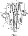
- FIG. 6 shows an embodiment in the cut-open state with the bolts 5 figure 5 and the rocker 7 from the Figures 4 and 5 .
- a half-shell 22 made of plastic on the underside comprises the steps 12 and the space 10 for the rod 9.
- the half-shell 22 can hold the underside of the spring 8.
- the half-shell 22 can have a U-shaped cross-section holding rails 26 for the rods 29 of the rocker 7.
- the holding rails surround the rods 29 at such a distance that a desired pivoting movement of the rocker 7 is not prevented by the holding rails 26 .
- the half-shell 22 comprises a cylindrical holder 30 for holding the lower end of the spring 8.
- a housing part 2 is seated on the upper side of the half-shell 22.
- the housing part 2 includes guide rails 23 for the plates 21.
- each socket 1, in addition to two arms with the flared portions 4, can also include a further arm 24 for electrical contacting.
- the other arm 24 can as in the figure 6 pointed backwards staggered and otherwise between the two arms that form the flare 4, arranged.
- the electrical sockets 1 are held by the housing part 2 .
- the electrical contacts can each have a lateral connection 25 .
- the side connections can be connected to a power source via additional electrical conductors.
- the housing part 2 has funnel-shaped entry openings 27 on the upper side above the sockets 1 for the simple insertion of electrical plugs 15 .
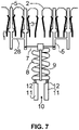
- FIG 7 an example with five contacts 1 is shown.
- Four of the five contacts are live contacts. Therefore, 1 pin 5 is passed through four contacts.
- the bolts 5 are connected to one another in pairs by a connecting element 28 which is in the form of a rod, for example.
- the connecting elements 28 are located below the contacts 1.
- Each pair of the bolts 5 behaves as a single bolt 5 from figure 1 . If only bolt 5 and thus only one pair of bolts is depressed, this movement is blocked as soon as the rod 9 has been pivoted into a stage 12. If both pairs of bolts are pressed down at the same time, ie together, the rod 9 is not pivoted into a step 12 and the electrical contacts 1 can be electrically contacted by electrical plugs.
- a stirring device is shown with a standing part 31 and a vessel 13 which is inserted into a recess 32 of the standing part 31 .
- the standing part has a display 33 and a rotary knob 34.
- the vessel 13 can be removed from the recess 32 using the handle 35.
- the vessel 13 and the standing part 31 are electrically connected to one another via a plug connection, as shown in FIG figure 3 will be shown.
Landscapes
- Engineering & Computer Science (AREA)
- Mechanical Engineering (AREA)
- Food Science & Technology (AREA)
- Microelectronics & Electronic Packaging (AREA)
- Details Of Connecting Devices For Male And Female Coupling (AREA)
- Connections Arranged To Contact A Plurality Of Conductors (AREA)
Abstract
Description
- Die Erfindung betrifft ein Elektrogerät mit Berührschutz für elektrische Kontakte. Das Elektrogerät ist insbesondere ein elektrisches Haushaltsgerät.
- Es gibt ein elektrisches Haushaltsgerät mit der Bezeichnung Thermomix Friend®. Dieses Haushaltsgerät ist Gegenstand der
europäischen Patentanmeldung mit dem amtlichen Aktenzeichen 20175328.2 - Mit der vorliegenden Erfindung wird angestrebt, solche elektrischen Buchsen, also elektrische Kontakte, vor unplanmäßigen Berührungen zu schützen.
- Um dieses Ziel zu erreichen, umfasst ein Elektrogerät die Merkmale des ersten Anspruchs. Vorteilhafte Ausgestaltungen ergeben sich aus den abhängigen Ansprüchen.
- Das Elektrogerät ist insbesondere ein elektrisches Haushaltsgerät. Das Elektrogerät umfasst elektrische Kontakte und einen Zugang zu den elektrischen Kontakten zur Herstellung einer elektrischen Steckverbindung. Es gibt eine elektrische Isolierung, die vor einer Berührung der elektrischen Kontakte schützt. Es gibt zumindest zwei Bolzen als Teil der elektrischen Isolierung. In einer elektrisch isolierenden Stellung sind die Bolzen durch die elektrischen Konakte hindurchgeführt. Die Bolzen können unabhängig voneinander bewegt werden. Die Bolzen können von der elektrisch isolierenden Stellung in eine elektrisch nicht isolierende Stellung nur dann bewegt werden, wenn die beiden Bolzen gemeinsam bewegt werden.
- Ein Elektrogerät ist ein Gerät, welches für seinen Betrieb elektrischen Strom benötigt. Das Elektrogerät kann einen elektrischen Motor umfassen. Das Elektrogerät kann eine elektronische Steuerung umfassen. Das Elektrogerät kann eine Eingabeeinrichtung umfassen, um elektrische Komponenten des Elektrogeräts bedienen zu können. Das Elektrogerät kann als Eingabeeinrichtung einen Schalter umfassen. Das Elektrogerät kann als Eingabeeinrichtung ein berührungsempfindliches Display umfassen. Das Elektrogerät kann als Eingabeeinrichtung ein Mikrofon und eine Spracherkennung umfassen.
- Das Elektrogerät kann eine Ausgabeeinrichtung umfassen, um Informationen beispielsweise zum Betrieb des Elektrogeräts ausgeben zu können. Als Ausgabeeinrichtung kann ein Display vorgesehen sein. Als Ausgabeeinrichtung kann ein Lautsprecher vorhanden sein.
- Das Elektrogerät kann eine Batterie umfassen, um mit Strom versorgt zu werden. Das Elektrogerät kann ein Kabel und einen Stecker umfassen, der mit einer externen Stromquelle für eine Stromversorgung des Elektrogeräts verbunden werden kann.
- Ist das Elektrogerät ein Haushaltsgerät, so ist es ein Gerät, welches dafür bestimmt und geeignet ist, in einem privaten Haushalt eingesetzt zu werden. Es kann sich also beispielsweise um eine Küchenmaschine handeln, mit der eine Speise zubereitet werden kann.
- Die elektrischen Kontakte sind dafür bestimmt und geeignet, um mit anderen elektrischen Kontakten verbunden zu werden. Es gibt daher zu jedem elektrischen Kontakt einen Zugang. Durch die Zugänge hindurch können die elektrischen Kontakte durch andere elektrische Kontakte elektrisch kontaktiert werden.
- Es gibt eine elektrische Isolierung, die vor einer Berührung der elektrischen Kontakte schützt. Die elektrische Isolierung besteht insbesondere aus Kunststoff. Die elektrische Isolierung deckt die elektrischen Kontakte insbesondere derart vollständig ab, dass die elektrischen Kontakte nicht mehr mit dem Finger einer üblich großen Hand einer erwachsenen Person und/oder eines Kindes erreicht werden können. Der Zugang, der zu einem elektrischen Kontakt führt, weist daher beispielsweise an seiner engsten Stelle einen Durchmesser von nicht mehr als 5 mm auf, damit auch ein Finger eines Kindes den elektrischen Kontakt nicht berühren kann.
- Ein Bolzen ist ein länglicher Gegenstand, der durch einen elektrischen Kontakt hindurchreichen kann. Ein Bolzen ist zumindest im Wesentlichen stiftförmig. Da ein Bolzen Teil der elektrischen Isolierung ist, besteht der Bolzen aus einem elektrisch isolierenden Material wie Kunststoff.
- Ein jeder Bolzen kann sich in einer elektrisch isolierenden Stellung befinden. In der elektrisch isolierenden Stellung verhindert der Bolzen, dass der zugehörige elektrische Kontakt durch den Zugang hindurch für einen anderen elektrischen Kontakt erreichbar ist. Befindet sich ein Bolzen in seiner elektrisch isolierenden Stellung, so kann kein elektrischer Kontakt zu einem anderen elektrischen Kontakt vorliegen. Der Bolzen muss also aus seiner elektrisch isolierenden Stellung heraus bewegt werden, damit ein anderer elektrischer Kontakt den zum Bolzen gehörenden elektrischen Kontakt elektrisch kontaktieren kann. Befindet sich ein Bolzen in seiner isolierenden Stellung, so ist dieser im Sinne der vorliegenden Erfindung durch seinen zugehörigen elektrischen Kontakt hindurchgeführt.
- Die Bolzen können unabhängig voneinander bewegt werden. Die Bolzen können von der elektrisch isolierenden Stellung in eine elektrisch nicht isolierende Stellung allerdings nur dann bewegt werden, wenn die beiden Bolzen gemeinsam bewegt werden. Wird also ein Bolzen mithilfe eines Stiftes von außen gesehen in Richtung seines elektrischen Kontakts gedrückt, so kann der Bolzen seine elektrisch isolierende Stellung nicht verlassen, wenn nicht zeitgleich auch der andere Bolzen in Richtung seines elektrischen Kontaktes gedrückt wird. Ein Kind kann also beispielsweise nicht mithilfe eines elektrisch leitenden Stiftes einen einzelnen Bolzen so bewegen, dass das Kind mithilfe des Stiftes einen elektrischen Kontakt zum elektrischen Kontakt des Bolzens herstellen könnte.
- Es kann eine optische Einrichtung vorhanden sein, mit der erkannt wird, wenn nur ein Bolzen von außen gesehen in Richtung seines elektrischen Kontakts bewegt wird. Durch die optische Einrichtung kann ein Blockadeelement in eine blockierende Stellung bewegt werden, wenn die optische Einrichtung erkennt, dass nur ein Bolzen durch Drücken bewegt wird. In der blockierenden Stellung verhindert das Blockadeelement, dass der Bolzen seine elektrisch isolierende Stellung verlassen kann.
- In einer Ausgestaltung ist eine Wippe vorhanden, die durch Bewegen von nur einem Bolzen verschwenkt werden kann. Werden die Bolzen abwechselnd hin und her bewegt, so wippt die Wippe. Mit Wippe ist ein länglicher Gegenstand gemeint, der verschwenkt werden und ähnlich wie eine Wippe wippen kann. Die optische Einrichtung kann eine Schwenkbewegung der Wippe erkennen, um dann das Blockieren auszulösen. Durch die Wippe wird also erreicht, dass auf eine technisch einfache Weise zuverlässig erkannt werden kann, wenn nur ein Bolzen bewegt wird.
- Enden der Wippe können mit Enden der Bolzen drehbeweglich verbunden sein, um so zu erreichen, dass die Wippe nur dann verschwenkt wird, wenn nur ein Bolzen in Richtung nicht isolierende Stellung bewegt wird.
- Enden der Bolzen können auf der Wippe lediglich aufliegen, um so zu erreichen, dass die Wippe nur dann verschwenkt wird, wenn nur ein Bolzen in Richtung nicht isolierende Stellung bewegt wird. Dies minimiert den Herstellungsaufwand.
- Ein mittlerer Bereich der Wippe kann durch eine Feder gehalten werden. Die Wippe kann gegen die Kraft der Feder in Richtung Feder bewegt werden. Die Wippe kann daher sowohl verschwenkt als auch ohne eine Schwenkbewegung in Richtung der Feder bewegt werden. Außerdem kann die Wippe anschließend durch die Feder in Richtung Ausgangsstellung zurückbewegt werden. Dadurch können auch die Bolzen in die isolierende Stellung durch die Kraft der Feder zurückbewegt werden. Bei dieser Ausgestaltung genügt eine einzige Feder, um eine Mehrzahl von Bolzen zurück in die Ausgangsstellung bewegen zu können.
- Die Feder ist ein elastisch verformbarer Körper. Die Feder besteht aus Stabilitätsgründen vorzugsweise aus Metall. Die Feder kann aber auch beispielsweise aus Kunststoff gefertigt sein. Eine spiralförmige Feder ist zu bevorzugen, da diese besonders einfach mit geringem Bauraum montiert und gehalten werden kann. Die Feder kann aber beispielsweise blattförmig sein.
- In einer Ausgestaltung der Erfindung können die Bolzen entlang der Vertikalen bewegt werden, wenn das Elektrogerät bestimmungsgemäß aufgestellt ist. Erwünschte Bewegungen können dadurch vorteilhaft durch Schwerkraft unterstützt werden. Unerwünschte Kräfte aufgrund von Schwerkraft können vermieden werden.
- Die Bolzen können insbesondere vertikal durch eine elektrische Abschirmung hindurch bewegt werden. Die elektrische Abschirmung ist Teil der elektrischen Isolierung, die vor einer Berührung der elektrischen Kontakte schützt. Die elektrische Abschirmung kann ein beispielsweise aus Kunststoff bestehendes Gehäuse des Elektrogeräts sein. In einer Ausgestaltung kann für jeden Bolzen eine Feder vorgesehen sein, die jeweils den zugehörigen Bolzen in die elektrisch nicht isolierende Stellung bewegen und in dieser Stellung halten kann. Diese Ausgestaltung ist aber im Vergleich zur vorhergehenden Ausgestaltung mit dem Nachteil verbunden, eine Mehrzahl von Federn einsetzen zu müssen.
- Ein Stab, also ein länglicher Gegenstand, kann mit der Wippe verbunden sein und von der Wippe abstehen. Vorzugsweise steht der Stab von einem mittleren Bereich der Wippe ab. Wird die Wippe verschwenkt, so wird auch der Stab verschwenkt. Eine Schwenkbewegung des Stabs kann bewirken, dass ein Schalter betätigt wird. Wird der Schalter betätigt, so kann dadurch ein Blockadeelement in eine blockierende Stellung bewegt werden. In der blockierenden Stellung blockiert das Blockadeelement das Herausbewegen eines Bolzens aus seiner isolierenden Stellung.
- Der Stab bzw. ein Ende des Stabs kann in einer Ausgestaltung zu einer Blockadefläche geschwenkt werden. Ist der Stab bzw. sein Ende zur Blockadefläche geschwenkt worden, so kann der Stab nicht weiter aus seiner isolierenden Stellung herausbewegt werden. Die Blockadefläche ist also eine Fläche, die das Herausbewegen des Bolzens aus seiner isolierenden Stellung verhindert, wenn der Stab zur Blockadefläche geschwenkt worden ist. Die Blockadefläche ist aus Fertigungsgründen vorzugsweise eine plane Fläche, die eben ist und keine Wölbungen aufweist. Die Blockadefläche kann aber auch gewölbt sein. Hierdurch wird auf technisch sehr einfache und zuverlässige Weise verhindert, dass ein Bolzen aus seiner isolierenden Stellung bewegt wird.
- In einer Ausgestaltung umfasst eine Stufe oder eine Einbuchtung die Blockadefläche. Durch die Stufe bzw. Einbuchtung wird verbessert sichergestellt, dass der zur Blockadefläche geschwenkte Stab die blockierende Stellung nicht unplanmäßig verlassen kann. Insbesondere kann vermieden werden, dass der Stab über die Blockadefläche hinaus geschwenkt werden kann. Die Stufe umfasst eine plane Blockadefläche und eine davon abstehende weitere plane Fläche. Die weitere Fläche steht in der Regel senkrecht oder zumindest im Wesentlichen senkrecht von der Blockadefläche ab. Eine Einbuchtung meint eine nach innen gewölbte Form.
- In einer Ausgestaltung ist ein Bolzen mit einem weiteren Bolzen durch ein Verbindungselement verbunden. Das Verbindungselement kann beispielsweise ein Stab sein. Mit Verbindung ist eine feste Verbindung gemeint. Das Verbindungselement kann einteilig mit den Bolzen in einem Arbeitsschritt hergestellt worden sein, so zum Beispiel durch Kunststoffspritzgießen. Der weitere Bolzen ist Teil einer elektrischen Isolierung für einen weiteren elektrischen Kontakt. Diese Ausgestaltung ist von besonderem Vorteil, wenn zumindest drei stromführende elektrische Kontakte durch Bolzen vor einem versehentlichen Berühren geschützt werden sollen, da die Zahl der Bauteile und damit auch der Bauraum besonders klein gehalten werden kann.
- Ein Bolzen ist vorzugsweise mit einem Führungselement verbunden, dass durch eine Führungsschiene geführt ist. Durch die Führung des Bolzens wird ein zuverlässiges Funktionieren sichergestellt. Die Schiene ist vorzugsweise im Schnitt U-förmig. Das Führungselement kann dann für eine Führung in die U-Form hineinreichen. Für jedes Führungselement können zwei gegenüberliegende Führungsschienen vorgesehen sein, um den Bolzen besonders zuverlässig zu führen. Das Führungselement kann aber auch umrandet sein. Die Umrandung bildet dann eine Führungsschiene im Sinne der vorliegenden Erfindung, da die Umrandung das Führungselement führt.
- Das Führungselement kann eine Platte sein. Eine Platte ist besonders geeignet, um durch zwei gegenüberliegende Führungsschienen stabil und gleichmäßig geführt werden zu können. Außerdem kann eine Platte für einen geeignet tiefen Schwerpunkt sorgen, um einen daran befestigten Bolzen geeignet führen zu können. Bolzen und Platte sind vorzugsweise in einem Arbeitsschritt einstückig gefertigt, so zum Beispiel durch Spritzgießen. Bolzen und Platte können aus Kunststoff bestehen.
- Vorzugsweise umfasst ein aus Kunststoff bestehendes Gehäuseteil die Führungsschiene für das Führungselement und/oder den Zugang für einen jeden elektrischen Kontakt. Ein solches Gehäuseteil kann einstückig zum Beispiel aus Kunststoff zum Beispiel durch Spritzgießen gefertigt werden, was die Zahl der Teile und damit den Montageaufwand und den Bauraum vorteilhaft gering hält.
- Vorzugsweise ist an der Wippe zumindest ein weiterer Stab befestigt, der durch zumindest eine Halteschiene gehalten wird. Die Lage der Wippe wird also stabilisiert. Dies dient der Betriebssicherheit.
- Vorzugsweise ist eine Halbschale vorhanden, die die Halteschiene umfasst und/oder eine Blockadefläche und/oder eine Halterung für ein Halten der Feder. Eine solche Halbschale kann in einem Arbeitsschritt einstückig gefertigt werden. Dies kann beispielsweise durch Spritzgießen geschehen. Die Halbschale kann aus Kunststoff bestehen. Die Zahl der Teile wird vorteilhaft so minimiert und damit der Montageaufwand und der Bauraum.
- Das Elektrogerät ist vorzugsweise ein Standteil eines Rührgeräts. Ein Rührgerät im Sinne der vorliegenden Erfindung umfasst neben dem Standteil noch ein Gefäß, in dem eine Speise durch Erhitzen und/oder Rühren zubereitet werden kann. Das Gefäß kann mit dem Standteil verbunden werden. Im Anschluss daran kann eine Speise erhitzt und/oder mit einem Mischwerkzeug bearbeitet werden.
- Standteil meint also das Teil eines Rührgeräts, welches für ein Aufstellen auf einem Untergrund, also zum Beispiel auf einer Arbeitsplatte, vorgesehen ist. Ein Standteil kann daher an seiner Unterseite beispielsweise vorstehende Noppen aufweisen. Beispielsweise in eine Ausnehmung des Standteils kann das Gefäß eingesetzt werden.
- Das Rührwerkzeug kann im Grund des Gefäßes vorhanden sein. Das Rührwerkzeug kann mit einer Welle verbunden sein, die durch den Gefäßboden hindurchführt. Die Welle kann über eine Kupplung mit der Welle eines Elektromotors verbunden werden, der im Standteil vorhanden ist.
- Das Gefäß umfasst eine Heizeinrichtung und daher zwecks Stromversorgung elektrische Kontakte, die über elektrische Kontakte des Standteils mit Strom zu versorgen sind. Die elektrische Kontakte des Gefäßes sind mit den elektrischen Kontakten des Standteils verbunden, wenn das Gefäß mit dem Standteil verbunden ist, also zum Beispiel in eine dafür vorgesehene Ausnehmung des Standteils eingesetzt ist. Die elektrischen Kontakte des Gefäßes sind in der Regel elektrischer Stecker. Die elektrischen Kontakte des Gefäßes können vom Boden des Gefäßes nach unten abstehen.
- Die elektrischen Kontakte des Gefäßes sind in einer Ausgestaltung der Erfindung unterschiedlich lang. Die Länge der Bolzen ist dazu korrespondierend unterschiedlich lang. Ist also beispielsweise ein rechts angeordneter elektrischer Stecker kürzer als ein links angeordneter elektrischer Stecker des Gefäßes, dann ist der rechts angeordnete Bolzen des Standteils entsprechend länger als der links angeordnete Bolzen des Standteils. Durch unterschiedliche lange Bolzen bzw. unterschiedliche lange elektrische Kontakte kann also eine Kodierung erreicht werden. Die Sicherheit vor einem unplanmäßigen Berühren von Kontakten wird so verbessert. Dies gilt u. a. deshalb, weil nicht kodierte Fremdgeräte nicht elektrisch mit den elektrischen Kontakten des Standteils verbunden werden können. Dies gilt auch unabhängig von Standteil und Gefäß. Zwei Bolzen eines Elektrogeräts sind also aus Kodierungsgründen vorteilhaft unterschiedlich lang, um so sicherzustellen, dass eine elektrische Verbindung nur mit entsprechend kodierten korrespondierenden Elektrogeräten möglich ist.
- Um den Bauraum für das Standteil des Rührgeräts besonders klein halten zu können, ist das Rührgerät vorzugsweise so ausgelegt, dass die maximal mögliche Drehgeschwindigkeit des Rührwerkzeugs 1000 Umdrehungen pro Minute beträgt, mit der das Rührgerät das Rührwerkzeug drehen kann. Vorzugsweise beträgt die maximal mögliche Drehgeschwindigkeit, mit der das Rührgerät das Rührwerkzeug drehen kann, nicht mehr als 400 Umdrehungen pro Minute.
- Das Rührgerät kann aber auch mit Drehzahlen von zum Beispiel wenigstens 5000 Umdrehungen pro Minute drehen, wenn es nicht besonders klein sein soll. Zur Vermeidung von Überlastungen sollte die Drehzahl 20000 Umdrehungen pro Minute nicht übersteigen.
- Die Erfindung betrifft einen elektrischen Verbinder eines Elektrogeräts, um eine elektrische Steckverbindung herstellen zu können. Die Erfindung kann daher auch lediglich einen elektrischen Verbinder einer elektrischen Steckverbindung betreffen. Ein solcher Verbinder würde dann folglich umfassen: elektrische Kontakte, Zugänge zu den elektrischen Kontakten zur Herstellung einer elektrischen Steckverbindung, eine elektrische Isolierung, die vor einer Berührung der elektrischen Kontakte schützt, zumindest zwei Bolzen als Teil der elektrischen Isolierung, die in einer elektrisch isolierenden Stellung durch die elektrischen Kontakte hindurchgeführt sind, wobei die Bolzen unabhängig voneinander bewegt werden können, wobei die Bolzen weiter von der elektrisch isolierenden Stellung in eine elektrisch nicht isolierende Stellung nur dann bewegt werden können, wenn die beiden Bolzen gemeinsam bewegt werden. Darüber hinaus können solche elektrischen Verbinder wie beschrieben ausgestaltet sein.
- Es zeigen
- Figur 1:
- elektrische Kontakte mit Berührschutz in elektrisch isolierender Ausgangstellung;
- Figur 2:
- elektrische Kontakte mit einem einfach abgesenkten Berührschutz;
- Figur 3:
- elektrische Kontakte mit einem doppelt abgesenkten Berührschutz;
- Figur 4:
- Wippe;
- Figur 5:
- Wippe und Bolzen;
- Figur 6:
- aufgeschnittene Ansicht eines Ausführungsbeispiels mit elektrischen Kontakten;
- Figur 7:
- elektrische Kontakte und paarweise verbundene Bolzen;
- Figur 8:
- Rührgerät.
- Die
Figur 1 zeigt elektrische Kontakte 1 eines Standteils. Die elektrischen Kontakte 1 sind so eingerichtet, dass diese mit elektrischen Kontakten verbunden werden können, die vom Grund eines Gefäßes nach unten abstehen. Die elektrischen Kontakte sind drei aus Metall bestehende elektrische Buchsen 1, die durch ein aus Kunststoff bestehendes, nur teilweise gezeigtes Gehäuseteil 2 des Standteils gehalten werden. Eine jede elektrische Buchse 1 weist ein sich nach oben verjüngendes, klammerartiges Basisteil 3 auf. Die gegenüberliegenden Arme des Basisteils 3 können elastisch gebogen werden. An ein jedes Basisteil 3 schließt sich nach oben eine Aufweitung 4 an, durch die ein Einstecken eines elektrischen Steckers erleichtert wird. Die Aufweitung 4 kann durch Plättchen am oberen Ende von Armen gebildet sein. Eine jede Aufweitung 4 grenzt an der Oberseite an das aus Kunststoff bestehende Gehäuseteil 2 an, sodass das Gehäuseteil 2 dazu beiträgt, vor einem versehentlichen Berühren der elektrischen Buchsen 1 zu schützen. Die elektrischen Kontakte 1 sind auch seitlich und an ihrer Unterseite durch aus Kunststoff bestehende Bauteile abgedeckt und damit vor einem versehentlichen Berühren geschützt. Die elektrischen Kontakte 1 können Crimpkontakte sein. - Die mittlere elektrische Buchse 1 ist ein Schutzleiterkontakt. Es sind daher keine zusätzlichen Maßnahmen erforderlich, die vor einem Berühren der mittleren elektrischen Buchse 1 schützen.
- Die beiden äußeren elektrischen Buchsen 1 sind stromführend und daher mit einem separaten Berührungsschutz ausgerüstet. Ein jeder Berührungsschutz für die beiden äußeren elektrischen Buchsen 1 umfasst einen aus Kunststoff bestehenden Bolzen 5. Ein jeder Bolzen 5 ist durch eine stromführende elektrische Buchse 1 hindurchgeführt und ragt sowohl an der Oberseite als auch an der Unterseite aus der zugehörigen Buchse 1 heraus. An der Oberseite schützt der Bolzen 5 vor einem versehentlichen Berühren des zugehörigen elektrischen Kontaktes 1. Ein jeder Bolzen 5 umfasst eine Verbreiterung 6. Die Verbreiterung 6 befindet sich in der in der
Figur 1 gezeigten Ausgangsstellung innerhalb des sich nach oben verjüngenden Basisteils 3. - Die unteren Enden der beiden Bolzen 1 sind durch eine Wippe 7 miteinander verbunden oder liegen zumindest auf der Oberseite der Wippe 7 auf. Die Enden der Wippe 7 können schwenkbar mit den unteren Enden der Bolzen 5 verbunden sein oder aber die unteren Enden der beiden Bolzen 1 können auf Enden der Wippe 7 aufliegen. Die Wippe 7 kann daher verschwenkt werden. Es ist ein solcher Kontakt zwischen Wippe 7 und Bolzen 5 vorhanden, dass die Wippe 7 die Bolzen 5 nach oben drücken und die Wippe 7 durch Bewegen eines Bolzens 5 verschwenkt werden kann. Außerdem kann die Wippe 7 durch die beiden Bolzen 5 abgesenkt werden.
- Gegen die Unterseite der Wippe 7 drückt eine vorgespannte Feder 8. Mithilfe der Feder 8 und der Wippe 7 werden die Verbreiterungen 6 der Bolzen 5 gegen die das sich nach oben verjüngende Basisteil 3 gedrückt. Die Bolzen 1 werden dadurch in ihrer in der
Figur 1 gezeigten Ausgangsstellung gehalten. - Von der Wippe 7 steht ein Stab 9 senkrecht nach unten ab. Der Stab 9 ist in einem mittleren Bereich der Wippe 7 angeordnet. Das untere Ende des Stabs 9 befindet sich oberhalb eines Zwischenraums 10, der von zwei Begrenzungen 11 begrenzt wird. Die Oberseiten der Begrenzungen 11 weisen sich gegenüberliegende Stufen 12 auf. Die Stufen 12 umfassen eine waagerecht verlaufende Blockadefläche und eine Fläche, die nach oben von der Blockadefläche absteht und zwar in der Regel senkrecht.
- Die
Figur 2 zeigt einen Bolzen 5 auf der rechten Seite, der im Vergleich zurFigur 1 gegen die Kraft der Feder 8 nach unten gedrückt worden ist. Da der links gezeigte Bolzen 5 sich unverändert in seiner elektrisch isolierenden Ausgangsstellung befindet, ist die Wippe 7 auf der rechten Seite nach unten verschwenkt worden. Der Stab 9 ist dadurch in die links gezeigte Stufe 12 hineingeschwenkt worden. Der rechts gezeigte Bolzen 5 kann daher nicht weiter nach unten bewegt werden. Die rechts gezeigte elektrische Buchse 1 kann unverändert nicht berührt werden, weil dies durch den immer noch nach oben vorstehenden Bolzen 5 und das daran angrenzende Gehäuseteil 2 verhindert wird, die die rechts gezeigte elektrische Buchse 5 nach wie vor nach außen abschirmen. Der rechts gezeigte Bolzen 5 kann also nicht aus seiner elektrisch isolierenden Stellung herausbewegt werden. - In der
Figur 3 wird im Schnitt ein Gefäß 13 mit einem Boden 14 skizziert. Vom Boden 14 stehen elektrische Stecker 15 nach unten ab. Das Gefäß 13 ist in eine Ausnehmung 16 des Standteils eingesetzt. Die Ausnehmung 16 kann mit dem Gehäuseteil 2 einstückig verbunden sein. Die Ausnehmung 16 kann aber auch ein von dem Gehäuseteil 2 getrenntes Teil sein. Die elektrischen Stecker 15 haben die Bolzen 5 gleichzeitig nach unten gedrückt. Deshalb ist die Wippe 7 lediglich gegen die Kraft der Feder 8 abgesenkt, aber nicht verschwenkt worden. Der Stab 9 wurde deshalb nicht in eine Stufe 12 hineingeschwenkt. Die Wippe 7 konnte daher so abgesenkt werden, dass die Stecker 15 wie in derFigur 3 gezeigt die Buchsen 1 elektrisch kontaktieren. - Die
Figuren 1 bis 3 zeigen also elektrische Kontakte 1 eines Haushaltsgeräts mit einem Zugang für elektrische Kontakte 15 eines Gefäßes 13 zur Herstellung einer elektrischen Steckverbindung. Es gibt eine elektrische Isolierung 2, 5, die vor einer Berührung der elektrischen Kontakte 1 schützt. Zwei Bolzen 5 sind Teil der elektrischen Isolierung. Die Bolzen 5 können von einer elektrisch isolierenden Stellung in eine elektrisch nicht isolierende Stellung nur dann bewegt werden, wenn die beiden Bolzen 5 gemeinsam bewegt werden. - In der
Figur 4 wird ein bevorzugtes Ausführungsbeispiel der Wippe 7 gezeigt. Diese umfasst zwei Auflageflächen 17. Die Auflageflächen 17 weisen teilweise eine Umrandung 18 auf. Der Stab 9 ist seitlich von der Wippe 7 angeordnet und mit einem mittleren Bereich der Wippe 7 einstückig verbunden. Der Stab 9 ist also in einem Arbeitsschritt zusammen mit der Wippe 7 beispielsweise durch Kunststoffspritzgießen hergestellt worden. Die Feder 8 reicht mit einem Ende in eine zylinderartige Ausnehmung 19 der Wippe 7 hinein. Die zylinderförmige Ausnehmung 19 ist nach unten offen. - Die Wippe 7 kann zum Beispiel zwei weitere nach unten reichende Stäbe 29 aufweisen, die allerdings so angeordnet sein können, dass diese nicht in eine Stufe 12 für eine Blockade hineinreichen können. Stattdessen können die weiteren Stäbe 29 beispielsweise durch Halteschienen geführt werden, um die Lage der Wippe 7 zu stabilisieren.
- In der
Figur 5 wird die Wippe 7 zusammen mit einer Ausführungsform von zwei Bolzen 5 gezeigt. Vorsprünge 20 der Bolzen 5 liegen auf den Auflageflächen 17 der Wippe 7 auf und reichen in die Umrandungen 18 hinein. Eine jede Umrandung 18 der Wippe 7 trägt daher zur Lagesicherung der Bolzen 5 bei. Wird ein Bolzen 5 heruntergedrückt, so drückt dieser damit die Auflagefläche 17 der Wippe 7 herunter. Drücken beide Bolzen 5 gleichzeitig herunter, wird die Wippe 7 nach unten abgesenkt. Wird nur ein Bolzen 4 nach unten gedrückt, so wird nur ein Endbereich der Wippe 7 abgesenkt und die Wippe 7 daher verschwenkt. Durch die Kraft der Feder 8 können die Bolzen in ihre Ausgangsstellung zurückbewegt werden. - Die Bolzen 5 sind an ihrer Unterseite mit einer Paltte 21 einstückig verbunden. Die Platte 21 dient der Führung des Bolzens 5, um diesen zuverlässig nach oben und nach unten bewegen zu können.
- Die
Figur 6 zeigt eine Ausführungsform im aufgeschnittenen Zustand mit den Bolzen 5 ausFigur 5 und der Wippe 7 aus denFiguren 4 und 5 . Eine aus Kunststoff bestehende Halbschale 22 an der Unterseite umfasst die Stufen 12 und den Zwischenraum 10 für den Stab 9. Außerdem kann die Halbschale 22 die Unterseite der Feder 8 halten. Die Halbschale 22 kann im Schnitt U-förmige Halteschienen 26 für die Stäbe 29 der Wippe 7 aufweisen. Die Halteschienen umgreifen die Stäbe 29 in einem solchen Abstand, dass eine gewünschte Schwenkbewegung der Wippe 7 nicht durch die Halteschienen 26 verhindert wird. Die Halbschale 22 umfasst eine zylinderförmige Halterung 30 für das Halten des unteren Endes der Feder 8. Auf der Oberseite der Halbschale 22 sitzt ein Gehäuseteil 2 auf. Das Gehäuseteil 2 umfasst Führungsschienen 23 für die Platten 21. DieFigur 6 verdeutlicht, dass eine jede Buchse 1 neben zwei Armen mit den Aufweitungen 4 noch einen weiteren Arm 24 für eine elektrische Kontaktierung umfassen kann. Der weitere Arm 24 kann wie in derFigur 6 gezeigt nach hinten versetzt und ansonsten zwischen den beiden Armen, die die Aufweitung 4 bilden, angeordnet sein. Die elektrischen Buchsen 1 werden durch das Gehäuseteil 2 gehalten. Die elektrischen Kontakte können jeweils einen seitlichen Anschluss 25 aufweisen. Die seitlichen Anschlüsse können über weitere elektrische Leiter mit einer Stromquelle verbunden werden. Das Gehäuseteil 2 weist an der Oberseite oberhalb der Buchsen 1 trichterförmige Eintrittsöffnungen 27 für das einfache Hineinstecken von elektrischen Steckern 15 auf. - In der
Figur 7 wird ein Beispiel mit fünf Kontakten 1 gezeigt. Vier der fünf Kontakte sind stromführende Kontakte. Daher sind durch vier Kontakte 1 Bolzen 5 hindurchgeführt. Die Bolzen 5 sind paarweise durch ein beispielsweise Stabförmiges Verbindungselement 28 miteinander verbunden. Die Verbindungselemente 28 befinden sich unterhalb der Kontakte 1. Ein jedes Paar der Bolzen 5 verhält sich wie ein einzelner Bolzen 5 ausFigur 1 . Wird nur Bolzen 5 und damit nur ein Bolzenpaar heruntergedrückt, so wird diese Bewegung blockiert, sobald der Stab 9 in eine Stufe 12 geschwenkt worden ist. Werden beide Bolzenpaare zeitgleich, also gemeinsam heruntergedrückt, so wird der Stab 9 nicht in eine Stufe 12 geschwenkt und die elektrischen Kontakte 1 können durch elektrische Stecker elektrisch kontaktiert werden. - In der
Figur 8 wird ein Rührgerät mit einem Standteil 31 und einem Gefäß 13 gezeigt, das in eine Ausnehmung 32 des Standteils 31 eingesetzt ist. Das Standteil verfügt über ein Display 33 und einen Drehknopf 34. Das Gefäß 13 kann mithilfe des Griffs 35 aus der Ausnehmung 32 herausgenommen werden. Das Gefäß 13 und das Standteil 31 sind elektrisch über eine Steckverbindung miteiander verbunden, wie diese in derFigur 3 gezeigt wird.
Claims (16)
- Elektrogerät, insbesondere Haushaltselektrogerät, mit elektrischen Kontakten (1), mit Zugängen (27) zu den elektrischen Kontakten (1) zur Herstellung einer elektrischen Steckverbindung, mit einer elektrischen Isolierung, die vor einer Berührung der elektrischen Kontakte (1) schützt, mit zumindest zwei Bolzen (5) als Teil der elektrischen Isolierung, die in einer elektrisch isolierenden Stellung durch die elektrischen Kontakte (1) hindurchgeführt sind, wobei die Bolzen (5) unabhängig voneinander bewegt werden können, wobei die Bolzen (5) weiter von der elektrisch isolierenden Stellung in eine elektrisch nicht isolierende Stellung nur dann bewegt werden können, wenn die beiden Bolzen (5) gemeinsam bewegt werden.
- Elektrogerät nach dem vorhergehenden Anspruch, dadurch gekennzeichnet, dass eine Wippe (7) vorhanden ist, die durch Bewegen von nur einem Bolzen (5) verschwenkt werden kann.
- Elektrogerät nach dem vorhergehenden Anspruch, dadurch gekennzeichnet, dass Enden der Bolzen (5) auf der Wippe (7) aufliegen.
- Elektrogerät nach einem der zwei vorhergehenden Ansprüche, dadurch gekennzeichnet, dass ein mittlerer Bereich der Wippe (7) durch eine Feder (8) gehalten wird.
- Elektrogerät nach einem der drei vorhergehenden Ansprüche, dadurch gekennzeichnet, dass ein Stab (9) mit der Wippe (7) verbunden ist, der von der Wippe (7) absteht.
- Elektrogerät nach dem vorhergehenden Anspruch, dadurch gekennzeichnet, dass das Elektrogerät eine Blockadefläche umfasst und der Stab (9) zu der Blockadefläche geschwenkt werden kann.
- Elektrogerät nach dem vorhergehenden Anspruch, dadurch gekennzeichnet, dass eine Einbuchtung oder eine Stufe (12) die Blockadefläche umfasst.
- Elektrogerät nach einem der vorhergehenden Ansprüche, dadurch gekennzeichnet, dass ein Bolzen (5) mit einem weiteren Bolzen (5) durch ein Verbindungselement (28) verbunden ist, wobei der weitere Bolzen (5) Teil einer elektrischen Isolierung für einen weiteren elektrischen Kontakt ist.
- Elektrogerät nach einem der vorhergehenden Ansprüche, dadurch gekennzeichnet, dass ein Bolzen (5) mit einem Führungselement (21) verbunden ist, dass durch eine Führungsschiene (23) geführt ist, wobei die Führungsschiene (23) Teil eines aus Kunststoff bestehenden Gehäuseteils (2) ist.
- Elektrogerät nach dem vorhergehenden Anspruch, dadurch gekennzeichnet, dass das Führungselement eine Platte (21) ist.
- Elektrogerät nach einem der beiden vorhergehenden Ansprüche, dadurch gekennzeichnet, dass das aus Kunststoff bestehende Gehäuseteil (2) den Zugang (27) für einen jeden elektrischen Kontakt (1) umfasst.
- Elektrogerät nach einem der zehn vorhergehenden Ansprüche, dadurch gekennzeichnet, dass an der Wippe (7) zumindest ein weiterer Stab (29) befestigt ist, der durch zumindest eine Halteschiene (26) gehalten wird.
- Elektrogerät nach dem vorhergehenden Anspruch sowie nach Anspruch 6, dadurch gekennzeichnet, dass das Elektrogerät eine Halbschale (22) umfasst, die die Halteschiene (26) umfasst und/oder eine Blockadefläche und/oder eine Halterung (30) für ein Halten der Feder (8).
- Elektrogerät nach einem der vorhergehenden Ansprüche, dadurch gekennzeichnet, dass das Elektrogerät ein Standteil (31) eines Rührgeräts ist.
- Elektrogerät nach dem vorhergehenden Anspruch, dadurch gekennzeichnet, dass das Standteil (31) einen Elektromotor und eine Steuerungseinrichtung für eine Heizeinrichtung eines Gefäßes (13) umfasst, das in eine Ausnehmung (32) des Standteils (31) eingesetzt werden kann oder eingesetzt ist.
- Elektrogerät nach einem der vorhergehenden Ansprüche, dadurch gekennzeichnet, dass zwei Bolzen (5) des Elektrogeräts unterschiedlich lang sind.
Applications Claiming Priority (1)
| Application Number | Priority Date | Filing Date | Title |
|---|---|---|---|
| DE102021206293.8A DE102021206293A1 (de) | 2021-06-18 | 2021-06-18 | Elektrisches Haushaltsgerät mit Berührschutz für elektrische Kontakte |
Publications (2)
| Publication Number | Publication Date |
|---|---|
| EP4106111A1 true EP4106111A1 (de) | 2022-12-21 |
| EP4106111B1 EP4106111B1 (de) | 2025-02-12 |
Family
ID=81653653
Family Applications (1)
| Application Number | Title | Priority Date | Filing Date |
|---|---|---|---|
| EP22173314.0A Active EP4106111B1 (de) | 2021-06-18 | 2022-05-13 | Elektrisches haushaltsgerät mit berührschutz für elektrische kontakte |
Country Status (4)
| Country | Link |
|---|---|
| US (1) | US20220407260A1 (de) |
| EP (1) | EP4106111B1 (de) |
| CN (1) | CN115498437A (de) |
| DE (1) | DE102021206293A1 (de) |
Families Citing this family (2)
| Publication number | Priority date | Publication date | Assignee | Title |
|---|---|---|---|---|
| DE102023134637A1 (de) * | 2023-12-11 | 2025-06-12 | HARTING Automotive GmbH | Berührschutzelement für einen Steckverbinder |
| CN118040383B (zh) * | 2024-04-12 | 2024-06-07 | 哈尔滨学院 | 一种连接机构及麦克风手柄 |
Citations (2)
| Publication number | Priority date | Publication date | Assignee | Title |
|---|---|---|---|---|
| FR1273012A (fr) * | 1960-08-25 | 1961-10-06 | Prise de courant étanche | |
| US20200136289A1 (en) * | 2018-10-26 | 2020-04-30 | AMR PEMCO, Inc | Safety stab technology |
Family Cites Families (13)
| Publication number | Priority date | Publication date | Assignee | Title |
|---|---|---|---|---|
| GB501609A (en) * | 1937-09-08 | 1939-03-02 | Alfred Watson | Improvements in and relating to plug sockets for electric connectors and switches |
| FR903614A (fr) | 1943-04-24 | 1945-10-10 | Philips Nv | Prise de courant munie d'un interrupteur actionné par l'introduction de la fiche |
| US2992401A (en) * | 1957-11-06 | 1961-07-11 | Frank Adam Electric Co | Plug-in busduct |
| GB1438938A (en) * | 1972-06-30 | 1976-06-09 | Mk Electric Ltd | Electrical socket assemblies |
| CN2040278U (zh) * | 1987-12-01 | 1989-06-28 | 权斌 | 防触电插座 |
| US6224401B1 (en) * | 2000-01-27 | 2001-05-01 | Tsung-I Yu | Socket with safety device |
| GB2374735B (en) * | 2001-04-20 | 2003-10-08 | Kettle Solutions Ltd | Electrical connector |
| US7452221B1 (en) * | 2008-03-07 | 2008-11-18 | Hubbell Incorporated | Tamper resistant assembly for an electrical receptacle |
| CN204190035U (zh) | 2014-11-13 | 2015-03-04 | 齐鑫源 | 插座 |
| DE102015213734A1 (de) * | 2015-07-21 | 2017-01-26 | Itt Manufacturing Enterprises Llc | Steckverbinder |
| DE102016116757A1 (de) | 2016-09-07 | 2018-03-08 | Vorwerk & Co. Interholding Gmbh | Rührgefäß für eine elektromotorisch betriebene Küchenmaschine |
| TWI637566B (zh) * | 2017-12-11 | 2018-10-01 | 緯創資通股份有限公司 | 電性連接組件 |
| CN209200302U (zh) * | 2019-01-25 | 2019-08-02 | 重庆交通职业学院 | 一种跷跷板式安全电源插座 |
-
2021
- 2021-06-18 DE DE102021206293.8A patent/DE102021206293A1/de active Pending
-
2022
- 2022-04-25 US US17/728,504 patent/US20220407260A1/en not_active Abandoned
- 2022-05-13 EP EP22173314.0A patent/EP4106111B1/de active Active
- 2022-06-16 CN CN202210686999.4A patent/CN115498437A/zh active Pending
Patent Citations (2)
| Publication number | Priority date | Publication date | Assignee | Title |
|---|---|---|---|---|
| FR1273012A (fr) * | 1960-08-25 | 1961-10-06 | Prise de courant étanche | |
| US20200136289A1 (en) * | 2018-10-26 | 2020-04-30 | AMR PEMCO, Inc | Safety stab technology |
Also Published As
| Publication number | Publication date |
|---|---|
| CN115498437A (zh) | 2022-12-20 |
| DE102021206293A1 (de) | 2022-12-22 |
| US20220407260A1 (en) | 2022-12-22 |
| EP4106111B1 (de) | 2025-02-12 |
Similar Documents
| Publication | Publication Date | Title |
|---|---|---|
| DE2615996C2 (de) | Einstückig aus Metallblech gestanzte und geformte elektrische Anschlußklemme | |
| DE69416597T2 (de) | Schnurloses haushaltsgerät und elektrischer steckverbinder dafür | |
| DE68923731T2 (de) | Elektrische Verbinder. | |
| EP1758206B1 (de) | Vertikale Steckmöglichkeit bei Reihenklemme mit Etagenversatz | |
| DE69813409T2 (de) | Verbindungsanordnung für tragbares Gerät | |
| EP4106111B1 (de) | Elektrisches haushaltsgerät mit berührschutz für elektrische kontakte | |
| EP1575136A2 (de) | Abzweigvorrichtung | |
| DE69209834T2 (de) | Elektrische steckdose mit verbesserter trennchartakteristik | |
| DE60222034T2 (de) | Elektrische Steckverbinderanordnung | |
| CH653814A5 (de) | Steckverbinder, insbesondere fuer leiterplatten. | |
| DE2217690A1 (de) | Druckknopfschalter | |
| EP1887658A2 (de) | Elektrische Kontaktklemme | |
| DE2755558A1 (de) | Schnur-zwischenschalter | |
| DE69918833T2 (de) | Elektrisches gargerät mit herausnehmbarer wanne | |
| EP0498056A1 (de) | Haushaltsgerät | |
| DE1933201A1 (de) | Vorrichtung zum stromuebertragenden Verbinden von elektrischen Leitungen | |
| DE1102233B (de) | Stromentnahmevorrichtung fuer eine Steckschienenleiste | |
| DE3517831C2 (de) | ||
| AT501539A1 (de) | Bauteil zum raschen verbinden von enden | |
| WO2000001874A1 (de) | Mehrpolige elektrische steckverbindung | |
| EP1845593B1 (de) | Fassung für Entladungslampen für Gewächshäuser | |
| DE2637513A1 (de) | Steckeranordnung | |
| DE2350206A1 (de) | Elektrischer verbinder | |
| EP3701846B1 (de) | Aufnahmevorrichtung zur aufnahme mindestens eines zubereitungsgefässes für speisen mit einer heizeinrichtung | |
| DE60215714T2 (de) | Elektrischer Verbinder |
Legal Events
| Date | Code | Title | Description |
|---|---|---|---|
| PUAI | Public reference made under article 153(3) epc to a published international application that has entered the european phase |
Free format text: ORIGINAL CODE: 0009012 |
|
| STAA | Information on the status of an ep patent application or granted ep patent |
Free format text: STATUS: THE APPLICATION HAS BEEN PUBLISHED |
|
| AK | Designated contracting states |
Kind code of ref document: A1 Designated state(s): AL AT BE BG CH CY CZ DE DK EE ES FI FR GB GR HR HU IE IS IT LI LT LU LV MC MK MT NL NO PL PT RO RS SE SI SK SM TR |
|
| STAA | Information on the status of an ep patent application or granted ep patent |
Free format text: STATUS: REQUEST FOR EXAMINATION WAS MADE |
|
| 17P | Request for examination filed |
Effective date: 20230508 |
|
| RBV | Designated contracting states (corrected) |
Designated state(s): AL AT BE BG CH CY CZ DE DK EE ES FI FR GB GR HR HU IE IS IT LI LT LU LV MC MK MT NL NO PL PT RO RS SE SI SK SM TR |
|
| GRAP | Despatch of communication of intention to grant a patent |
Free format text: ORIGINAL CODE: EPIDOSNIGR1 |
|
| STAA | Information on the status of an ep patent application or granted ep patent |
Free format text: STATUS: GRANT OF PATENT IS INTENDED |
|
| RIC1 | Information provided on ipc code assigned before grant |
Ipc: H01R 103/00 20060101ALN20240819BHEP Ipc: H01R 24/68 20110101ALN20240819BHEP Ipc: H01R 24/78 20110101ALI20240819BHEP Ipc: H01R 24/76 20110101ALI20240819BHEP Ipc: A47J 43/046 20060101ALI20240819BHEP Ipc: H01R 13/453 20060101AFI20240819BHEP |
|
| RIC1 | Information provided on ipc code assigned before grant |
Ipc: H01R 103/00 20060101ALN20240830BHEP Ipc: H01R 24/68 20110101ALN20240830BHEP Ipc: H01R 24/78 20110101ALI20240830BHEP Ipc: H01R 24/76 20110101ALI20240830BHEP Ipc: A47J 43/046 20060101ALI20240830BHEP Ipc: H01R 13/453 20060101AFI20240830BHEP |
|
| INTG | Intention to grant announced |
Effective date: 20240917 |
|
| P01 | Opt-out of the competence of the unified patent court (upc) registered |
Free format text: CASE NUMBER: APP_60714/2024 Effective date: 20241112 |
|
| GRAS | Grant fee paid |
Free format text: ORIGINAL CODE: EPIDOSNIGR3 |
|
| GRAA | (expected) grant |
Free format text: ORIGINAL CODE: 0009210 |
|
| STAA | Information on the status of an ep patent application or granted ep patent |
Free format text: STATUS: THE PATENT HAS BEEN GRANTED |
|
| AK | Designated contracting states |
Kind code of ref document: B1 Designated state(s): AL AT BE BG CH CY CZ DE DK EE ES FI FR GB GR HR HU IE IS IT LI LT LU LV MC MK MT NL NO PL PT RO RS SE SI SK SM TR |
|
| REG | Reference to a national code |
Ref country code: GB Ref legal event code: FG4D Free format text: NOT ENGLISH |
|
| REG | Reference to a national code |
Ref country code: CH Ref legal event code: EP |
|
| REG | Reference to a national code |
Ref country code: IE Ref legal event code: FG4D Free format text: LANGUAGE OF EP DOCUMENT: GERMAN |
|
| REG | Reference to a national code |
Ref country code: DE Ref legal event code: R096 Ref document number: 502022002848 Country of ref document: DE |
|
| REG | Reference to a national code |
Ref country code: NL Ref legal event code: MP Effective date: 20250212 |
|
| PG25 | Lapsed in a contracting state [announced via postgrant information from national office to epo] |
Ref country code: RS Free format text: LAPSE BECAUSE OF FAILURE TO SUBMIT A TRANSLATION OF THE DESCRIPTION OR TO PAY THE FEE WITHIN THE PRESCRIBED TIME-LIMIT Effective date: 20250512 |
|
| PG25 | Lapsed in a contracting state [announced via postgrant information from national office to epo] |
Ref country code: FI Free format text: LAPSE BECAUSE OF FAILURE TO SUBMIT A TRANSLATION OF THE DESCRIPTION OR TO PAY THE FEE WITHIN THE PRESCRIBED TIME-LIMIT Effective date: 20250212 |
|
| PG25 | Lapsed in a contracting state [announced via postgrant information from national office to epo] |
Ref country code: PL Free format text: LAPSE BECAUSE OF FAILURE TO SUBMIT A TRANSLATION OF THE DESCRIPTION OR TO PAY THE FEE WITHIN THE PRESCRIBED TIME-LIMIT Effective date: 20250212 |
|
| PG25 | Lapsed in a contracting state [announced via postgrant information from national office to epo] |
Ref country code: ES Free format text: LAPSE BECAUSE OF FAILURE TO SUBMIT A TRANSLATION OF THE DESCRIPTION OR TO PAY THE FEE WITHIN THE PRESCRIBED TIME-LIMIT Effective date: 20250212 |
|
| REG | Reference to a national code |
Ref country code: LT Ref legal event code: MG9D |
|
| PG25 | Lapsed in a contracting state [announced via postgrant information from national office to epo] |
Ref country code: NO Free format text: LAPSE BECAUSE OF FAILURE TO SUBMIT A TRANSLATION OF THE DESCRIPTION OR TO PAY THE FEE WITHIN THE PRESCRIBED TIME-LIMIT Effective date: 20250512 Ref country code: IS Free format text: LAPSE BECAUSE OF FAILURE TO SUBMIT A TRANSLATION OF THE DESCRIPTION OR TO PAY THE FEE WITHIN THE PRESCRIBED TIME-LIMIT Effective date: 20250612 |
|
| PG25 | Lapsed in a contracting state [announced via postgrant information from national office to epo] |
Ref country code: NL Free format text: LAPSE BECAUSE OF FAILURE TO SUBMIT A TRANSLATION OF THE DESCRIPTION OR TO PAY THE FEE WITHIN THE PRESCRIBED TIME-LIMIT Effective date: 20250212 |
|
| PG25 | Lapsed in a contracting state [announced via postgrant information from national office to epo] |
Ref country code: HR Free format text: LAPSE BECAUSE OF FAILURE TO SUBMIT A TRANSLATION OF THE DESCRIPTION OR TO PAY THE FEE WITHIN THE PRESCRIBED TIME-LIMIT Effective date: 20250212 |
|
| PG25 | Lapsed in a contracting state [announced via postgrant information from national office to epo] |
Ref country code: PT Free format text: LAPSE BECAUSE OF FAILURE TO SUBMIT A TRANSLATION OF THE DESCRIPTION OR TO PAY THE FEE WITHIN THE PRESCRIBED TIME-LIMIT Effective date: 20250612 Ref country code: LV Free format text: LAPSE BECAUSE OF FAILURE TO SUBMIT A TRANSLATION OF THE DESCRIPTION OR TO PAY THE FEE WITHIN THE PRESCRIBED TIME-LIMIT Effective date: 20250212 |
|
| PG25 | Lapsed in a contracting state [announced via postgrant information from national office to epo] |
Ref country code: GR Free format text: LAPSE BECAUSE OF FAILURE TO SUBMIT A TRANSLATION OF THE DESCRIPTION OR TO PAY THE FEE WITHIN THE PRESCRIBED TIME-LIMIT Effective date: 20250513 Ref country code: BG Free format text: LAPSE BECAUSE OF FAILURE TO SUBMIT A TRANSLATION OF THE DESCRIPTION OR TO PAY THE FEE WITHIN THE PRESCRIBED TIME-LIMIT Effective date: 20250212 |
|
| PG25 | Lapsed in a contracting state [announced via postgrant information from national office to epo] |
Ref country code: SE Free format text: LAPSE BECAUSE OF FAILURE TO SUBMIT A TRANSLATION OF THE DESCRIPTION OR TO PAY THE FEE WITHIN THE PRESCRIBED TIME-LIMIT Effective date: 20250212 |
|
| PG25 | Lapsed in a contracting state [announced via postgrant information from national office to epo] |
Ref country code: SM Free format text: LAPSE BECAUSE OF FAILURE TO SUBMIT A TRANSLATION OF THE DESCRIPTION OR TO PAY THE FEE WITHIN THE PRESCRIBED TIME-LIMIT Effective date: 20250212 |
|
| PG25 | Lapsed in a contracting state [announced via postgrant information from national office to epo] |
Ref country code: DK Free format text: LAPSE BECAUSE OF FAILURE TO SUBMIT A TRANSLATION OF THE DESCRIPTION OR TO PAY THE FEE WITHIN THE PRESCRIBED TIME-LIMIT Effective date: 20250212 |
|
| PG25 | Lapsed in a contracting state [announced via postgrant information from national office to epo] |
Ref country code: IT Free format text: LAPSE BECAUSE OF FAILURE TO SUBMIT A TRANSLATION OF THE DESCRIPTION OR TO PAY THE FEE WITHIN THE PRESCRIBED TIME-LIMIT Effective date: 20250212 |
|
| PG25 | Lapsed in a contracting state [announced via postgrant information from national office to epo] |
Ref country code: EE Free format text: LAPSE BECAUSE OF FAILURE TO SUBMIT A TRANSLATION OF THE DESCRIPTION OR TO PAY THE FEE WITHIN THE PRESCRIBED TIME-LIMIT Effective date: 20250212 Ref country code: CZ Free format text: LAPSE BECAUSE OF FAILURE TO SUBMIT A TRANSLATION OF THE DESCRIPTION OR TO PAY THE FEE WITHIN THE PRESCRIBED TIME-LIMIT Effective date: 20250212 |
|
| PG25 | Lapsed in a contracting state [announced via postgrant information from national office to epo] |
Ref country code: RO Free format text: LAPSE BECAUSE OF FAILURE TO SUBMIT A TRANSLATION OF THE DESCRIPTION OR TO PAY THE FEE WITHIN THE PRESCRIBED TIME-LIMIT Effective date: 20250212 |
|
| PG25 | Lapsed in a contracting state [announced via postgrant information from national office to epo] |
Ref country code: SK Free format text: LAPSE BECAUSE OF FAILURE TO SUBMIT A TRANSLATION OF THE DESCRIPTION OR TO PAY THE FEE WITHIN THE PRESCRIBED TIME-LIMIT Effective date: 20250212 |
|
| REG | Reference to a national code |
Ref country code: DE Ref legal event code: R097 Ref document number: 502022002848 Country of ref document: DE |
|
| PLBE | No opposition filed within time limit |
Free format text: ORIGINAL CODE: 0009261 |
|
| STAA | Information on the status of an ep patent application or granted ep patent |
Free format text: STATUS: NO OPPOSITION FILED WITHIN TIME LIMIT |
|
| REG | Reference to a national code |
Ref country code: CH Ref legal event code: H13 Free format text: ST27 STATUS EVENT CODE: U-0-0-H10-H13 (AS PROVIDED BY THE NATIONAL OFFICE) Effective date: 20251223 |
|
| REG | Reference to a national code |
Ref country code: CH Ref legal event code: L10 Free format text: ST27 STATUS EVENT CODE: U-0-0-L10-L00 (AS PROVIDED BY THE NATIONAL OFFICE) Effective date: 20251224 |
|
| PG25 | Lapsed in a contracting state [announced via postgrant information from national office to epo] |
Ref country code: LU Free format text: LAPSE BECAUSE OF NON-PAYMENT OF DUE FEES Effective date: 20250513 |
|
| PG25 | Lapsed in a contracting state [announced via postgrant information from national office to epo] |
Ref country code: CH Free format text: LAPSE BECAUSE OF NON-PAYMENT OF DUE FEES Effective date: 20250531 |
|
| 26N | No opposition filed |
Effective date: 20251113 |
|
| REG | Reference to a national code |
Ref country code: BE Ref legal event code: MM Effective date: 20250531 |
|
| PG25 | Lapsed in a contracting state [announced via postgrant information from national office to epo] |
Ref country code: MC Free format text: LAPSE BECAUSE OF FAILURE TO SUBMIT A TRANSLATION OF THE DESCRIPTION OR TO PAY THE FEE WITHIN THE PRESCRIBED TIME-LIMIT Effective date: 20250212 |
|
| PG25 | Lapsed in a contracting state [announced via postgrant information from national office to epo] |
Ref country code: IE Free format text: LAPSE BECAUSE OF NON-PAYMENT OF DUE FEES Effective date: 20250513 |
|
| PG25 | Lapsed in a contracting state [announced via postgrant information from national office to epo] |
Ref country code: BE Free format text: LAPSE BECAUSE OF NON-PAYMENT OF DUE FEES Effective date: 20250531 |
|
| PG25 | Lapsed in a contracting state [announced via postgrant information from national office to epo] |
Ref country code: FR Free format text: LAPSE BECAUSE OF NON-PAYMENT OF DUE FEES Effective date: 20250531 |
|
| PG25 | Lapsed in a contracting state [announced via postgrant information from national office to epo] |
Ref country code: LT Free format text: LAPSE BECAUSE OF FAILURE TO SUBMIT A TRANSLATION OF THE DESCRIPTION OR TO PAY THE FEE WITHIN THE PRESCRIBED TIME-LIMIT Effective date: 20250212 |
|
| PGFP | Annual fee paid to national office [announced via postgrant information from national office to epo] |
Ref country code: DE Payment date: 20260520 Year of fee payment: 5 |
|
| PGFP | Annual fee paid to national office [announced via postgrant information from national office to epo] |
Ref country code: AT Payment date: 20260714 Year of fee payment: 5 |
|
| PG25 | Lapsed in a contracting state [announced via postgrant information from national office to epo] |
Ref country code: CY Free format text: LAPSE BECAUSE OF FAILURE TO SUBMIT A TRANSLATION OF THE DESCRIPTION OR TO PAY THE FEE WITHIN THE PRESCRIBED TIME-LIMIT Effective date: 20250212 |