EP4104970A1 - Schleifgerät für eine scheibenschneidmaschine mit einer positionierhilfe - Google Patents
Schleifgerät für eine scheibenschneidmaschine mit einer positionierhilfe Download PDFInfo
- Publication number
- EP4104970A1 EP4104970A1 EP21179803.8A EP21179803A EP4104970A1 EP 4104970 A1 EP4104970 A1 EP 4104970A1 EP 21179803 A EP21179803 A EP 21179803A EP 4104970 A1 EP4104970 A1 EP 4104970A1
- Authority
- EP
- European Patent Office
- Prior art keywords
- stop plate
- grinding device
- circular blade
- knife
- grinding
- Prior art date
- Legal status (The legal status is an assumption and is not a legal conclusion. Google has not performed a legal analysis and makes no representation as to the accuracy of the status listed.)
- Granted
Links
Images





Classifications
-
- B—PERFORMING OPERATIONS; TRANSPORTING
- B24—GRINDING; POLISHING
- B24B—MACHINES, DEVICES, OR PROCESSES FOR GRINDING OR POLISHING; DRESSING OR CONDITIONING OF ABRADING SURFACES; FEEDING OF GRINDING, POLISHING, OR LAPPING AGENTS
- B24B3/00—Sharpening cutting edges, e.g. of tools; Accessories therefor, e.g. for holding the tools
- B24B3/36—Sharpening cutting edges, e.g. of tools; Accessories therefor, e.g. for holding the tools of cutting blades
- B24B3/368—Sharpening cutting edges, e.g. of tools; Accessories therefor, e.g. for holding the tools of cutting blades installed as an accessory on another machine
-
- B—PERFORMING OPERATIONS; TRANSPORTING
- B26—HAND CUTTING TOOLS; CUTTING; SEVERING
- B26D—CUTTING; DETAILS COMMON TO MACHINES FOR PERFORATING, PUNCHING, CUTTING-OUT, STAMPING-OUT OR SEVERING
- B26D7/00—Details of apparatus for cutting, cutting-out, stamping-out, punching, perforating, or severing by means other than cutting
- B26D7/08—Means for treating work or cutting member to facilitate cutting
- B26D7/12—Means for treating work or cutting member to facilitate cutting by sharpening the cutting member
-
- B—PERFORMING OPERATIONS; TRANSPORTING
- B24—GRINDING; POLISHING
- B24B—MACHINES, DEVICES, OR PROCESSES FOR GRINDING OR POLISHING; DRESSING OR CONDITIONING OF ABRADING SURFACES; FEEDING OF GRINDING, POLISHING, OR LAPPING AGENTS
- B24B3/00—Sharpening cutting edges, e.g. of tools; Accessories therefor, e.g. for holding the tools
- B24B3/36—Sharpening cutting edges, e.g. of tools; Accessories therefor, e.g. for holding the tools of cutting blades
- B24B3/46—Sharpening cutting edges, e.g. of tools; Accessories therefor, e.g. for holding the tools of cutting blades of disc blades
- B24B3/463—Sharpening cutting edges, e.g. of tools; Accessories therefor, e.g. for holding the tools of cutting blades of disc blades of slicing machine disc blades
-
- B—PERFORMING OPERATIONS; TRANSPORTING
- B26—HAND CUTTING TOOLS; CUTTING; SEVERING
- B26D—CUTTING; DETAILS COMMON TO MACHINES FOR PERFORATING, PUNCHING, CUTTING-OUT, STAMPING-OUT OR SEVERING
- B26D7/00—Details of apparatus for cutting, cutting-out, stamping-out, punching, perforating, or severing by means other than cutting
- B26D7/06—Arrangements for feeding or delivering work of other than sheet, web, or filamentary form
- B26D7/0616—Arrangements for feeding or delivering work of other than sheet, web, or filamentary form by carriages, e.g. for slicing machines
-
- B—PERFORMING OPERATIONS; TRANSPORTING
- B26—HAND CUTTING TOOLS; CUTTING; SEVERING
- B26D—CUTTING; DETAILS COMMON TO MACHINES FOR PERFORATING, PUNCHING, CUTTING-OUT, STAMPING-OUT OR SEVERING
- B26D7/00—Details of apparatus for cutting, cutting-out, stamping-out, punching, perforating, or severing by means other than cutting
- B26D7/22—Safety devices specially adapted for cutting machines
- B26D7/225—Safety devices specially adapted for cutting machines for food slicers
Definitions
- the invention relates to a grinding device for a disc cutting machine for cutting off slices from, in particular, strand-shaped material to be cut, preferably food, the grinding device comprising a grinding stone for sharpening a rotating circular blade of the disc cutting machine and a whetstone for deburring the circular blade, the grinding device having a handle for to move the sharpening stone and/or the whetstone to the circular knife.
- the invention also relates to a slicing system with such a grinding device and a slicing machine.
- the slicing machine includes a sharpener and an associated knife guard assembly having a guard positioned on a knife guard ring to protect the cutting edge of the knife when the sharpener is in its standby or non-sharpening state.
- part of the knife protection ring is opened so that the sharpening device can touch the cutting edge of the knife.
- the sharpening mechanism includes a rotating sharpening element and a deburring element, with the sharpening element and deburring element being independently mounted.
- the sharpening mechanism is removably mounted in a pocket formed on a lower portion of the food product table facing the knife.
- the sharpening stone and the honing stone must be aligned with the circular knife with very small tolerances. For this reason, the grinding device must also be attachable to the disc cutting machine with low tolerances in relation to the circular blade.
- a grinding device is thus always assigned to a single, specific, individual cutting machine.
- the grinding device has to be attached to a knife protection ring or uses the knife protection ring as a stop for the mounting position, the assignment of a grinding device to a specific disc cutting machine is necessary, since the knife protection ring is usually only within a rough geometric tolerance in relation to the circular knife on the Disc cutting machine is arranged. In this case, it is necessary to assign it to a very specific disc cutting machine; it is not sufficient here to assign a grinding device to a disc cutting machine of a specific type.
- a grinding device for a slicing machine of a certain type can therefore never be used directly for another slicing machine without renewed adjustment, even if the other slicing machine is of exactly the same type as the first.
- the present invention is based on the task - considered in detail relatively demanding - to provide a grinding device for grinding a circular blade that, due to the way it is positioned on a disc cutting machine, can be used easily for many disc cutting machines of the same type without further complex adjustment before the actual Grinding process is usable. It is also the task of Invention to provide a slicing installation with such a grinder and a slicing machine.
- a generic grinding device of the type defined at the outset has a holder for attachment to a stop plate of the disk cutting machine with an insertion device for positively locking insertion into the stop plate, the holder having a U -shaped plate holder with a gap for inserting the stop plate into the gap when pushing the grinder onto the stop plate, and that the insertion device has at least one lug, preferably two lugs, for engaging in an associated recess of the stop plate, or that the stop plate has at least one lug Having, preferably two lugs, for engaging in an associated recess of the insertion device.
- the lugs are fixed by being pushed into the indentations, with the indentations in particular forming positive-locking receptacles for the lugs. After being pushed into the indentations, the lugs prevent the grinder from shifting along the stop plate. The grinder is aligned on the stop plate via the lugs and the associated indentations.
- the stop plate is generally aligned with relatively high accuracy relative to the circular knife, this positioning being the same for many slicing machines, in particular for those of the same type.
- the stop plate usually attached to the machine housing with elongated holes and thus adjusted to the circular knife. Due to the precise positioning of the stop plate, the position of the stop plate relative to the circular knife has no or only relatively small tolerances and is the same in many disc cutting machines, even if the type varies slightly. Exact positioning of the grinder on the stop plate, which is determined by the lugs and the associated indentations, allows the grinder to be attached to any of these disc cutting machines with sufficiently small tolerances, without an exact new adjustment being required.
- a single sharpening device can be used for sharpening the blade immediately after it has been installed for different disc cutting machines due to its precise positioning relative to the cutting blade.
- this has the favorable effect that an adjustment during the production of a grinding device for a first disk cutting machine of a certain type also includes an adjustment of the grinding device for a second disk cutting machine of the same type.
- the grinder can thus be used for several disc cutting machines of the same or similar type without having to readjust it again and again.
- the grinding device can be attached to the stop plate by means of the holder or removed from the stop plate if the distance between the stop plate and the knife protection ring is in Direction of the axis of rotation of the circular blade is smaller than a predetermined distance, that is, in particular when the stop plate is in a closed position.
- the grinder can then be aligned with high precision in different disc cutting machines by moving the stop plate relative to the circular blade. The stop plate goes into an open position as a result of the process.
- the slicing machine can in particular be designed as a vertical slicing machine or as an inclined slicing machine.
- the whetstone of the grinder touches the cutting edge from one side and thus sharpens the cutting edge.
- the sharpening stone of the sharpener touches the cutting edge from the other side and sharpens the knife, removing a burr, for example.
- the scope of the present invention also includes a slicing system with a slicing machine for cutting off slices from material to be cut, in particular in the form of strands, preferably food, with a machine housing that holds a drive motor and a rotating circular blade driven by the drive motor, with a cutting edge of the circular blade in a first section is covered by a knife protection ring, the disc cutting machine comprising a stop plate and a slidably arranged carriage, via which the material to be cut is fed to the circular knife, the stop plate being movable in the direction of the axis of rotation of the circular knife, the disc cutting system having a grinding device for grinding the circular knife , wherein the grinder has a whetstone for sharpening the circular knife and a whetstone for deburring the circular knife, wherein the grinder has a handle to the whetstone and / o to move the sharpening stone to the circular knife.
- this disc cutting system is characterized in that the grinding device has a holder for attachment to the stop plate with an insertion device for positive insertion into the stop plate, the holder having a plate holder, in particular a U-shaped plate holder, with a gap for inserting the stop plate into the gap when the grinder is pushed onto the stop plate, and that the insertion device has at least one lug, preferably two lugs, for engaging in an associated recess in the stop plate, or that the stop plate has at least one lug, preferably two lugs for engaging in an associated recess of the slide-in device.
- the grinding devices of such disc cutting systems can be used for a large number of disc cutting devices, in particular of the same type, due to the way in which they are positioned.
- the stop plates are usually positioned with a high degree of accuracy in relation to the circular blade, this positioning being the same for many slicing machines in particular. Due to the attachment to the stop plate, the grinder, which is attached to the stop plate, is therefore also arranged with little or no tolerance to the circular knife. In this way, in particular, the positioning and alignment of the grinding device relative to the circular blade is the same in many disc cutting machines. This allows one grinder with accurate positioning to be used for various disc cutting machines.
- a class of advantageous embodiments of the grinding device according to the invention is characterized in that the at least one lug is designed in particular to engage in a recess on a rear side of the stop plate, and the rear side of the stop plate is supported in the direction of the axis of rotation of the circular blade by a carriage of the disc cutting machine is turned away.
- the sharpening device rests in particular on the front side of the stop plate facing the carriage in order to sharpen the circular knife and is on the other hand fastened via the nose on the back side of the stop plate.
- the holder encompasses an upper edge of the stop plate when the stop plate is in the installed state. Due to the arrangement on both sides of the stop plate, the grinder is held particularly stably in its position on the stop plate.
- Embodiments of the grinding device according to the invention are also advantageous in which the holder for fastening the grinding device to a stop plate of the disc cutting machine has a threaded spindle for clamping the stop plate. Thanks to the threaded spindle, the stop plate can be connected to the grinder in a stable but manually detachable manner.
- the lead screw is located on one side of the gap of the U-shaped platen to press the stop plate against the opposite side of the U-shaped platen, thereby clamping the grinder to the stop plate.
- the insertion device is formed on the inside of the gap in the plate holder.
- the stop plate in particular, is guided along the inside of the gap when it is pushed into the gap.
- the insertion device is designed in particular in the form of the aforementioned lugs on the inside of the gap. While the plate holder grips the stop plate during insertion in order to prevent the grinder from shifting in the direction of the axis of rotation of the circular blade, the insertion device on the inside of the gap prevents the grinder from shifting along the stop plate while the stop plate is being pushed in.
- the insertion device has a tapering shape, in particular a U-shape, in one direction of insertion. As a result, the insertion device is centered when it is inserted into the receptacle of the stop plate, which makes insertion easier.
- a further embodiment of the grinding device is characterized in that there is a holder of the grinding device for positively gripping one end of a knife protection ring of the disc cutting machine, the holder being designed to grip the end of the knife protection ring when the stop plate is in the direction of an axis of rotation of the Circular knife has at least a predetermined distance from the circular knife, and not to grasp the end of the knife protection ring when the distance between the stop plate and the knife protection ring in the direction of the axis of rotation of the circular knife is smaller than the predetermined distance.
- the receptacle does not encompass the end of the knife protection ring.
- the grinder can then be attached to the fence plate by means of the bracket or removed from the fence plate.
- the circular knife covered by the stop plate and the knife protection ring cannot be touched when the stop plate is in the closed position, so there is no risk of injury.
- the grinding device can advantageously already be attached to the stop plate when it is still in the closed position and the disc cutting machine is still safe from injury.
- the grinding device in order to ensure the safety of the user during the grinding, the grinding device is already mounted on the disk cutting machine when the disk cutting machine is in this safe state, that is, when the cutting blade is completely covered.
- the stop plate covers in particular a section of the cutting edge of the cutting blade that is not covered by the blade protection ring.
- the stop plate is moved out of the closed position for grinding the circular blade, so that the stop plate is at least a predetermined distance from the circular blade in the direction of an axis of rotation of the circular blade, i.e. the stop plate is in a open position.
- the grinder is thereby brought to the now accessible cutting edge of the circular knife.
- the stop plate is displaced, the end of the knife protection ring is inserted in the direction of the axis of rotation of the circular knife into the receptacle, which in the open position of the stop plate encompasses the end of the knife protection ring.
- the receptacle has in particular a guide for inserting the knife protection ring.
- the grinder When the stop plate is open, the grinder interacts with the knife protection ring.
- the holder When the stop plate is in the open position, together with the insertion device for the grinder that is pushed into the stop plate, the holder prevents the grinder from being removed while the circular blade is being sharpened, which would result in the risk of cutting injuries to the user.
- the grinder cannot be removed either in a direction along the stop plate or perpendicular to this direction.
- the knife protection ring fixes the sharpening device when the stop plate is open, but not when the stop plate is closed.
- the blade guard ring is preferably C-shaped to cover the circular blade.
- a further development of the aforementioned embodiment of the grinding device according to the invention is characterized in that the receptacle is designed as a recess for inserting the end of the knife protection ring.
- the holder encompasses the end of the knife protection ring and thus ensures that the grinding device is held securely at the end of the knife protection ring.
- the receptacle is designed to be particularly material-saving.
- the grinding device has a frame for covering at least a partial section of a cutting edge of the circular blade and for pivoting the grinding device from an installation position into a working position.
- the frame reduces the risk of a user being cut by the circular blade.
- the mounting of the grinding device on the disc cutting machine takes place in particular in the installation position, while the working position of the grinding device is intended for the grinding of the circular blade by the grinding device.
- the frame of the grinding device includes cover plates for covering the cutting edge of the circular knife, with the grinding stone and the honing stone being arranged in particular between the cover plates.
- the cover plates protect a user from being cut by the cutting edge of the circular blade due to their expansion during the movement of the stop plate.
- the cover plates, the sharpening stone and the whetstone are arranged in the circumferential direction of the circular knife, with the sharpening stone and the sharpening stone being positioned between the cover plates.
- FIG. 1 Further embodiments of the grinding device according to the invention are characterized by a locking mechanism for locking the grinding device in the working position and/or in the installation position. As a result, the grinding device is held in the respective position in a stable but manually detachable manner.
- the locking mechanism is formed, for example, by a locking pin and elastic elements on the grinder.
- a preferred variant of the grinding device according to the invention is characterized by a pivoting mechanism for pivoting the grinding device from the working position into the installation position.
- the pivoting mechanism preferably has a guide groove and/or a guide rail for guiding the grinding device during pivoting and/or a rotary pin about which the grinding device can be pivoted in whole or in part.
- the aforementioned latching pin engages and/or becomes engaged in the guide groove guided along the guide rail, whereby the grinder can be pivoted between the locking positions from the working position to the installation position.
- a further development of the aforementioned variant is characterized by a stop for the pivoting mechanism.
- the stop brakes the pivoting in a stable manner and, as a buffer, protects the grinder from mechanical damage caused by the pivoting.
- the handle for moving the grindstone and/or the whetstone to the circular blade of the disc cutting machine is designed as a wheel of the frame of the grinder, the wheel being designed to rotate the grindstone and /or to move the whetstone to the circular knife so that they can be arranged on the circular knife, and/or can be moved away from the circular knife.
- the adjustment of the sharpening stone and/or the sharpening stone can be effected in a space-saving manner by means of the wheel and a rotating mechanism connected to it.
- An advantageous embodiment of the slicing system according to the invention described above is characterized in that the recess is preferably formed on a rear side of the stop plate which faces away from a carriage of the slicing machine in the direction of the axis of rotation of the circular blade.
- the grinder rests in particular on both sides of the stop plate and is thus held in its position on the stop plate in a particularly stable manner.
- the present invention relates to a grinding device for a slicing machine for cutting off slices from material to be cut, in particular in the form of strands, preferably food.
- the Figures 1a and 1b show isometric views of a slicing machine configured as an inclined cutting machine or as a vertical cutting machine.
- the Figures 2a to 2c show a grinder according to the invention in an installation position and a working position on the bevel cutting machine.
- the Figures 3a to 4d show different views of the grinder.
- the figure 5 shows a stop plate of the disc cutting machine with indentations for receiving lugs of the grinder.
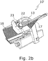
- Fig. 1a is designed as a diagonal cutting machine disc cutting machine 10 'is shown, to which an inventive Grinder 22 (cf. Figure 2a ) can be attached.
- the slicing machine 10' comprises a cutting device 11 in a machine housing 12.
- the cutting device 11 has a rotatably mounted circular blade 13 .
- a cutting edge 14 of the circular blade 13 is covered by a blade protection ring 15 in a first section.
- the slicing machine 10 ′ also includes a stop plate 16 and a slidably arranged carriage 17 , via which a material to be cut (not shown) is fed to the circular blade 13 .
- the stop plate 16 is in the direction of the axis of rotation RA (see Figure 2a ) of the circular blade 13 can be moved.
- the stop plate 16 is in an open position 18 at a distance from the circular blade 13 in the direction of the axis of rotation RA of the circular blade 13.
- the cutting edge 14 of the circular blade 13 is freely accessible.
- a blade cover 19 serves to protect the circular blade 13 along its inner circumference.
- the knife protection ring 15 has an end 20 designed as a projection, which fits into a receptacle 43 of a grinding device 22 (see FIG Figure 4a ) is introduced.
- Fig. 1a also elongated recesses 53a, 53b on the front side of the stop plate 16 facing the carriage 17 for associated bulges 52a, 52b of the grinding device 22 (see Figure 4c ).
- the elongated recesses 53a, 53b receive the bulges 52a, 52b, the recesses do not form a positive fit with the bulges.
- the bulges 52a, 52b may be circular in cross section, as in the embodiment of FIG Figure 4c is shown.
- a disc cutting machine 10" designed as a vertical cutting machine is shown with the carriage 17, the stop plate 16 and the rotatably mounted circular blade 13, on which the grinding device 22 can also be mounted.
- the vertical cutting machine 10" is controlled via a dashboard 21 .
- the grinding device 22 which is in a Figure 2a Installation position 23 shown via a bracket 24 on the stop plate 16 of a slicing machine 10 ', as shown in Fig. 1a shown, in the open position (cf. Fig. 1a ) is mounted.
- the grinding device 22 and the slicing machine 10' together form a slicing system 25.
- the installation position 23 can be recognized in particular by the fact that a housing 26 to protect the operating mechanism (not shown) of the grinding device 22 is pivoted away from the circular blade 13, while this housing 26 is in a working position (see FIG Figure 2c ) is pivoted towards the circular knife 13 .
- a latching mechanism 27 with a latching pin 28 latches the grinder 22 in the installation position 23.
- the latching mechanism 27 also serves to position the grinder 22 in a working position (see FIG Figure 2c ) to lock.
- Pivoting from the working position to the installation position 23 takes place via a pivoting mechanism 30.
- the pivoting mechanism 30 has a guide 31 for guiding the grinding device 22 during pivoting.
- the housing 26 pivots about a pivot pin 32 of the pivot mechanism.
- the pivoting movement of the grinder 22 in the direction of the installation position 23 is stopped by a stop 33 as a buffer.
- the grinder 22 has a handle 34 for moving a grindstone 39 and a whetstone 40 (see Fig Figure 4a ) to the circular knife 13 of the disc cutting machine 10.
- the handle 34 is designed as a wheel 35 which, when rotated, moves the sharpening stone 39 and the sharpening stone 40 to the circular knife 13 or away from the circular knife 13.
- the grinder 22 includes a frame 36 which supports the components described.
- Figure 2b shows for comparison with Fig. 1a the inclined cutting machine 10 'with the carriage 17, the stop plate 16 and the circular blade 13, wherein now the grinder 22 is mounted in the installation position 23 on the stop plate 16.
- the grinding device 22 assumes a working position 38 , which Figure 2c is shown.
- the housing 26 is compared to the installation position 23 (see Figure 2a ) pivoted towards the circular blade 13 and spaced from the stop 33.
- the housing 26 has been pivoted about the rotary pin 32 from the installation position 23 into the working position 38 .
- the carriage 17 cannot be moved over the entire carriage stroke, since otherwise it could collide with the grinder 22 during its movement. In the carriage position shown, the carriage 17 covers a lower part of the cutting edge 14 of the circular blade 13 . A part of the circular blade 13 is also covered by the carriage 17 to protect a user.
- To lock the grinder 22 in the installation position 23 serves a second locking receptacle 29b.
- Figure 3a shows a side view of the grinder 22 in the installation position 23.
- the housing 26 of the grinder 22 rests against the stop 33.
- the latching mechanism 27 with the latching pin 28 latches the grinder 22 in the installation position 23.
- the pivoting mechanism 30 with the guide 31 and the rotary pin 32 is also shown.
- the first latching receptacle 29a is also shown.
- Figure 3b shows a side view of the grinder 22 in the working position 38.
- the housing 26 is pivoted about the rotary pin 32 along the guide 31 and spaced from the stop 33. Also shown is the second latching receptacle 29b.
- the grinder 22 has the grindstone 39 for sharpening the circular blade 13 (see Figure 2a ) and the sharpening stone 40 for deburring the circular knife 13, which in Figure 4a and Figure 4b are shown.
- the whetstone 39 and the The whetstone 40 is moved to the circular knife 13 by means of the wheel 35 (see Figure 2a ) emotional.
- a threaded spindle 41 for clamping the stop plate 16 is located on the holder 24 (see Figure 2b ).
- the frame 36 of the grinder 22 includes cover plates 42a, 42b for covering the circular knife 13.
- the grindstone 39 and the honing stone 40 are arranged in the circumferential direction of the circular knife 13 between such cover plates 42a, 42b of the frame 36.
- the receptacle 43 of the grinding device 22 is designed to hold the end 20 of the knife protection ring 15, which is designed as a projection (see FIG Fig. 1a ) to grip in a form-fitting manner when the stop plate 16 is in the direction of the axis of rotation RA of the circular blade 13 (see Fig. 1b ) has a predetermined distance from the circular blade 13.
- the receptacle 43 does not encompass the end 20 of the knife protection ring 15 when the distance between the stop plate 16 and the knife protection ring 15 in the direction of the axis of rotation RA of the circular knife 13 is smaller than the predetermined distance.
- the receptacle 43 is designed as a recess 44 in the grinding device 22 for inserting the end 20 of the knife protection ring 15 .
- the bracket 24 for attaching the grinder 22 to the stop plate 16 has an in Figure 4c shown, in particular U-shaped, plate holder 45 with a gap 46 for inserting the stop plate 16 into the gap 46 when sliding the grinder 22 onto the stop plate 16.
- the threaded spindle 41 is located at the gap 46 of the plate holder 45.
- Bulges 52a, 52b of the holder 24 engage in associated recesses 53a, 53b on the front of the stop plate 16 (see Fig. 1a ) a.
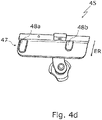
- the holder 24 of the grinding device 22 also has an insertion device 47 for positive insertion into the stop plate 16 .
- the insertion device 47 comprises two lugs 48a, 48b, which fit into associated depressions on a rear side of the stop plate 16 (see figure 5 ) intervene in particular in a form-fitting manner.
- the insertion device 47 with the lugs 48a, 48b is formed on an inner side 49 of the gap 46 of the plate holder 45 on which the stop plate 16 in the assembled state of the Grinder 22 is arranged.
- the lugs 48a, 48b have a U-shape tapering in the direction of insertion ER of the insertion device 47, as shown in FIG Figure 4d is shown in detail.
- the recesses 50a, 50b shown in the stop plate 16 receive the lugs 48a, 48b of the insertion device (see FIG. 3c) in a form-fitting manner.
- the recesses 50a, 50b are formed on a rear surface 51 of the stopper plate 16, which is in the direction of the axis of rotation RA of the circular blade 13 (see Figure 2a ) faces away from the carriage 17 of the slicing machine 10'.
Landscapes
- Engineering & Computer Science (AREA)
- Mechanical Engineering (AREA)
- Life Sciences & Earth Sciences (AREA)
- Forests & Forestry (AREA)
- Food Science & Technology (AREA)
- Finish Polishing, Edge Sharpening, And Grinding By Specific Grinding Devices (AREA)
- Food-Manufacturing Devices (AREA)
Abstract
Description
- Die Erfindung betrifft ein Schleifgerät für eine Scheibenschneidmaschine zum Abschneiden von Scheiben aus insbesondere strangförmigem Schneidegut, vorzugsweise Lebensmittel, wobei das Schleifgerät einen Schleifstein zum Schärfen eines rotierenden Kreismessers der Scheibenschneidmaschine und einen Abziehstein zum Entgraten des Kreismessers umfasst, wobei das Schleifgerät einen Griff aufweist, um den Schleifstein und/oder den Abziehstein zu dem Kreismesser zu bewegen. Die Erfindung betrifft zudem eine Scheibenschneidanlage mit einem solchen Schleifgerät und einer Scheibenschneidmaschine.
- Derartige Schleifgeräte sind aus dem Stand der Technik an sich bekannt.
- Die
US 7 134 937 B1 (= Referenz [1]) betrifft eine Schneidemaschine für Lebensmittelprodukte mit einem drehbaren Schneidemesser. Die Schneidemaschine umfasst einen Schleifapparat und eine zugehörige Messerschutzbaugruppe mit einem Schutzelement, das an einem Messerschutzring so positioniert ist, dass es die Schneidkante des Messers schützt, wenn sich der Schleifapparat in seinem Standby- oder Nicht-Schärfungszustand befindet. Beim Schleifen wird ein Teil des Messerschutzrings geöffnet, um mit dem Schleifapparat die Schneidkante des Messers berühren zu können. - Die
EP 1 922 189 B1 (= Referenz [2]) betrifft eine Nahrungsmittel-Aufschneidevorrichtung mit einem sich drehenden Schneidmesser und einem Schärfmechanismus zum Schärfen des Schneidmessers, wobei der Schärfmechanismus lösbar an einem Abschnitt eines Produkttischs befestigt ist, um sich mit dem Produkttisch zu bewegen und für ein Schärfen des Schneidmessers zu sorgen. Der Schärfmechanismus weist ein sich drehendes Schärfelement und ein Entgratelement auf, wobei das Schärfelement und das Entgratelement unabhängig voneinander montiert sind. Der Schärfmechanismus ist entfernbar in einer Tasche befestigt, die an einem unteren Abschnitt des Nahrungsmittelprodukttischs ausgebildet ist, der dem Messer zugewandt ist. - Um eine prozesssichere Funktion des Schleifgeräts und einen zufriedenstellenden Schleifvorgang sicherzustellen, müssen der Schleifstein und der Abziehstein mit sehr geringen Toleranzen auf das Kreismesser ausgerichtet sein. Deswegen muss auch das Schleifgerät mit geringen Toleranzen mit Bezug zum Kreismesser an der Scheibenschneidemaschine anbringbar sein.
- Da Bauteile wie Messerschutzring und Schlitten diese Toleranzvorgaben nicht erfüllen, müssen sämtliche aus dem Stand der Technik bekannten Schleifgeräte für eine korrekte geometrische Positionierung des Schleifsteins und des Abziehsteins in Bezug auf das Kreismesser der Scheibenschneidmaschine bei der Produktion auf die Scheibenschneidemaschine justiert und ausgerichtet werden. Diese Justage muss bisher bei der Produktion erfolgen, zum Beispiel über Langlöcher. Damit ist ein Schleifgerät stets einer einzigen konkreten, individuellen Schneidemaschine zugeordnet. Insbesondere wenn das Schleifgerät an einem Messerschutzring befestigt werden muss oder den Messerschutzring als Anschlag für die Montageposition benutzt, ist die Zuordnung eines Schleifgeräts zu einer konkreten Scheibenschneidemaschine erforderlich, da der Messeschutzring in der Regel nur innerhalb einer groben geometrischen Toleranz in Bezug auf das Kreismesser an der Scheibenschneidmaschine angeordnet ist. Dabei ist die Zuordnung zu einer ganz bestimmten Scheibenschneidemaschine notwendig, eine Zuordnung eines Schleifgeräts zu einer Scheibenschneidemaschine eines bestimmten Typs ist hier nicht ausreichend.
- Ein Schleifgerät für eine Scheibenschneidemaschine eines bestimmten Typs ist mithin nie ohne erneute Justage für eine andere Scheibenschneidemaschine unmittelbar einsetzbar, selbst wenn die andere Scheibenschneidemaschine exakt vom selben Typ ist wie die erste.
- Demgegenüber liegt der vorliegenden Erfindung die -im Detail betrachtet relativ anspruchsvolle- Aufgabe zugrunde, ein Schleifgerät zum Schleifen eines Kreismessers bereitzustellen, das durch die Art und Weise seiner Positionierung an einer Scheibenschneidmaschine auf einfache Weise für viele Scheibenschneidmaschinen gleichen Typs ohne weitere aufwändige Justage vor dem eigentlichen Schleifvorgang verwendbar ist. Es ist ferner Aufgabe der Erfindung, eine Scheibenschneidanlage mit einem solchen Schleifgerät und einer Scheibenschneidmaschine bereitzustellen.
- Diese Aufgabe wird durch die vorliegende Erfindung auf ebenso überraschend einfache wie wirkungsvolle Weise dadurch gelöst, dass ein generisches Schleifgerät der eingangs definierten Art eine Halterung zur Befestigung an einer Anschlagplatte der Scheibenschneidmaschine mit einer Einschubeinrichtung zum formschlüssigen Einschieben in die Anschlagplatte aufweist, wobei die Halterung eine U-förmige Plattenaufnahme mit einem Spalt zum Einführen der Anschlagplatte in den Spalt beim Aufschieben des Schleifgeräts auf die Anschlagplatte aufweist, und dass die Einschubeinrichtung mindestens eine Nase, vorzugsweise zwei Nasen, zum Eingreifen in eine zugehörige Vertiefung der Anschlagplatte aufweist oder dass die Anschlagplatte mindestens eine Nase, vorzugsweise zwei Nasen, zum Eingreifen in eine zugehörige Vertiefung der Einschubeinrichtung aufweist.
- Damit wird die -bisher stets vorhandene und gravierende- Einschränkung der Verwendung von einem Schleifgerät nur auf einer einzigen konkreten, dem Schleifgerät zugeordneten Scheibenschneidmaschine beseitigt.
- Die Nasen werden durch Einschieben in die Vertiefungen fixiert, wobei die Vertiefungen insbesondere formschlüssige Aufnahmen für die Nasen bilden. Nach dem Einschieben in die Vertiefungen verhindern die Nasen ein Verschieben des Schleifgeräts entlang der Anschlagplatte. Über die Nasen und die zugehörigen Vertiefungen wird der Schleifapparat an der Anschlagplatte ausgerichtet.
- Die Anschlagplatte ist gegenüber dem Kreismesser bei der Produktion der Scheibenschneidmaschine in der Regel mit relativ hoher Genauigkeit ausgerichtet, wobei diese Positionierung für viele Scheibenschneidmaschinen gleich ist, insbesondere für solche gleichen Typs. Dabei ist die Anschlagplatte in der Regel mit Langlöchern am Maschinengehäuse befestigt und damit auf das Kreismesser justiert. Durch die genaue Positionierung der Anschlagplatte weist die Position der Anschlagplatte relativ zum Kreismesser keine oder nur relativ geringe Toleranzen auf und ist insbesondere bei vielen Scheibenschneidmaschinen gleich, selbst wenn der Typ leicht variiert. Durch eine exakte Positionierung des Schleifgeräts an der Anschlagplatte, die durch die Nasen und die zugehörigen Vertiefungen bestimmt ist, kann das Schleifgerät auf jeder dieser Scheibenschneid-maschinen mit ausreichend kleinen Toleranzen angebracht werden, ohne dass eine exakte neue Justage erforderlich wird. Dadurch kann ein einziges Schleifgerät für verschiedene Scheibenschneidmaschinen aufgrund seiner genauen Positionierung relativ zum Schneidmesser sofort nach seiner Montage unmittelbar zum Schleifen des Messers verwendet werden. Mit anderen Worten hat dies den günstigen Effekt, dass eine Justage während der Produktion eines Schleifgeräts für eine erste Scheibenschneidemaschine eines bestimmten Typs gleichzeitig auch eine Justage des Schleifgeräts für eine zweite Scheibenschneidemaschine des gleichen Typs beinhaltet. Das Schleifgerät ist somit für mehrere Scheibenschneidemaschinen des gleichen oder ähnlichen Typs nutzbar, ohne es immer wieder neu justieren zu müssen.
- Insbesondere bei Ausführungsformen der Scheibenschneidmaschine, deren Anschlagplatte in Bezug auf das Kreismesser in einer Richtung der Drehachse des Kreismessers verfahrbar ist, kann das Schleifgerät mittels der Halterung an der Anschlagplatte befestigt oder von der Anschlagplatte entfernt werden, wenn der Abstand zwischen der Anschlagplatte und dem Messerschutzring in Richtung der Drehachse des Kreismessers kleiner als ein vorbestimmter Abstand ist, das heißt insbesondere, wenn sich die Anschlagplatte in einer geschlossenen Stellung befindet. Anschließend kann das Schleifgerät mit hoher Präzision bei verschieden Scheibenschneidmaschinen durch Verfahren der Anschlagplatte relativ zu dem Kreismesser ausgerichtet werden. Die Anschlagplatte geht dabei durch das Verfahren in eine offene Stellung über.
- Die Scheibenschneidmaschine kann insbesondere als Vertikalschneidemaschine oder Schrägschneidemaschine ausgebildet sein.
- Der Schleifstein des Schleifgeräts berührt die Schneidkante in einem ersten Schritt von einer Seite und schärft damit die Schneidkante. Der Abziehstein des Schleifgeräts berührt die Schneidkante in einem zweiten Schritt von der anderen Seite und zieht das Messer ab, wobei er z B. einen Grat entfernt.
- In den Rahmen der vorliegenden Erfindung fällt auch eine Scheibenschneidanlage mit einer Scheibenschneidmaschine zum Abschneiden von Scheiben aus insbesondere strangförmigem Schneidegut, vorzugsweise Lebensmittel, mit einem Maschinengehäuse, das einen Antriebsmotor und ein vom Antriebsmotor angetriebenes, rotierendes Kreismesser haltert, wobei eine Schneidkante des Kreismessers in einem ersten Teilabschnitt von einem Messerschutzring überdeckt ist, wobei die Scheibenschneidmaschine eine Anschlagplatte sowie einen verschiebbar angeordneten Schlitten umfasst, über den das Schneidegut dem Kreismesser zugeführt wird, wobei die Anschlagplatte in Richtung der Drehachse des Kreismessers verfahrbar ist, wobei die Scheibenschneidanlage ein Schleifgerät zum Schleifen des Kreismessers aufweist, wobei das Schleifgerät einen Schleifstein zum Schärfen des Kreismessers und einen Abziehstein zum Entgraten des Kreismessers aufweist, wobei das Schleifgerät einen Griff aufweist, um den Schleifstein und/oder den Abziehstein zu dem Kreismesser zu bewegen.
- Diese Scheibenschneidanlage zeichnet sich erfindungsgemäß dadurch aus, dass das Schleifgerät eine Halterung zur Befestigung an der Anschlagplatte mit einer Einschubeinrichtung zum formschlüssigen Einschieben in die Anschlagplatte aufweist, wobei die Halterung eine, insbesondere U-förmige, Plattenaufnahme mit einem Spalt zum Einführen der Anschlagplatte in den Spalt beim Aufschieben des Schleifgeräts auf die Anschlagplatte aufweist, und dass die Einschubeinrichtung mindestens eine Nase, vorzugsweise zwei Nasen, zum Eingreifen in eine zugehörige Vertiefung der Anschlagplatte aufweist oder dass die Anschlagplatte mindestens eine Nase, vorzugsweise zwei Nasen, zum Eingreifen in eine zugehörige Vertiefung der Einschubeinrichtung aufweist.
- Die Schleifgeräte derartiger Scheibenschneidanlagen lassen sich durch die Art ihrer Positionierung für eine Vielzahl von Scheibenschneidgeräten, insbesondere gleichen Typs, verwenden. Die Anschlagplatten sind in der Regel mit einer hohen Genauigkeit in Bezug auf das Kreismesser positioniert, wobei diese Positionierung insbesondere für viele Scheibenschneidmaschinen gleich ist. Durch die Befestigung an der Anschlagplatte ist daher auch das Schleifgerät, das an der Anschlagplatte befestigt ist, mit wenig oder keiner Toleranz zu dem Kreismesser angeordnet. Insbesondere ist auf diese Weise die Positionierung und die Ausrichtung des Schleifgeräts relativ zu dem Kreismesser bei vielen Scheibenschneidmaschinen gleich. Dadurch kann ein Schleifgerät mit genauer Positionierung für verschiedene Scheibenschneidmaschinen verwendet werden.
- Eine Klasse von vorteilhaften Ausführungsformen des erfindungsgemäßen Schleifgeräts zeichnet sich dadurch aus, dass die mindestens eine Nase insbesondere dazu ausgebildet ist, in eine Vertiefung auf einer Rückseite der Anschlagplatte einzugreifen, und wobei die Rückseite der Anschlagplatte in der Richtung der Drehachse des Kreismessers von einem Schlitten der Scheibenschneidmaschine abgewandt ist. Das Schleifgerät liegt bei dieser Ausführungsform insbesondere an der dem Schlitten zugewandten Vorderseite der Anschlagplatte an, um das Kreismesser zu schleifen und ist andererseits über die Nase an der Rückseite der Anschlagplatte befestigt. Die Halterung umgreift dabei eine im montierten Zustand der Anschlagplatte obere Kante der Anschlagplatte. Durch die Anordnung an beiden Seiten der Anschlagplatte wird das Schleifgerät besonders stabil in seiner Position an der Anschlagplatte gehalten.
- Vorteilhaft sind auch Ausführungsformen des erfindungsgemäßen Schleifgeräts, bei denen die Halterung zur Befestigung des Schleifgeräts an einer Anschlagplatte der Scheibenschneidmaschine eine Gewindespindel zum Einklemmen der Anschlagplatte aufweist. Durch die Gewindespindel lässt sich die Anschlagplatte stabil, aber manuell lösbar mit dem Schleifgerät verbinden. Die Gewindespindel befindet sich insbesondere an einer Seite des Spaltes der U-förmigen Plattenaufnahme, um die Anschlagplatte gegen die gegenüberliegende Seite der U-förmigen Plattenaufnahme zu drücken und dadurch das Schleifgerät an der Anschlagplatte festzuklemmen.
- Weiterhin vorteilhaft sind Ausführungsformen des Schleifgeräts, die sich dadurch auszeichnen, dass die Einschubeinrichtung an der Innenseite des Spalts der Plattenaufnahme ausgebildet ist. An der Innenseite des Spalts wird insbesondere die Anschlagplatte beim Einschieben in den Spalt entlanggeführt. Die Einschubeinrichtung ist insbesondere in Form der vorgenannten Nasen an der Innenseite des Spalts ausgebildet. Während die Plattenaufnahme die Anschlagplatte bei dem Einschieben umgreift, um ein Verschieben des Schleifgeräts in der Richtung der Drehachse des Kreismessers zu verhindern, unterbindet die Einschubeinrichtung an der Innenseite des Spalts ein Verschieben des Schleifgeräts entlang der Anschlagplatte bereits während des Einschiebens der Anschlagplatte.
- Bei weiteren Ausgestaltungen des Schleifgeräts weist die Einschubeinrichtung in einer Richtung des Einschubs eine sich verjüngende Form, insbesondere eine U-Form, auf. Dadurch zentriert sich die Einschubeinrichtung beim Einschieben in die Aufnahme der Anschlagplatte, was das Einschieben erleichtert.
- Eine weitere Ausführungsform des Schleifgeräts ist dadurch gekennzeichnet, dass eine Aufnahme des Schleifgeräts zum formschlüssigen Umgreifen eines Endes eines Messerschutzrings der Scheibenschneidmaschine vorhanden ist, wobei die Aufnahme dazu ausgebildet ist, das Ende des Messerschutzrings zu umgreifen, wenn die Anschlagplatte in Richtung einer Drehachse des Kreismessers mindestens einen vorbestimmten Abstand von dem Kreismesser aufweist, und das Ende des Messerschutzrings nicht zu umgreifen, wenn der Abstand zwischen der Anschlagplatte und dem Messerschutzring in Richtung der Drehachse des Kreismessers kleiner als der vorbestimmte Abstand ist.
- Damit wird eine Verletzungsgefahr beim Montieren und Demontieren des Schleifgeräts sowie eine mangelnde Hygiene bei dem Gebrauch des Schleifgeräts vermieden. Wenn der Abstand zwischen der Anschlagplatte und dem Messerschutzring in Richtung der Drehachse des Kreismessers kleiner als der vorbestimmte Abstand ist, das heißt insbesondere, wenn sich die Anschlagplatte in einer geschlossenen Stellung befindet, umgreift die Aufnahme das Ende des Messerschutzrings nicht.
- Das Schleifgerät kann dann mittels der Halterung an der Anschlagplatte befestigt oder von der Anschlagplatte entfernt werden. Das von der Anschlagplatte und dem Messerschutzring überdeckte Kreismesser kann in der geschlossenen Stellung der Anschlagplatte nicht berührt werden, sodass keine Verletzungsgefahr besteht. Somit kann das Schleifgerät vorteilhaft schon an der Anschlagplatte angebracht werden, wenn diese noch in der geschlossenen Stellung und die Scheibenschneidmaschine noch verletzungssicher ist. Um die Sicherheit des Benutzers während des Schleifens zu gewährleisten, wird mit anderen Worten das Schleifgerät schon an die Scheibenschneidmaschine montiert, wenn die Scheibenschneidmaschine sich in diesem sicheren Zustand befindet, das heißt wenn das Schneidmesser komplett abgedeckt ist. Die Anschlagplatte deckt in der geschlossenen Stellung insbesondere einen Abschnitt der Schneidkante des Schneidmessers ab, der nicht durch den Messerschutzring überdeckt wird.
- Nach der Montage des Schleifgeräts bei geschlossener Stellung der Anschlagplatte wird die Anschlagplatte zum Schleifen des Kreismessers aus der geschlossenen Stellung verschoben, sodass die Anschlagplatte in Richtung einer Drehachse des Kreismessers mindestens einen vorbestimmten Abstand von dem Kreismesser aufweist, das heißt, dass sich die Anschlagplatte in einer offenen Stellung befindet. Das Schleifgerät wird dadurch an die nunmehr zugängliche Schneidkante des Kreismessers herangeführt. Bei der Verschiebung der Anschlagplatte wird das Ende des Messerschutzrings in der Richtung der Drehachse des Kreismessers in die Aufnahme eingeführt, die in der offenen Stellung der Anschlagplatte das Ende des Messerschutzrings umgreift. Die Aufnahme weist dabei insbesondere eine Führung zum Einführen des Messerschutzrings auf.
- Das Schleifgerät wirkt bei offener Anschlagplatte mit dem Messerschutzring zusammen. Gemeinsam mit der in die Anschlagplatte eingeschobenen Einschubeinrichtung des Schleifgeräts verhindert die Aufnahme bei der offenen Stellung der Anschlagplatte, dass das Schleifgerät während des Schleifens des Kreismessers abgenommen werden kann und dadurch die Gefahr einer Schnittverletzung des Benutzers entsteht. Insbesondere kann bei geöffneter Anschlagplatte das Schleifgerät weder in einer Richtung entlang der Anschlagplatte noch senkrecht zu dieser Richtung abgenommen werden. Mittels der Aufnahme des Schleifgeräts für den Messerschutzring fixiert der Messerschutzring das Schleifgerät bei geöffneter Anschlagplatte, nicht jedoch bei geschlossener Anschlagplatte.
- Der Messerschutzring ist vorzugsweise C-förmig ausgestaltet, um das Kreismesser abzudecken.
- Eine Weiterentwicklung der vorgenannten Ausführungsform des erfindungsgemäßen Schleifgeräts zeichnet sich dadurch aus, dass die Aufnahme als Aussparung zum Einführen des Endes des Messerschutzrings ausgebildet ist. Die Aufnahme umgreift das Ende des Messerschutzrings und sorgt so für einen sicheren Halt des Schleifgeräts an dem Ende des Messerschutzrings. Als Aussparung ist die Aufnahme besonders materialsparend ausgebildet.
- Bei einer vorteilhaften Ausgestaltung weist das Schleifgerät einen Rahmen zum Überdecken zumindest eines Teilabschnitts einer Schneidkante des Kreismessers und zum Verschwenken des Schleifgeräts von einer Installationsstellung in eine Arbeitsstellung auf. Der Rahmen vermindert das Risiko einer Schnittverletzung eines Benutzers an dem Kreismesser. Das Montieren des Schleifgeräts an der Scheibenschneidmaschine erfolgt insbesondere in der Installationsstellung, während die Arbeitsstellung des Schleifgeräts das Schleifen des Kreismessers durch das Schleifgerät bezweckt.
- Bei einer Weiterentwicklung der vorgenannten Ausgestaltung umfasst der Rahmen des Schleifgeräts Abdeckplatten zur Überdeckung der Schneidkante des Kreismessers, wobei der Schleifstein und der Abziehstein insbesondere zwischen den Abdeckplatten angeordnet sind. Die Abdeckplatten schützen durch ihre Ausdehnung während des Verfahrens der Anschlagplatte einen Benutzer vor Schnittverletzungen durch die Schneidkante des Kreismessers. Die Abdeckplatten, der Schleifstein und der Abziehstein sind insbesondere in Umfangsrichtung des Kreismessers angeordnet, wobei der Schleifstein und der Abziehstein zwischen den Abdeckplatten positioniert sind.
- Weitere Ausführungsformen des erfindungsgemäßen Schleifgeräts sind durch einen Rastmechanismus zum Verrasten des Schleifgeräts in der Arbeitsstellung und/oder in der Installationsstellung gekennzeichnet. Hierdurch wird das Schleifgerät stabil, aber manuell lösbar in der jeweiligen Stellung gehalten. Der Rastmechanismus wird zum Beispiel durch einen Rast-Pin und elastische Elemente an dem Schleifgerät ausgebildet.
- Eine bevorzugte Variante des erfindungsgemäßen Schleifgeräts zeichnet sich durch einen Schwenkmechanismus zum Verschwenken des Schleifgeräts von der Arbeitsstellung in die Installationsstellung aus. Der Schwenkmechanismus weist vorzugsweise eine Führungsnut und/oder eine Führungsschiene zum Führen des Schleifgeräts beim Verschwenken auf und/oder einen Dreh-Pin, um den das Schleifgerät ganz oder teilweise verschwenkbar ist. Besonders bevorzugt greift der vorgenannte Rast-Pin in die Führungsnut ein und/oder wird an der Führungsschiene entlanggeführt, wodurch das Schleifgerät zwischen den Rastpositionen von der Arbeitsstellung in die Installationsstellung verschwenkt werden kann.
- Eine Weiterentwicklung der vorgenannten Variante ist durch einen Anschlag für den Schwenkmechanismus gekennzeichnet. Der Anschlag bremst die Verschwenkung auf stabile Weise ab und schützt als Puffer das Schleifgerät vor mechanischen Schäden durch das Verschwenken.
- Eine weitere bevorzugte Ausführungsform des erfindungsgemäßen Schleifgeräts ist dadurch gekennzeichnet, dass der Griff zum Bewegen des Schleifsteins und/oder des Abziehsteins zu dem Kreismesser der Scheibenschneidmaschine als ein Rad des Rahmens des Schleifgeräts ausgebildet ist, wobei das Rad dazu ausgebildet ist, beim Drehen den Schleifstein und/oder den Abziehstein zu dem Kreismesser zu bewegen, sodass sie am Kreismesser anordenbar sind, und/oder vom Kreismesser wegbewegt werden kann. Durch das Rad und einen damit verbundenen Drehmechanismus lässt sich die Verstellung des Schleifsteins und/oder des Abziehsteins raumsparend bewirken.
- Eine vorteilhafte Ausgestaltung der weiter oben beschriebenen erfindungsgemäßen Scheibenschneidanlage ist dadurch gekennzeichnet, dass die Vertiefung bevorzugt auf einer Rückseite der Anschlagplatte ausgebildet ist, die in der Richtung der Drehachse des Kreismessers von einem Schlitten der Scheibenschneidmaschine abgewandt ist. Bei dieser Ausführungsform liegt das Schleifgerät insbesondere an beiden Seite der Anschlagplatte an und wird dadurch besonders stabil in seiner Position an der Anschlagplatte gehalten.
- Weitere Vorteile der Erfindung ergeben sich aus der Beschreibung und der Zeichnung. Ebenso können die vorstehend genannten und die noch weiter ausgeführten Merkmale erfindungsgemäß jeweils einzeln für sich oder zu mehreren in beliebigen Kombinationen Verwendung finden. Die gezeigten und beschriebenen Ausführungsformen sind nicht als abschließende Aufzählung zu verstehen, sondern haben vielmehr beispielhaften Charakter für die Schilderung der Erfindung.
- Die Erfindung ist in der Zeichnung dargestellt und wird anhand von Ausführungsbeispielen näher erläutert.
- Es zeigen:
- Fig. 1a
- eine räumliche Ansicht einer als Schrägschneidemaschine ausgebildeten Scheibenschneidmaschine;
- Fig. 1b
- eine räumliche Ansicht einer als Vertikalschneidemaschine ausgebildeten Scheibenschneidmaschine;
- Fig. 2a
- eine Seitenansicht einer Scheibenschneidanlage umfassend eine Scheibenschneidmaschine und ein Schleifgerät in einer Installationsstellung;
- Fig. 2b
- eine Ansicht der Scheibenschneidanlage nach
Fig. 2a von schräg oben; - Fig. 2c
- eine Seitenansicht eines Teils der Scheibenschneidanlage nach
Fig. 2a mit dem Schleifgerät in einer Arbeitsstellung; - Fig. 3a
- eine Seitenansicht einer Ausführungsform des erfindungsgemäßen Schleifgeräts in der Installationsstellung;
- Fig. 3b
- eine Seitenansicht des Schleifgeräts nach
Fig. 3a in der Arbeitsstellung; - Fig. 4a
- eine Innenansicht des Schleifgeräts von einer Seite, die im montierten Zustand des Schleifgeräts einem Kreismesser der Scheibenschneidmaschine zugewandt ist;
- Fig. 4b
- eine Innenansicht des Schleifgeräts von einer Seite, auf der sich eine Halterung des Schleifgeräts befindet;
- Fig. 4c
- eine Innenansicht des Schleifgeräts von einer im montierten Zustand des Schleifgeräts unten befindlichen Seite;
- Fig. 4d
- eine Ansicht einer Halterung des Schleifgeräts mit einer Einschubeinrichtung;
- Fig. 5
- eine schematische räumliche Ansicht der Rückseite einer Anschlagplatte.
- Die vorliegende Erfindung befasst sich mit einem Schleifgerät für eine Scheibenschneidmaschine zum Abschneiden von Scheiben aus insbesondere strangförmigem Schneidegut, vorzugsweise Lebensmittel.
- Die
Figuren 1a und1b zeigen isometrische Ansichten einer als Schrägschneidemaschine beziehungsweise einer als Vertikalschneidemaschine ausgestalteten Scheibenschneidemaschine. DieFiguren 2a bis 2c zeigen ein erfindungsgemäßes Schleifgerät in einer Installationsstellung und einer Arbeitsstellung an der Schrägschneidemaschine. DieFiguren 3a bis 4d zeigen verschiedene Ansichten des Schleifgeräts. DieFig. 5 zeigt eine Anschlagplatte der Scheibenschneidmaschine mit Vertiefungen zur Aufnahme von Nasen des Schleifgeräts. - In
Fig. 1a ist eine als Schrägschneidemaschine ausgebildete Scheibenschneidmaschine 10' gezeigt, an welche ein erfindungsgemäßes Schleifgerät 22 (vgl.Fig. 2a ) angebracht werden kann. Die Scheibenschneidmaschine 10' umfasst eine Schneideeinrichtung 11 in einem Maschinengehäuse 12. Die Schneideeinrichtung 11 weist ein rotierbar gelagertes Kreismesser 13 auf. Dabei ist eine Schneidkante 14 des Kreismessers 13 in einem ersten Teilabschnitt von einem Messerschutzring 15 überdeckt. - Weiter umfasst die Scheibenschneidmaschine 10' eine Anschlagplatte 16 sowie einen verschiebbar angeordneten Schlitten 17, über den ein Schneidegut (nicht gezeigt) dem Kreismesser 13 zugeführt wird. Hierbei ist die Anschlagplatte 16 in Richtung der Drehachse RA (siehe
Fig. 2a ) des Kreismessers 13 verfahrbar. InFig. 1a befindet sich die Anschlagplatte 16 in einer offenen Stellung 18 mit einem Abstand von dem Kreismesser 13 in Richtung der Drehachse RA des Kreismessers 13. Die Schneidkante 14 des Kreismessers 13 ist frei zugänglich. Eine Messerabdeckung 19 dient dem Schutz vor dem Kreismesser 13 an seinem Innenumfang entlang. Der Messerschutzring 15 weist ein als Vorsprung ausgebildetes Ende 20 auf, welches in eine Aufnahme 43 eines Schleifgeräts 22 (sieheFig. 4a ) eingeführt wird. Gezeigt sind inFig. 1a auch längliche Ausnehmungen 53a, 53b auf der dem Schlitten 17 zugewandten Vorderseite der Anschlagplatte 16 für zugehörige Ausbuchtungen 52a, 52b des Schleifgeräts 22 (sieheFig. 4c ). Wenn die länglichen Ausnehmungen 53a, 53b die Ausbuchtungen 52a, 52b aufnehmen, bilden die Ausnehmungen jeweils keinen Formschluss mit den Ausbuchtungen. Insbesondere können die Ausbuchtungen 52a, 52b im Querschnitt kreisförmig ausgebildet sein, wie in der Ausführungsform vonFig. 4c gezeigt ist. - Als Alternative zu einer Schrägschneidemaschine 10' gemäß
Fig. 1a ist inFig. 1b eine als Vertikalschneidemaschine ausgebildete Scheibenschneidmaschine 10" mit dem Schlitten 17, der Anschlagplatte 16 und dem rotierend gelagerten Kreismesser 13 dargestellt, an der das Schleifgerät 22 ebenfalls montiert werden kann. Die Vertikalschneidemaschine 10" wird über ein Armaturenbrett 21 gesteuert. - Zum Schleifen des um die Drehachse RA drehbar gelagerten Kreismessers 13 wird das Schleifgerät 22 verwendet, das in einer in
Fig. 2a gezeigten Installationsstellung 23 über eine Halterung 24 an der Anschlagplatte 16 einer Scheibenschneidmaschine 10', wie sie inFig. 1a dargestellt ist, in der offenen Stellung (vgl.Fig. 1a ) montiert wird. Das Schleifgerät 22 und die Scheibenschneidmaschine 10' bilden zusammen eine Scheibenschneidanlage 25. - Die Installationsstellung 23 ist insbesondere daran zu erkennen, dass ein Gehäuse 26 zum Schutz des Bedienmechanismus (nicht gezeigt) des Schleifgeräts 22 von dem Kreismesser 13 weggeschwenkt ist, während dieses Gehäuse 26 in einer Arbeitsstellung (siehe
Fig. 2c ) zu dem Kreismesser 13 hin geschwenkt ist. Ein Rastmechanismus 27 mit einem Rast-Pin 28 verrastet das Schleifgerät 22 in der Installationsstellung 23. Der Rastmechanismus 27 dient auch dazu, durch eine erste Rastaufnahme 29a das Schleifgerät 22 in einer Arbeitsstellung (sieheFig. 2c ) zu verrasten. - Das Verschwenken von der Arbeitsstellung in die Installationsstellung 23 erfolgt über einen Schwenkmechanismus 30. Der Schwenkmechanismus 30 weist eine Führung 31 zum Führen des Schleifgeräts 22 beim Verschwenken auf. Das Gehäuse 26 wird um einen Dreh-Pin 32 des Schwenkmechanismus verschwenkt. Die Schwenkbewegung des Schleifgeräts 22 in Richtung der Installationsstellung 23 wird durch einen Anschlag 33 als Puffer gestoppt.
- Das Schleifgerät 22 verfügt über einen Griff 34 zum Bewegen eines Schleifsteins 39 und eines Abziehsteins 40 (siehe
Fig. 4a ) zu dem Kreismesser 13 der Scheibenschneidmaschine 10. Der Griff 34 ist als ein Rad 35 ausgebildet, welches beim Drehen den Schleifstein 39 und den Abziehstein 40 zu dem Kreismesser 13 bewegt bzw. vom Kreismesser 13 wegbewegt. Das Schleifgerät 22 umfasst einen Rahmen 36, der die beschriebenen Komponenten trägt. -
Fig. 2b zeigt zum Vergleich mitFig. 1a die Schrägschneidemaschine 10' mit dem Schlitten 17, der Anschlagplatte 16 und dem Kreismesser 13, wobei nunmehr das Schleifgerät 22 in der Installationsstellung 23 an der Anschlagplatte 16 montiert ist. - Zum Schleifen des Kreismessers 13 nimmt das Schleifgerät 22 eine Arbeitsstellung 38 ein, die in
Fig. 2c gezeigt ist. Das Gehäuse 26 ist im Vergleich zu der Installationsstellung 23 (sieheFig. 2a ) zu dem Kreismesser 13 hingeschwenkt und von dem Anschlag 33 beabstandet. Dabei ist das Gehäuse 26 um den Dreh-Pin 32 von der Installationsstellung 23 in die Arbeitsstellung 38 geschwenkt worden. Der Schlitten 17 kann nicht über den gesamten Schlittenhub bewegt werden, da er sonst bei seiner Bewegung mit dem Schleifgerät 22 kollidieren könnte. In der dargestellten Schlittenposition deckt der Schlitten 17 einen unteren Teil der Schneidkante 14 des Kreismessers 13 ab. Zum Schutz eines Nutzers wird ein Teil des Kreismessers 13 zudem durch den Schlitten 17 abgedeckt. Zum Verrasten des Schleifgeräts 22 in der Installationsstellung 23 (sieheFig. 2a ) dient eine zweite Rastaufnahme 29b. -
Fig. 3a zeigt eine Seitenansicht des Schleifgeräts 22 in der Installationsstellung 23. Das Gehäuse 26 des Schleifgeräts 22 liegt an dem Anschlag 33 an. Der Rastmechanismus 27 mit dem Rast-Pin 28 verrastet das Schleifgerät 22 in der Installationsstellung 23. Gezeigt ist auch der Schwenkmechanismus 30 mit der Führung 31 und dem Dreh-Pin 32. Gezeigt ist ferner die erste Rastaufnahme 29a. -
Fig. 3b zeigt eine Seitenansicht des Schleifgeräts 22 in der Arbeitsstellung 38. Das Gehäuse 26 ist von um den Dreh-Pin 32 entlang der Führung 31 verschwenkt und von dem Anschlag 33 beabstandet. Dargestellt ist ferner die zweite Rastaufnahme 29b. - Das Schleifgerät 22 weist den Schleifstein 39 zum Schärfen des Kreismessers 13 (siehe
Fig. 2a ) und den Abziehstein 40 zum Entgraten des Kreismessers 13 auf, welche inFig. 4a undFig. 4b dargestellt sind. Der Schleifstein 39 und der Abziehstein 40 werden mittels des Rades 35 zu dem Kreismesser 13 (sieheFig. 2a ) bewegt. An der Halterung 24 befindet sich eine Gewindespindel 41 zum Einklemmen der Anschlagplatte 16 (sieheFig. 2b ). Der Rahmen 36 des Schleifgeräts 22 umfasst Abdeckplatten 42a, 42b zur Überdeckung des Kreismessers 13. Der Schleifstein 39 und der Abziehstein 40 sind in Umfangsrichtung des Kreismessers 13 zwischen solchen Abdeckplatten 42a, 42b des Rahmens 36 angeordnet. - Die Aufnahme 43 des Schleifgeräts 22 ist dazu ausgebildet, das als Vorsprung ausgebildete Ende 20 des Messerschutzrings 15 (siehe
Fig. 1a ) formschlüssig zu umgreifen, wenn die Anschlagplatte 16 in Richtung der Drehachse RA des Kreismessers 13 (sieheFig. 1b ) einen vorbestimmten Abstand von dem Kreismesser 13 aufweist. Die Aufnahme 43 umgreift das Ende 20 des Messerschutzrings 15 nicht, wenn der Abstand zwischen der Anschlagplatte 16 und dem Messerschutzring 15 in Richtung der Drehachse RA des Kreismessers 13 kleiner als der vorbestimmte Abstand ist. Die Aufnahme 43 ist als Aussparung 44 des Schleifgeräts 22 zum Einführen des Endes 20 des Messerschutzrings 15 ausgebildet. - Die Halterung 24 zum Befestigen des Schleifgeräts 22 an der Anschlagplatte 16 (siehe
Fig. 2a ) weist eine inFig. 4c gezeigte, insbesondere U-förmige, Plattenaufnahme 45 mit einem Spalt 46 zum Einführen der Anschlagplatte 16 in den Spalt 46 beim Aufschieben des Schleifgeräts 22 auf die Anschlagplatte 16 auf. Die Gewindespindel 41 befindet sich an dem Spalt 46 der Plattenaufnahme 45. Ausbuchtungen 52a, 52b der Halterung 24 greifen in zugehörige Ausnehmungen 53a, 53b auf der Vorderseite der Anschlagplatte 16 (sieheFig. 1a ) ein. Die Halterung 24 des Schleifgeräts 22 weist auch eine Einschubeinrichtung 47 zum formschlüssigen Einschieben in die Anschlagplatte 16 auf. Die Einschubeinrichtung 47 umfasst zwei Nasen 48a, 48b, die in zugehörige Vertiefungen auf einer Rückseite der Anschlagplatte 16 (sieheFig. 5 ) insbesondere formschlüssig eingreifen. Die Einschubeinrichtung 47 mit den Nasen 48a, 48b ist an einer Innenseite 49 des Spalts 46 der Plattenaufnahme 45 ausgebildet, an der die Anschlagplatte 16 im montierten Zustand des Schleifgeräts 22 angeordnet ist. Die Nasen 48a, 48b weisen in der Richtung des Einschubs ER der Einschubeinrichtung 47 eine sich verjüngende U-Form auf, wie inFig. 4d detailliert gezeigt ist. - Zwei in
Fig. 5 dargestellte Vertiefungen 50a, 50b der Anschlagplatte 16 nehmen die Nasen 48a, 48b der Einschubeinrichtung (siehe Fig. 3c) formschlüssig auf. Die Vertiefungen 50a, 50b sind auf einer Rückseite 51 der Anschlagplatte 16 ausgebildet, die in der Richtung der Drehachse RA des Kreismessers 13 (sieheFig. 2a ) von dem Schlitten 17 der Scheibenschneidmaschine 10' abgewandt ist. -
- 10'
- Schrägschneidmaschine
- 10"
- Vertikaleschneidmaschine
- 11
- Schneideeinrichtung
- 12
- Maschinengehäuse
- 13
- Kreismesser
- 14
- Schneidkante
- 15
- Messerschutzring
- 16
- Anschlagplatte
- 17
- Schlitten
- 18
- offene Stellung der Anschlagplatte
- 19
- Messerabdeckung
- 20
- Ende des Messerschutzrings
- 21
- Armaturenbrett
- 22
- Schleifgerät
- 23
- Installationsstellung
- 24
- Halterung
- 25
- Scheibenschneidanlage
- 26
- Gehäuse
- 27
- Rastmechanismus
- 28
- Rast-Pin
- 29a,b
- Rastaufnahmen
- 30
- Schwenkmechanismus
- 31
- Führung
- 32
- Dreh-Pin
- 33
- Anschlag
- 34
- Griff
- 35
- Rad
- 36
- Rahmen
- 38
- Arbeitsstellung
- 39
- Schleifstein
- 40
- Abziehstein
- 41
- Gewindespindel
- 42a,b
- Abdeckplatten
- 43
- Aufnahme
- 44
- Aussparung
- 45
- Plattenaufnahme
- 46
- Spalt
- 47
- Einschubeinrichtung
- 48a, 48b
- Nasen
- 49
- Innenseite des Spalts
- 50a,b
- Vertiefungen
- 51
- Rückseite der Anschlagplatte
- 52a,b
- Ausbuchtungen
- 53a,b
- Aussparungen
- RA
- Drehachse
- ER
- Einschubrichtung
- Für die Beurteilung der Patentfähigkeit in Betracht gezogene Publikationen:
- [1]
US 7 134 937 B1 - [2]
EP 1 922 189 B1
Claims (15)
- Schleifgerät (22) für eine Scheibenschneidmaschine (10', 10") zum Abschneiden von Scheiben aus insbesondere strangförmigem Schneidegut, vorzugsweise Lebensmittel, wobei das Schleifgerät (22) einen Schleifstein (39) zum Schärfen eines rotierenden Kreismessers (13) der Scheibenschneidmaschine (10', 10") und einen Abziehstein (40) zum Entgraten des Kreismessers (13) umfasst, wobei das Schleifgerät (22) einen Griff (34) aufweist, um den Schleifstein (39) und/oder den Abziehstein (40) zu dem Kreismesser (13) zu bewegen,
dadurch gekennzeichnet,
dass das Schleifgerät (22) eine Halterung (24) zur Befestigung an einer Anschlagplatte (16) der Scheibenschneidmaschine (10',10") mit einer Einschubeinrichtung (47) zum formschlüssigen Einschieben in die Anschlagplatte (16) aufweist, wobei die Halterung (24) eine U-förmige Plattenaufnahme (45) mit einem Spalt (46) zum Einführen der Anschlagplatte (16) in den Spalt (46) beim Aufschieben des Schleifgeräts (22) auf die Anschlagplatte (16) aufweist,
und dass die Einschubeinrichtung (47) mindestens eine Nase (48a, 48b) zum Eingreifen in eine zugehörige Vertiefung (50a, 50b) der Anschlagplatte (16) aufweist, oder dass die Anschlagplatte (16) mindestens eine Nase (48a, 48b) zum Eingreifen in eine zugehörige Vertiefung (50a, 50b) der Einschubeinrichtung (47) aufweist. - Schleifgerät nach Anspruch 1, dadurch gekennzeichnet, dass die mindestens eine Nase (48a, 48b) dazu ausgebildet ist, in eine Vertiefung (50a, 50b) auf einer Rückseite (51) der Anschlagplatte (16) einzugreifen, wobei die Rückseite (51) der Anschlagplatte (16) in der Richtung der Drehachse (RA) des Kreismessers (13) von einem Schlitten (17) der Scheibenschneidmaschine (10',10") abgewandt ist.
- Schleifgerät nach einem der vorhergehenden Ansprüche, dadurch gekennzeichnet, dass die Halterung (24) zur Befestigung des Schleifgeräts (22) an der Anschlagplatte (16) der Scheibenschneidmaschine (10',10") eine Gewindespindel (41) zum Einklemmen der Anschlagplatte (16) aufweist.
- Schleifgerät nach einem der vorhergehenden Ansprüche, dadurch gekennzeichnet, dass die Einschubeinrichtung (47) an der Innenseite (49) des Spalts (46) der Plattenaufnahme (45) ausgebildet ist.
- Schleifgerät nach einem der vorhergehenden Ansprüche, dadurch gekennzeichnet, dass die Einschubeinrichtung (47) in einer Richtung des Einschubs (ER) eine sich verjüngende Form, insbesondere eine U-Form, aufweist.
- Schleifgerät nach einem der vorhergehenden Ansprüche, dadurch gekennzeichnet, dass eine Aufnahme (43) des Schleifgeräts (22) zum formschlüssigen Umgreifen eines Endes (20) eines Messerschutzrings (15) der Scheibenschneidmaschine (10', 10") vorhanden ist, wobei die Aufnahme (43) dazu ausgebildet ist, das Ende (20) des Messerschutzrings (15) dann zu umgreifen, wenn die Anschlagplatte (16) in Richtung einer Drehachse (RA) des Kreismessers (13) mindestens einen vorbestimmten Abstand von dem Kreismesser (13) aufweist, und das Ende (20) des Messerschutzrings (15) dann nicht zu umgreifen, wenn der Abstand zwischen der Anschlagplatte (16) und dem Messerschutzring (15) in Richtung der Drehachse (RA) des Kreismessers (13) kleiner als der vorbestimmte Abstand ist.
- Schleifgerät nach Anspruch 6, dadurch gekennzeichnet, dass die Aufnahme (43) als Aussparung (44) zum Einführen des Endes (20) des Messerschutzrings (15) ausgebildet ist.
- Schleifgerät nach einem der vorhergehenden Ansprüche, dadurch gekennzeichnet, dass das Schleifgerät (22) einen Rahmen (36) zum Überdecken zumindest eines Teilabschnitts einer Schneidkante (14) des Kreismessers (13) und zum Verschwenken des Schleifgeräts (22) von einer Installationsstellung (23) in eine Arbeitsstellung (38) aufweist.
- Schleifgerät nach Anspruch 8, dadurch gekennzeichnet, dass der Rahmen (36) des Schleifgeräts (22) Abdeckplatten (42a, 42b) zur Überdeckung der Schneidkante (14) des Kreismessers (13) umfasst, wobei der Schleifstein (39) und der Abziehstein (40) insbesondere zwischen den Abdeckplatten (42a, 42b) angeordnet sind.
- Schleifgerät nach einem der vorhergehenden Ansprüche, gekennzeichnet durch einen Rastmechanismus (27) zum Verrasten des Schleifgeräts (22) in der Arbeitsstellung (38) und/oder in der Installationsstellung (23).
- Schleifgerät nach einem der vorhergehenden Ansprüche, gekennzeichnet durch einen Schwenkmechanismus (30) zum Verschwenken des Schleifgeräts (22) von der Arbeitsstellung (38) in die Installationsstellung (23).
- Schleifgerät nach Anspruch 11, gekennzeichnet durch einen Anschlag (33) für den Schwenkmechanismus (30).
- Schleifgerät nach einem der vorhergehenden Ansprüche, dadurch gekennzeichnet, dass der Griff (34) zum Bewegen des Schleifsteins (39) und/oder des Abziehsteins (40) zu dem Kreismesser (13) der Scheibenschneidmaschine (10', 10") als ein Rad (35) des Rahmens (36) des Schleifgeräts (22) ausgebildet ist, wobei das Rad (35) dazu ausgebildet ist, beim Drehen den Schleifstein (39) und/oder den Abziehstein (40) zu dem Kreismesser (13) zu bewegen, sodass sie am Kreismesser (13) anordenbar sind, und/oder vom Kreismesser (13) weg zu bewegen.
- Scheibenschneidanlage (25) mit einer Scheibenschneidmaschine (10',10") zum Abschneiden von Scheiben aus insbesondere strangförmigem Schneidegut, vorzugsweise Lebensmittel, mit einem Maschinengehäuse (12), das einen Antriebsmotor und ein vom Antriebsmotor angetriebenes, rotierendes Kreismesser (13) haltert, wobei eine Schneidkante (14) des Kreismessers (13) in einem ersten Teilabschnitt von einem Messerschutzring (15) überdeckt ist, wobei die Scheibenschneidmaschine (10',10") eine Anschlagplatte (16) sowie einen verschiebbar angeordneten Schlitten (17) umfasst, über den das Schneidegut dem Kreismesser (13) zugeführt wird, wobei die Anschlagplatte (16) in Richtung der Drehachse (RA) des Kreismessers (13) verfahrbar ist, wobei die Scheibenschneidanlage (25) ein Schleifgerät (22) zum Schleifen des Kreismessers (13) aufweist, wobei das Schleifgerät (22) einen Schleifstein (39) zum Schärfen des Kreismessers (13) und einen Abziehstein (40) zum Entgraten des Kreismessers (13) aufweist, wobei das Schleifgerät (22) einen Griff (34) aufweist, um den Schleifstein (39) und/oder den Abziehstein (40) zu dem Kreismesser (13) zu bewegen, dadurch gekennzeichnet, dass das Schleifgerät (22) eine Halterung (24) zur Befestigung an der Anschlagplatte (16) mit einer Einschubeinrichtung (47) zum formschlüssigen Einschieben in die Anschlagplatte (16) aufweist, wobei die Halterung (24) eine, insbesondere U-förmige, Plattenaufnahme (45) mit einem Spalt (46) zum Einführen der Anschlagplatte (16) in den Spalt (46) beim Aufschieben des Schleifgeräts (22) auf die Anschlagplatte (16) aufweist,
und dass die Einschubeinrichtung (47) mindestens eine Nase (48a, 48b), vorzugsweise zwei Nasen (48a, 48b), zum Eingreifen in eine zugehörige Vertiefung (50a, 50b) der Anschlagplatte (16) aufweist oder dass die Anschlagplatte (16) mindestens eine Nase (48a, 48b), vorzugsweise zwei Nasen (48a, 48b), zum Eingreifen in eine zugehörige Vertiefung (50a, 50b) der Einschubeinrichtung (47) aufweist. - Scheibenschneidanlage nach Anspruch 14, dadurch gekennzeichnet, dass die Vertiefung (50a, 50b) bevorzugt auf einer Rückseite (51) der Anschlagplatte (16) ausgebildet ist, die in der Richtung der Drehachse (RA) des Kreismessers (13) von einem Schlitten (17) der Scheibenschneidmaschine (10', 10") abgewandt ist.
Priority Applications (2)
| Application Number | Priority Date | Filing Date | Title |
|---|---|---|---|
| EP21179803.8A EP4104970B1 (de) | 2021-06-16 | 2021-06-16 | Schleifgerät für eine scheibenschneidmaschine mit einer positionierhilfe |
| US17/834,984 US12427685B2 (en) | 2021-06-16 | 2022-06-08 | Whetting device for a slicer comprising a positioning aid |
Applications Claiming Priority (1)
| Application Number | Priority Date | Filing Date | Title |
|---|---|---|---|
| EP21179803.8A EP4104970B1 (de) | 2021-06-16 | 2021-06-16 | Schleifgerät für eine scheibenschneidmaschine mit einer positionierhilfe |
Publications (2)
| Publication Number | Publication Date |
|---|---|
| EP4104970A1 true EP4104970A1 (de) | 2022-12-21 |
| EP4104970B1 EP4104970B1 (de) | 2024-02-21 |
Family
ID=76695472
Family Applications (1)
| Application Number | Title | Priority Date | Filing Date |
|---|---|---|---|
| EP21179803.8A Active EP4104970B1 (de) | 2021-06-16 | 2021-06-16 | Schleifgerät für eine scheibenschneidmaschine mit einer positionierhilfe |
Country Status (2)
| Country | Link |
|---|---|
| US (1) | US12427685B2 (de) |
| EP (1) | EP4104970B1 (de) |
Citations (4)
| Publication number | Priority date | Publication date | Assignee | Title |
|---|---|---|---|---|
| US7134937B1 (en) | 2005-12-19 | 2006-11-14 | Premark Feg L.L.C. | Food product slicer with knife sharpener and associated knife guard |
| EP1922189B1 (de) | 2005-08-26 | 2011-11-23 | Premark FEG L.L.C. | Schärfer, getragen durch die produktplatte eines lebensmittelschneiders |
| US20140127982A1 (en) * | 2011-06-21 | 2014-05-08 | Slayer Blades S.R.L. | Universal sharpening device for slicing machines with circular blade |
| WO2020185153A1 (en) * | 2019-03-13 | 2020-09-17 | Tore Eklund | Tools, apparatuses and methods for sharpening of cutting edges |
Family Cites Families (15)
| Publication number | Priority date | Publication date | Assignee | Title |
|---|---|---|---|---|
| US512858A (en) * | 1894-01-16 | Small machines | ||
| FR741648A (de) * | 1933-02-16 | |||
| US1263414A (en) * | 1916-06-30 | 1918-04-23 | Computing Scale Co | Knife-guard and grinding device for meat-slicers. |
| GB178913A (en) | 1921-01-21 | 1922-04-21 | George Archie Smith | Improvements in or relating to means for sharpening the knives of food slicing machines |
| US1948811A (en) * | 1931-10-13 | 1934-02-27 | Us Slicing Machine Co | Slicing machine knife sharpener |
| GB457379A (en) | 1936-07-28 | 1936-11-26 | Alfred Vivian Griffiths | Improvements in or relating to sharpening devices for slicing machines employing circular knives |
| US2598740A (en) * | 1946-05-22 | 1952-06-03 | Globe Slicing Machine Co Inc | Slicing machine |
| US2715305A (en) * | 1952-02-28 | 1955-08-16 | Toledo Scale Co | Slicer knife sharpener |
| US2978848A (en) * | 1957-07-17 | 1961-04-11 | Armour & Co | Grinder for involute bacon knife |
| US3986304A (en) | 1975-12-02 | 1976-10-19 | Hobart Corporation | Sharpener for commodity slicing machine |
| GB9815205D0 (en) * | 1998-07-15 | 1998-09-09 | Gec Avery Ltd | Sharpening agreement |
| DE19907028A1 (de) | 1999-01-25 | 2000-07-27 | Gebr Graef Gmbh & Co Kg | Schleifvorrichtung für eine Schneidemaschine für Lebensmittel |
| DE10300972A1 (de) | 2003-01-10 | 2004-07-22 | Yanar, Cozfin | Schleifvorrichtung für rotierend angetriebene Kreismesser |
| DE102009039508B4 (de) * | 2009-08-31 | 2011-06-22 | Federal-Mogul Sealing Systems GmbH, 57562 | Deckel-Montageeinheit |
| CN203845743U (zh) * | 2013-09-16 | 2014-09-24 | 福特环球技术公司 | 连杆及连杆装置 |
-
2021
- 2021-06-16 EP EP21179803.8A patent/EP4104970B1/de active Active
-
2022
- 2022-06-08 US US17/834,984 patent/US12427685B2/en active Active
Patent Citations (4)
| Publication number | Priority date | Publication date | Assignee | Title |
|---|---|---|---|---|
| EP1922189B1 (de) | 2005-08-26 | 2011-11-23 | Premark FEG L.L.C. | Schärfer, getragen durch die produktplatte eines lebensmittelschneiders |
| US7134937B1 (en) | 2005-12-19 | 2006-11-14 | Premark Feg L.L.C. | Food product slicer with knife sharpener and associated knife guard |
| US20140127982A1 (en) * | 2011-06-21 | 2014-05-08 | Slayer Blades S.R.L. | Universal sharpening device for slicing machines with circular blade |
| WO2020185153A1 (en) * | 2019-03-13 | 2020-09-17 | Tore Eklund | Tools, apparatuses and methods for sharpening of cutting edges |
Also Published As
| Publication number | Publication date |
|---|---|
| US12427685B2 (en) | 2025-09-30 |
| US20220402156A1 (en) | 2022-12-22 |
| EP4104970B1 (de) | 2024-02-21 |
Similar Documents
| Publication | Publication Date | Title |
|---|---|---|
| EP1642680B1 (de) | Abdeckeinrichtung für ein Werkzeuggerät | |
| EP1777047A1 (de) | Abdeckvorrichtung | |
| DE19913257B4 (de) | Anfasvorrichtung | |
| EP1642674A1 (de) | Abdeckvorrichtung für ein Werkzeuggerät | |
| WO2016128232A1 (de) | Hand-trennmaschine mit einer tiefeneinstelleinrichtung | |
| DE202009018175U1 (de) | Schärfmaschine für Schneidklingen | |
| EP4334082B1 (de) | Schere, die zwischen einer schneid- und einer schleifkonfiguration überführbar ist | |
| DE2652025C2 (de) | Schleif- und Poliermaschine für Werkzeuge | |
| DE102006041671B4 (de) | Schutzhaube einer Handwerkzeugmaschine | |
| DE3685864T2 (de) | Einspannvorrichtung zum schleifen von messern. | |
| EP4104970B1 (de) | Schleifgerät für eine scheibenschneidmaschine mit einer positionierhilfe | |
| EP0704302A1 (de) | Vorrichtung zum Zuführen einer Druckplatte zum Plattenzylinder einer Druckmaschine | |
| EP4104969B1 (de) | Schleifgerät für eine scheibenschneidemaschine mit montage-berührschutz | |
| DE1652787C3 (de) | Schärfeinrichtung für Sägeketten von Motorkettensägen | |
| DE3841829C2 (de) | ||
| DE10300972A1 (de) | Schleifvorrichtung für rotierend angetriebene Kreismesser | |
| EP0036506B1 (de) | Vorrichtung zum Entfernen des beim Abstechen von Werkstücken stehenbleibenden Restmaterials | |
| DE102019003737B3 (de) | Hand-Werkzeugmaschine | |
| DE2745610B2 (de) | Stapelfaserschneidmaschine | |
| EP1162031B1 (de) | Vorrichtung zum Schleifen der Kanten von Wintersportgeräten | |
| DE102023133486A1 (de) | Vorrichtung und Verfahren zum Schleifen eines Rotationsmessers einer Maschine zum Schneiden von Lebensmitteln | |
| DE1657218C3 (de) | Aufschnittschneidmaschine | |
| EP0358059B1 (de) | Jointeinrichtung | |
| EP0090064B1 (de) | Aufschnittschneidemaschine mit einem Schleifzeug für das rotierende Rundmesser | |
| DE3214464A1 (de) | Aufschnittschneidemaschine mit einem schleifzeug fuer das rotierende rundmesser |
Legal Events
| Date | Code | Title | Description |
|---|---|---|---|
| PUAI | Public reference made under article 153(3) epc to a published international application that has entered the european phase |
Free format text: ORIGINAL CODE: 0009012 |
|
| STAA | Information on the status of an ep patent application or granted ep patent |
Free format text: STATUS: REQUEST FOR EXAMINATION WAS MADE |
|
| 17P | Request for examination filed |
Effective date: 20220920 |
|
| AK | Designated contracting states |
Kind code of ref document: A1 Designated state(s): AL AT BE BG CH CY CZ DE DK EE ES FI FR GB GR HR HU IE IS IT LI LT LU LV MC MK MT NL NO PL PT RO RS SE SI SK SM TR |
|
| GRAP | Despatch of communication of intention to grant a patent |
Free format text: ORIGINAL CODE: EPIDOSNIGR1 |
|
| STAA | Information on the status of an ep patent application or granted ep patent |
Free format text: STATUS: GRANT OF PATENT IS INTENDED |
|
| RIC1 | Information provided on ipc code assigned before grant |
Ipc: B24B 3/36 20060101ALI20231031BHEP Ipc: B24B 3/46 20060101AFI20231031BHEP |
|
| INTG | Intention to grant announced |
Effective date: 20231122 |
|
| GRAS | Grant fee paid |
Free format text: ORIGINAL CODE: EPIDOSNIGR3 |
|
| GRAA | (expected) grant |
Free format text: ORIGINAL CODE: 0009210 |
|
| STAA | Information on the status of an ep patent application or granted ep patent |
Free format text: STATUS: THE PATENT HAS BEEN GRANTED |
|
| AK | Designated contracting states |
Kind code of ref document: B1 Designated state(s): AL AT BE BG CH CY CZ DE DK EE ES FI FR GB GR HR HU IE IS IT LI LT LU LV MC MK MT NL NO PL PT RO RS SE SI SK SM TR |
|
| REG | Reference to a national code |
Ref country code: GB Ref legal event code: FG4D Free format text: NOT ENGLISH |
|
| REG | Reference to a national code |
Ref country code: CH Ref legal event code: EP |
|
| REG | Reference to a national code |
Ref country code: IE Ref legal event code: FG4D Free format text: LANGUAGE OF EP DOCUMENT: GERMAN |
|
| REG | Reference to a national code |
Ref country code: DE Ref legal event code: R096 Ref document number: 502021002732 Country of ref document: DE |
|
| REG | Reference to a national code |
Ref country code: LT Ref legal event code: MG9D |
|
| REG | Reference to a national code |
Ref country code: NL Ref legal event code: MP Effective date: 20240221 |
|
| PG25 | Lapsed in a contracting state [announced via postgrant information from national office to epo] |
Ref country code: IS Free format text: LAPSE BECAUSE OF FAILURE TO SUBMIT A TRANSLATION OF THE DESCRIPTION OR TO PAY THE FEE WITHIN THE PRESCRIBED TIME-LIMIT Effective date: 20240621 |
|
| PG25 | Lapsed in a contracting state [announced via postgrant information from national office to epo] |
Ref country code: LT Free format text: LAPSE BECAUSE OF FAILURE TO SUBMIT A TRANSLATION OF THE DESCRIPTION OR TO PAY THE FEE WITHIN THE PRESCRIBED TIME-LIMIT Effective date: 20240221 |
|
| PG25 | Lapsed in a contracting state [announced via postgrant information from national office to epo] |
Ref country code: GR Free format text: LAPSE BECAUSE OF FAILURE TO SUBMIT A TRANSLATION OF THE DESCRIPTION OR TO PAY THE FEE WITHIN THE PRESCRIBED TIME-LIMIT Effective date: 20240522 |
|
| PG25 | Lapsed in a contracting state [announced via postgrant information from national office to epo] |
Ref country code: HR Free format text: LAPSE BECAUSE OF FAILURE TO SUBMIT A TRANSLATION OF THE DESCRIPTION OR TO PAY THE FEE WITHIN THE PRESCRIBED TIME-LIMIT Effective date: 20240221 Ref country code: RS Free format text: LAPSE BECAUSE OF FAILURE TO SUBMIT A TRANSLATION OF THE DESCRIPTION OR TO PAY THE FEE WITHIN THE PRESCRIBED TIME-LIMIT Effective date: 20240521 Ref country code: NL Free format text: LAPSE BECAUSE OF FAILURE TO SUBMIT A TRANSLATION OF THE DESCRIPTION OR TO PAY THE FEE WITHIN THE PRESCRIBED TIME-LIMIT Effective date: 20240221 |
|
| PG25 | Lapsed in a contracting state [announced via postgrant information from national office to epo] |
Ref country code: ES Free format text: LAPSE BECAUSE OF FAILURE TO SUBMIT A TRANSLATION OF THE DESCRIPTION OR TO PAY THE FEE WITHIN THE PRESCRIBED TIME-LIMIT Effective date: 20240221 |
|
| PG25 | Lapsed in a contracting state [announced via postgrant information from national office to epo] |
Ref country code: RS Free format text: LAPSE BECAUSE OF FAILURE TO SUBMIT A TRANSLATION OF THE DESCRIPTION OR TO PAY THE FEE WITHIN THE PRESCRIBED TIME-LIMIT Effective date: 20240521 Ref country code: NO Free format text: LAPSE BECAUSE OF FAILURE TO SUBMIT A TRANSLATION OF THE DESCRIPTION OR TO PAY THE FEE WITHIN THE PRESCRIBED TIME-LIMIT Effective date: 20240521 Ref country code: NL Free format text: LAPSE BECAUSE OF FAILURE TO SUBMIT A TRANSLATION OF THE DESCRIPTION OR TO PAY THE FEE WITHIN THE PRESCRIBED TIME-LIMIT Effective date: 20240221 Ref country code: LT Free format text: LAPSE BECAUSE OF FAILURE TO SUBMIT A TRANSLATION OF THE DESCRIPTION OR TO PAY THE FEE WITHIN THE PRESCRIBED TIME-LIMIT Effective date: 20240221 Ref country code: IS Free format text: LAPSE BECAUSE OF FAILURE TO SUBMIT A TRANSLATION OF THE DESCRIPTION OR TO PAY THE FEE WITHIN THE PRESCRIBED TIME-LIMIT Effective date: 20240621 Ref country code: HR Free format text: LAPSE BECAUSE OF FAILURE TO SUBMIT A TRANSLATION OF THE DESCRIPTION OR TO PAY THE FEE WITHIN THE PRESCRIBED TIME-LIMIT Effective date: 20240221 Ref country code: GR Free format text: LAPSE BECAUSE OF FAILURE TO SUBMIT A TRANSLATION OF THE DESCRIPTION OR TO PAY THE FEE WITHIN THE PRESCRIBED TIME-LIMIT Effective date: 20240522 Ref country code: FI Free format text: LAPSE BECAUSE OF FAILURE TO SUBMIT A TRANSLATION OF THE DESCRIPTION OR TO PAY THE FEE WITHIN THE PRESCRIBED TIME-LIMIT Effective date: 20240221 Ref country code: ES Free format text: LAPSE BECAUSE OF FAILURE TO SUBMIT A TRANSLATION OF THE DESCRIPTION OR TO PAY THE FEE WITHIN THE PRESCRIBED TIME-LIMIT Effective date: 20240221 Ref country code: BG Free format text: LAPSE BECAUSE OF FAILURE TO SUBMIT A TRANSLATION OF THE DESCRIPTION OR TO PAY THE FEE WITHIN THE PRESCRIBED TIME-LIMIT Effective date: 20240221 |
|
| PG25 | Lapsed in a contracting state [announced via postgrant information from national office to epo] |
Ref country code: PL Free format text: LAPSE BECAUSE OF FAILURE TO SUBMIT A TRANSLATION OF THE DESCRIPTION OR TO PAY THE FEE WITHIN THE PRESCRIBED TIME-LIMIT Effective date: 20240221 Ref country code: PT Free format text: LAPSE BECAUSE OF FAILURE TO SUBMIT A TRANSLATION OF THE DESCRIPTION OR TO PAY THE FEE WITHIN THE PRESCRIBED TIME-LIMIT Effective date: 20240621 |
|
| PG25 | Lapsed in a contracting state [announced via postgrant information from national office to epo] |
Ref country code: SE Free format text: LAPSE BECAUSE OF FAILURE TO SUBMIT A TRANSLATION OF THE DESCRIPTION OR TO PAY THE FEE WITHIN THE PRESCRIBED TIME-LIMIT Effective date: 20240221 Ref country code: PT Free format text: LAPSE BECAUSE OF FAILURE TO SUBMIT A TRANSLATION OF THE DESCRIPTION OR TO PAY THE FEE WITHIN THE PRESCRIBED TIME-LIMIT Effective date: 20240621 Ref country code: PL Free format text: LAPSE BECAUSE OF FAILURE TO SUBMIT A TRANSLATION OF THE DESCRIPTION OR TO PAY THE FEE WITHIN THE PRESCRIBED TIME-LIMIT Effective date: 20240221 Ref country code: LV Free format text: LAPSE BECAUSE OF FAILURE TO SUBMIT A TRANSLATION OF THE DESCRIPTION OR TO PAY THE FEE WITHIN THE PRESCRIBED TIME-LIMIT Effective date: 20240221 |
|
| PG25 | Lapsed in a contracting state [announced via postgrant information from national office to epo] |
Ref country code: DK Free format text: LAPSE BECAUSE OF FAILURE TO SUBMIT A TRANSLATION OF THE DESCRIPTION OR TO PAY THE FEE WITHIN THE PRESCRIBED TIME-LIMIT Effective date: 20240221 |
|
| PG25 | Lapsed in a contracting state [announced via postgrant information from national office to epo] |
Ref country code: SM Free format text: LAPSE BECAUSE OF FAILURE TO SUBMIT A TRANSLATION OF THE DESCRIPTION OR TO PAY THE FEE WITHIN THE PRESCRIBED TIME-LIMIT Effective date: 20240221 |
|
| PG25 | Lapsed in a contracting state [announced via postgrant information from national office to epo] |
Ref country code: EE Free format text: LAPSE BECAUSE OF FAILURE TO SUBMIT A TRANSLATION OF THE DESCRIPTION OR TO PAY THE FEE WITHIN THE PRESCRIBED TIME-LIMIT Effective date: 20240221 Ref country code: CZ Free format text: LAPSE BECAUSE OF FAILURE TO SUBMIT A TRANSLATION OF THE DESCRIPTION OR TO PAY THE FEE WITHIN THE PRESCRIBED TIME-LIMIT Effective date: 20240221 |
|
| PG25 | Lapsed in a contracting state [announced via postgrant information from national office to epo] |
Ref country code: SK Free format text: LAPSE BECAUSE OF FAILURE TO SUBMIT A TRANSLATION OF THE DESCRIPTION OR TO PAY THE FEE WITHIN THE PRESCRIBED TIME-LIMIT Effective date: 20240221 |
|
| PG25 | Lapsed in a contracting state [announced via postgrant information from national office to epo] |
Ref country code: SM Free format text: LAPSE BECAUSE OF FAILURE TO SUBMIT A TRANSLATION OF THE DESCRIPTION OR TO PAY THE FEE WITHIN THE PRESCRIBED TIME-LIMIT Effective date: 20240221 Ref country code: SK Free format text: LAPSE BECAUSE OF FAILURE TO SUBMIT A TRANSLATION OF THE DESCRIPTION OR TO PAY THE FEE WITHIN THE PRESCRIBED TIME-LIMIT Effective date: 20240221 Ref country code: RO Free format text: LAPSE BECAUSE OF FAILURE TO SUBMIT A TRANSLATION OF THE DESCRIPTION OR TO PAY THE FEE WITHIN THE PRESCRIBED TIME-LIMIT Effective date: 20240221 Ref country code: EE Free format text: LAPSE BECAUSE OF FAILURE TO SUBMIT A TRANSLATION OF THE DESCRIPTION OR TO PAY THE FEE WITHIN THE PRESCRIBED TIME-LIMIT Effective date: 20240221 Ref country code: DK Free format text: LAPSE BECAUSE OF FAILURE TO SUBMIT A TRANSLATION OF THE DESCRIPTION OR TO PAY THE FEE WITHIN THE PRESCRIBED TIME-LIMIT Effective date: 20240221 Ref country code: CZ Free format text: LAPSE BECAUSE OF FAILURE TO SUBMIT A TRANSLATION OF THE DESCRIPTION OR TO PAY THE FEE WITHIN THE PRESCRIBED TIME-LIMIT Effective date: 20240221 |
|
| REG | Reference to a national code |
Ref country code: DE Ref legal event code: R097 Ref document number: 502021002732 Country of ref document: DE |
|
| PLBE | No opposition filed within time limit |
Free format text: ORIGINAL CODE: 0009261 |
|
| STAA | Information on the status of an ep patent application or granted ep patent |
Free format text: STATUS: NO OPPOSITION FILED WITHIN TIME LIMIT |
|
| 26N | No opposition filed |
Effective date: 20241122 |
|
| PG25 | Lapsed in a contracting state [announced via postgrant information from national office to epo] |
Ref country code: MC Free format text: LAPSE BECAUSE OF FAILURE TO SUBMIT A TRANSLATION OF THE DESCRIPTION OR TO PAY THE FEE WITHIN THE PRESCRIBED TIME-LIMIT Effective date: 20240221 |
|
| REG | Reference to a national code |
Ref country code: CH Ref legal event code: PL |
|
| PG25 | Lapsed in a contracting state [announced via postgrant information from national office to epo] |
Ref country code: LU Free format text: LAPSE BECAUSE OF NON-PAYMENT OF DUE FEES Effective date: 20240616 |
|
| PG25 | Lapsed in a contracting state [announced via postgrant information from national office to epo] |
Ref country code: IE Free format text: LAPSE BECAUSE OF NON-PAYMENT OF DUE FEES Effective date: 20240616 |
|
| PG25 | Lapsed in a contracting state [announced via postgrant information from national office to epo] |
Ref country code: SI Free format text: LAPSE BECAUSE OF FAILURE TO SUBMIT A TRANSLATION OF THE DESCRIPTION OR TO PAY THE FEE WITHIN THE PRESCRIBED TIME-LIMIT Effective date: 20240221 Ref country code: BE Free format text: LAPSE BECAUSE OF NON-PAYMENT OF DUE FEES Effective date: 20240630 Ref country code: CH Free format text: LAPSE BECAUSE OF NON-PAYMENT OF DUE FEES Effective date: 20240630 |
|
| REG | Reference to a national code |
Ref country code: BE Ref legal event code: MM Effective date: 20240630 |
|
| PGFP | Annual fee paid to national office [announced via postgrant information from national office to epo] |
Ref country code: IT Payment date: 20250630 Year of fee payment: 5 |
|
| PG25 | Lapsed in a contracting state [announced via postgrant information from national office to epo] |
Ref country code: CY Free format text: LAPSE BECAUSE OF FAILURE TO SUBMIT A TRANSLATION OF THE DESCRIPTION OR TO PAY THE FEE WITHIN THE PRESCRIBED TIME-LIMIT; INVALID AB INITIO Effective date: 20210616 |
|
| GBPC | Gb: european patent ceased through non-payment of renewal fee |
Effective date: 20250616 |
|
| PG25 | Lapsed in a contracting state [announced via postgrant information from national office to epo] |
Ref country code: HU Free format text: LAPSE BECAUSE OF FAILURE TO SUBMIT A TRANSLATION OF THE DESCRIPTION OR TO PAY THE FEE WITHIN THE PRESCRIBED TIME-LIMIT; INVALID AB INITIO Effective date: 20210616 |
|
| PG25 | Lapsed in a contracting state [announced via postgrant information from national office to epo] |
Ref country code: GB Free format text: LAPSE BECAUSE OF NON-PAYMENT OF DUE FEES Effective date: 20250616 |
|
| PG25 | Lapsed in a contracting state [announced via postgrant information from national office to epo] |
Ref country code: TR Free format text: LAPSE BECAUSE OF FAILURE TO SUBMIT A TRANSLATION OF THE DESCRIPTION OR TO PAY THE FEE WITHIN THE PRESCRIBED TIME-LIMIT Effective date: 20240221 |
|
| PGFP | Annual fee paid to national office [announced via postgrant information from national office to epo] |
Ref country code: DE Payment date: 20260623 Year of fee payment: 6 |
|
| PGFP | Annual fee paid to national office [announced via postgrant information from national office to epo] |
Ref country code: AT Payment date: 20260618 Year of fee payment: 6 |
|
| PGFP | Annual fee paid to national office [announced via postgrant information from national office to epo] |
Ref country code: FR Payment date: 20260622 Year of fee payment: 6 |