EP4103015B1 - Aufhängevorrichtung - Google Patents
Aufhängevorrichtung Download PDFInfo
- Publication number
- EP4103015B1 EP4103015B1 EP21705180.4A EP21705180A EP4103015B1 EP 4103015 B1 EP4103015 B1 EP 4103015B1 EP 21705180 A EP21705180 A EP 21705180A EP 4103015 B1 EP4103015 B1 EP 4103015B1
- Authority
- EP
- European Patent Office
- Prior art keywords
- primary carrier
- mounting portion
- hook part
- profiles
- support
- Prior art date
- Legal status (The legal status is an assumption and is not a legal conclusion. Google has not performed a legal analysis and makes no representation as to the accuracy of the status listed.)
- Active
Links
Images


Classifications
-
- A—HUMAN NECESSITIES
- A47—FURNITURE; DOMESTIC ARTICLES OR APPLIANCES; COFFEE MILLS; SPICE MILLS; SUCTION CLEANERS IN GENERAL
- A47F—SPECIAL FURNITURE, FITTINGS, OR ACCESSORIES FOR SHOPS, STOREHOUSES, BARS, RESTAURANTS OR THE LIKE; PAYING COUNTERS
- A47F7/00—Show stands, hangers, or shelves, adapted for particular articles or materials
- A47F7/08—Show stands, hangers, or shelves, adapted for particular articles or materials for shoes
-
- A—HUMAN NECESSITIES
- A47—FURNITURE; DOMESTIC ARTICLES OR APPLIANCES; COFFEE MILLS; SPICE MILLS; SUCTION CLEANERS IN GENERAL
- A47B—TABLES; DESKS; OFFICE FURNITURE; CABINETS; DRAWERS; GENERAL DETAILS OF FURNITURE
- A47B96/00—Details of cabinets, racks or shelf units not covered by a single one of groups A47B43/00 - A47B95/00; General details of furniture
- A47B96/06—Brackets or similar supporting means for cabinets, racks or shelves
- A47B96/061—Cantilever brackets
-
- A—HUMAN NECESSITIES
- A47—FURNITURE; DOMESTIC ARTICLES OR APPLIANCES; COFFEE MILLS; SPICE MILLS; SUCTION CLEANERS IN GENERAL
- A47B—TABLES; DESKS; OFFICE FURNITURE; CABINETS; DRAWERS; GENERAL DETAILS OF FURNITURE
- A47B96/00—Details of cabinets, racks or shelf units not covered by a single one of groups A47B43/00 - A47B95/00; General details of furniture
- A47B96/06—Brackets or similar supporting means for cabinets, racks or shelves
- A47B96/068—Very short brackets, quickly attachable or detachable to a vertical support surface
-
- A—HUMAN NECESSITIES
- A47—FURNITURE; DOMESTIC ARTICLES OR APPLIANCES; COFFEE MILLS; SPICE MILLS; SUCTION CLEANERS IN GENERAL
- A47F—SPECIAL FURNITURE, FITTINGS, OR ACCESSORIES FOR SHOPS, STOREHOUSES, BARS, RESTAURANTS OR THE LIKE; PAYING COUNTERS
- A47F5/00—Show stands, hangers, or shelves characterised by their constructional features
- A47F5/08—Show stands, hangers, or shelves characterised by their constructional features secured to the wall, ceiling, or the like; Wall-bracket display devices
- A47F5/0807—Display panels, grids or rods used for suspending merchandise or cards supporting articles; Movable brackets therefor
- A47F5/083—Grids; Article supports therefor
Definitions
- the invention relates to a suspension device according to the preamble of independent claim 1.
- Such suspension devices with a plurality of vertical profiles, a plurality of horizontal profiles and at least one primary support, in which the vertical profiles and the horizontal profiles are assembled to form a grid field, the grid field has a plurality of systematically arranged cells, each of which is surrounded by segments of two of the horizontal profiles and two of the vertical profiles, the cells of the grid field are open at least on one front side, and the primary support has a mounting section designed for detachable hanging in the grid field and a support section designed for arranging at least one of the objects, can be used for presenting objects, for example in sales shops or trade fairs.
- primary supports can be flexibly mounted on a supporting structure.
- the primary supports can be designed to suit the items to be presented. For example, they can have rods for hanging items such as clothing, or shelves or trays for placing various objects on them.
- Supporting structures can include walls to which the primary supports can be attached, shelves for fitting shelves or similar items, or scaffolding.
- a suspension device in which a grid field composed of vertical and horizontal bars serves as the supporting structure.
- the grid field can be arranged on a wall or set up freestanding in a room.
- the suspension device also comprises primary supports that can be inserted into individual cells of the grid field.
- the primary supports are each equipped with a plug-in part that can be inserted into a cell in such a way that it rests on the lower horizontal bar and simultaneously engages behind the upper horizontal bar.
- the plug-in parts are designed so that a primary support can be hooked into the same cell from both sides at the same time.
- the present invention is based on the object of proposing an alternative suspension mechanism of a suspension device or a primary support, which enables efficient and flexible fastening of primary supports to a grid field.
- a hanging device for presenting objects such as goods in retail outlets or at trade fairs comprises a plurality of vertical profiles, a plurality of horizontal profiles and at least one primary support.
- the vertical profiles are typically longitudinal and, when assembled, are arranged in a quasi-vertical manner.
- the horizontal profiles are typically longitudinal and, when assembled, are arranged in a quasi-horizontal manner.
- the vertical and horizontal profiles can be dimensioned such that they each extend over virtually the entire height or width of the hanging device.
- the vertical and horizontal profiles can also They can be or comprise relatively short components that are attached to one another.
- a single vertical or horizontal profile can be composed of several vertical or horizontal struts arranged in a line. These can be connected to one another, for example, via intersections.
- the vertical and horizontal profiles are assembled to form a grid array.
- the vertical and horizontal profiles can be connected to one another.
- the connection between the vertical and horizontal profiles can be made directly or indirectly via another component.
- the connection can also be fixed, non-detachable, or reversibly detachable.
- the vertical and horizontal profiles can be detachably connected to one another via plug-in connections, screws, clamps, or in a similar way.
- the vertical and horizontal profiles can also be connected to form a one-piece grid array.
- the vertical and horizontal profiles can each be composed of several vertical or horizontal struts that merge into one another via intersections.
- the grid field has a plurality of preferably systematically arranged cells, each surrounded by segments of two of the horizontal profiles and two of the vertical profiles.
- the cells of the grid field are open at least on one front side.
- the cells can be systematically arranged in that the vertical and horizontal profiles intersect at regular intervals.
- the cells advantageously have a rectangular or square shape.
- the segments of the vertical and horizontal profiles are each formed by the sections of the vertical and horizontal profiles that form one of the cells.
- the segments can be formed by vertical and horizontal struts, if the vertical and horizontal profiles include such.
- the primary support has a mounting section designed for releasable attachment to the grid and a support section designed for arranging at least one of the objects.
- the support section can be adapted to the intended use of the hanging device. For example, it can have a rod on which clothes can be hung using hangers as a secondary support or without.
- the supporting section of the primary support is designed as a base section, particularly for supporting at least one of the objects.
- the base section can be flat, allowing items to be easily placed on it.
- the base section can be dimensioned and shaped to accommodate a single shoe or a pair of shoes.
- the hanging device can be specifically designed for shoe presentation, in which case the hanging mechanism according to the invention can be particularly advantageous.
- the mounting section of the primary support comprises a hook part and a support part.
- the hook part of the mounting section of the primary support is shaped to at least partially encompass one of the horizontal profiles.
- the term "encompass" in this context refers to the fact that the hook part is arranged at least partially around the horizontal profile and advantageously contacts it at least in sections.
- the hook part can encompass the vertical profile by resting against the vertical profile on several sides.
- the hook part advantageously encompasses the vertical profile from above, so that in the mounted state, it rests vertically on the vertical profile on the one hand and rests horizontally on at least one side of the vertical profile on the other.
- the support part of the mounting section of the primary support is shaped to rest against one of the vertical profiles, while the hook part of the mounting section of the primary support at least partially engages around one of the horizontal profiles.
- this allows the mounting section to be supported on the vertical support and to transfer forces or moments to it. If a load acts on the support section, for example from an object placed on top or suspended from it, the load can also be supported by the vertical support, among other things. This makes it possible to achieve a particularly stable and load-bearing construction.
- the primary support can also be arranged offset from the cells in this way, which can increase the flexibility and variability of the system.
- the primary support is monolithic.
- the term "monolithic" can refer to the fact that the primary support is constructed from several components that are firmly or permanently connected to one another, thus forming a single unit. The components can be bolted, riveted, glued or connected in a similar manner.
- the primary support is advantageously formed from a single piece. Particularly preferably, the primary support is made from a formed sheet metal. This allows it to be efficiently realized in a stable and robust design. In particular, it can be manufactured automatically, for example, in comparatively few and simple work steps.
- the hook part of the mounting section of the primary support comprises a support area designed to rest on one of the horizontal profiles when the hook part of the mounting section of the primary support at least partially engages around one of the horizontal profiles.
- the hook part can engage around the horizontal profile from above such that it rests stably on the horizontal profile.
- the hook part of the mounting section of the primary support comprises a suspension area that connects the hook part of the mounting section to the support section such that the hook part of the mounting section extends upward from the support section when the hook part of the mounting section of the primary support at least partially engages one of the horizontal profiles.
- the support section can be located below one of the horizontal profiles. This enables a stable three-point connection and bracing on the vertical support near a particularly stable location, namely where the vertical and horizontal supports intersect. Such an arrangement can also be advantageous for aesthetic and space reasons.
- the hook part of the mounting section of the primary support preferably comprises a lug that is arranged on the side of the horizontal profile opposite the suspension area of the hook part of the mounting section of the primary support and that engages under one of the horizontal profiles when the hook part of the mounting section of the primary support at least partially engages one of the horizontal profiles.
- the mounting portion of the primary support comprises a further hook portion which is shaped virtually identically to the hook portion of the mounting portion of the primary support.
- the primary support is provided with at least two Equipped with hook parts.
- the mounting section thus enables a stable and resilient attachment of the primary support. In particular, lateral movement of the mounted primary support can be prevented or reduced.
- the support part of the mounting section of the primary beam is preferably arranged between the hook part of the mounting section of the primary beam and the further hook part of the mounting section of the primary beam.
- the support part of the mounting section of the primary beam is designed to at least partially encompass one of the vertical profiles, thereby further preventing lateral movement of the mounting section, while the hook part of the mounting section of the primary beam at least partially encompasses one of the horizontal profiles.
- the support part of the mounting section of the primary beam preferably has a profile recess in which one of the vertical profiles lies, while the hook part of the mounting section of the primary beam at least partially encompasses one of the horizontal profiles. This allows the primary beam to be mounted to the grid field in a more stable manner.
- a first distance between the hook part of the mounting section of the primary support and one of the vertical profiles is different from a second distance between the further hook part of the mounting section of the primary support and one of the vertical profiles, while the hook part of the mounting section of the primary support and the further hook part of the mounting section of the primary support at least partially encompass one of the horizontal profiles and one of the vertical profiles lies in the profile recess of the support part of the mounting section of the primary support.
- Such a configuration of the primary support can be particularly advantageous if the cells of the grid field are open to a rear side in addition to the front side. The different distances between the two hook parts and the vertical profile then enable such a primary support to be mounted simultaneously on the front and rear side of the grid field in the same combination of horizontal and vertical profiles.
- the support portion of the primary support and the support part of the mounting portion of the primary support are formed in a quasi-plate-like manner in one plane. This enables efficient production of the primary support in a robust design.
- the hook portion of the mounting portion of the primary support extends at an angle, in particular at a quasi-right angle, to the support portion of the primary support.
- the horizontal and vertical profiles can, for example, be tubular and made of metal.
- the vertical profiles and the horizontal profiles each have a quasi-rectangular cross-section, so that they comprise two parallel wide sides and two parallel narrow sides.
- the cells of the grid field are preferably each formed by the wide sides of the vertical and horizontal profiles that border them. Such a configuration of the vertical and horizontal profiles or the cells enables a comparatively large-area support of the hook section, so that relatively large loads can be carried efficiently and positioned stably.
- a primary support for arranging an object on a grid field assembled from vertical profiles and horizontal profiles comprises a mounting section designed for releasable suspension in the grid field and a support section designed for placing an object thereon.
- the mounting section has a hook part and a support part.
- the hook part of the mounting section is shaped to at least partially encompass one of the horizontal profiles.
- the support part of the mounting section is shaped to bear against one of the vertical profiles, while the hook part of the mounting section at least partially encompasses one of the horizontal profiles.
- the primary support can preferably be equipped with further features as described above in connection with the primary support of the suspension device according to the invention. This enables the implementation of the effects and advantages described above in connection with the preferred embodiments of the suspension device.
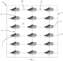
- Fig. 1 shows an embodiment of a hanging device 1 according to the invention for presenting shoes 4 as objects.
- the hanging device 1 comprises a grid field 2, which is constructed from five vertical profiles 21 and eight horizontal profiles 22.
- the vertical profiles 21 are each composed of seven vertical struts 211 arranged in a line as segments, which merge into one another via intersections 24.
- the horizontal profiles are each composed of four horizontal struts 221 arranged in a line as segments, which merge into one another via intersections 24.
- the vertical profiles 21 and the horizontal profiles 22 are each in a connected at right angles. This creates grid field 2 with twenty-eight cells 23, which appear rectangular in the view.
- the suspension device 1 further comprises eighteen primary beams 3.
- the primary beams 3 are mounted at the intersections 24 between vertical profiles 21 and horizontal profiles 22, as described in more detail below. Each of the primary beams 3 supports one of the shoes 4, so that the suspension device 1 presents eighteen shoes 4.
- FIG. 2 A perspective view of one of the primary supports 3 mounted on the grid field 2 without a shoe 4 is shown.
- the primary support 3 comprises a support section 32 and a mounting section 31.
- the support section 32 is designed like a tray or floor and has a flat surface 321 on which, for example, one of the shoes 4 can be placed.
- the mounting section 31 has two parallel hook parts 311 and a support part 312 arranged between them.
- the support part 312 and the support section 32 are plate-shaped and lie in one plane.
- the hook parts 311 each have a vertical suspension area 3113 that extends upward at a right angle to the support part 312 and, at its upper end, merges into a horizontally extending support area 3112.
- the vertical profiles 21 and the horizontal profiles 22 each have a rectangular cross-section.
- the larger edges of the cross-section are significantly longer than the smaller edges, so that the vertical profiles 21 and the horizontal profiles 22 are narrow.
- the vertical profiles 21 and the horizontal profiles 22 are connected to each other such that the narrow sides are aligned toward an open front and an open rear of the grid field 2.
- the wide sides of the vertical profiles 21 and the horizontal profiles 22 are aligned toward the cells 23.
- the hook parts 31 each partially encompass a horizontal strut 221 of one of the horizontal profiles 22.
- the left hook part 31 encompasses the horizontal strut 221 of one of the horizontal profiles 22 on the left side of one of the vertical profiles 21, and the right hook part 31 encompasses the horizontal strut 221 of the same horizontal profile 22 on the right side of the same vertical profile. 21.
- the support part 312 of the mounting section 31 of the primary support 3 is provided with a profile recess 3121 open in the direction of the vertical profile 21.
- the profile recess 3121 is designed according to the shape of the vertical struts 211.
- the vertical strut 211 which adjoins the horizontal struts 221, on which the hook parts 311 rest as described above, is received in the profile recess 3121, so that the support part 312 partially encompasses this vertical strut 211. In this way, the primary support 3 is supported in addition to the connection between the hook parts 311 and the horizontal struts 221.
- a moment generated by a load acting on the support surface 321 or a torque acting on the hook parts 311 can be absorbed by the vertical strut 21.
- This enables relatively heavy objects to be arranged stably on the primary support 3.
- the primary support 3 is secured against lateral or horizontal displacement by the vertical strut 211 located in the profile recess 3121.
- Fig. 3 It can be seen that the primary support 3 is formed from a sheet metal. The sheet metal is cut accordingly, and the hook parts 311 are bent upward from the rest of the primary support 3. The hook parts 311 run parallel to each other.
- Fig. 4 the suspension device 1 is shown with two identical primary beams 3 mounted at a single intersection 24.
- a first primary beam 3 is mounted on the grid field 2 from the front, and a second primary support 3 from the rear.
- the two different distances 313 and 314 of the hook parts 311 from the profile recess 3121, as described above, allow the hook sections 311 to pass each other, thus allowing the same horizontal sections 221 and vertical section 211 to be hung from both sides.
- the profile recesses 3121 are dimensioned such that they encompass the vertical struts 211 by slightly less than half the depth of the vertical struts 211.
- Fig. 4 It can be seen that the hook parts 311 are equipped with a nose 3111.
- the hook parts 311 each extend downwards from the end of the support area 3112 opposite the suspension area 3113 and slightly back towards the suspension area 3113.
- Fig. 5 to Fig. 8 show the primary beam 3 during assembly on the grid field 2.
- Fig. 5 It can be seen that the primary carrier is inserted diagonally downwards into the grid field 2.
- the hook parts 311 are inserted into two horizontally adjacent cells 23.
- the primary support is moved vertically downwards when the hook parts 31 are inserted into the cells 23 so far that the lugs 3111 are completely behind the vertical struts 22.
- the primary support 3 is still aligned quasi diagonally.
- the primary beam 3 When the primary beam 3 is lowered so far that the hook sections 31 touch the vertical struts 22, the primary beam 3 is moved as shown in Fig. 7 shown, is moved horizontally to the right. The left ends of the horizontal struts 22 are inserted between the lugs 3111 and the support areas 3112.
- the primary support 3 When the primary support 3 is moved to the right so far that the horizontal struts 221 rest horizontally against the hook parts 31, the primary support is lowered or rotated clockwise until the support areas 3112 rest on the horizontal struts 22 and the vertical strut 211 is inserted maximally into the profile holder 3121. As in Fig. 9 As can be seen, the lugs 3111 together with the support areas 3112 engage the left ends of the horizontal struts 221. In this way, the primary support 3 is securely and stably attached to the grid field 2.
- the term “comprising” and derivatives thereof does not exclude other elements or steps.
- the indefinite article “a” or “an” and derivatives thereof does not exclude a plurality.
- the functions of several features listed in the claims may be performed by a single unit or step.
- the terms “about” and “approximately” in connection with a given numerical value or range may refer to a value or range that is within 20%, within 10%, within 5%, or within 2% of the given value or range.
Landscapes
- Holders For Apparel And Elements Relating To Apparel (AREA)
- Display Racks (AREA)
Description
- Die Erfindung betrifft eine Aufhängevorrichtung gemäss dem Oberbegriff des unabhängigen Anspruchs 1.
- Solche Aufhängevorrichtungen mit einer Mehrzahl von Vertikalprofilen, einer Mehrzahl von Horizontalprofilen und zumindest einem Primärträger, bei dem die Vertikalprofile und die Horizontalprofile zu einem Gitterfeld zusammengebaut sind, das Gitterfeld eine Mehrzahl von systematisch angeordneten Zellen aufweist, die jeweils von Segmenten zweier der Horizontalprofile und zweier der Vertikalprofile umgeben sind, die Zellen des Gitterfelds zumindest zu einer Vorderseite offen sind, und der Primärträger einen zum lösbaren Einhängen in das Gitterfeld ausgebildeten Montageabschnitt und einen zum Anordnen zumindest eines der Gegenstände ausgebildeten Tragabschnitt aufweist, können zur Präsentation von Gegenständen beispielsweise in Verkaufsgeschäften oder Messen eingesetzt werden.
- Zur Präsentation von Artikeln in Verkaufsgeschäften oder auf Messen sind Systeme bekannt, bei denen Primärträger an einer Tragstruktur flexibel montierbar sind. Die Primärträger können dabei angepasst auf die zu präsentierenden Artikel ausgestaltet sein. Beispielsweise können sie Stangen zum Aufhängen von Artikeln wie beispielsweise Kleider aufweisen oder Böden beziehungsweise Tablare zum Auflegen diverser verschiedener Gegenstände. Als Tragstrukturen werden beispielsweise Wände, an denen die Primärträger befestigt werden können, Regale zum Versehen mit Regalböden oder Ähnlichem oder Gerüste eingesetzt.
- Aus der
WO 2011/109914 A1 ist eine Aufhängevorrichtung bekannt, bei der als Tragstruktur ein aus Vertikalstegen und Horizontalstegen zusammengebautes Gitterfeld eingesetzt wird. Das Gitterfeld lässt sich an einer Wand anordnen oder freistehend im Raum aufstellen. Die Aufhängevorrichtung umfasst weiter Primärträger die in einzelne Zellen des Gitterfeldes einsgesetzt werden können. Insbesondere sind die Primärträger jeweils mit einem Steckteil ausgestattet, der so in eine Zelle eingesetzt werden kann, dass er auf dem unteren Horizontalsteg aufliegt und gleichzeitig den oberen Horizontalsteg hintergreift. Ausser dem sind die Steckteile so ausgestaltet, dass in die gleiche Zelle gleichzeitig von beiden Seiten ein Primärträger eingehängt werden können. - Obwohl die Aufhängevorrichtung eine effiziente und flexible Bestückung mit Primärträgern ermöglicht, ist sie bezüglich der Position der Primärträger auf die Zellen begrenzt. Zudem sind die Steckteile vergleichsweise kompliziert aufgebaut und insbesondere bei verhältnismässig kleinen Zellen eher umständlich einzuhängen. Aus der
US 4,795,039 A ist eine andere Aufhängevorrichtung bekannt. - Der vorliegenden Erfindung liegt die Aufgabe zugrunde, einen alternativen Aufhängemechanismus einer Aufhängevorrichtung beziehungsweise eines Primärträgers vorzuschlagen, der ein effizientes und flexibles Befestigen von Primärträgern an einem Gitterfeld ermöglicht.
- Die Aufgabe wird erfindungsgemäss durch eine Aufhängevorrichtung gelöst, wie sie im unabhängigen Anspruch 1 definiert ist. Vorteilhafte Ausführungsvarianten der Erfindung ergeben sich aus den abhängigen Ansprüchen.
- Das Wesen der Erfindung besteht im Folgenden: Eine Aufhängevorrichtung zur Präsentation von Gegenständen wie Waren in Verkaufsgeschäften oder auf Messen umfasst eine Mehrzahl von Vertikalprofilen, eine Mehrzahl von Horizontalprofilen und zumindest einen Primärträger. Die Vertikalprofile sind typischerweise längsförmig und im zusammengebauten Zustand quasi vertikal aufgerichtet. In analoger Weise sind auch die Horizontalprofile typischerweise längsförmig und im zusammengebauten Zustand quasi horizontal ausgerichtet. Dabei können die Vertikal- und Horizontalprofile so dimensioniert sein, dass sie sich jeweils über quasi die vollständige Höhe beziehungsweise Breite der Aufhängevorrichtung erstrecken. Auch können die Vertikal- und Horizontalprofile verhältnismässig kurze Bauteile sein oder umfassen, die aneinander befestigt werden. So kann beispielsweise ein einzelnes Vertikal- beziehungsweise Horizontalprofil aus mehreren in einer Linie liegenden Vertikal- beziehungsweise Horizontalstreben zusammengesetzt sein. Diese können beispielsweise über Kreuzungen miteinander verbunden sein.
- Die Vertikalprofile und die Horizontalprofile sind zu einem Gitterfeld zusammengebaut. Dazu können die Vertikal- und Horizontalprofile miteinander verbunden sein. Die Verbindung der Vertikal- und Horizontalprofile kann direkt oder auch indirekt über ein weiteres Bauteil verbunden sein. Auch kann die Verbindung fest beziehungsweise unlösbar oder reversibel lösbar sein. Beispielsweise können die Vertikal- und Horizontalprofile über Steckverbindungen, Verschrauben, Klemmen oder in ähnlicher Weise lösbar miteinander verbunden sein. Die Vertikalprofile und die Horizontalprofile können auch zu einem einstückigen Gitterfeld verbunden sein. Beispielsweise können dabei die Vertikal- und Horizontalprofile jeweils aus mehreren Vertikal- beziehungsweise Horizontalstreben zusammengesetzt sein, die über Kreuzungen ineinander übergehen.
- Das Gitterfeld weist eine Mehrzahl von bevorzugt systematisch angeordneten Zellen auf, die jeweils von Segmenten zweier der Horizontalprofile und zweier der Vertikalprofile umgeben sind. Die Zellen des Gitterfelds sind zumindest zu einer Vorderseite hin offen. Die Zellen können systematisch angeordnet sein, indem sich die Vertikal- und Horizontalprofile in regelmässigen Abständen kreuzen. Die Zellen weisen mit Vorteil eine rechteckige oder quadratische Form auf. Die Segmente der Vertikal- und Horizontalprofile werden jeweils durch die Abschnitte der Vertikal- und Horizontalprofile gebildet, welche eine der Zellen formen. Dabei können die Segmente durch Vertikal- und Horizontalstreben gebildet sein, falls die Vertikal- und Horizontalprofile solche umfassen.
- Der Primärträger weist einen zum lösbaren Einhängen in das Gitterfeld ausgebildeten Montageabschnitt und einen zum Anordnen zumindest eines der Gegenstände ausgebildeten Tragabschnitt auf. Der Tragabschnitt kann auf den vorgehsehenen Einsatzzweck der Aufhängevorrichtung angepasst sein. Beispielsweise kann er eine Stange aufweisen, an die Kleider über Bügel als Sekundärträger oder auch ohne gehängt werden können.
- In einer vorteilhaften Ausführungsform ist der Tragabschnitt des Primärträgers insbesondere zum Auflegen des zumindest einen der Gegenstände als Bodenabschnitt ausgebildet. Dabei kann der Bodenabschnitt eben geformt sein, sodass auf einfache Weise Artikel auf ihn aufgelegt werden können. Beispielsweise kann der Bodenabschnitt dimensioniert und geformt sein, um einen einzelnen Schuh oder ein Paar Schuhe aufzunehmen. So kann die Aufhängevorrichtung spezifisch zur Schuhpräsentation vorgesehen sein, bei welcher der erfindungsgemässe Aufhängemechanismus besonders vorteilhaft sein kann.
- Der Montageabschnitt des Primärträgers umfasst einen Hakenteil und einen Stützteil. Der Hakenteil des Montageabschnitts des Primärträgers ist dazu ausgeformt, eines der Horizontalprofile zumindest teilweise zu umgreifen. Der Begriff "umgreifen" bezieht sich in diesem Zusammenhang darauf, dass der Hakenteil zumindest teilweise um das Horizontalprofil herum angeordnet ist und dieses mit Vorteil zumindest abschnittsweise kontaktiert. Bei einem Horizontalprofil, das beispielsweise vier- oder mehrkantrohrartig ausgebildet ist, kann der Hakenteil das Vertikalprofil umgreifen, indem er an mehreren Seiten am Vertikalprofil anliegt. Dabei umgreift der Hakenteil das Vertikalprofil mit Vorteil von oben, sodass es in montiertem Zustand einerseits auf dem Vertikalprofil vertikal aufliegt und andererseits zumindest an einer Seite des Vertikalprofils horizontal anliegt.
- Der Stützteil des Montageabschnitts des Primärträgers ist dazu ausgeformt, an einem der Vertikalprofile anzuliegen, während der Hakenteil des Montageabschnitts des Primärträgers das eine der Horizontalprofile zumindest teilweise umgreift. Insbesondere kann dadurch der Montageabschnitt am Vertikalträger abstützen und Kräfte beziehungsweise Momente auf diesen übertragen. Wenn eine Last auf den Tragabschnitt wirkt, beispielsweise durch einen aufgelegten oder angehängten Gegenstand, so kann die Last unter anderem auch durch den Vertikalträger abgestützt werden. Dadurch kann eine besonderes stabile und tragfähige Konstruktion erreicht werden. Insbesondere kann auf diese Weise auch der Primärträger versetzt zu den Zellen angeordnet sein, was die Flexibilität und Variabilität des Systems erhöhen kann.
- Vorzugsweise ist der Primärträger monolithisch ausgebildet ist. Der Begriff "monolithisch" kann sich darauf beziehen, dass der Primärträger aus mehreren fest beziehungsweise ortsfest miteinander verbundenen Komponenten aufgebaut ist und so eine Einheit bildet. Dabei können die Komponenten miteinander verschraubt, vernietet, verklebt oder auf ähnliche Weise miteinander verbunden sein. Mit Vorteil ist der Primärträger aus einem Stück geformt. Besonder bevorzugt ist der Primärträger aus einem umgeformten Blech hergestellt. Auf diese Weise kann er effizient in einer stabilen beziehungsweise robusten Ausführung realisiert sein. Insbesondere kann er so beispielsweise automatisch in vergleichsweise wenigen und einfachen Arbeitsschritten hergestellt werden.
- Vorzugsweise umfasst der Hakenteil des Montageabschnitts des Primärträgers einen Auflagebereich, der dazu ausgebildet ist, auf dem einen der Horizontalprofile aufzuliegen, wenn der Hakenteil des Montageabschnitts des Primärträgers das eine der Horizontalprofile zumindest teilweise umgreift. Auf diese Weise kann der Hakenteil das Horizontalprofil von oben her so umgreifen, dass er stabil auf dem Horizontalprofil aufliegt.
- Vorzugsweise umfasst der Hakenteil des Montageabschnitts des Primärträgers einen Abhängbereich, der den Hakenteil des Montageabschnitts mit dem Tragabschnitt so verbindet, dass der Hakenteil des Montageabschnitts sich vom Tragabschnitt nach oben erstreckt, wenn der Hakenteil des Montageabschnitts des Primärträgers das eine der Horizontalprofile zumindest teilweise umgreift. So kann der Tragabschnitt unterhalb des einen der Horizontalprofile liegen. Dies ermöglicht eine stabile Dreipunktverbindung und ein Abstützen an der Vertikalstütz nahe eines besonders stabilen Orts, nämlich wo sich Vertikal- und Horizontalstützen kreuzen. Auch aus ästhetischen und Platzgründen kann eine solche Anordnung vorteilhaft sein.
- Dabei umfasst der Hakenteil des Montageabschnitts des Primärträgers vorzugsweise eine Nase, die auf der dem Abhängbereich des Hakenteils des Montageabschnitts des Primärträgers entgegengesetzten Seite des Horizontalprofils angeordnet ist und die unter das eine der Horizontalprofile greift, wenn der Hakenteil des Montageabschnitts des Primärträgers das eine der Horizontalprofile zumindest teilweise umgreift. Mit einer solchen Nase kann der Hakenteil und mit ihm der Primärträger gegen ein unbeabsichtigtes Abrutschen beziehungsweise horizontales Verschieben weg vom Gitterfeld gesichert werden.
- Vorzugsweise umfasst der Montageabschnitt des Primärträgers einen weiteren Hakenteil, der quasi identisch wie der Hakenteil des Montageabschnitts des Primärträgers geformt ist. Auf diese Weise ist der Primärträger mit mindestens zwei Hackenteilen ausgestattet. So ermöglicht der Montageabschnitt eine stabile und belastbare Befestigung des Primärträgers. Insbesondere kann auch eine seitliche Bewegung des montierten Primärträgers unterbunden oder vermindert werden.
- Dabei ist der Stützteil des Montageabschnitts des Primärträgers vorzugsweise zwischen dem Hakenteil des Montageabschnitts des Primärträgers und dem weiteren Hakenteil des Montageabschnitts des Primärträgers angeordnet. Mit einem so ausgestalteten Montageabschnitt kann der Primärträger in zwei benachbarten und durch ein Vertikalprofil getrennte Zellen des Gitterfelds aufgehängt montiert werden. Dies ermöglicht zusammen mit dem Stützteil eine besonder stabile und solide Befestigung des Primärträgers.
- Der Stützteil des Montageabschnitts des Primärträgers ist dazu ausgeformt, das eine der Vertikalprofile zumindest teilweise zu umgreifen, sodass eine seitliche Bewegung des Montageabschnitts zusätzlich unterbunden wird, während der Hakenteil des Montageabschnitts des Primärträgers das eine der Horizontalprofile zumindest teilweise umgreift. Dazu weist der Stützteil des Montageabschnitts des Primärträgers vorzugsweise eine Profilaussparung auf, in der das eine der Vertikalprofile liegt, während der Hakenteil des Montageabschnitts des Primärträgers das eine der Horizontalprofile zumindest teilweise umgreift. So kann der Primärträger weiter stabilisiert am Gitterfeld montiert werden.
- Dabei ist ein erster Abstand zwischen dem Hakenteil des Montageabschnitts des Primärträgers und dem einen der Vertikalprofile verschieden von einem zweiten Abstand zwischen dem weiteren Hakenteil des Montageabschnitts des Primärträgers und dem einen der Vertikalprofile, während der Hakenteil des Montageabschnitts des Primärträgers und der weitere Hakenteil des Montageabschnitts des Primärträgers das eine der Horizontalprofile zumindest teilweise umgreifen und das eine der Vertikalprofile in der Profilaussparung des Stützteils des Montageabschnitts des Primärträgers liegt. Eine solche Ausgestaltung des Primärträgers kann insbesondere vorteilhaft sein, wenn die Zellen des Gitterfelds zusätzlich zur Vorderseite auch zu einer Rückseite offen sind. Dann ermöglicht der unterschiedliche Abstand, der beiden Hakenteile zum Vertikalprofil, dass gleichzeitig an der Vorder- und an der Rückseite des Gitterfelds in der gleichen Kombination von Horizontal- und Vertikalprofilen jeweils ein solcher Primärträger montiert werden kann.
- Vorzugsweise sind der Tragabschnitt des Primärträgers und der Stützteil des Montageabschnitts des Primärträgers quasi plattenförmig in einer Ebene gebildet. Dies ermöglicht eine effiziente Herstellung des Primärträgers in einer robusten Ausführung. Dabei erstreckt sich der Hakenteil des Montageabschnitts des Primärträgers angewinkelt und insbesondere in einem quasi rechten Winkel zum Tragabschnitt des Primärträgers erstreckt.
- Die Horizontal- und Vertikalprofile können beispielsweise rohrförmig und aus einem Metall hergestellt sein. Bevorzugt weisen die Vertikalprofile und die Horizontalprofile jeweils einen quasi rechteckigen Querschnitt auf, so dass sie zwei parallele breite Seiten und zwei parallele schmale Seiten umfassen. Dabei sind die Zellen des Gitterfelds vorzugsweise jeweils durch die breiten Seiten der sie begrenzenden Vertikalprofile und Horizontalprofile gebildet sind. Eine solche Ausgestaltung der Vertikal- und Horizontalprofile beziehungsweise der Zellen ermöglicht eine vergleichsweise grossflächige Auflage des Hakenabschnitts, so dass verhältnismässig grosse Lasten effizient getragen und stabil positioniert werden können.
- Weiterhin wird ein Primärträger zum Anordnen von einem Gegenstand an einem aus Vertikalprofilen und Horizontalprofilen zusammengebauten Gitterfeld beschrieben. Dieser Primärträger umfasst einen zum lösbaren Einhängen im Gitterfeld ausgebildeten Montageabschnitt und einen zum Auflegen eines Gegenstands ausgebildeten Tragabschnitt. Der Montageabschnitt weist einen Hakenteil und einen Stützteil auf. Der Hakenteil des Montageabschnitts ist ausgeformt, eines der Horizontalprofile zumindest teilweise zu umgreifen. Der Stützteil des Montageabschnitts ist ausgeformt, an einem der Vertikalprofile anzuliegen, während der Hakenteil des Montageabschnitts das eine der Horizontalprofile zumindest teilweise umgreift.
- Mit dem Primärträger können die oben im Zusammenhang mit der erfindungsgemässen Aufhängevorrichtung beschriebenen Effekte und Vorteile auf effiziente Weise erreicht werden.
- Der Primärträger kann bevorzugt mit weiteren Merkmalen wie sie oben im Zusammenhang mit dem Primärträger der erfindungsgemässen Aufhängevorrichtung beschrieben sind, ausgestattet sein. Dies ermöglicht die Implementierung der oben im Zusammenhang mit den bevorzugten Ausführungsformen der Aufhängevorrichtung beschriebenen Effekte und Vorteile.
- Weitere vorteilhafte Ausgestaltungen der Erfindung ergeben sich aus der nachfolgenden Beschreibung von Ausführungsbeispielen der Erfindung mithilfe der schematischen Zeichnung. Insbesondere werden im Folgenden die erfindungsgemässe Aufhängevorrichtung und der Primärträger unter Bezugnahme auf die beigefügten Zeichnungen anhand von Ausführungsbeispielen detaillierter beschrieben. Es zeigen:
- Fig. 1
- eine Vorderansicht eines Ausführungsbeispiels einer erfindungsgemässen Aufhängevorrichtung mit einem Ausführungsbeispiel eines Primärträgers;
- Fig. 2
- eine perspektivische Ansicht des an einem Gitterfeld der Aufhängevorrichtung von
Fig. 1 montierten Primärträger vonFig. 1 ; - Fig. 3
- eine Aufsicht des Primärträgers von
Fig. 1 ; - Fig. 4
- eine perspektivische Ansicht von zwei am Gitterfeld der Aufhängevorrichtung von
Fig.1 montierten Primärträger vonFig. 1 ; - Fig. 5
- eine Seitenansicht des Primärträgers von
Fig. 1 während er zur Montage am Gitterfeld der Aufhängevorrichtung vonFig. 1 in das Gitterfeld eingeführt wird; - Fig. 6
- eine Seitenansicht des Primärträgers von
Fig. 1 während er zur Montage am Gitterfeld der Aufhängevorrichtung vonFig. 1 auf ein Vertikalprofil des Gitterfelds abgesenkt wird; - Fig. 7
- eine Seitenansicht des Primärträgers von
Fig. 1 während er zur Montage am Gitterfeld der Aufhängevorrichtung vonFig. 1 in das Vertikalprofil des Gitterfelds einrastet; - Fig. 8
- eine Seitenansicht des Primärträgers von
Fig. 1 während er zur Montage am Gitterfeld der Aufhängevorrichtung vonFig. 1 auf das Vertikalprofil des Gitterfelds abgelegt wird; und - Fig. 9
- eine Seitenansicht des Primärträgers von
Fig. 1 während er am Gitterfeld der Aufhängevorrichtung vonFig. 1 montiert ist. - Bestimmte Ausdrücke werden in der folgenden Beschreibung aus praktischen Gründen verwendet und sind nicht einschränkend zu verstehen. Die Wörter "rechts", "links", "unten" und "oben" bezeichnen Richtungen in der Zeichnung, auf die Bezug genommen wird. Die Ausdrücke "nach innen", "nach aussen" "unterhalb", "oberhalb", "links", "rechts" oder ähnliche werden zur Beschreibung der Anordnung bezeichneter Teile zueinander, der Bewegung bezeichneter Teile zueinander und der Richtungen hin zum oder weg vom geometrischen Mittelpunkt der Erfindung sowie benannter Teile derselben wie in den Fig. dargestellt verwendet. Diese räumlichen Relativangaben umfassen auch andere Positionen und Ausrichtungen als die in den Fig. dargestellten. Zum Beispiel wenn ein in den Fig. dargestelltes Teil umgedreht wird, sind Elemente oder Merkmale, die als "unterhalb" beschrieben sind, dann "oberhalb". Die Terminologie umfasst die oben ausdrücklich erwähnten Wörter, Ableitungen von denselben und Wörter ähnlicher Bedeutung.
- Sind in einer Figur zum Zweck zeichnerischer Eindeutigkeit Bezugszeichen enthalten, aber im unmittelbar zugehörigen Beschreibungstext nicht erwähnt, so wird auf deren Erläuterung in vorangehenden Figurenbeschreibungen Bezug genommen. Sind ausserdem im unmittelbar zu einer Figur gehörigen Beschreibungstext Bezugszeichen erwähnt, die in der zugehörigen Figur nicht enthalten sind, so wird auf die vorangehenden und nachstehenden Figuren verwiesen. Ähnliche Bezugszeichen in zwei oder mehreren Fig. stehen für ähnliche oder gleiche Elemente.
-
Fig. 1 zeigt ein Ausführungsbeispiel einer erfindungsgemässen Aufhängevorrichtung 1 zur Präsentation von Schuhen 4 als Gegenstände. Die Aufhängevorrichtung 1 umfasst ein Gitterfeld 2, das aus fünf Vertikalprofilen 21 und acht Horizontalprofilen 22 aufgebaut ist. Die Vertikalprofile 21 sind jeweils aus sieben in einer Linie stehenden Vertikalstreben 211 als Segmente zusammengesetzt, die über Kreuzungen 24 ineinander übergehen. In analoger Weise sind die Horizontalprofile jeweils aus vier in einer Linie stehenden Horizontalstreben 221 als Segmente zusammengesetzt, die über die Kreuzungen 24 ineinander übergehen. An den Kreuzungen 24 sind die Vertikalprofile 21 und die Horizontalprofile 22 jeweils in einem rechten Winkel miteinander verbunden. So wird das Gitterfeld 2 mit achtundzwanzig, in der Ansicht rechteckige Zellen 23 gebildet. - Die Aufhängevorrichtung 1 umfasst weiter achtzehn Primärträger 3. Die Primärträger 3 sind an den Kreuzungen 24 zwischen Vertikalprofilen 21 und Horizontalprofilen 22 montiert, wie dies unten detaillierter beschrieben ist. Jeder der Primärträger 3 trägt einen der Schuhe 4, sodass die Aufhängevorrichtung 1 achtzehn Schuhe 4 präsentiert.
- In
Fig. 2 ist eine perspektivische Ansicht eines der am Gitterfeld 2 montierten Primärträger 3 ohne Schuh 4 gezeigt. Der Primärträger 3 umfasst einen Tragabschnitt 32 und einen Montageabschnitt 31. Der Tragabschnitt 32 ist tablar- beziehungsweise bodenartig ausgebildet und weist eine ebene Oberfläche 321 auf, auf die beispielsweise einer der Schuhe 4 aufgestellt werden kann. - Der Montageabschnitt 31 weist zwei parallele Hakenteile 311 und einen dazwischen angeordneten Stützteil 312 auf. Der Stützteil 312 und der Tragabschnitt 32 sind plattenartig ausgeformt und liegen in einer Ebene. Die Hakenteile 311 weisen jeweils einen vertikalen Abhängbereich 3113 auf, der sich rechtwinklig zum Stützteil 312 nach oben erstreckt und an seinem oberen Ende in einen sich in horizontaler Richtung erstreckenden Auflagebereich 3112 übergeht.
- Die Vertikalprofile 21 und die Horizontalprofile 22 weisen jeweils einen rechteckigen Querschnitt auf. Dabei sind die grösseren Kanten des Querschnitts wesentlich länger als die kleineren Kanten, sodass die Vertikalprofile 21 und die Horizontalprofile 22 schmal geformt sind. Die Vertikalprofile 21 und die Horizontalprofile 22 sind so miteinander verbunden, dass die schmalen Seiten zu einer offenen Vorderseite und einer offenen Rückseite des Gitterfelds 2 hin ausgerichtet sind. Die breiten Seiten der Vertikalprofile 21 und der Horizontalprofile 22 sind zu den Zellen 23 hin ausgerichtet.
- Im in
Fig. 2 gezeigten montierten Zustand umgreifen die Hakenteile 31 jeweils eine Horizontalstrebe 221 eines der Horizontalprofile 22 teilweise. Insbesondere umgreift der linke Hakenteil 31 die Horizontalstrebe 221 einer der Horizontalprofile 22 auf der linken Seite einer der Vertikalprofile 21 und der rechte Hakenteil 31 die Horizontalstrebe 221 des gleichen Horizontalprofils 22 auf der rechten Seite des gleichen Vertikalprofils 21. Indem das Horizontprofil 22 so geformt und ausgerichtet ist, dass seine nach oben ragende Kante verhältnismässig breit beziehungsweise tief ist, und indem die Auflagebereiche 3112 passend dazu dimensioniert und geformt sind, wird ein stabiles Auflegen und und Abstützen der Hakenteile 311 auf die Horizontalstreben 221 von oben her ermöglicht. Der Primärträger 3 ist so stabil positioniert. - Der Stützteil 312 des Montageabschnitts 31 des Primärträgers 3 ist mit einer in Richtung des Vertikalprofils 21 geöffneten Profilaussparung 3121 ausgestattet. Insbesondere ist die Profilaussparung 3121 entsprechend der Form der Vertikalstreben 211 ausgebildet. Im in
Fig. 2 gezeigten montierten Zustand des Primärträgers 3 ist die von den Horizontalstreben 221, auf denen die Hakenteile 311 wie vorstehend beschrieben aufliegen, nach unten anschliessende Vertikalstrebe 211 in der Profilaussparung 3121 aufgenommen, sodass das Stützteil 312 diese Vertikalstrebe 211 teilweise umgreift. Auf diese Weise ist der Primärträger 3 zusätzlich zur Verbindung zwischen den Hakenteilen 311 und den Horizontalstreben 221 abgestützt. Beispielsweise kann so ein durch eine auf der Auflageoberfläche 321 wirkende Last erzeugtes Moment beziehungsweise an den Hakenteilen 311 wirkendes Drehmoment von der Vertikalstrebe 21 aufgenommen werden. Dies ermöglicht ein stabiles Anordnen von verhältnismässig schweren Gegenständen auf dem Primärträger 3. Zusätzlich wird der Primärträger 3 durch die in der Profilaussparung 3121 liegende Vertikalstrebe 211 gegen ein seitliches beziehungsweise horizontales Verschieben gesichert. -
Fig. 3 zeigt eine Aufsicht des Primärträgers 3. Dabei ist ersichtlich, dass der linke Hakenteil 311 in einem ersten Abstand 313 von der Profilaussparung 3121 des Stützteils 312 entfernt liegt und der rechte Hakenteil 311 in einem zweiten Abstand 314. Der linke erste Abstand 313 ist etwas grösser als der rechte zweite Abstand 314. Insbesondere ist der erste Abstand 313 um etwas mehr als die Hälfte der Dicke der Hakenteile 311 beziehungsweise der Blechstärke grösser dimensioniert als der rechte Abstand 314. - Weiter ist in
Fig. 3 ersichtlich, dass der Primärträger 3 aus einem Blech geformt ist. Dabei ist das Blech entsprechend zugeschnitten und die Hakenteile 311 sind vom Rest des Primärträgers 3 aus nach oben gebogen. Die Hakenteile 311 verlaufen parallel zueinander. - In
Fig. 4 ist die Aufhängevorrichtung 1 mit zwei an einer einzigen Kreuzung 24 montierten identischen Primärträgern 3 gezeigt. Insbesondere ist ein erster Primärträger 3 von der Vorderseite her am Gitterfeld 2 montiert und ein zweiter Primärträger 3 von der Rückseite her. Dabei wird durch die beiden wie oben unterschiedlichen Abstände 313 und 314 der Hakenteile 311 von der Profilaussparung 3121 ermöglicht, dass die Hakenabschnitte 311 aneinander vorbei kommen und so ein beidseitiges Behängen der gleichen Horizontalabschnitte 221 und Vertikalabschnitt 211 möglich ist. Zum gleichen Zweck sind die Profilaussparungen 3121 so dimensioniert, dass sie die Vertikalstreben 211 um etwas weniger als die Hälfte der Tiefe der Vertikalstreben 211 umgreifen. - Weiter ist in
Fig. 4 ersichtlich, dass die Hakenteile 311 mit einer Nase 3111 ausgestattet sind. Insbesondere erstrecken sich die Hakenteile 311 jeweils vom dem Abhängbereich 3113 gegenübeliegenden Ende des Auflagebereichs 3112 nach unten und etwas zurück in Richtung Abhängbereich 3113. -
Fig. 5 bis Fig. 8 zeigen den Primärträger 3 während der Montage am Gitterfeld 2. Dabei ist inFig. 5 ersichtlich, dass der Primärträger diagonal nach unten in das Gitterfeld 2 eingeführt wird. Insbesondere werden die Hakenteile 311 in zwei horizontal benachbarte Zellen 23 eingeführt. - Wie in
Fig. 6 dargestellt ist, wird der Primärträger vertikal nach unten bewegt, wenn die Hakenteile 31 so weit in die Zellen 23 eingeführt sind, dass die Nasen 3111 vollständig hinter den Vertikalstreben 22 liegen. Der Primärträger 3 ist dabei immer noch quasi diagonal ausgerichtet. - Wenn der Primärträger 3 so weit abgesenkt ist, dass die Hakenabschnitte 31 die Vertikalstreben 22 berühren, wird der Primärträger 3 wie in
Fig. 7 dargestellt horizontal nach rechts bewegt. Dabei werden die linken Enden der Horizontalstreben 22 zwischen die Nasen 3111 und den Auflagebreichen 3112 eingeführt. - Wenn der Primärträger 3 so weit nach rechts bewegt ist, dass die Horizontalstreben 221 horizontal an den Hakenteilen 31 anliegen, wird der Primärträger abgesenkt beziehungsweise im Uhrzeigersinn gedreht, bis die Auflagenbereiche 3112 auf den Horizontalstreben 22 aufliegen und die Vertikalstrebe 211 maximal in die Profilaufnahme 3121 eingeführt ist. Wie in
Fig. 9 ersichtlich ist, umgreifen die Nasen 3111 zusammen mit den Auflagebereichen 3112 die linken Enden der Horizontalstreben 221. So ist der Primärträger 3 sicher und stabil am Gitterfeld 2 befestigt. - Im Weiteren schliesst der Ausdruck "umfassen" und Ableitungen davon andere Elemente oder Schritte nicht aus. Ebenfalls schliesst der unbestimmte Artikel "ein" bzw. "eine" und Ableitungen davon eine Vielzahl nicht aus. Die Funktionen mehrerer in den Ansprüchen aufgeführter Merkmale können durch eine Einheit beziehungsweise einen Schritt erfüllt sein. Die Begriffe "im Wesentlichen", "etwa", "ungefähr", "quasi" und dergleichen in Verbindung mit einer Eigenschaft beziehungsweise einem Wert definieren insbesondere auch genau die Eigenschaft beziehungsweise genau den Wert. Die Begriffe "etwa" und "ungefähr" im Zusammenhang mit einem gegebenen Zahlenwert oder -bereich kann sich auf einen Wert beziehungsweise Bereich beziehen, der innerhalb 20%, innerhalb 10%, innerhalb 5% oder innerhalb 2% des gegebenen Werts beziehungsweise Bereichs liegt.
Claims (14)
- Aufhängevorrichtung (1) zur Präsentation von Gegenständen (4), miteiner Mehrzahl von Vertikalprofilen (21), einer Mehrzahl von Horizontalprofilen (22) und zumindest einem Primärträger (3), wobeidie Vertikalprofile (21) und die Horizontalprofile (22) zu einem Gitterfeld (2) zusammengebaut sind,das Gitterfeld (2) eine Mehrzahl von Zellen (23) aufweist, die jeweils von Segmenten (211, 221) zweier der Horizontalprofile (22) und zweier der Vertikalprofile (21) umgeben sind,die Zellen (23) des Gitterfelds (2) zumindest zu einer Vorderseite offen sind,der Primärträger (3) einen zum lösbaren Einhängen in das Gitterfeld (2) ausgebildeten Montageabschnitt (31) und einen zum Anordnen zumindest eines der Gegenstände ausgebildeten Tragabschnitt (32) aufweist, wobeider Montageabschnitt (31) des Primärträgers (3) einen Hakenteil (311) und einen Stützteil (312) aufweist,der Hakenteil (311) des Montageabschnitts (31) des Primärträgers (3) geformt ist, eines der Horizontalprofile (22) zumindest teilweise zu umgreifen, undder Stützteil (312) des Montageabschnitts (31) des Primärträgers (3) geformt ist, an einem der Vertikalprofile (21) anzuliegen, während der Hakenteil (311) des Montageabschnitts (31) des Primärträgers (3) das eine der Horizontalprofile (22) zumindest teilweise umgreift,dadurch gekennzeichnet, dassder Stützteil (312) des Montageabschnitts (31) des Primärträgers (3) geformt ist, das eine der Vertikalprofile (21) zumindest teilweise zu umgreifen, sodass eine seitliche Bewegung des Montageabschnitts (31) des Primärträgers (3) unterbunden wird, während der Hakenteil (311) des Montageabschnitts (31) des Primärträgers (3) das eine der Horizontalprofile (22) zumindest teilweise umgreift.
- Aufhängevorrichtung (1) nach Anspruch 1, wobei der Primärträger (3) monolithisch ausgebildet ist.
- Aufhängevorrichtung (1) nach Anspruch 1 oder 2, wobei der Hakenteil (311) des Montageabschnitts (31) des Primärträgers (3) einen Auflagebereich (3112) umfasst, der dazu ausgebildet ist, auf dem einen der Horizontalprofile (22) aufzuliegen, wenn der Hakenteil (311) des Montageabschnitts (31) des Primärträgers (3) das eine der Horizontalprofile (22) zumindest teilweise umgreift.
- Aufhängevorrichtung (1) nach einem der vorangehenden Ansprüche, wobei der Hakenteil (311) des Montageabschnitts (31) des Primärträgers (3) einen Abhängbereich (3113) umfasst, der den Hakenteil (311) des Montageabschnitts (31) mit dem Tragabschnitt (32) so verbindet, dass der Hakenteil (311) des Montageabschnitts (31) sich vom Tragabschnitt (32) nach oben erstreckt, wenn der Hakenteil (311) des Montageabschnitts (31) des Primärträgers (3) das eine der Horizontalprofile (22) zumindest teilweise umgreift.
- Aufhängevorrichtung (1) nach Anspruch 4, wobei der Hakenteil (311) des Montageabschnitts (31) des Primärträgers (3) eine Nase (3113) umfasst, die auf der dem Abhängbereich (3113) des Hakenteils (311) des Montageabschnitts (31) des Primärträgers (3) entgegengesetzten Seite des Horizontalprofils angeordnet ist und die unter das eine der Horizontalprofile (22) greift, wenn der Hakenteil (311) des Montageabschnitts (31) des Primärträgers (3) das eine der Horizontalprofile (22) zumindest teilweise umgreift.
- Aufhängevorrichtung (1) nach einem der vorangehenden Ansprüche, wobei der Montageabschnitt (31) des Primärträgers (3) einen weiteren Hakenteil (311) umfasst, der quasi identisch wie der Hakenteil (311) des Montageabschnitts (31) des Primärträgers (3) geformt ist.
- Aufhängevorrichtung (1) nach Anspruch 6, wobei der Stützteil (312) des Montageabschnitts (31) des Primärträgers (3) zwischen dem Hakenteil (311) des Montageabschnitts (31) des Primärträgers (3) und dem weiteren Hakenteil (311) des Montageabschnitts (31) des Primärträgers (3) angeordnet ist.
- Aufhängevorrichtung (1) nach einem der vorangehenden Ansprüche, wobei der Stützteil (312) des Montageabschnitts (31) des Primärträgers (3) eine Profilaussparung (3121) aufweist, in der das eine der Vertikalprofile (21) liegt, während der Hakenteil (311) des Montageabschnitts (31) des Primärträgers (3) das eine der Horizontalprofile (22) zumindest teilweise umgreift.
- Aufhängevorrichtung (1) nach Anspruch 6, wobei ein erster Abstand (313) zwischen dem Hakenteil (311) des Montageabschnitts (31) des Primärträgers (3) und dem einen der Vertikalprofile (21) verschieden ist von einem zweiten Abstand (314) zwischen dem weiteren Hakenteil (311) des Montageabschnitts (31) des Primärträgers (3) und dem einen der Vertikalprofile, während der Hakenteil (311) des Montageabschnitts (31) des Primärträgers (3) und der weitere Hakenteil (311) des Montageabschnitts (31) des Primärträgers (3) das eine der Horizontalprofile (22) zumindest teilweise umgreifen und das eine der Vertikalprofile (21) in der Profilaussparung (3121) des Stützteils (312) des Montageabschnitts (31) des Primärträgers (3) liegt.
- Aufhängevorrichtung (1) nach einem der vorangehenden Ansprüche, wobei der Primärträger (3) aus einem umgeformten Blech hergestellt ist.
- Aufhängevorrichtung (1) nach einem der vorangehenden Ansprüche, wobei der Tragabschnitt (32) des Primärträgers (3) und der Stützteil (312) des Montageabschnitts (31) des Primärträgers (3) quasi plattenförmig in einer Ebene gebildet sind.
- Aufhängevorrichtung (1) nach Anspruch 11, wobei sich der Hakenteil (311) des Montageabschnitts (31) des Primärträgers (3) angewinkelt und insbesondere in einem quasi rechten Winkel zum Tragabschnitt (32) des Primärträgers (3) erstreckt.
- Aufhängevorrichtung (1) nach einem der vorangehenden Ansprüche, wobei die Vertikalprofile (21) und die Horizontalprofile (22) jeweils einen quasi rechteckigen Querschnitt aufweisen, so dass sie zwei parallele breite Seiten und zwei parallele schmale Seiten aufweisen.
- Aufhängevorrichtung (1) nach Anspruch 13, wobei die Zellen (23) des Gitterfelds (2) jeweils durch die breiten Seiten der sie begrenzenden Vertikalprofile (21) und Horizontalprofile (22) gebildet sind.
Applications Claiming Priority (2)
| Application Number | Priority Date | Filing Date | Title |
|---|---|---|---|
| CH00164/20A CH717130A1 (de) | 2020-02-14 | 2020-02-14 | Aufhängevorrichtung und Primärträger zur Präsentation von Gegenständen. |
| PCT/EP2021/053513 WO2021160836A1 (de) | 2020-02-14 | 2021-02-12 | Aufhängevorrichtung und primärträger |
Publications (2)
| Publication Number | Publication Date |
|---|---|
| EP4103015A1 EP4103015A1 (de) | 2022-12-21 |
| EP4103015B1 true EP4103015B1 (de) | 2025-06-11 |
Family
ID=70165747
Family Applications (1)
| Application Number | Title | Priority Date | Filing Date |
|---|---|---|---|
| EP21705180.4A Active EP4103015B1 (de) | 2020-02-14 | 2021-02-12 | Aufhängevorrichtung |
Country Status (3)
| Country | Link |
|---|---|
| EP (1) | EP4103015B1 (de) |
| CH (1) | CH717130A1 (de) |
| WO (1) | WO2021160836A1 (de) |
Families Citing this family (1)
| Publication number | Priority date | Publication date | Assignee | Title |
|---|---|---|---|---|
| DE202024101542U1 (de) * | 2024-03-27 | 2025-07-01 | Serafini Besitz Gmbh & Co. Kg | Vorrichtung zur Präsentation von Gegenständen |
Family Cites Families (5)
| Publication number | Priority date | Publication date | Assignee | Title |
|---|---|---|---|---|
| DE1177916B (de) * | 1961-04-06 | 1964-09-10 | Joachim Lahr | Schuhausstellungsregal |
| US4795039A (en) * | 1986-04-17 | 1989-01-03 | J R Group Plc | Display apparatus |
| DE8909094U1 (de) * | 1989-07-24 | 1989-11-16 | Bachnick, Martina, 1000 Berlin | Wandelbares Regalsystem |
| US7178681B2 (en) * | 2004-05-28 | 2007-02-20 | The Libman Company | Display rack construction |
| DE202010003364U1 (de) * | 2010-03-09 | 2010-07-01 | Visplay International Ag | Aufhängevorrichtung zur Präsentation von Gegenständen |
-
2020
- 2020-02-14 CH CH00164/20A patent/CH717130A1/de unknown
-
2021
- 2021-02-12 WO PCT/EP2021/053513 patent/WO2021160836A1/de not_active Ceased
- 2021-02-12 EP EP21705180.4A patent/EP4103015B1/de active Active
Also Published As
| Publication number | Publication date |
|---|---|
| EP4103015A1 (de) | 2022-12-21 |
| CH717130A1 (de) | 2021-08-16 |
| WO2021160836A1 (de) | 2021-08-19 |
Similar Documents
| Publication | Publication Date | Title |
|---|---|---|
| DE60003891T2 (de) | Befestigungsvorrichtung mit einem an einer wand abgehängten stab | |
| WO2019238154A1 (de) | Einzelner gerüststiel | |
| CH717061A1 (de) | Struktursystem zum modularen Aufbau von Regalen und Regal. | |
| EP4103015B1 (de) | Aufhängevorrichtung | |
| CH630581A5 (en) | Dismountable shelving unit | |
| DE3515260C2 (de) | ||
| DE202004002701U1 (de) | Vorrichtung zum Anhängen von Artikeln oder zur Halterung einer Ablage | |
| CH658174A5 (de) | Warenpraesentiergestell. | |
| DE1654512A1 (de) | Verbindung fuer Konstruktionsteile | |
| CH712455A1 (de) | Adapter, Warenträger und Befestigungssystem. | |
| DE1297399B (de) | Aufhaengevorrichtung fuer Tierkaefige | |
| WO2006037549A1 (de) | Hilfsrahmen für einen fahrgestellrahmen eines nutzfahrzeugs | |
| EP1082923A2 (de) | Wandprofilleiste | |
| DE29622396U1 (de) | Regal | |
| DE202009001539U1 (de) | Beschlagsystem zur wandhängenden Montage von Möbelkorpussen | |
| EP0625619B1 (de) | Gerüstbühne | |
| DE1921671U (de) | Gestell mit an gelochten pfosten einhangbaren anbauteilen. | |
| DE102005056973B4 (de) | Etage mit Einhängeösen | |
| DE4426791C2 (de) | Vorrichtung mit Lamellen, insbesondere mit Metallamellen zur einhakbaren, eine Ummantelungsfläche bildenden Verkleidung | |
| DE202019101481U1 (de) | Kübelwagen | |
| DE10306537B4 (de) | System zur Präsentation von Gegenständen | |
| AT377425B (de) | Zerlegbares regal | |
| EP1092366A1 (de) | Regalaufbau | |
| EP0813278B1 (de) | Als Blechformteil hergestellte Kopfplatte | |
| EP0405228B1 (de) | Halterung für schnell montierbare Sitzbänke oder Sitzträger, insbesondere von Tribünen |
Legal Events
| Date | Code | Title | Description |
|---|---|---|---|
| STAA | Information on the status of an ep patent application or granted ep patent |
Free format text: STATUS: UNKNOWN |
|
| STAA | Information on the status of an ep patent application or granted ep patent |
Free format text: STATUS: THE INTERNATIONAL PUBLICATION HAS BEEN MADE |
|
| PUAI | Public reference made under article 153(3) epc to a published international application that has entered the european phase |
Free format text: ORIGINAL CODE: 0009012 |
|
| STAA | Information on the status of an ep patent application or granted ep patent |
Free format text: STATUS: REQUEST FOR EXAMINATION WAS MADE |
|
| 17P | Request for examination filed |
Effective date: 20220913 |
|
| AK | Designated contracting states |
Kind code of ref document: A1 Designated state(s): AL AT BE BG CH CY CZ DE DK EE ES FI FR GB GR HR HU IE IS IT LI LT LU LV MC MK MT NL NO PL PT RO RS SE SI SK SM TR |
|
| DAV | Request for validation of the european patent (deleted) | ||
| DAX | Request for extension of the european patent (deleted) | ||
| STAA | Information on the status of an ep patent application or granted ep patent |
Free format text: STATUS: EXAMINATION IS IN PROGRESS |
|
| 17Q | First examination report despatched |
Effective date: 20230928 |
|
| GRAP | Despatch of communication of intention to grant a patent |
Free format text: ORIGINAL CODE: EPIDOSNIGR1 |
|
| STAA | Information on the status of an ep patent application or granted ep patent |
Free format text: STATUS: GRANT OF PATENT IS INTENDED |
|
| INTG | Intention to grant announced |
Effective date: 20250103 |
|
| GRAS | Grant fee paid |
Free format text: ORIGINAL CODE: EPIDOSNIGR3 |
|
| GRAA | (expected) grant |
Free format text: ORIGINAL CODE: 0009210 |
|
| STAA | Information on the status of an ep patent application or granted ep patent |
Free format text: STATUS: THE PATENT HAS BEEN GRANTED |
|
| AK | Designated contracting states |
Kind code of ref document: B1 Designated state(s): AL AT BE BG CH CY CZ DE DK EE ES FI FR GB GR HR HU IE IS IT LI LT LU LV MC MK MT NL NO PL PT RO RS SE SI SK SM TR |
|
| REG | Reference to a national code |
Ref country code: GB Ref legal event code: FG4D Free format text: NOT ENGLISH |
|
| REG | Reference to a national code |
Ref country code: CH Ref legal event code: EP |
|
| REG | Reference to a national code |
Ref country code: IE Ref legal event code: FG4D Free format text: LANGUAGE OF EP DOCUMENT: GERMAN |
|
| REG | Reference to a national code |
Ref country code: DE Ref legal event code: R096 Ref document number: 502021007705 Country of ref document: DE |
|
| PG25 | Lapsed in a contracting state [announced via postgrant information from national office to epo] |
Ref country code: FI Free format text: LAPSE BECAUSE OF FAILURE TO SUBMIT A TRANSLATION OF THE DESCRIPTION OR TO PAY THE FEE WITHIN THE PRESCRIBED TIME-LIMIT Effective date: 20250611 Ref country code: ES Free format text: LAPSE BECAUSE OF FAILURE TO SUBMIT A TRANSLATION OF THE DESCRIPTION OR TO PAY THE FEE WITHIN THE PRESCRIBED TIME-LIMIT Effective date: 20250611 |
|
| REG | Reference to a national code |
Ref country code: LT Ref legal event code: MG9D |
|
| PG25 | Lapsed in a contracting state [announced via postgrant information from national office to epo] |
Ref country code: NO Free format text: LAPSE BECAUSE OF FAILURE TO SUBMIT A TRANSLATION OF THE DESCRIPTION OR TO PAY THE FEE WITHIN THE PRESCRIBED TIME-LIMIT Effective date: 20250911 Ref country code: GR Free format text: LAPSE BECAUSE OF FAILURE TO SUBMIT A TRANSLATION OF THE DESCRIPTION OR TO PAY THE FEE WITHIN THE PRESCRIBED TIME-LIMIT Effective date: 20250912 |
|
| REG | Reference to a national code |
Ref country code: NL Ref legal event code: MP Effective date: 20250611 |
|
| PG25 | Lapsed in a contracting state [announced via postgrant information from national office to epo] |
Ref country code: BG Free format text: LAPSE BECAUSE OF FAILURE TO SUBMIT A TRANSLATION OF THE DESCRIPTION OR TO PAY THE FEE WITHIN THE PRESCRIBED TIME-LIMIT Effective date: 20250611 |
|
| PG25 | Lapsed in a contracting state [announced via postgrant information from national office to epo] |
Ref country code: HR Free format text: LAPSE BECAUSE OF FAILURE TO SUBMIT A TRANSLATION OF THE DESCRIPTION OR TO PAY THE FEE WITHIN THE PRESCRIBED TIME-LIMIT Effective date: 20250611 |
|
| PG25 | Lapsed in a contracting state [announced via postgrant information from national office to epo] |
Ref country code: RS Free format text: LAPSE BECAUSE OF FAILURE TO SUBMIT A TRANSLATION OF THE DESCRIPTION OR TO PAY THE FEE WITHIN THE PRESCRIBED TIME-LIMIT Effective date: 20250911 |
|
| PG25 | Lapsed in a contracting state [announced via postgrant information from national office to epo] |
Ref country code: LV Free format text: LAPSE BECAUSE OF FAILURE TO SUBMIT A TRANSLATION OF THE DESCRIPTION OR TO PAY THE FEE WITHIN THE PRESCRIBED TIME-LIMIT Effective date: 20250611 |
|
| PG25 | Lapsed in a contracting state [announced via postgrant information from national office to epo] |
Ref country code: NL Free format text: LAPSE BECAUSE OF FAILURE TO SUBMIT A TRANSLATION OF THE DESCRIPTION OR TO PAY THE FEE WITHIN THE PRESCRIBED TIME-LIMIT Effective date: 20250611 |
|
| PG25 | Lapsed in a contracting state [announced via postgrant information from national office to epo] |
Ref country code: PT Free format text: LAPSE BECAUSE OF FAILURE TO SUBMIT A TRANSLATION OF THE DESCRIPTION OR TO PAY THE FEE WITHIN THE PRESCRIBED TIME-LIMIT Effective date: 20251013 |
|
| PG25 | Lapsed in a contracting state [announced via postgrant information from national office to epo] |
Ref country code: IS Free format text: LAPSE BECAUSE OF FAILURE TO SUBMIT A TRANSLATION OF THE DESCRIPTION OR TO PAY THE FEE WITHIN THE PRESCRIBED TIME-LIMIT Effective date: 20251011 |
|
| PG25 | Lapsed in a contracting state [announced via postgrant information from national office to epo] |
Ref country code: SM Free format text: LAPSE BECAUSE OF FAILURE TO SUBMIT A TRANSLATION OF THE DESCRIPTION OR TO PAY THE FEE WITHIN THE PRESCRIBED TIME-LIMIT Effective date: 20250611 |
|
| PG25 | Lapsed in a contracting state [announced via postgrant information from national office to epo] |
Ref country code: CZ Free format text: LAPSE BECAUSE OF FAILURE TO SUBMIT A TRANSLATION OF THE DESCRIPTION OR TO PAY THE FEE WITHIN THE PRESCRIBED TIME-LIMIT Effective date: 20250611 |
|
| PG25 | Lapsed in a contracting state [announced via postgrant information from national office to epo] |
Ref country code: PL Free format text: LAPSE BECAUSE OF FAILURE TO SUBMIT A TRANSLATION OF THE DESCRIPTION OR TO PAY THE FEE WITHIN THE PRESCRIBED TIME-LIMIT Effective date: 20250611 |
|
| PG25 | Lapsed in a contracting state [announced via postgrant information from national office to epo] |
Ref country code: EE Free format text: LAPSE BECAUSE OF FAILURE TO SUBMIT A TRANSLATION OF THE DESCRIPTION OR TO PAY THE FEE WITHIN THE PRESCRIBED TIME-LIMIT Effective date: 20250611 |
|
| PG25 | Lapsed in a contracting state [announced via postgrant information from national office to epo] |
Ref country code: SK Free format text: LAPSE BECAUSE OF FAILURE TO SUBMIT A TRANSLATION OF THE DESCRIPTION OR TO PAY THE FEE WITHIN THE PRESCRIBED TIME-LIMIT Effective date: 20250611 |