EP4102731A1 - Drahtlose stromversorgungsvorrichtung und drahtloses stromversorgungssystem - Google Patents
Drahtlose stromversorgungsvorrichtung und drahtloses stromversorgungssystem Download PDFInfo
- Publication number
- EP4102731A1 EP4102731A1 EP21750539.5A EP21750539A EP4102731A1 EP 4102731 A1 EP4102731 A1 EP 4102731A1 EP 21750539 A EP21750539 A EP 21750539A EP 4102731 A1 EP4102731 A1 EP 4102731A1
- Authority
- EP
- European Patent Office
- Prior art keywords
- power transmission
- during
- power
- wireless power
- unit
- Prior art date
- Legal status (The legal status is an assumption and is not a legal conclusion. Google has not performed a legal analysis and makes no representation as to the accuracy of the status listed.)
- Pending
Links
- 230000005540 biological transmission Effects 0.000 claims abstract description 145
- 238000004891 communication Methods 0.000 claims abstract description 36
- 238000000034 method Methods 0.000 description 9
- 238000010586 diagram Methods 0.000 description 6
- 238000001228 spectrum Methods 0.000 description 6
- 230000003321 amplification Effects 0.000 description 5
- 238000003199 nucleic acid amplification method Methods 0.000 description 5
- 238000004519 manufacturing process Methods 0.000 description 4
- 230000007257 malfunction Effects 0.000 description 3
- 230000002238 attenuated effect Effects 0.000 description 2
- 230000003247 decreasing effect Effects 0.000 description 2
- 230000035945 sensitivity Effects 0.000 description 2
- 238000004364 calculation method Methods 0.000 description 1
- 239000000969 carrier Substances 0.000 description 1
- 238000006243 chemical reaction Methods 0.000 description 1
- 230000000694 effects Effects 0.000 description 1
- 238000012905 input function Methods 0.000 description 1
- 238000005457 optimization Methods 0.000 description 1
- 238000003466 welding Methods 0.000 description 1
Images


Classifications
-
- H—ELECTRICITY
- H02—GENERATION; CONVERSION OR DISTRIBUTION OF ELECTRIC POWER
- H02J—CIRCUIT ARRANGEMENTS OR SYSTEMS FOR SUPPLYING OR DISTRIBUTING ELECTRIC POWER; SYSTEMS FOR STORING ELECTRIC ENERGY
- H02J50/00—Circuit arrangements or systems for wireless supply or distribution of electric power
- H02J50/20—Circuit arrangements or systems for wireless supply or distribution of electric power using microwaves or radio frequency waves
- H02J50/23—Circuit arrangements or systems for wireless supply or distribution of electric power using microwaves or radio frequency waves characterised by the type of transmitting antennas, e.g. directional array antennas or Yagi antennas
-
- H—ELECTRICITY
- H02—GENERATION; CONVERSION OR DISTRIBUTION OF ELECTRIC POWER
- H02J—CIRCUIT ARRANGEMENTS OR SYSTEMS FOR SUPPLYING OR DISTRIBUTING ELECTRIC POWER; SYSTEMS FOR STORING ELECTRIC ENERGY
- H02J50/00—Circuit arrangements or systems for wireless supply or distribution of electric power
- H02J50/20—Circuit arrangements or systems for wireless supply or distribution of electric power using microwaves or radio frequency waves
-
- H—ELECTRICITY
- H02—GENERATION; CONVERSION OR DISTRIBUTION OF ELECTRIC POWER
- H02J—CIRCUIT ARRANGEMENTS OR SYSTEMS FOR SUPPLYING OR DISTRIBUTING ELECTRIC POWER; SYSTEMS FOR STORING ELECTRIC ENERGY
- H02J50/00—Circuit arrangements or systems for wireless supply or distribution of electric power
- H02J50/80—Circuit arrangements or systems for wireless supply or distribution of electric power involving the exchange of data, concerning supply or distribution of electric power, between transmitting devices and receiving devices
-
- H—ELECTRICITY
- H04—ELECTRIC COMMUNICATION TECHNIQUE
- H04B—TRANSMISSION
- H04B5/00—Near-field transmission systems, e.g. inductive or capacitive transmission systems
- H04B5/70—Near-field transmission systems, e.g. inductive or capacitive transmission systems specially adapted for specific purposes
- H04B5/72—Near-field transmission systems, e.g. inductive or capacitive transmission systems specially adapted for specific purposes for local intradevice communication
-
- H—ELECTRICITY
- H04—ELECTRIC COMMUNICATION TECHNIQUE
- H04B—TRANSMISSION
- H04B5/00—Near-field transmission systems, e.g. inductive or capacitive transmission systems
- H04B5/70—Near-field transmission systems, e.g. inductive or capacitive transmission systems specially adapted for specific purposes
- H04B5/77—Near-field transmission systems, e.g. inductive or capacitive transmission systems specially adapted for specific purposes for interrogation
-
- H—ELECTRICITY
- H04—ELECTRIC COMMUNICATION TECHNIQUE
- H04B—TRANSMISSION
- H04B5/00—Near-field transmission systems, e.g. inductive or capacitive transmission systems
- H04B5/70—Near-field transmission systems, e.g. inductive or capacitive transmission systems specially adapted for specific purposes
- H04B5/79—Near-field transmission systems, e.g. inductive or capacitive transmission systems specially adapted for specific purposes for data transfer in combination with power transfer
Definitions
- the present invention relates to a wireless power transmitter that wirelessly transmits power using microwaves and to a wireless power transmission system.
- Wireless power transmission has been used recently in various fields to transmit power contactlessly.
- microwave power transmission can transmit power over long distances, and be effectively used in, for example, radio frequency identifier (RFID) systems.
- RFID radio frequency identifier
- Such microwave power transmission is expected to increase transmission output to transmit power over longer distances.
- the increased transmission output may cause issues associated with interference with nearby devices being affected by radio waves for power transmission. Interference can have three possible issues.
- a host unit communicates with a secondary unit to optimize the amplitude and the phase of an antenna in the host unit, and controls the directivity of the antenna (propagation path control). This can improve power transmission efficiency.
- the communication between the host unit and the secondary unit in the propagation path control uses a modulated center frequency, thus expanding the power spectrum.
- the expanded power spectrum with the increased transmission output can cause interference with adjacent channels and disturbances of other systems.
- Patent Document 1 describes a technique for using different frequency bands for communication signals and for power transmission radio waves for transmitting power.
- the frequency band of 2.4 GHz is used for communication signals
- the frequency band of 5 GHz is used for power transmission radio waves.
- Patent Document 1 JP 2019-97302 A
- Patent Document 1 with increased power, the power transmission radio waves using the less congested frequency band of 5 GHz can reduce interference with nearby devices caused by the power transmission radio waves.
- a wireless power transmitter using two different frequency bands includes two radio frequency (RF) circuits for wireless communication. This complicates the structure of the wireless power transmitter.
- RF radio frequency
- Propagation path control can be performed with two methods.
- One method is to estimate the characteristics of a propagation path between the host unit and the secondary unit (propagation path estimation), and to adjust the directivity of the antenna to be optimal for the estimated characteristics of the propagation path.
- the other method is to estimate, with the host unit, the direction of the secondary unit (direction estimation), and to adjust the directivity of the antenna to allow the antenna to face in the estimated direction of the secondary unit.
- the propagation path estimation allows power transmission to the secondary unit in an optimal direction although the direction of the secondary unit is different from an optimum direction in which the power is transmitted to the secondary unit due to, for example, obstructions.
- the propagation path estimation provides more effective optimization of the directivity of the antenna.
- a propagation path for radio waves depends on the frequency of the radio waves.
- the propagation path cannot be estimated unless the communication signal and the power transmission signal have the same frequency.
- one or more aspects of the present invention are directed to a wireless power transmitter and a wireless power transmission system each with a simple structure that can reduce interference with nearby devices for power transmission radio waves having increased power.
- a wireless power transmitter is a wireless power transmitter as a host unit in a wireless power transmission system.
- the wireless power transmitter includes an antenna having adjustable directivity.
- the host unit transmits power to a secondary unit in the wireless power transmission system during a propagation path control period and during a power transmission period.
- the propagation path control period and the power transmission period are temporally divided from each other.
- the host unit communicates with the secondary unit to adjust the directivity of the antenna.
- the host unit transmits a power transmission radio wave while maintaining the directivity of the antenna adjusted during the propagation path control period.
- the host unit transmits, through the antenna, a communication signal during the propagation path control period and the power transmission radio wave to have a transmission output of the power transmission radio wave during the power transmission period being greater than a transmission output of the communication signal during the propagation path control period.
- the propagation path control period and the power transmission period are temporally divided from each other.
- the above structure can decrease the transmission output to reduce interference.
- the above structure can increase the transmission output while reducing the expansion of the power spectrum to reduce interference with nearby devices for the power transmission radio waves having increased power.
- a single radio frequency (RF) circuit for wireless communication can transmit different transmission outputs between during the propagation path control period and during the power transmission period, thus avoiding a complicated structure of the wireless power transmitter.
- the above wireless power transmitter may transmit a carrier signal in the communication signal as the power transmission radio wave.
- the power transmission radio waves during the power transmission period are unmodulated.
- the power spectrum does not expand as the transmission output increases.
- Such power transmission radio waves do not interfere with adjacent frequency channels and do not affect nearby other devices (receivers) using the adjacent channels.
- the power transmission radio waves, or an unmodulated signal, reaching the nearby other devices does not cause malfunctions of the devices.
- a wireless power transmission system is a system for wireless power transmission.
- the system includes a primary unit including the wireless power transmitter described above, and a secondary unit.
- the primary unit wirelessly transmits power to the secondary unit.
- the host unit may bidirectionally communicate with the secondary unit. During the power transmission period, the host unit may unidirectionally transmit power to the secondary unit.
- communication between the host unit and the secondary unit during the propagation path control period may be passive communication.
- the secondary unit having low reception sensitivity in passive communication does not receive radio waves from host units in adjacent identical systems, preventing interference with the adjacent systems.
- the wireless power transmitter and the wireless power transmission system according to the above aspects of the present invention each have the simple structure and can reduce interference with nearby devices for the power transmission radio waves having increased power.
- FIG. 1 is a block diagram of a host unit (wireless power transmitter) 100 included in a wireless power transmission system (hereafter, the system) according to an embodiment, showing its basic structure.
- FIG. 2 is a block diagram of a secondary unit 200 included in the system, showing its basic structure. In the system, multiple secondary units 200 are usable for a single host unit 100.
- the host unit 100 includes a processor 101, a digital-to-analog converter (DAC) 102, a carrier signal oscillator 103, a first mixer 104, a transmission amplifier 105, a transmission-reception separator 106, a reception amplifier 107, a second mixer 108, an analog-to-digital converter (ADC) 109, and an antenna 110.
- DAC digital-to-analog converter
- ADC analog-to-digital converter
- the processor 101 is a main controller controlling the overall host unit 100, and in particular, controlling its communication and directivity during power transmission.
- the DAC 102 converts data generated by the processor 101 from digital to analog.
- the carrier signal oscillator 103 generates carrier signals (carriers).
- the carrier signals are microwave signals.
- the first mixer 104 combines the analog data resulting from the conversion with the carrier signal. An output from the first mixer 104 is amplified by the transmission amplifier 105, and is then transmitted to the secondary unit 200 through the transmission-reception separator 106 and the antenna 110.
- the transmission amplifier 105 can switch the amplification factor as controlled by the processor 101. This allows the transmission amplifier 105 to transmit two or more power outputs, or a continuously variable power output.
- the antenna 110 is an array antenna including n antenna elements. The amplitudes and phases of the antenna elements are electrically controlled to control the directivity of the antenna 110. The directivity of the antenna 110 is controlled by an antenna controller 101a included in the processor 101.
- the host unit 100 also receives a communication signal from the secondary unit 200.
- the communication signal (reception signal) from the secondary unit 200 is transmitted to the reception amplifier 107 through the antenna 110 and the transmission-reception separator 106.
- the communication signal is then amplified by the reception amplifier 107.
- the transmission-reception separator 106 separates a path for a transmission signal transmitted from the host unit 100 from a path for the reception signal received by the host unit 100.
- the reception signal amplified by the reception amplifier 107 is combined with, with the second mixer 108, the carrier signal generated by the carrier signal oscillator 103.
- the carrier signal is combined for quadrature demodulation. In other words, amplitude information and phase information extracted through the quadrature demodulation are used to perform propagation path estimation.
- high frequency components are removed through a low-pass filter (LPF).
- An output from the second mixer 108 (a combined wave of the reception signal and the carrier signal) is converted from analog to digital by the ADC 109, and is then input into the processor 101.
- the processor 101 controls the communication and directivity in accordance with the input reception signal.
- the secondary unit 200 includes a matching circuit 201, a demodulation circuit 202, a rectification circuit 203, a modulation circuit 204, a controller 205, a load 206, and an antenna 207.
- the matching circuit 201 matches the impedance of the antenna 207 with the impedance of the demodulation circuit 202, and with the impedance of the modulation circuit 204.
- the demodulation circuit 202 demodulates a reception signal (communication signal) received from the host unit 100.
- the rectification circuit 203 converts a reception signal (power transmission radio waves) from the host unit 100 to a direct current, and supplies the direct current as operation power to other processors. In FIG. 2 , power transmission lines from the rectification circuit 203 are indicated by dashed arrows.
- the modulation circuit 204 modulates a transmission signal to be transmitted by the secondary unit 200.
- the controller 205 controls the overall secondary unit 200 and the load 206.
- the load 206 is a functional unit (e.g., a sensor) having a predetermined function.
- the load 206 has various output and input functions to operate under the control of the controller 205.
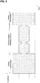
- FIG. 3 is a graph showing the radio wave intensity of a signal transmitted from the host unit 100.
- FIG. 4 is a flowchart of the method (control in the host unit 100) for transmitting power in the system.
- the host unit 100 transmits power to the secondary unit 200 during a communication-directivity control period (propagation path control period), and during a power transmission period.
- the communication-directivity control period and the power transmission period are temporally divided from each other.
- the power transmission period and the communication-directivity control period may not be consecutive.
- the secondary unit 200 may start by using power accumulated during the power transmission period, or by using power regenerated from a signal alone for communication in the communication signal.
- the host unit 100 sets an amplification factor of the transmission amplifier 105 to a level for communication (low power) (S1).
- the host unit 100 bidirectionally communicates with the secondary unit 200.
- the propagation path control is performed based on the results from this communication.
- the host unit 100 transmits a communication signal to the secondary unit 200 (S2), and receives a return signal from the secondary unit 200 (S3).
- the host unit 100 estimates a propagation coefficient and calculates a transmission weight (S4).
- the host unit 100 controls the amplitudes and the phases of the antenna elements in the antenna 110 to optimize the directivity of the antenna 110 (propagation path control) based on the calculation results. Optimizing the directivity of the antenna can improve power transmission efficiency during a subsequent power transmission period.
- Such propagation path control is a known technique.
- An initial power transmission period for starting the secondary unit 200 is shown in FIG. 3 . During this initial power transmission period, the directivity of the antenna 110 is not optimized.
- the host unit 100 sets the amplification factor of the transmission amplifier 105 to a level for transmitting power (high power) (S5) and then transmits power transmission radio waves to the secondary unit 200 (S6).
- the host unit 100 unidirectionally transmits the radio waves to the secondary unit 200 to transmit power.
- the power transmission radio waves transmitted from the host unit 100 during the power transmission period represent an unmodulated signal.
- the processor 101 in the host unit 100 does not generate data to be superimposed on the carrier signal, and causes the carrier signal alone to be amplified and transmitted as the power transmission radio waves.
- the system has transmission outputs from the host unit 100 different during the power transmission period and during the communication-directivity control period.
- the transmission output during the power transmission period is increased more than the transmission output during the communication-directivity control period.
- the increased transmission output allows power to be transmitted over longer distances.
- the transmission signal, or an unmodulated signal, during the power transmission period allows, with the transmission output being increased, transmission without expanding the power spectrum. This can avoid interference with other devices (receivers) using adjacent frequency channels outside the system. When reaching other devices, the radio waves, or the unmodulated signal, do not cause malfunctions of the devices.
- the decreased transmission output can reduce the expansion of the power spectrum and reduce radio wave interference.
- the same antenna 110 is used for transmission from the host unit 100 during the power transmission period and during the communication-directivity control period.
- the directivity of the antenna 110 adjusted (optimized) during the communication-directivity control period can be maintained during the subsequent power transmission period.
- the host unit 100 in the system has a single RF circuit (including the DAC 102, the carrier signal oscillator 103, the first mixer 104, and the transmission amplifier 105) for wireless communication, allowing the simple structure.
- the host unit 100 switches the amplification factor of the transmission amplifier 105.
- the transmission amplifier 105 is to transmit two or more power outputs or a continuously variable power output. Example structures of the transmission amplifier 105 will now be described with reference to FIGs. 5 and 6 .
- the transmission amplifier 105 includes a preamplifier 105a, a power amplifier 105b, and a variable attenuator 105c, which are connected in series.
- An input signal (RF in) input into the transmission amplifier 105 has the power amplified by the preamplifier 105a and the power amplifier 105b, and attenuated by the variable attenuator 105c.
- the transmission amplifier 105 adjusts power to be attenuated in the variable attenuator 105c in response to a control signal from the processor 101 to allow the output signal (RF out) to have multivalued power outputs or a continuously variable power output.
- the transmission amplifier 105 may directly adjust an amplification factor of the preamplifier 105a or the power amplifier 105b rather than using the variable attenuator 105c to allow the signal to have multivalued power outputs or a continuously variable power output.
- the transmission amplifier 105 includes a power divider 105d, a switch circuit 105e including multiple switch elements, multiple power amplifiers 105f, and a power combiner 105g.
- the power divider 105d equally divides the power of the signal (RF in) input into the transmission amplifier 105, and outputs the divided power to each of multiple signal lines.
- the multiple signal lines from the power divider 105d each are connected to the corresponding power amplifier 105f.
- the multiple signal lines from the power divider 105d are connected to the switch elements included in the switch circuit 105e. All the signal lines from the power divider 105d may not be connected to the switch elements. Some of the signal lines may not be connected to the switch elements.
- the switch circuit 105e can switch the switch elements between on and off in response to a control signal from the processor 101, and can switch the number of signals to be amplified by the power amplifiers 105f.
- the power combiner 105g combines outputs from the multiple power amplifiers 105f and generates an output signal (RF out).
- the transmission amplifier 105 can switch the number of signals to be amplified in response to the control signal from the processor 101 to allow the output signal (RF out) to have multivalued power outputs.
- the wireless power transmission system can be used effectively for, for example, a sensor system used on a production line at, for example, a factory.
- the sensor system On the production line at, for example, a factory, the sensor system is used for controlling the operations of various robots (e.g., welding robots or assembly robots).
- a power transmitter as a host unit wirelessly transmits power to wireless sensors (including sensors as loads) as secondary units.
- the powered wireless sensors perform predetermined sensing operations with the power.
- the system can reduce radio wave interference with adjacent frequency channels by decreasing the transmission output during the communication-directivity control period while increasing the transmission output during the power transmission period.
- factories using wireless devices e.g., RFIDs
- the same frequency band as this sensor system can install the sensor system.
- passive communication in which the secondary unit 200 transmits a connection for data transfer
- the secondary unit In the system, passive communication (in which the secondary unit 200 transmits a connection for data transfer) is effective for the communication between the host unit and the secondary unit during the communication-directivity control period.
- the secondary unit In passive communication, the secondary unit typically has lower reception sensitivity than in active communication, thus avoiding interference with the same sensor systems installed on adjacent production lines.
Landscapes
- Engineering & Computer Science (AREA)
- Computer Networks & Wireless Communication (AREA)
- Power Engineering (AREA)
- Signal Processing (AREA)
- Transmitters (AREA)
- Physics & Mathematics (AREA)
- Electromagnetism (AREA)
- Near-Field Transmission Systems (AREA)
- Mobile Radio Communication Systems (AREA)
Applications Claiming Priority (2)
| Application Number | Priority Date | Filing Date | Title |
|---|---|---|---|
| JP2020018521A JP2021125983A (ja) | 2020-02-06 | 2020-02-06 | ワイヤレス給電装置およびワイヤレス給電システム |
| PCT/JP2021/002943 WO2021157456A1 (ja) | 2020-02-06 | 2021-01-28 | ワイヤレス給電装置およびワイヤレス給電システム |
Publications (2)
| Publication Number | Publication Date |
|---|---|
| EP4102731A1 true EP4102731A1 (de) | 2022-12-14 |
| EP4102731A4 EP4102731A4 (de) | 2023-08-30 |
Family
ID=77199521
Family Applications (1)
| Application Number | Title | Priority Date | Filing Date |
|---|---|---|---|
| EP21750539.5A Pending EP4102731A4 (de) | 2020-02-06 | 2021-01-28 | Drahtlose stromversorgungsvorrichtung und drahtloses stromversorgungssystem |
Country Status (5)
| Country | Link |
|---|---|
| US (1) | US20230113648A1 (de) |
| EP (1) | EP4102731A4 (de) |
| JP (1) | JP2021125983A (de) |
| CN (1) | CN115004565A (de) |
| WO (1) | WO2021157456A1 (de) |
Families Citing this family (1)
| Publication number | Priority date | Publication date | Assignee | Title |
|---|---|---|---|---|
| CN116843161B (zh) * | 2023-08-25 | 2023-11-10 | 山东开创电气有限公司 | 一种煤矿井下掘进采煤设备远距离供电分析管理系统 |
Family Cites Families (21)
| Publication number | Priority date | Publication date | Assignee | Title |
|---|---|---|---|---|
| JP5270128B2 (ja) * | 2007-09-19 | 2013-08-21 | 株式会社ユニバーサルエンターテインメント | 無線icタグ読み取り装置 |
| US8497658B2 (en) * | 2009-01-22 | 2013-07-30 | Qualcomm Incorporated | Adaptive power control for wireless charging of devices |
| KR101822527B1 (ko) * | 2010-07-28 | 2018-01-26 | 가부시키가이샤 한도오따이 에네루기 켄큐쇼 | 무선 급전 시스템 및 무선 급전 방법 |
| JP2013009545A (ja) * | 2011-06-27 | 2013-01-10 | Panasonic Corp | 無線電力伝送システム及び給電装置 |
| CN102628550A (zh) * | 2012-03-29 | 2012-08-08 | 昆明迪森电气有限公司 | 无线供电通信照明手持仪及利用其的井盖系统 |
| EP2974076B1 (de) * | 2013-03-15 | 2018-10-31 | Facebook, Inc. | Verwendung von drahtlosfunk zur verwaltung des stromverbrauchs |
| JP6173057B2 (ja) * | 2013-06-11 | 2017-08-02 | キヤノン株式会社 | 給電装置、給電方法、プログラム及び記録媒体 |
| JP5839629B1 (ja) * | 2014-07-18 | 2016-01-06 | デクセリアルズ株式会社 | 非接触通信装置、アンテナ回路、アンテナ駆動装置、非接触給電装置、チューニング方法、ディスカバリ方法、およびこれらの方法を実現するプログラム |
| JP6337797B2 (ja) * | 2015-02-13 | 2018-06-06 | オムロン株式会社 | 無線給電制御システム、無線給電制御装置、無線給電制御方法、及び指向性情報生成方法 |
| CN104836592B (zh) * | 2015-04-02 | 2017-05-17 | 西安电子科技大学 | 无线携能通信装置 |
| US10027168B2 (en) * | 2015-09-22 | 2018-07-17 | Energous Corporation | Systems and methods for generating and transmitting wireless power transmission waves using antennas having a spacing that is selected by the transmitter |
| KR102423599B1 (ko) * | 2015-09-22 | 2022-07-22 | 삼성전자주식회사 | 무선 전력 송신기 및 상기 무선 전력 송신기의 제어 방법 |
| WO2017171435A1 (ko) * | 2016-03-31 | 2017-10-05 | 삼성전자 주식회사 | 무선 전력 송신 장치 및 그 제어 방법 |
| KR102623589B1 (ko) * | 2016-12-23 | 2024-01-11 | 삼성전자주식회사 | 무선 전력 송신기, 전자 장치 및 그 제어 방법 |
| JP6630712B2 (ja) * | 2017-10-30 | 2020-01-15 | 京セラ株式会社 | 測定方法、測定プログラム、及び測定装置 |
| JP7102126B2 (ja) * | 2017-10-31 | 2022-07-19 | キヤノン株式会社 | 給電機器、給電機器の制御方法、及び、プログラム |
| JP6802776B2 (ja) | 2017-11-22 | 2020-12-23 | 株式会社東芝 | 無線給電装置、無線受電端末及び無線給電方法 |
| KR102502548B1 (ko) * | 2018-04-25 | 2023-02-21 | 오시아 인크. | 지향성 무선 전력 및 무선 데이터 통신 |
| CN108767954B (zh) * | 2018-06-21 | 2020-09-18 | 深圳奥比中光科技有限公司 | 智能家居的远程无线充电系统、控制系统及方法 |
| JP7087742B2 (ja) * | 2018-07-06 | 2022-06-21 | オムロン株式会社 | 無線給電装置及び無線給電システム |
| JP7087795B2 (ja) | 2018-07-31 | 2022-06-21 | 東洋製罐株式会社 | 目薬点眼補助具および目薬点眼ユニット |
-
2020
- 2020-02-06 JP JP2020018521A patent/JP2021125983A/ja active Pending
-
2021
- 2021-01-28 WO PCT/JP2021/002943 patent/WO2021157456A1/ja unknown
- 2021-01-28 EP EP21750539.5A patent/EP4102731A4/de active Pending
- 2021-01-28 US US17/794,640 patent/US20230113648A1/en active Pending
- 2021-01-28 CN CN202180009378.6A patent/CN115004565A/zh active Pending
Also Published As
| Publication number | Publication date |
|---|---|
| CN115004565A (zh) | 2022-09-02 |
| EP4102731A4 (de) | 2023-08-30 |
| JP2021125983A (ja) | 2021-08-30 |
| WO2021157456A1 (ja) | 2021-08-12 |
| US20230113648A1 (en) | 2023-04-13 |
Similar Documents
| Publication | Publication Date | Title |
|---|---|---|
| EP2975781B1 (de) | Phasengesteuerte übertragungsvorrichtung | |
| KR101162857B1 (ko) | 전력 전송을 위한 송신장치 및 수신장치 | |
| CN112805938A (zh) | 一种信号放大电路及终端设备 | |
| US20210152022A1 (en) | Apparatus and method for performing transmission and reception of wireless power | |
| KR20100115685A (ko) | Tdd용 기지국 안테나의 송수신 타이밍 제어 방법 및 상기 방법이 적용된 기지국 안테나 | |
| US9100082B2 (en) | Radio communication system and a repeater | |
| EP4102731A1 (de) | Drahtlose stromversorgungsvorrichtung und drahtloses stromversorgungssystem | |
| KR20020008840A (ko) | 송신 안테나 다이버시티를 갖는 이중 코드 확산 스펙트럼통신 시스템 | |
| CN101238644A (zh) | 发射机延迟和相位调节 | |
| KR20130083104A (ko) | 무선 통신 시스템에서 기지국의 빔 보상 방법 및 장치 | |
| KR20180041470A (ko) | 상쇄루프를 이용한 적응형 위상반전 무선 전력 송신 장치 및 방법 | |
| KR101870389B1 (ko) | IoT 센서 네트워크 환경에서 근거리 저전력 수신 방법 및 RF 수신 장치 | |
| JP2017005647A (ja) | 位相制御装置及びアレーアンテナシステム | |
| KR100418251B1 (ko) | 전파탐지장치(beacon) | |
| JP4628992B2 (ja) | 無線送受信機 | |
| US11616533B2 (en) | Radio power transmission system and radio power transmission method | |
| JP2017005656A (ja) | 位相異常検出装置及びアレーアンテナシステム | |
| JP2803436B2 (ja) | 移動通信システムの無線基地局装置 | |
| KR20130073609A (ko) | 무선 통신 시스템의 전송 전력 제어 장치 및 방법 | |
| KR100526705B1 (ko) | 무선중계기의 전파간섭제거장치 및 그 전파간섭 제거방법 | |
| JP2001069053A (ja) | 指向性アンテナ装置 | |
| JP3813537B2 (ja) | Cdma移動通信基地局装置 | |
| KR0119559B1 (ko) | 무선 랜의 주파수 송수신 장치 | |
| JP2007150829A (ja) | 無線装置及び通信制御方法 | |
| KR20050067298A (ko) | 다중경로 송수신기의 위상제어방법 |
Legal Events
| Date | Code | Title | Description |
|---|---|---|---|
| STAA | Information on the status of an ep patent application or granted ep patent |
Free format text: STATUS: THE INTERNATIONAL PUBLICATION HAS BEEN MADE |
|
| PUAI | Public reference made under article 153(3) epc to a published international application that has entered the european phase |
Free format text: ORIGINAL CODE: 0009012 |
|
| STAA | Information on the status of an ep patent application or granted ep patent |
Free format text: STATUS: REQUEST FOR EXAMINATION WAS MADE |
|
| 17P | Request for examination filed |
Effective date: 20220712 |
|
| AK | Designated contracting states |
Kind code of ref document: A1 Designated state(s): AL AT BE BG CH CY CZ DE DK EE ES FI FR GB GR HR HU IE IS IT LI LT LU LV MC MK MT NL NO PL PT RO RS SE SI SK SM TR |
|
| DAV | Request for validation of the european patent (deleted) | ||
| DAX | Request for extension of the european patent (deleted) | ||
| A4 | Supplementary search report drawn up and despatched |
Effective date: 20230802 |
|
| RIC1 | Information provided on ipc code assigned before grant |
Ipc: H02J 50/80 20160101ALI20230727BHEP Ipc: H04B 5/00 20060101ALI20230727BHEP Ipc: H04B 1/59 20060101ALI20230727BHEP Ipc: H02J 50/90 20160101ALI20230727BHEP Ipc: H02J 50/20 20160101ALI20230727BHEP Ipc: H04B 5/02 20060101AFI20230727BHEP |