EP4100305B1 - Ensemble d'assise dans de multiples configurations dans un véhicule à deux roues - Google Patents
Ensemble d'assise dans de multiples configurations dans un véhicule à deux roues Download PDFInfo
- Publication number
- EP4100305B1 EP4100305B1 EP21706457.5A EP21706457A EP4100305B1 EP 4100305 B1 EP4100305 B1 EP 4100305B1 EP 21706457 A EP21706457 A EP 21706457A EP 4100305 B1 EP4100305 B1 EP 4100305B1
- Authority
- EP
- European Patent Office
- Prior art keywords
- seat
- seat pan
- coupling
- vehicle
- pan
- Prior art date
- Legal status (The legal status is an assumption and is not a legal conclusion. Google has not performed a legal analysis and makes no representation as to the accuracy of the status listed.)
- Active
Links
Images


Classifications
-
- B—PERFORMING OPERATIONS; TRANSPORTING
- B62—LAND VEHICLES FOR TRAVELLING OTHERWISE THAN ON RAILS
- B62J—CYCLE SADDLES OR SEATS; AUXILIARY DEVICES OR ACCESSORIES SPECIALLY ADAPTED TO CYCLES AND NOT OTHERWISE PROVIDED FOR, e.g. ARTICLE CARRIERS OR CYCLE PROTECTORS
- B62J1/00—Saddles or other seats for cycles; Arrangement thereof; Component parts
- B62J1/12—Box-shaped seats; Bench-type seats, e.g. dual or twin seats
-
- B—PERFORMING OPERATIONS; TRANSPORTING
- B62—LAND VEHICLES FOR TRAVELLING OTHERWISE THAN ON RAILS
- B62J—CYCLE SADDLES OR SEATS; AUXILIARY DEVICES OR ACCESSORIES SPECIALLY ADAPTED TO CYCLES AND NOT OTHERWISE PROVIDED FOR, e.g. ARTICLE CARRIERS OR CYCLE PROTECTORS
- B62J1/00—Saddles or other seats for cycles; Arrangement thereof; Component parts
- B62J1/08—Frames for saddles; Connections between saddle frames and seat pillars; Seat pillars
-
- B—PERFORMING OPERATIONS; TRANSPORTING
- B62—LAND VEHICLES FOR TRAVELLING OTHERWISE THAN ON RAILS
- B62J—CYCLE SADDLES OR SEATS; AUXILIARY DEVICES OR ACCESSORIES SPECIALLY ADAPTED TO CYCLES AND NOT OTHERWISE PROVIDED FOR, e.g. ARTICLE CARRIERS OR CYCLE PROTECTORS
- B62J1/00—Saddles or other seats for cycles; Arrangement thereof; Component parts
- B62J1/14—Separate pillions
-
- B—PERFORMING OPERATIONS; TRANSPORTING
- B62—LAND VEHICLES FOR TRAVELLING OTHERWISE THAN ON RAILS
- B62J—CYCLE SADDLES OR SEATS; AUXILIARY DEVICES OR ACCESSORIES SPECIALLY ADAPTED TO CYCLES AND NOT OTHERWISE PROVIDED FOR, e.g. ARTICLE CARRIERS OR CYCLE PROTECTORS
- B62J1/00—Saddles or other seats for cycles; Arrangement thereof; Component parts
- B62J1/18—Covers for saddles or other seats; Paddings
-
- B—PERFORMING OPERATIONS; TRANSPORTING
- B62—LAND VEHICLES FOR TRAVELLING OTHERWISE THAN ON RAILS
- B62J—CYCLE SADDLES OR SEATS; AUXILIARY DEVICES OR ACCESSORIES SPECIALLY ADAPTED TO CYCLES AND NOT OTHERWISE PROVIDED FOR, e.g. ARTICLE CARRIERS OR CYCLE PROTECTORS
- B62J1/00—Saddles or other seats for cycles; Arrangement thereof; Component parts
- B62J1/28—Other additional equipment, e.g. back-rests for children
-
- B—PERFORMING OPERATIONS; TRANSPORTING
- B62—LAND VEHICLES FOR TRAVELLING OTHERWISE THAN ON RAILS
- B62J—CYCLE SADDLES OR SEATS; AUXILIARY DEVICES OR ACCESSORIES SPECIALLY ADAPTED TO CYCLES AND NOT OTHERWISE PROVIDED FOR, e.g. ARTICLE CARRIERS OR CYCLE PROTECTORS
- B62J15/00—Mud-guards for wheels
-
- B—PERFORMING OPERATIONS; TRANSPORTING
- B62—LAND VEHICLES FOR TRAVELLING OTHERWISE THAN ON RAILS
- B62J—CYCLE SADDLES OR SEATS; AUXILIARY DEVICES OR ACCESSORIES SPECIALLY ADAPTED TO CYCLES AND NOT OTHERWISE PROVIDED FOR, e.g. ARTICLE CARRIERS OR CYCLE PROTECTORS
- B62J25/00—Foot-rests; Knee grips; Passenger hand-grips
- B62J25/08—Passengers hand-grips
-
- B—PERFORMING OPERATIONS; TRANSPORTING
- B62—LAND VEHICLES FOR TRAVELLING OTHERWISE THAN ON RAILS
- B62K—CYCLES; CYCLE FRAMES; CYCLE STEERING DEVICES; RIDER-OPERATED TERMINAL CONTROLS SPECIALLY ADAPTED FOR CYCLES; CYCLE AXLE SUSPENSIONS; CYCLE SIDE-CARS, FORECARS, OR THE LIKE
- B62K19/00—Cycle frames
- B62K19/30—Frame parts shaped to receive other cycle parts or accessories
-
- B—PERFORMING OPERATIONS; TRANSPORTING
- B62—LAND VEHICLES FOR TRAVELLING OTHERWISE THAN ON RAILS
- B62K—CYCLES; CYCLE FRAMES; CYCLE STEERING DEVICES; RIDER-OPERATED TERMINAL CONTROLS SPECIALLY ADAPTED FOR CYCLES; CYCLE AXLE SUSPENSIONS; CYCLE SIDE-CARS, FORECARS, OR THE LIKE
- B62K11/00—Motorcycles, engine-assisted cycles or motor scooters with one or two wheels
- B62K11/02—Frames
- B62K11/04—Frames characterised by the engine being between front and rear wheels
Definitions
- the frame 12 is also used to support a seat assembly 40.
- the seat assembly 40 includes a driver seat 42 and a passenger seat 44.
- the driver seat 42 and the passenger seat 44 are assembled to form the seat assembly 40.
- the driver seat 42 may be used without the passenger seat 44 in embodiments not being part of the invention.
- the passenger seat 44 is higher (relative to the road during driving) than the driver seat 42.
- a first seat cover 46 is the outer surface of the driver seat 42.
- the seat cover 46 may be made of various materials including but not limited to cloth, leather, plastics or vinyl.
- the first seat cover 46 is secured to the first seat pan 48.
- the seat pan 48 has a bottom portion 48A and a back portion 48B.
- the shape of the seat pan 48 ultimately determines the space of the seat position.
- the first seat pan 48 may take many shapes.
- a first seat support 50 is disposed between the first seat cover 46 and the first seat pan 48.
- the first seat support 50 may be a cushion formed of a foam material.
- the first seat support 50 is used to support the body of the driver.
- the first seat support 50 may having heating and cooling disposed therein.
- the first bracket 54A is used when the driver seat 42 is to be used alone, which is not part of the invention.
- an alternate first bracket 54B is used.
- the first bracket 54A is removed and bracket 54B is secured with the fasteners 56 to the same position in the first seat pan 48.
- a grab strap 60 is coupled to the first bracket 54B at grab strap slots 61 set forth below.
- the grab strap 60 may be made of various materials and allows a passenger to grip thereto.
- a second bracket 74 is secured to the second seat pan 64 with one or more fasteners 76.
- the fasteners 76 may, for example, be screws.
- the second seat pan 64 may also include feet 78 formed in a similar manner to that set forth above. The feet 78 are used to space the seat pan 64 from the fender assembly 28.
- a fastener 80 is used to couple the second bracket 74 and thus the second seat pan 64 to the fender assembly 28.
- the tabs 90 illustrated above are inserted within receivers 104 of the frame 12.
- the receiver 104 may be disposed directly on the frame or in a bracket 106 coupled to the frame 12.
- the tabs 90 and the receivers 104 may be referred to as a coupler 108 for coupling the seat pan 48 to the frame.
- the receiver 104 comprises a pair of slots disposed on either side of the vehicle 10.
- the receiver 104 receive the tabs 90 with a forward motion of the first seat pan 48.
- the tabs 90 are inserted into the receiver 104 in a forward direction.
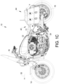
- FIG 8 also illustrates further details of the fender assembly 28.
- the fender assembly 28 may include an outer fender 28A an inner fender 28B and a space for electronics 32 therebetween. The electronics 32 are hidden from view by the fender assembly 28.
- step 214 fastens the driver seat pan 48 to the fender assembly 28 using the fastener 58.
- the fastener 58 holds the first bracket 54B against the fender assembly 28.
- the opening 68 has the grab strap 60 inserted therein. It should be noted that the opening 68 corresponds to the opening 68' within the seat cover 62 and the second seat support 66.
- the first opening 68 is positioned over the fastener 58. That is, the head portion 102 is received within the second opening 70.
- the reinforcement member 72 is used to reinforce the second seat pan and receive the head portion 102 so that the shaft portion 100 is adjacent to the reinforcement member 72.
- the rear of the passenger seat is coupled to the fender assembly 28.
- the fastener 76 is used to retain the second bracket 74 and thus the second seat pan 64 against the fender assembly 28.
- the driver seat 42 may be used alone, which is not part of the invention, and thus the grab strap 60 may be tucked under the first seat pan or removed.
- the second seat pan 64 is coupled to the fender assembly 28 in the front through the fastener 58 and in the back through the fastener 76.
Landscapes
- Engineering & Computer Science (AREA)
- Mechanical Engineering (AREA)
- Seats For Vehicles (AREA)
Claims (15)
- Véhicule (10) comportant un châssis de véhicule (12), un ensemble de garde-boue arrière (28), un ensemble de sièges (40) et un axe longitudinal (30), l'ensemble de sièges (40) comprenant :un plateau de premier siège (48) d'un siège de conducteur (42) qui comporte un premier coupleur (108) qui couple le siège de conducteur (42) sur le châssis de véhicule (12) ;un support de premier siège (50) du siège de conducteur (42) qui est adjacent au plateau de premier siège (48) ;une sangle de préhension (60) qui est couplée sur le plateau de premier siège (48) ;un moyen de recouvrement de premier siège (46) du siège de conducteur (42) qui est couplé sur le plateau de premier siège (48) ;un premier moyen de fixation (58) qui couple le siège de conducteur (42) sur l'ensemble de garde-boue arrière (28) ;un siège de passager (44) qui comporte un moyen de recouvrement de second siège (62), un plateau de second siège (64) et un support de second siège (66) qui est disposé entre le moyen de recouvrement de second siège (62) et le plateau de second siège (64), le plateau de second siège (64) étant couplé sur l'ensemble de garde-boue arrière (28) à l'aide du premier moyen de fixation (58) ; etun second moyen de fixation (80) qui couple le plateau de second siège (64) sur l'ensemble de garde-boue arrière (28) ;caractérisé en ce que ledit plateau de second siège (64) comprend une première ouverture (68), la sangle de préhension (60) étant insérée au travers de la première ouverture (68) qui est ménagée dans le plateau de second siège (64) et au travers du support de second siège (66) et du moyen de recouvrement de second siège (62).
- Véhicule (10) tel que revendiqué selon la revendication 1, dans lequel le premier coupleur (108) comprend une languette (90) qui couple le plateau de premier siège (48) sur le châssis de véhicule (12) ou dans lequel le premier coupleur (108) comprend une première languette et une seconde languette qui couplent le plateau de premier siège (48) sur des côtés respectifs du châssis de véhicule (12).
- Véhicule (10) tel que revendiqué selon la revendication 1, dans lequel l'ensemble de garde-boue arrière (28) comprend une première partie de garde-boue et une seconde partie de garde-boue qui est espacée de la première partie de garde-boue.
- Véhicule (10) tel que revendiqué selon la revendication 1, dans lequel la sangle de préhension (60) est couplée sur une première console (54B), ladite première console (54B) étant couplée sur le plateau de premier siège (48).
- Véhicule (10) tel que revendiqué selon la revendication 4, dans lequel le premier moyen de fixation (58) couple le plateau de premier siège (48) sur l'ensemble de garde-boue arrière (28) par l'intermédiaire de la première console (54B).
- Véhicule (10) tel que revendiqué selon la revendication 4, dans lequel le plateau de second siège (64) comprend une seconde ouverture (70) et dans lequel le premier moyen de fixation (58) comprend une tête (102) qui est étendue depuis la première console (54B), ladite tête (102) étant reçue à l'intérieur de la seconde ouverture (70).
- Véhicule (10) tel que revendiqué selon la revendication 6, comprenant en outre un élément de renforcement (72) qui est disposé à l'intérieur de la seconde ouverture (70), ledit plateau de second siège (64) étant couplé sur le premier moyen de fixation (58) au niveau de l'élément de renforcement (72).
- Véhicule (10) tel que revendiqué selon la revendication 1, comprenant en outre une seconde console (74) qui est couplée sur le plateau de second siège (64), ledit second moyen de fixation (80) couplant la seconde console (74) sur l'ensemble de garde-boue arrière (28).
- Véhicule (10) tel que revendiqué selon la revendication 1, dans lequel le plateau de premier siège (48) comprend une partie de dossier (48B) et le plateau de second siège (64) comprend un évidement (92) qui reçoit partiellement la partie de dossier (48B).
- Procédé d'assemblage de l'ensemble de sièges (40) du véhicule (10) tel que revendiqué selon la revendication 1, comprenant :le couplage d'une partie avant du plateau de premier siège (48) sur le châssis de véhicule (12) ;le couplage de la sangle de préhension (60) sur le plateau de premier siège (48) ;le couplage d'une partie de dossier (48B) du plateau de premier siège (48) sur l'ensemble de garde-boue arrière (28) ;l'insertion de la sangle de préhension (60) au travers de la première ouverture (68) qui est ménagée dans le plateau de second siège (64) et au travers du support de second siège (66) et du moyen de recouvrement de second siège (62) ;le couplage d'une partie avant du plateau de second siège (64) sur l'ensemble de garde-boue arrière (28) ; etle couplage d'une partie arrière du plateau de second siège (64) sur l'ensemble de garde-boue arrière (28).
- Procédé selon la revendication 10, dans lequel le couplage de la partie avant du plateau de premier siège (48) comprend le couplage de languettes (90) du plateau de premier siège (48) à l'intérieur d'un récepteur (104) qui est associé au châssis de véhicule (12).
- Procédé selon la revendication 10, dans lequel le couplage de la sangle de préhension (60) sur le plateau de premier siège (48) comprend le couplage de la sangle de préhension (60) sur le plateau de premier siège (48) à l'aide d'une première console (54B).
- Procédé selon la revendication 12, dans lequel le couplage de la partie de dossier (48B) du plateau de premier siège (48) comprend le couplage de la partie de dossier (48B) du plateau de premier siège (48) sur l'ensemble de garde-boue arrière (28) à l'aide de la première console (54B) et du premier moyen de fixation (58) en couplage au travers.
- Procédé selon la revendication 13, dans lequel le couplage de la partie avant du plateau de second siège (64) comprend le couplage de la partie avant du plateau de second siège (64) sur l'ensemble de garde-boue arrière (28) à l'aide du premier moyen de fixation (58).
- Procédé selon la revendication 13, dans lequel le couplage de la partie avant du plateau de second siège (64) comprend le couplage de la partie avant du plateau de second siège (64) sur l'ensemble de garde-boue arrière (28) à l'aide du premier moyen de fixation (58) en insérant une tête (102) du premier moyen de fixation (58) à l'intérieur d'une seconde ouverture (70) du plateau de second siège (64).
Applications Claiming Priority (2)
| Application Number | Priority Date | Filing Date | Title |
|---|---|---|---|
| US16/781,061 US11077902B1 (en) | 2020-02-04 | 2020-02-04 | Seating assembly in multiple configurations in a two-wheeled vehicle |
| PCT/US2021/015304 WO2021158411A1 (fr) | 2020-02-04 | 2021-01-27 | Ensemble d'assise dans de multiples configurations dans un véhicule à deux roues |
Publications (2)
| Publication Number | Publication Date |
|---|---|
| EP4100305A1 EP4100305A1 (fr) | 2022-12-14 |
| EP4100305B1 true EP4100305B1 (fr) | 2025-07-02 |
Family
ID=74666815
Family Applications (1)
| Application Number | Title | Priority Date | Filing Date |
|---|---|---|---|
| EP21706457.5A Active EP4100305B1 (fr) | 2020-02-04 | 2021-01-27 | Ensemble d'assise dans de multiples configurations dans un véhicule à deux roues |
Country Status (5)
| Country | Link |
|---|---|
| US (1) | US11077902B1 (fr) |
| EP (1) | EP4100305B1 (fr) |
| JP (1) | JP7312333B2 (fr) |
| CN (1) | CN115243966A (fr) |
| WO (1) | WO2021158411A1 (fr) |
Family Cites Families (21)
| Publication number | Priority date | Publication date | Assignee | Title |
|---|---|---|---|---|
| JPS6171582A (ja) | 1984-09-14 | 1986-04-12 | 株式会社東芝 | 誘導加熱調理器 |
| JPH0139670Y2 (fr) * | 1984-10-05 | 1989-11-28 | ||
| JPS6378887A (ja) * | 1986-09-22 | 1988-04-08 | ヤマハ発動機株式会社 | 自動二,三輪車の荷台装置 |
| JP3500906B2 (ja) * | 1997-04-23 | 2004-02-23 | スズキ株式会社 | 自動二輪車のシート取付構造 |
| JP3645410B2 (ja) * | 1997-12-09 | 2005-05-11 | 本田技研工業株式会社 | 自動2輪車のシート及びリヤカウルの一体化構造 |
| US6273207B1 (en) * | 1999-07-29 | 2001-08-14 | Harley-Davidson Motor Company | Motorcycle seat |
| JP2002362449A (ja) * | 2001-06-08 | 2002-12-18 | Yamaha Motor Co Ltd | 自動二輪車のシート取付け構造 |
| JP3789906B2 (ja) * | 2003-05-23 | 2006-06-28 | 株式会社ホンダアクセス | 自動二輪車のサドルバッグ取付装置 |
| US7837260B2 (en) | 2005-05-31 | 2010-11-23 | Milsco Manufacturing Company | Vehicle seat assembly system |
| US8225972B2 (en) * | 2007-06-29 | 2012-07-24 | Harley-Davidson Motor Company Group, Inc. | Luggage rack and passenger seat for a motorcycle |
| US8151925B2 (en) * | 2009-06-04 | 2012-04-10 | Polaris Industries Inc. | Two-wheeled vehicle |
| US8371652B2 (en) * | 2009-11-17 | 2013-02-12 | John R. Revell | Backrest for motorcycles |
| JP5980074B2 (ja) * | 2012-09-28 | 2016-08-31 | 川崎重工業株式会社 | 鞍乗型車両のシート |
| JP5963206B2 (ja) | 2013-08-29 | 2016-08-03 | 本田技研工業株式会社 | 鞍乗り型車両のシート支持構造 |
| JP6333593B2 (ja) * | 2014-03-20 | 2018-05-30 | テイ・エス テック株式会社 | 車両用シート |
| JP6681564B2 (ja) * | 2014-08-05 | 2020-04-15 | テイ・エス テック株式会社 | 自動二輪車のシート装置 |
| JP6417180B2 (ja) * | 2014-10-10 | 2018-10-31 | 川崎重工業株式会社 | 鞍乗型車両のシート構造 |
| US9663168B2 (en) | 2014-10-10 | 2017-05-30 | Kawasaki Jukogyo Kabushiki Kaisha | Straddle-type vehicle and seat structure thereof |
| DE102015105330A1 (de) * | 2015-04-08 | 2016-10-13 | Ujet Vehicles S.À.R.L. | Batteriebaugruppe und Motorroller mit einer Batteriebaugruppe |
| EP3381745B1 (fr) * | 2017-03-29 | 2019-10-09 | TS Tech Co., Ltd. | Siège de transport |
| US11390350B2 (en) * | 2018-08-07 | 2022-07-19 | Harley-Davidson Motor Company Group, LLC | Seat caddy for charging cable |
-
2020
- 2020-02-04 US US16/781,061 patent/US11077902B1/en active Active
-
2021
- 2021-01-27 JP JP2022547702A patent/JP7312333B2/ja active Active
- 2021-01-27 CN CN202180018071.2A patent/CN115243966A/zh active Pending
- 2021-01-27 WO PCT/US2021/015304 patent/WO2021158411A1/fr not_active Ceased
- 2021-01-27 EP EP21706457.5A patent/EP4100305B1/fr active Active
Also Published As
| Publication number | Publication date |
|---|---|
| WO2021158411A1 (fr) | 2021-08-12 |
| US11077902B1 (en) | 2021-08-03 |
| US20210237818A1 (en) | 2021-08-05 |
| CN115243966A (zh) | 2022-10-25 |
| JP2023505609A (ja) | 2023-02-09 |
| EP4100305A1 (fr) | 2022-12-14 |
| JP7312333B2 (ja) | 2023-07-20 |
Similar Documents
| Publication | Publication Date | Title |
|---|---|---|
| US20230406434A1 (en) | Two-wheeled vehicle | |
| US20180216780A1 (en) | Two-wheeled vehicle | |
| JP5694854B2 (ja) | 鞍乗り型車両のハンドルウェイト取り付け構造 | |
| CA2727897C (fr) | Siege de vehicule, siege d'embarcation, procede de fabrication d'un siege de vehicule et procede de fabrication d'un siege d'embarcation | |
| JP6483112B2 (ja) | 二輪自動車 | |
| EP4100305B1 (fr) | Ensemble d'assise dans de multiples configurations dans un véhicule à deux roues | |
| JP7296518B2 (ja) | 鞍乗り型車両 | |
| US20040173047A1 (en) | Steering wheel armature with detachable rim | |
| US10899412B2 (en) | Two wheeled vehicle | |
| JP3470575B2 (ja) | 自動二輪車の収納箱内工具収納装置 | |
| US7686121B2 (en) | All terrain vehicle | |
| US12258087B2 (en) | Saddle-ride vehicle | |
| JP7218395B2 (ja) | 鞍乗り型車両 | |
| JP2630730B2 (ja) | 騎乗型車両のサイドカバーの製造方法 | |
| JP2009161018A (ja) | 鞍乗型車両 | |
| JP6966986B2 (ja) | 鞍乗型車両 | |
| JPS6229273B2 (fr) | ||
| JP4651980B2 (ja) | スプロケット保持部構造 | |
| JP2022083720A (ja) | ピリオンシートの取付構造 | |
| JP2005001512A (ja) | 鞍乗型車両における燃料タンク支持装置 | |
| JP2000053060A (ja) | 車両用操向ハンドル | |
| JP2006182065A (ja) | 鞍乗型車両 | |
| JP2005014675A (ja) | 鞍乗り型車両のステアリングシャフト | |
| JPS62265082A (ja) | 自動二輪車のシ−ト取付け装置 | |
| WO2018179746A1 (fr) | Véhicule du type à selle |
Legal Events
| Date | Code | Title | Description |
|---|---|---|---|
| STAA | Information on the status of an ep patent application or granted ep patent |
Free format text: STATUS: UNKNOWN |
|
| STAA | Information on the status of an ep patent application or granted ep patent |
Free format text: STATUS: THE INTERNATIONAL PUBLICATION HAS BEEN MADE |
|
| PUAI | Public reference made under article 153(3) epc to a published international application that has entered the european phase |
Free format text: ORIGINAL CODE: 0009012 |
|
| STAA | Information on the status of an ep patent application or granted ep patent |
Free format text: STATUS: REQUEST FOR EXAMINATION WAS MADE |
|
| 17P | Request for examination filed |
Effective date: 20220905 |
|
| AK | Designated contracting states |
Kind code of ref document: A1 Designated state(s): AL AT BE BG CH CY CZ DE DK EE ES FI FR GB GR HR HU IE IS IT LI LT LU LV MC MK MT NL NO PL PT RO RS SE SI SK SM TR |
|
| DAV | Request for validation of the european patent (deleted) | ||
| DAX | Request for extension of the european patent (deleted) | ||
| STAA | Information on the status of an ep patent application or granted ep patent |
Free format text: STATUS: EXAMINATION IS IN PROGRESS |
|
| 17Q | First examination report despatched |
Effective date: 20230804 |
|
| GRAP | Despatch of communication of intention to grant a patent |
Free format text: ORIGINAL CODE: EPIDOSNIGR1 |
|
| STAA | Information on the status of an ep patent application or granted ep patent |
Free format text: STATUS: GRANT OF PATENT IS INTENDED |
|
| RIC1 | Information provided on ipc code assigned before grant |
Ipc: B62K 11/04 20060101ALN20250110BHEP Ipc: B62K 19/30 20060101ALI20250110BHEP Ipc: B62J 15/00 20060101ALI20250110BHEP Ipc: B62J 1/14 20060101ALI20250110BHEP Ipc: B62J 1/08 20060101ALI20250110BHEP Ipc: B62J 1/12 20060101ALI20250110BHEP Ipc: B62J 1/28 20060101ALI20250110BHEP Ipc: B62J 25/08 20200101AFI20250110BHEP |
|
| INTG | Intention to grant announced |
Effective date: 20250124 |
|
| GRAS | Grant fee paid |
Free format text: ORIGINAL CODE: EPIDOSNIGR3 |
|
| GRAA | (expected) grant |
Free format text: ORIGINAL CODE: 0009210 |
|
| STAA | Information on the status of an ep patent application or granted ep patent |
Free format text: STATUS: THE PATENT HAS BEEN GRANTED |
|
| AK | Designated contracting states |
Kind code of ref document: B1 Designated state(s): AL AT BE BG CH CY CZ DE DK EE ES FI FR GB GR HR HU IE IS IT LI LT LU LV MC MK MT NL NO PL PT RO RS SE SI SK SM TR |
|
| REG | Reference to a national code |
Ref country code: GB Ref legal event code: FG4D |
|
| REG | Reference to a national code |
Ref country code: CH Ref legal event code: EP |
|
| REG | Reference to a national code |
Ref country code: DE Ref legal event code: R096 Ref document number: 602021033287 Country of ref document: DE |
|
| REG | Reference to a national code |
Ref country code: IE Ref legal event code: FG4D |
|
| REG | Reference to a national code |
Ref country code: NL Ref legal event code: MP Effective date: 20250702 |
|
| PG25 | Lapsed in a contracting state [announced via postgrant information from national office to epo] |
Ref country code: PT Free format text: LAPSE BECAUSE OF FAILURE TO SUBMIT A TRANSLATION OF THE DESCRIPTION OR TO PAY THE FEE WITHIN THE PRESCRIBED TIME-LIMIT Effective date: 20251103 |
|
| PG25 | Lapsed in a contracting state [announced via postgrant information from national office to epo] |
Ref country code: NL Free format text: LAPSE BECAUSE OF FAILURE TO SUBMIT A TRANSLATION OF THE DESCRIPTION OR TO PAY THE FEE WITHIN THE PRESCRIBED TIME-LIMIT Effective date: 20250702 |
|
| REG | Reference to a national code |
Ref country code: AT Ref legal event code: MK05 Ref document number: 1808953 Country of ref document: AT Kind code of ref document: T Effective date: 20250702 |
|
| PG25 | Lapsed in a contracting state [announced via postgrant information from national office to epo] |
Ref country code: IS Free format text: LAPSE BECAUSE OF FAILURE TO SUBMIT A TRANSLATION OF THE DESCRIPTION OR TO PAY THE FEE WITHIN THE PRESCRIBED TIME-LIMIT Effective date: 20251102 |
|
| PG25 | Lapsed in a contracting state [announced via postgrant information from national office to epo] |
Ref country code: NO Free format text: LAPSE BECAUSE OF FAILURE TO SUBMIT A TRANSLATION OF THE DESCRIPTION OR TO PAY THE FEE WITHIN THE PRESCRIBED TIME-LIMIT Effective date: 20251002 |
|
| REG | Reference to a national code |
Ref country code: LT Ref legal event code: MG9D |
|
| PG25 | Lapsed in a contracting state [announced via postgrant information from national office to epo] |
Ref country code: AT Free format text: LAPSE BECAUSE OF FAILURE TO SUBMIT A TRANSLATION OF THE DESCRIPTION OR TO PAY THE FEE WITHIN THE PRESCRIBED TIME-LIMIT Effective date: 20250702 |
|
| PG25 | Lapsed in a contracting state [announced via postgrant information from national office to epo] |
Ref country code: FI Free format text: LAPSE BECAUSE OF FAILURE TO SUBMIT A TRANSLATION OF THE DESCRIPTION OR TO PAY THE FEE WITHIN THE PRESCRIBED TIME-LIMIT Effective date: 20250702 |
|
| PG25 | Lapsed in a contracting state [announced via postgrant information from national office to epo] |
Ref country code: HR Free format text: LAPSE BECAUSE OF FAILURE TO SUBMIT A TRANSLATION OF THE DESCRIPTION OR TO PAY THE FEE WITHIN THE PRESCRIBED TIME-LIMIT Effective date: 20250702 |
|
| PGFP | Annual fee paid to national office [announced via postgrant information from national office to epo] |
Ref country code: FR Payment date: 20251217 Year of fee payment: 6 |
|
| PG25 | Lapsed in a contracting state [announced via postgrant information from national office to epo] |
Ref country code: GR Free format text: LAPSE BECAUSE OF FAILURE TO SUBMIT A TRANSLATION OF THE DESCRIPTION OR TO PAY THE FEE WITHIN THE PRESCRIBED TIME-LIMIT Effective date: 20251003 |
|
| PG25 | Lapsed in a contracting state [announced via postgrant information from national office to epo] |
Ref country code: SE Free format text: LAPSE BECAUSE OF FAILURE TO SUBMIT A TRANSLATION OF THE DESCRIPTION OR TO PAY THE FEE WITHIN THE PRESCRIBED TIME-LIMIT Effective date: 20250702 Ref country code: CZ Free format text: LAPSE BECAUSE OF FAILURE TO SUBMIT A TRANSLATION OF THE DESCRIPTION OR TO PAY THE FEE WITHIN THE PRESCRIBED TIME-LIMIT Effective date: 20250702 |
|
| PG25 | Lapsed in a contracting state [announced via postgrant information from national office to epo] |
Ref country code: LV Free format text: LAPSE BECAUSE OF FAILURE TO SUBMIT A TRANSLATION OF THE DESCRIPTION OR TO PAY THE FEE WITHIN THE PRESCRIBED TIME-LIMIT Effective date: 20250702 |
|
| PG25 | Lapsed in a contracting state [announced via postgrant information from national office to epo] |
Ref country code: BG Free format text: LAPSE BECAUSE OF FAILURE TO SUBMIT A TRANSLATION OF THE DESCRIPTION OR TO PAY THE FEE WITHIN THE PRESCRIBED TIME-LIMIT Effective date: 20250702 Ref country code: PL Free format text: LAPSE BECAUSE OF FAILURE TO SUBMIT A TRANSLATION OF THE DESCRIPTION OR TO PAY THE FEE WITHIN THE PRESCRIBED TIME-LIMIT Effective date: 20250702 |
|
| PG25 | Lapsed in a contracting state [announced via postgrant information from national office to epo] |
Ref country code: RS Free format text: LAPSE BECAUSE OF FAILURE TO SUBMIT A TRANSLATION OF THE DESCRIPTION OR TO PAY THE FEE WITHIN THE PRESCRIBED TIME-LIMIT Effective date: 20251002 |
|
| PG25 | Lapsed in a contracting state [announced via postgrant information from national office to epo] |
Ref country code: ES Free format text: LAPSE BECAUSE OF FAILURE TO SUBMIT A TRANSLATION OF THE DESCRIPTION OR TO PAY THE FEE WITHIN THE PRESCRIBED TIME-LIMIT Effective date: 20250702 |