EP4100305B1 - Seating assembly in multiple configurations in a two-wheeled vehicle - Google Patents
Seating assembly in multiple configurations in a two-wheeled vehicle Download PDFInfo
- Publication number
- EP4100305B1 EP4100305B1 EP21706457.5A EP21706457A EP4100305B1 EP 4100305 B1 EP4100305 B1 EP 4100305B1 EP 21706457 A EP21706457 A EP 21706457A EP 4100305 B1 EP4100305 B1 EP 4100305B1
- Authority
- EP
- European Patent Office
- Prior art keywords
- seat
- seat pan
- coupling
- vehicle
- pan
- Prior art date
- Legal status (The legal status is an assumption and is not a legal conclusion. Google has not performed a legal analysis and makes no representation as to the accuracy of the status listed.)
- Active
Links
Images


Classifications
-
- B—PERFORMING OPERATIONS; TRANSPORTING
- B62—LAND VEHICLES FOR TRAVELLING OTHERWISE THAN ON RAILS
- B62J—CYCLE SADDLES OR SEATS; AUXILIARY DEVICES OR ACCESSORIES SPECIALLY ADAPTED TO CYCLES AND NOT OTHERWISE PROVIDED FOR, e.g. ARTICLE CARRIERS OR CYCLE PROTECTORS
- B62J1/00—Saddles or other seats for cycles; Arrangement thereof; Component parts
- B62J1/12—Box-shaped seats; Bench-type seats, e.g. dual or twin seats
-
- B—PERFORMING OPERATIONS; TRANSPORTING
- B62—LAND VEHICLES FOR TRAVELLING OTHERWISE THAN ON RAILS
- B62J—CYCLE SADDLES OR SEATS; AUXILIARY DEVICES OR ACCESSORIES SPECIALLY ADAPTED TO CYCLES AND NOT OTHERWISE PROVIDED FOR, e.g. ARTICLE CARRIERS OR CYCLE PROTECTORS
- B62J1/00—Saddles or other seats for cycles; Arrangement thereof; Component parts
- B62J1/08—Frames for saddles; Connections between saddle frames and seat pillars; Seat pillars
-
- B—PERFORMING OPERATIONS; TRANSPORTING
- B62—LAND VEHICLES FOR TRAVELLING OTHERWISE THAN ON RAILS
- B62J—CYCLE SADDLES OR SEATS; AUXILIARY DEVICES OR ACCESSORIES SPECIALLY ADAPTED TO CYCLES AND NOT OTHERWISE PROVIDED FOR, e.g. ARTICLE CARRIERS OR CYCLE PROTECTORS
- B62J1/00—Saddles or other seats for cycles; Arrangement thereof; Component parts
- B62J1/14—Separate pillions
-
- B—PERFORMING OPERATIONS; TRANSPORTING
- B62—LAND VEHICLES FOR TRAVELLING OTHERWISE THAN ON RAILS
- B62J—CYCLE SADDLES OR SEATS; AUXILIARY DEVICES OR ACCESSORIES SPECIALLY ADAPTED TO CYCLES AND NOT OTHERWISE PROVIDED FOR, e.g. ARTICLE CARRIERS OR CYCLE PROTECTORS
- B62J1/00—Saddles or other seats for cycles; Arrangement thereof; Component parts
- B62J1/18—Covers for saddles or other seats; Paddings
-
- B—PERFORMING OPERATIONS; TRANSPORTING
- B62—LAND VEHICLES FOR TRAVELLING OTHERWISE THAN ON RAILS
- B62J—CYCLE SADDLES OR SEATS; AUXILIARY DEVICES OR ACCESSORIES SPECIALLY ADAPTED TO CYCLES AND NOT OTHERWISE PROVIDED FOR, e.g. ARTICLE CARRIERS OR CYCLE PROTECTORS
- B62J1/00—Saddles or other seats for cycles; Arrangement thereof; Component parts
- B62J1/28—Other additional equipment, e.g. back-rests for children
-
- B—PERFORMING OPERATIONS; TRANSPORTING
- B62—LAND VEHICLES FOR TRAVELLING OTHERWISE THAN ON RAILS
- B62J—CYCLE SADDLES OR SEATS; AUXILIARY DEVICES OR ACCESSORIES SPECIALLY ADAPTED TO CYCLES AND NOT OTHERWISE PROVIDED FOR, e.g. ARTICLE CARRIERS OR CYCLE PROTECTORS
- B62J15/00—Mud-guards for wheels
-
- B—PERFORMING OPERATIONS; TRANSPORTING
- B62—LAND VEHICLES FOR TRAVELLING OTHERWISE THAN ON RAILS
- B62J—CYCLE SADDLES OR SEATS; AUXILIARY DEVICES OR ACCESSORIES SPECIALLY ADAPTED TO CYCLES AND NOT OTHERWISE PROVIDED FOR, e.g. ARTICLE CARRIERS OR CYCLE PROTECTORS
- B62J25/00—Foot-rests; Knee grips; Passenger hand-grips
- B62J25/08—Passengers hand-grips
-
- B—PERFORMING OPERATIONS; TRANSPORTING
- B62—LAND VEHICLES FOR TRAVELLING OTHERWISE THAN ON RAILS
- B62K—CYCLES; CYCLE FRAMES; CYCLE STEERING DEVICES; RIDER-OPERATED TERMINAL CONTROLS SPECIALLY ADAPTED FOR CYCLES; CYCLE AXLE SUSPENSIONS; CYCLE SIDE-CARS, FORECARS, OR THE LIKE
- B62K19/00—Cycle frames
- B62K19/30—Frame parts shaped to receive other cycle parts or accessories
-
- B—PERFORMING OPERATIONS; TRANSPORTING
- B62—LAND VEHICLES FOR TRAVELLING OTHERWISE THAN ON RAILS
- B62K—CYCLES; CYCLE FRAMES; CYCLE STEERING DEVICES; RIDER-OPERATED TERMINAL CONTROLS SPECIALLY ADAPTED FOR CYCLES; CYCLE AXLE SUSPENSIONS; CYCLE SIDE-CARS, FORECARS, OR THE LIKE
- B62K11/00—Motorcycles, engine-assisted cycles or motor scooters with one or two wheels
- B62K11/02—Frames
- B62K11/04—Frames characterised by the engine being between front and rear wheels
Definitions
- the frame 12 is also used to support a seat assembly 40.
- the seat assembly 40 includes a driver seat 42 and a passenger seat 44.
- the driver seat 42 and the passenger seat 44 are assembled to form the seat assembly 40.
- the driver seat 42 may be used without the passenger seat 44 in embodiments not being part of the invention.
- the passenger seat 44 is higher (relative to the road during driving) than the driver seat 42.
- a first seat cover 46 is the outer surface of the driver seat 42.
- the seat cover 46 may be made of various materials including but not limited to cloth, leather, plastics or vinyl.
- the first seat cover 46 is secured to the first seat pan 48.
- the seat pan 48 has a bottom portion 48A and a back portion 48B.
- the shape of the seat pan 48 ultimately determines the space of the seat position.
- the first seat pan 48 may take many shapes.
- a first seat support 50 is disposed between the first seat cover 46 and the first seat pan 48.
- the first seat support 50 may be a cushion formed of a foam material.
- the first seat support 50 is used to support the body of the driver.
- the first seat support 50 may having heating and cooling disposed therein.
- the first bracket 54A is used when the driver seat 42 is to be used alone, which is not part of the invention.
- an alternate first bracket 54B is used.
- the first bracket 54A is removed and bracket 54B is secured with the fasteners 56 to the same position in the first seat pan 48.
- a grab strap 60 is coupled to the first bracket 54B at grab strap slots 61 set forth below.
- the grab strap 60 may be made of various materials and allows a passenger to grip thereto.
- a second bracket 74 is secured to the second seat pan 64 with one or more fasteners 76.
- the fasteners 76 may, for example, be screws.
- the second seat pan 64 may also include feet 78 formed in a similar manner to that set forth above. The feet 78 are used to space the seat pan 64 from the fender assembly 28.
- a fastener 80 is used to couple the second bracket 74 and thus the second seat pan 64 to the fender assembly 28.
- the tabs 90 illustrated above are inserted within receivers 104 of the frame 12.
- the receiver 104 may be disposed directly on the frame or in a bracket 106 coupled to the frame 12.
- the tabs 90 and the receivers 104 may be referred to as a coupler 108 for coupling the seat pan 48 to the frame.
- the receiver 104 comprises a pair of slots disposed on either side of the vehicle 10.
- the receiver 104 receive the tabs 90 with a forward motion of the first seat pan 48.
- the tabs 90 are inserted into the receiver 104 in a forward direction.
- FIG 8 also illustrates further details of the fender assembly 28.
- the fender assembly 28 may include an outer fender 28A an inner fender 28B and a space for electronics 32 therebetween. The electronics 32 are hidden from view by the fender assembly 28.
- step 214 fastens the driver seat pan 48 to the fender assembly 28 using the fastener 58.
- the fastener 58 holds the first bracket 54B against the fender assembly 28.
- the opening 68 has the grab strap 60 inserted therein. It should be noted that the opening 68 corresponds to the opening 68' within the seat cover 62 and the second seat support 66.
- the first opening 68 is positioned over the fastener 58. That is, the head portion 102 is received within the second opening 70.
- the reinforcement member 72 is used to reinforce the second seat pan and receive the head portion 102 so that the shaft portion 100 is adjacent to the reinforcement member 72.
- the rear of the passenger seat is coupled to the fender assembly 28.
- the fastener 76 is used to retain the second bracket 74 and thus the second seat pan 64 against the fender assembly 28.
- the driver seat 42 may be used alone, which is not part of the invention, and thus the grab strap 60 may be tucked under the first seat pan or removed.
- the second seat pan 64 is coupled to the fender assembly 28 in the front through the fastener 58 and in the back through the fastener 76.
Landscapes
- Engineering & Computer Science (AREA)
- Mechanical Engineering (AREA)
- Seats For Vehicles (AREA)
Description
- The present disclosure relates to a vehicle and a method of assembling a seat assembly of the vehicle.
- This section provides background information related to the present disclosure which is not necessarily prior art.
- Providing a comfortable seat that is easy to assemble for a vehicle has been a goal for vehicle providers for years. Motorcycle manufacturers often use a common frame for various models with various options. Seating arrangements can vary in the various model. One and two seat configurations are possible. To seat arrangements that allow the customer to make the change are also possible. However, providing a convenient configuration for making the change is important. A vehicle according to the preamble of claim 1 is disclosed in
JP S61 71582 U - The invention is defined in
independent claims 1 and 10. Preferred embodiments of the invention are provided in the dependent claims. - The present disclosure provides an improved seating configuration that allows easy assembly and reconfiguration from one to two seating positions. While the system is suitable for various types of automotive vehicles, the configuration set forth herein provides a configuration particularly suitable for motorcycles and open air vehicles.
- Further areas of applicability will become apparent from the description provided herein. The description and specific examples in this summary are intended for purposes of illustration only and are not intended to limit the scope of the present disclosure.
- The drawings described herein are for illustrative purposes only of selected embodiments and not all possible implementations, and are not intended to limit the scope of the present disclosure.
-
Fig. 1A is a perspective view of a motorcycle having a seat assembly according to the present disclosure; -
Fig. 1B is a right side view of the motorcycle ofFig. 1A ; -
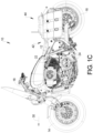
Fig. 1C is a left side view of the motorcycle ofFig. 1A . -
Fig. 2A is an exploded view of the front seat assembly; -
Fig. 2B is an exploded view of the rear seat assembly. -
Fig. 3A is a perspective view of seat pans of the seat assembly ofFig. 1A . -
Fig. 3B is an underside view of seat pans of the seat. -
Fig. 4 is an underside view of the first seat pan; -
Fig. 5 is a cross-sectional view of the passenger seat coupled to the driver seat; -
Fig. 6 is a perspective view of the first fastener; -
Fig. 7 is a perspective view of the seat back portion of the driver's seat; -
Fig. 8 is a side view of the first seat pan being assembled to the frame; -
Fig. 9 is a perspective view of the passenger seat being assembly to the vehicle; -
Fig. 10 is a partial perspective view of the passenger seat coupled to the fender; -
Fig. 11 is a flow chart of a method for assembling the seat. - Corresponding reference numerals indicate corresponding parts throughout the various views of the drawings.
- Example embodiments will now be described more fully with reference to the accompanying drawings. Although the following description includes a motorcycle application, it is understood that the features herein may be applied to any appropriate vehicle, such as snowmobiles, all-terrain vehicles, utility vehicles, moped and scooters. The embodiments disclosed below are not intended to be exhaustive or to limit the invention to the precise forms disclosed in the following detailed description. Rather, the embodiments are chosen and described so that others skilled in the art may utilize their teachings.
- The relative terms used in the present disclosure are relative to a
vehicle 10 in a normal operating position. The vehicle direction inFigures 1A-1C with a longitudinal axis that corresponds to a normal direction of travel. Right, left, front, back, under and above all referred to relative position of the vehicle in a normal upright position on a road surface. - Referring now to
Figures 1A-1C , avehicle 10 is illustrated. Thevehicle 10 in this example is a two-wheeled vehicle. The two-wheeled vehicle 10 illustrated is a touring style motorcycle. However, the present example is also applicable to other types of vehicles including snowmobiles, scooters, utility vehicles, and off-road vehicles that accommodate passengers in a one of many seating positions - The
vehicle 10 includes aframe 12 that is used to support the vehiclecomponents including wheels Wheel 14 is a front wheel which is coupled to thehandlebars 18 by way of a first fork for steering. Therear wheel 16 is a coupled to apowertrain assembly 20 that is used to provide the rotational force to therear wheel 16, in this example. Of course, all of the wheels on a vehicle or a selected few of the wheels may be coupled to thepowertrain assembly 20. Thepowertrain assembly 20 includes anengine 22 andtransmission 24. Thepowertrain assembly 20 may also include anexhaust pipe 26 that removes waste exhaust from theengine 22. - A
rear fender assembly 28 is disposed above therear wheel 16. Therear fender assembly 28 is secured to theframe 12. - The
vehicle 10 also has alongitudinal axis 30 that extends in the direction of forward travel of thevehicle 10 that extends from thefront wheel 14 to therear wheel 16. - The
frame 12 is also used to support aseat assembly 40. Theseat assembly 40 includes adriver seat 42 and apassenger seat 44. In this example, thedriver seat 42 and thepassenger seat 44 are assembled to form theseat assembly 40. However thedriver seat 42 may be used without thepassenger seat 44 in embodiments not being part of the invention. Thepassenger seat 44 is higher (relative to the road during driving) than thedriver seat 42. - Referring now additionally to
Figures 2A , an exploded view of thedriver seat 42 of theseat assembly 40 is set forth. Afirst seat cover 46 is the outer surface of thedriver seat 42. Theseat cover 46 may be made of various materials including but not limited to cloth, leather, plastics or vinyl. Thefirst seat cover 46 is secured to thefirst seat pan 48. Theseat pan 48 has abottom portion 48A and aback portion 48B. The shape of theseat pan 48 ultimately determines the space of the seat position. Depending on the vehicle and the desired styling of the vehicle, thefirst seat pan 48 may take many shapes. Afirst seat support 50 is disposed between thefirst seat cover 46 and thefirst seat pan 48. By way of example, thefirst seat support 50 may be a cushion formed of a foam material. Thefirst seat support 50 is used to support the body of the driver. Of course, thefirst seat support 50 may having heating and cooling disposed therein. - The
driver seat 42 may also include a plurality offeet 52. Thefeet 52 are secured to the bottom of thefirst seat pan 48 to provide isolation between the frame or fender and thefirst seat pan 48. Thefeet 52 may be formed of various types of materials including, but not limited to, foam, felt, rubber, plastic or nylon. Afirst bracket 54B is secured to theback portion 48B of thefirst seat pan 48. One ormore fasteners 56 may secure the first bracket to thefirst seat pan 48. Afastener 58 may couple the first bracket 54A and thus thefirst seat pan 48 to thefender assembly 28 as will be described in more detail below. The first bracket 54A is used to secure only thefirst seat pan 48 to thefender assembly 28. - The first bracket 54A is used when the
driver seat 42 is to be used alone, which is not part of the invention. When - as according to the invention - thepassenger seat 44 is to be used, an alternatefirst bracket 54B is used. To switch from one configuration to the other thefasteners 56 are removed. The first bracket 54A is removed andbracket 54B is secured with thefasteners 56 to the same position in thefirst seat pan 48. Agrab strap 60 is coupled to thefirst bracket 54B at grab strap slots 61 set forth below. Various ways for coupling thegrab strap 60 to thefirst bracket 54B may be used. Thegrab strap 60 may be made of various materials and allows a passenger to grip thereto. - Referring now to
Figure 2B , thepassenger seat 44 has asecond seat cover 62, asecond seat pan 64 and asecond seat support 66 disposed between thesecond seat cover 62 and thesecond seat pan 64. Thesecond seat pan 64 has afirst opening 68 used to receive thegrab strap 60 during assembly. Asecond opening 70 is used to receive thefastener 58 as will be described in more detail below. Thesecond opening 70 has areinforcement member 72 disposed therein. Thereinforcement member 72 is used to receive the fastener 58 (or afastener head 102 set forth below) during assembly. - A
second bracket 74 is secured to thesecond seat pan 64 with one ormore fasteners 76. Thefasteners 76 may, for example, be screws. Thesecond seat pan 64 may also includefeet 78 formed in a similar manner to that set forth above. Thefeet 78 are used to space theseat pan 64 from thefender assembly 28. Afastener 80 is used to couple thesecond bracket 74 and thus thesecond seat pan 64 to thefender assembly 28. - Referring now to
Figures 3A and 3B , thefirst seat pan 48 is illustrated relative to thesecond seat pan 64. When thedriver seat 42 is coupled to thepassenger seat 44, thesecond seat pan 64 has theback portion 48B partially received therein. - Referring now to
Figure 4 , the underside of thesecond seat pan 64 is illustrated in further detail. Arecess 92 in the second seat pan is used to receive at least a portion of the rear of the first seat pan. Thefirst bracket 54B which is coupled to thefirst seat pan 48 is illustrated. Also, thefastener 58 is also illustrated. - Referring now to
Figure 5 , a cross-sectional view of thefirst seat pan 48 within the recess of thesecond seat pan 64 is set forth. In this example, areceiver 94 receives thefastener 58. Thefastener 58 is secured within thereceiver 94 by a press fit or threading. When thefastener 58 is inserted within thereceiver 94, thefirst bracket 54B is held toward thefender assembly 28. Thereinforcement member 72 is illustrated around the thickness of thesecond seat pan 64 to reinforce thesecond opening 70. - Referring now to
Figure 6 , thefastener 58 is illustrated in further detail. Thefastener 58 has abottom portion 96 that may be threaded. Aflange portion 98 is adjacent to thebottom portion 96. Ashaft portion 100 is directly adjacent to theflange portion 98. Theshaft portion 100 has ahead portion 102. Thehead portion 102 has a greater diameter than theshaft portion 100. Thehead portion 102 may be used to provide an interference fit so that theshaft portion 100 is directly adjacent to thereinforcement member 72 after assembly. Thewider head portion 102 retains thesecond seat pan 64 to thefender assembly 28. Theflange 98 provides an increased area over which to provide a force on thefirst bracket 54B to urge thefirst bracket 54B towards thefender assembly 28. Thesecond seat pan 64 and/or thereinforcement member 72 may be slightly conformable to receive thehead 102 but still retain thefastener 58 in position during operation. - Referring now to
Figures 7-11 , a method for assembling theseat assembly 40 is set forth. Specifically, instep 210, thegrab strap 60 is coupled to thedriver seat 42. In particular, thegrab strap 60 may be looped through thefirst bracket 54B. Thefirst bracket 54B is assembled to thefirst seat pan 48 using thefasteners 56. This is illustrated inFigure 7 . - Referring now specifically to
Figure 8 andFigure 11 , instep 212, thetabs 90 illustrated above are inserted withinreceivers 104 of theframe 12. Thereceiver 104 may be disposed directly on the frame or in abracket 106 coupled to theframe 12. Thetabs 90 and thereceivers 104 may be referred to as acoupler 108 for coupling theseat pan 48 to the frame. In this example, thereceiver 104 comprises a pair of slots disposed on either side of thevehicle 10. Thereceiver 104 receive thetabs 90 with a forward motion of thefirst seat pan 48. In this example, thetabs 90 are inserted into thereceiver 104 in a forward direction. -
Figure 8 also illustrates further details of thefender assembly 28. Thefender assembly 28 may include anouter fender 28A aninner fender 28B and a space forelectronics 32 therebetween. Theelectronics 32 are hidden from view by thefender assembly 28. - Referring now to
Figures 9 and11 ,step 214 fastens thedriver seat pan 48 to thefender assembly 28 using thefastener 58. Thefastener 58 holds thefirst bracket 54B against thefender assembly 28. Theopening 68 has thegrab strap 60 inserted therein. It should be noted that theopening 68 corresponds to the opening 68' within theseat cover 62 and thesecond seat support 66. InFigure 9 , thefirst opening 68 is positioned over thefastener 58. That is, thehead portion 102 is received within thesecond opening 70. Thereinforcement member 72 is used to reinforce the second seat pan and receive thehead portion 102 so that theshaft portion 100 is adjacent to thereinforcement member 72. - Referring now to
Figures 10 and11 , the rear of the passenger seat is coupled to thefender assembly 28. Thefastener 76 is used to retain thesecond bracket 74 and thus thesecond seat pan 64 against thefender assembly 28. - In operation, the
driver seat 42 may be used alone, which is not part of the invention, and thus thegrab strap 60 may be tucked under the first seat pan or removed. When a second orpassenger seat 44 is desired - as in accordance with the invention -, thesecond seat pan 64 is coupled to thefender assembly 28 in the front through thefastener 58 and in the back through thefastener 76. - Examples are provided so that this disclosure will be thorough, and will fully convey the scope of the appended claims to those who are skilled in the art. Numerous specific details are set forth such as examples of specific components, devices, and methods, to provide a thorough understanding of examples of the present disclosure. It will be apparent to those skilled in the art that specific details need not be employed, that examples may be embodied in many different forms and that neither should be construed to limit the scope of the appended claims. In some examples, well-known processes, well-known device structures, and well-known technologies are not described in detail.
- The foregoing description of the examples has been provided for purposes of illustration and description. It is not intended to be exhaustive or to limit the scope of the appended claims. Individual elements or features of a particular example generally not limited to that particular example, but, where applicable, are interchangeable and can be used in a selected embodiment, even if not specifically shown or described. The same may also be varied in many ways. Such variations are not to be regarded as a departure from the scope of the appended claims, and all such modifications are intended to be included within the scope of the appended claims.
Claims (15)
- A vehicle (10) having a vehicle frame (12), a rear fender assembly (28), a seat assembly (40) and a longitudinal axis (30), the seat assembly (40) comprising:a first seat pan (48) of a driver seat (42) having a first coupler (108) coupling the driver seat (42) to the vehicle frame (12);a first seat support (50) of the driver seat (42) adjacent to the first seat pan (48);a grab strap (60) coupled to the first seat pan (48);a first seat cover (46) of the driver seat (42) coupled to the first seat pan (48);a first fastener (58) coupling the driver seat (42) to the rear fender assembly (28);a passenger seat (44) having a second seat cover (62), a second seat pan (64) and a second seat support (66) disposed between the second seat cover (62) and the second seat pan (64), the second seat pan (64) being coupled to the rear fender assembly (28) with the first fastener (58), anda second fastener (80) coupling the second seat pan (64) to the rear fender assembly (28);characterized by said second seat pan (64) comprising a first opening (68), the grab strap (60) being inserted through the first opening (68) in the second seat pan (64) and through the second seat support (66) and the second seat cover (62).
- The vehicle (10) as recited in claim 1 wherein the first coupler (108) comprises a tab (90) coupling the first seat pan (48) to the vehicle frame (12), or wherein the first coupler (108) comprises a first tab and a second tab coupling the first seat pan (48) to respective sides of the vehicle frame (12).
- The vehicle (10) recited in claim 1 wherein the rear fender assembly (28) comprises a first fender portion and a second fender portion spaced apart from the first fender portion.
- The vehicle (10) as recited in claim 1 wherein the grab strap (60) is coupled to a first bracket (54B), said first bracket (54B) being coupled to the first seat pan (48).
- The vehicle (10) as recited in claim 4 wherein the first fastener (58) couples the first seat pan (48) to the rear fender assembly (28) through the first bracket (54B).
- The vehicle (10) as recited in claim 4 wherein the second seat pan (64) comprises a second opening (70) and wherein the first fastener (58) comprises a head (102) extending from the first bracket (54B), said head (102) being received in the second opening (70).
- The vehicle (10) as recited in claim 6 further comprising a reinforcement member (72) disposed within the second opening (70), said second seat pan (64) being coupled to the first fastener (58) at the reinforcement member (72).
- The vehicle (10) as recited in claim 1 further comprising a second bracket (74) coupled to the second seat pan (64), said second fastener (80) coupling the second bracket (74) to the rear fender assembly (28).
- The vehicle (10) as recited in claim 1 wherein the first seat pan (48) comprises a back portion (48B) and the second seat pan (64) comprises a recess (92) partially receiving the back portion (48B).
- A method of assembling the seat assembly (40) of the vehicle (10) as recited in claim 1 comprising:coupling a front portion of the first seat pan (48) to the vehicle frame (12);coupling the grab strap (60) to the first seat pan (48);coupling a back portion (48B) of the first seat pan (48) to the rear fender assembly (28);inserting the grab strap (60) through the first opening (68) in the second seat pan (64) and through the second seat support (66) and the second seat cover (62);coupling a front portion of the second seat pan (64) to the rear fender assembly (28); andcoupling a rear portion of the second seat pan (64) to the rear fender assembly (28).
- The method of claim 10 wherein coupling the front portion of the first seat pan (48) comprises coupling tabs (90) of the first seat pan (48) into a receiver (104) associated with the vehicle frame (12).
- The method of claim 10 wherein coupling the grab strap (60) to the first seat pan (48) comprises coupling the grab strap (60) to the first seat pan (48) with a first bracket (54B).
- The method of claim 12 wherein coupling the back portion (48B) of the first seat pan (48) comprises coupling the back portion (48B) of the first seat pan (48) to the rear fender assembly (28) with the first bracket (54B) and the first fastener (58) coupled therethrough.
- The method of claim 13 wherein coupling the front portion of the second seat pan (64) comprises coupling the front portion of the second seat pan (64) to the rear fender assembly (28) with the first fastener (58).
- The method of claim 13 wherein coupling the front portion of the second seat pan (64) comprises coupling the front portion of the second seat pan (64) to the rear fender assembly (28) with the first fastener (58) by inserting a head (102) of the first fastener (58) into a second opening (70) of the second seat pan (64).
Applications Claiming Priority (2)
| Application Number | Priority Date | Filing Date | Title |
|---|---|---|---|
| US16/781,061 US11077902B1 (en) | 2020-02-04 | 2020-02-04 | Seating assembly in multiple configurations in a two-wheeled vehicle |
| PCT/US2021/015304 WO2021158411A1 (en) | 2020-02-04 | 2021-01-27 | Seating assembly in multiple configurations in a two-wheeled vehicle |
Publications (2)
| Publication Number | Publication Date |
|---|---|
| EP4100305A1 EP4100305A1 (en) | 2022-12-14 |
| EP4100305B1 true EP4100305B1 (en) | 2025-07-02 |
Family
ID=74666815
Family Applications (1)
| Application Number | Title | Priority Date | Filing Date |
|---|---|---|---|
| EP21706457.5A Active EP4100305B1 (en) | 2020-02-04 | 2021-01-27 | Seating assembly in multiple configurations in a two-wheeled vehicle |
Country Status (5)
| Country | Link |
|---|---|
| US (1) | US11077902B1 (en) |
| EP (1) | EP4100305B1 (en) |
| JP (1) | JP7312333B2 (en) |
| CN (1) | CN115243966A (en) |
| WO (1) | WO2021158411A1 (en) |
Family Cites Families (21)
| Publication number | Priority date | Publication date | Assignee | Title |
|---|---|---|---|---|
| JPS6171582A (en) | 1984-09-14 | 1986-04-12 | 株式会社東芝 | Induction heating cooking device |
| JPH0139670Y2 (en) * | 1984-10-05 | 1989-11-28 | ||
| JPS6378887A (en) * | 1986-09-22 | 1988-04-08 | ヤマハ発動機株式会社 | Load-carrying platform for motor bi- and tri-cycle |
| JP3500906B2 (en) * | 1997-04-23 | 2004-02-23 | スズキ株式会社 | Motorcycle seat mounting structure |
| JP3645410B2 (en) * | 1997-12-09 | 2005-05-11 | 本田技研工業株式会社 | Integrated structure of motorcycle seat and rear cowl |
| US6273207B1 (en) * | 1999-07-29 | 2001-08-14 | Harley-Davidson Motor Company | Motorcycle seat |
| JP2002362449A (en) * | 2001-06-08 | 2002-12-18 | Yamaha Motor Co Ltd | Motorcycle seat mounting structure |
| JP3789906B2 (en) * | 2003-05-23 | 2006-06-28 | 株式会社ホンダアクセス | Saddle bag mounting device for motorcycle |
| US7837260B2 (en) | 2005-05-31 | 2010-11-23 | Milsco Manufacturing Company | Vehicle seat assembly system |
| US8225972B2 (en) * | 2007-06-29 | 2012-07-24 | Harley-Davidson Motor Company Group, Inc. | Luggage rack and passenger seat for a motorcycle |
| US8151925B2 (en) * | 2009-06-04 | 2012-04-10 | Polaris Industries Inc. | Two-wheeled vehicle |
| US8371652B2 (en) * | 2009-11-17 | 2013-02-12 | John R. Revell | Backrest for motorcycles |
| JP5980074B2 (en) * | 2012-09-28 | 2016-08-31 | 川崎重工業株式会社 | Saddle type vehicle seat |
| JP5963206B2 (en) | 2013-08-29 | 2016-08-03 | 本田技研工業株式会社 | Seat support structure for saddle-ride type vehicles |
| JP6333593B2 (en) * | 2014-03-20 | 2018-05-30 | テイ・エス テック株式会社 | Vehicle seat |
| JP6681564B2 (en) * | 2014-08-05 | 2020-04-15 | テイ・エス テック株式会社 | Motorcycle seat device |
| JP6417180B2 (en) * | 2014-10-10 | 2018-10-31 | 川崎重工業株式会社 | Seat structure of saddle riding type vehicle |
| US9663168B2 (en) | 2014-10-10 | 2017-05-30 | Kawasaki Jukogyo Kabushiki Kaisha | Straddle-type vehicle and seat structure thereof |
| DE102015105330A1 (en) * | 2015-04-08 | 2016-10-13 | Ujet Vehicles S.À.R.L. | Battery assembly and scooter with a battery assembly |
| EP3381745B1 (en) * | 2017-03-29 | 2019-10-09 | TS Tech Co., Ltd. | Conveyance seat |
| US11390350B2 (en) * | 2018-08-07 | 2022-07-19 | Harley-Davidson Motor Company Group, LLC | Seat caddy for charging cable |
-
2020
- 2020-02-04 US US16/781,061 patent/US11077902B1/en active Active
-
2021
- 2021-01-27 JP JP2022547702A patent/JP7312333B2/en active Active
- 2021-01-27 CN CN202180018071.2A patent/CN115243966A/en active Pending
- 2021-01-27 WO PCT/US2021/015304 patent/WO2021158411A1/en not_active Ceased
- 2021-01-27 EP EP21706457.5A patent/EP4100305B1/en active Active
Also Published As
| Publication number | Publication date |
|---|---|
| WO2021158411A1 (en) | 2021-08-12 |
| US11077902B1 (en) | 2021-08-03 |
| US20210237818A1 (en) | 2021-08-05 |
| CN115243966A (en) | 2022-10-25 |
| JP2023505609A (en) | 2023-02-09 |
| EP4100305A1 (en) | 2022-12-14 |
| JP7312333B2 (en) | 2023-07-20 |
Similar Documents
| Publication | Publication Date | Title |
|---|---|---|
| US20230406434A1 (en) | Two-wheeled vehicle | |
| US20180216780A1 (en) | Two-wheeled vehicle | |
| JP5694854B2 (en) | Handle weight mounting structure for saddle-ride type vehicles | |
| CA2727897C (en) | Vehicular seat, watercraft seat, method for making vehicular seat, and method for making watercraft seat | |
| JP6483112B2 (en) | Motorcycle | |
| EP4100305B1 (en) | Seating assembly in multiple configurations in a two-wheeled vehicle | |
| JP7296518B2 (en) | saddle-riding vehicle | |
| US20040173047A1 (en) | Steering wheel armature with detachable rim | |
| US10899412B2 (en) | Two wheeled vehicle | |
| JP3470575B2 (en) | Tool storage device in motorcycle storage box | |
| US7686121B2 (en) | All terrain vehicle | |
| US12258087B2 (en) | Saddle-ride vehicle | |
| JP7218395B2 (en) | saddle-riding vehicle | |
| JP2630730B2 (en) | Method of manufacturing side cover for riding type vehicle | |
| JP2009161018A (en) | Saddle riding vehicle | |
| JP6966986B2 (en) | Saddle-type vehicle | |
| JPS6229273B2 (en) | ||
| JP4651980B2 (en) | Sprocket holder structure | |
| JP2022083720A (en) | Pillion seat mounting structure | |
| JP2005001512A (en) | Fuel tank support device for saddle riding type vehicle | |
| JP2000053060A (en) | Steering handle for vehicle | |
| JP2006182065A (en) | Saddle ride type vehicle | |
| JP2005014675A (en) | Steering shaft for saddle-ride type vehicles | |
| JPS62265082A (en) | Seat fixture for motorcycle | |
| WO2018179746A1 (en) | Saddle-type vehicle |
Legal Events
| Date | Code | Title | Description |
|---|---|---|---|
| STAA | Information on the status of an ep patent application or granted ep patent |
Free format text: STATUS: UNKNOWN |
|
| STAA | Information on the status of an ep patent application or granted ep patent |
Free format text: STATUS: THE INTERNATIONAL PUBLICATION HAS BEEN MADE |
|
| PUAI | Public reference made under article 153(3) epc to a published international application that has entered the european phase |
Free format text: ORIGINAL CODE: 0009012 |
|
| STAA | Information on the status of an ep patent application or granted ep patent |
Free format text: STATUS: REQUEST FOR EXAMINATION WAS MADE |
|
| 17P | Request for examination filed |
Effective date: 20220905 |
|
| AK | Designated contracting states |
Kind code of ref document: A1 Designated state(s): AL AT BE BG CH CY CZ DE DK EE ES FI FR GB GR HR HU IE IS IT LI LT LU LV MC MK MT NL NO PL PT RO RS SE SI SK SM TR |
|
| DAV | Request for validation of the european patent (deleted) | ||
| DAX | Request for extension of the european patent (deleted) | ||
| STAA | Information on the status of an ep patent application or granted ep patent |
Free format text: STATUS: EXAMINATION IS IN PROGRESS |
|
| 17Q | First examination report despatched |
Effective date: 20230804 |
|
| GRAP | Despatch of communication of intention to grant a patent |
Free format text: ORIGINAL CODE: EPIDOSNIGR1 |
|
| STAA | Information on the status of an ep patent application or granted ep patent |
Free format text: STATUS: GRANT OF PATENT IS INTENDED |
|
| RIC1 | Information provided on ipc code assigned before grant |
Ipc: B62K 11/04 20060101ALN20250110BHEP Ipc: B62K 19/30 20060101ALI20250110BHEP Ipc: B62J 15/00 20060101ALI20250110BHEP Ipc: B62J 1/14 20060101ALI20250110BHEP Ipc: B62J 1/08 20060101ALI20250110BHEP Ipc: B62J 1/12 20060101ALI20250110BHEP Ipc: B62J 1/28 20060101ALI20250110BHEP Ipc: B62J 25/08 20200101AFI20250110BHEP |
|
| INTG | Intention to grant announced |
Effective date: 20250124 |
|
| GRAS | Grant fee paid |
Free format text: ORIGINAL CODE: EPIDOSNIGR3 |
|
| GRAA | (expected) grant |
Free format text: ORIGINAL CODE: 0009210 |
|
| STAA | Information on the status of an ep patent application or granted ep patent |
Free format text: STATUS: THE PATENT HAS BEEN GRANTED |
|
| AK | Designated contracting states |
Kind code of ref document: B1 Designated state(s): AL AT BE BG CH CY CZ DE DK EE ES FI FR GB GR HR HU IE IS IT LI LT LU LV MC MK MT NL NO PL PT RO RS SE SI SK SM TR |
|
| REG | Reference to a national code |
Ref country code: GB Ref legal event code: FG4D |
|
| REG | Reference to a national code |
Ref country code: CH Ref legal event code: EP |
|
| REG | Reference to a national code |
Ref country code: DE Ref legal event code: R096 Ref document number: 602021033287 Country of ref document: DE |
|
| REG | Reference to a national code |
Ref country code: IE Ref legal event code: FG4D |
|
| REG | Reference to a national code |
Ref country code: NL Ref legal event code: MP Effective date: 20250702 |
|
| PG25 | Lapsed in a contracting state [announced via postgrant information from national office to epo] |
Ref country code: PT Free format text: LAPSE BECAUSE OF FAILURE TO SUBMIT A TRANSLATION OF THE DESCRIPTION OR TO PAY THE FEE WITHIN THE PRESCRIBED TIME-LIMIT Effective date: 20251103 |
|
| PG25 | Lapsed in a contracting state [announced via postgrant information from national office to epo] |
Ref country code: NL Free format text: LAPSE BECAUSE OF FAILURE TO SUBMIT A TRANSLATION OF THE DESCRIPTION OR TO PAY THE FEE WITHIN THE PRESCRIBED TIME-LIMIT Effective date: 20250702 |
|
| REG | Reference to a national code |
Ref country code: AT Ref legal event code: MK05 Ref document number: 1808953 Country of ref document: AT Kind code of ref document: T Effective date: 20250702 |
|
| PG25 | Lapsed in a contracting state [announced via postgrant information from national office to epo] |
Ref country code: IS Free format text: LAPSE BECAUSE OF FAILURE TO SUBMIT A TRANSLATION OF THE DESCRIPTION OR TO PAY THE FEE WITHIN THE PRESCRIBED TIME-LIMIT Effective date: 20251102 |
|
| PG25 | Lapsed in a contracting state [announced via postgrant information from national office to epo] |
Ref country code: NO Free format text: LAPSE BECAUSE OF FAILURE TO SUBMIT A TRANSLATION OF THE DESCRIPTION OR TO PAY THE FEE WITHIN THE PRESCRIBED TIME-LIMIT Effective date: 20251002 |
|
| REG | Reference to a national code |
Ref country code: LT Ref legal event code: MG9D |
|
| PG25 | Lapsed in a contracting state [announced via postgrant information from national office to epo] |
Ref country code: AT Free format text: LAPSE BECAUSE OF FAILURE TO SUBMIT A TRANSLATION OF THE DESCRIPTION OR TO PAY THE FEE WITHIN THE PRESCRIBED TIME-LIMIT Effective date: 20250702 |
|
| PG25 | Lapsed in a contracting state [announced via postgrant information from national office to epo] |
Ref country code: FI Free format text: LAPSE BECAUSE OF FAILURE TO SUBMIT A TRANSLATION OF THE DESCRIPTION OR TO PAY THE FEE WITHIN THE PRESCRIBED TIME-LIMIT Effective date: 20250702 |
|
| PG25 | Lapsed in a contracting state [announced via postgrant information from national office to epo] |
Ref country code: HR Free format text: LAPSE BECAUSE OF FAILURE TO SUBMIT A TRANSLATION OF THE DESCRIPTION OR TO PAY THE FEE WITHIN THE PRESCRIBED TIME-LIMIT Effective date: 20250702 |
|
| PGFP | Annual fee paid to national office [announced via postgrant information from national office to epo] |
Ref country code: FR Payment date: 20251217 Year of fee payment: 6 |
|
| PG25 | Lapsed in a contracting state [announced via postgrant information from national office to epo] |
Ref country code: GR Free format text: LAPSE BECAUSE OF FAILURE TO SUBMIT A TRANSLATION OF THE DESCRIPTION OR TO PAY THE FEE WITHIN THE PRESCRIBED TIME-LIMIT Effective date: 20251003 |
|
| PG25 | Lapsed in a contracting state [announced via postgrant information from national office to epo] |
Ref country code: SE Free format text: LAPSE BECAUSE OF FAILURE TO SUBMIT A TRANSLATION OF THE DESCRIPTION OR TO PAY THE FEE WITHIN THE PRESCRIBED TIME-LIMIT Effective date: 20250702 Ref country code: CZ Free format text: LAPSE BECAUSE OF FAILURE TO SUBMIT A TRANSLATION OF THE DESCRIPTION OR TO PAY THE FEE WITHIN THE PRESCRIBED TIME-LIMIT Effective date: 20250702 |
|
| PG25 | Lapsed in a contracting state [announced via postgrant information from national office to epo] |
Ref country code: LV Free format text: LAPSE BECAUSE OF FAILURE TO SUBMIT A TRANSLATION OF THE DESCRIPTION OR TO PAY THE FEE WITHIN THE PRESCRIBED TIME-LIMIT Effective date: 20250702 |
|
| PG25 | Lapsed in a contracting state [announced via postgrant information from national office to epo] |
Ref country code: BG Free format text: LAPSE BECAUSE OF FAILURE TO SUBMIT A TRANSLATION OF THE DESCRIPTION OR TO PAY THE FEE WITHIN THE PRESCRIBED TIME-LIMIT Effective date: 20250702 Ref country code: PL Free format text: LAPSE BECAUSE OF FAILURE TO SUBMIT A TRANSLATION OF THE DESCRIPTION OR TO PAY THE FEE WITHIN THE PRESCRIBED TIME-LIMIT Effective date: 20250702 |
|
| PG25 | Lapsed in a contracting state [announced via postgrant information from national office to epo] |
Ref country code: RS Free format text: LAPSE BECAUSE OF FAILURE TO SUBMIT A TRANSLATION OF THE DESCRIPTION OR TO PAY THE FEE WITHIN THE PRESCRIBED TIME-LIMIT Effective date: 20251002 |
|
| PG25 | Lapsed in a contracting state [announced via postgrant information from national office to epo] |
Ref country code: ES Free format text: LAPSE BECAUSE OF FAILURE TO SUBMIT A TRANSLATION OF THE DESCRIPTION OR TO PAY THE FEE WITHIN THE PRESCRIBED TIME-LIMIT Effective date: 20250702 |