EP4100295B1 - Trageanordnung für ein fahrwerk eines schienenfahrzeugs - Google Patents
Trageanordnung für ein fahrwerk eines schienenfahrzeugs Download PDFInfo
- Publication number
- EP4100295B1 EP4100295B1 EP21718032.2A EP21718032A EP4100295B1 EP 4100295 B1 EP4100295 B1 EP 4100295B1 EP 21718032 A EP21718032 A EP 21718032A EP 4100295 B1 EP4100295 B1 EP 4100295B1
- Authority
- EP
- European Patent Office
- Prior art keywords
- support
- chassis
- carrier
- assembly according
- carrier assembly
- Prior art date
- Legal status (The legal status is an assumption and is not a legal conclusion. Google has not performed a legal analysis and makes no representation as to the accuracy of the status listed.)
- Active
Links
Images

Classifications
-
- B—PERFORMING OPERATIONS; TRANSPORTING
- B61—RAILWAYS
- B61F—RAIL VEHICLE SUSPENSIONS, e.g. UNDERFRAMES, BOGIES OR ARRANGEMENTS OF WHEEL AXLES; RAIL VEHICLES FOR USE ON TRACKS OF DIFFERENT WIDTH; PREVENTING DERAILING OF RAIL VEHICLES; WHEEL GUARDS, OBSTRUCTION REMOVERS OR THE LIKE FOR RAIL VEHICLES
- B61F5/00—Constructional details of bogies; Connections between bogies and vehicle underframes; Arrangements or devices for adjusting or allowing self-adjustment of wheel axles or bogies when rounding curves
- B61F5/50—Other details
- B61F5/52—Bogie frames
-
- B—PERFORMING OPERATIONS; TRANSPORTING
- B61—RAILWAYS
- B61F—RAIL VEHICLE SUSPENSIONS, e.g. UNDERFRAMES, BOGIES OR ARRANGEMENTS OF WHEEL AXLES; RAIL VEHICLES FOR USE ON TRACKS OF DIFFERENT WIDTH; PREVENTING DERAILING OF RAIL VEHICLES; WHEEL GUARDS, OBSTRUCTION REMOVERS OR THE LIKE FOR RAIL VEHICLES
- B61F5/00—Constructional details of bogies; Connections between bogies and vehicle underframes; Arrangements or devices for adjusting or allowing self-adjustment of wheel axles or bogies when rounding curves
- B61F5/50—Other details
-
- H—ELECTRICITY
- H01—ELECTRIC ELEMENTS
- H01Q—ANTENNAS, i.e. RADIO AERIALS
- H01Q1/00—Details of, or arrangements associated with, antennas
- H01Q1/27—Adaptation for use in or on movable bodies
- H01Q1/32—Adaptation for use in or on road or rail vehicles
Definitions
- the invention relates to a support arrangement for a chassis of a rail vehicle, in particular for a vehicle-side, railway safety or control technology device, in particular an antenna support arrangement, connectable to a chassis frame.
- support arrangements are often provided, which are, for example, rigidly connected to a chassis frame of a chassis of a rail vehicle, but as a result of which large dynamic forces can be introduced into the chassis frame and strong vibration excitation can occur.
- the support arrangement itself and components that are connected to the support arrangement sometimes have high masses and often put a lot of strain on the chassis frame.
- antennas of a train control system often have to be arranged at a certain position on the support arrangement (e.g. in the middle), for example to enable data transmission with an infrastructure-side balise in the middle of the track.
- CN 110733525 A known in which support arrangements for antennas are shown. These support arrangements are connected to longitudinal beams of a chassis frame of a rail vehicle chassis and include curved rods which have a Allow the antennas to be arranged in front of the chassis in the area in front of the wheels of the chassis.
- the support arrangement is designed to arrange antennas further away from the wheels (eg towards the center of the chassis). Furthermore, it shows EP 3 243 724 A1 a chassis for a rail vehicle, an adapter being mounted on a chassis frame and a wheel, on which, for example, current collectors or train control antennas can be arranged.
- the adapter is provided on the side of the chassis. It is not clear to what extent the adapter is also suitable for components that are to be arranged, for example, in an area in front of the chassis.
- the invention is therefore based on the object of specifying a distance-bridging support arrangement with mechanical decoupling in relation to the chassis frame that has been further developed compared to the prior art.
- this object is achieved with a carrying arrangement of the type mentioned at the outset, in which a carrying device is provided, which can be connected in an articulated and elastic manner to at least a first longitudinal member of the chassis frame and can additionally be supported in an articulated and elastic manner at least on the chassis frame or on at least one further chassis component , wherein the carrying device can be connected to the at least first longitudinal beam by means of a pendulum support and the carrying device is L-shaped, with a first leg of the carrying device being connectable to the at least first longitudinal beam by means of the pendulum support.
- This measure allows the carrying device to be constructed more easily when connecting the carrying device to the chassis frame, since the carrying device is supported on the chassis due to elastic mounting
- the first longitudinal beam only puts a moderate load on the chassis frame mechanically, especially dynamically.
- An L-shaped design of the carrying device leads to great stability and advantageous strength properties of the carrying device when the first leg is connected to the first longitudinal beam by means of the pendulum support.
- first leg is tubular and is firmly connected to a second leg of the carrying device designed as a rocker.
- This measure brings about a reduction in the mass of the carrying device without significantly influencing the advantageous strength properties of the carrying device.
- the carrying device can be supported on at least a first axle bearing housing of the chassis by means of at least a first support.
- the carrying device can be supported on a cross member of the chassis frame by means of at least a first support.
- a further alternative solution for supporting the carrying device is achieved if the carrying device can be supported on a roll support of the rail vehicle by means of at least a first support.
- the first axle bearing housing or the roll support is provided as a further chassis component on which the carrying device can be supported, the load on the chassis frame is relieved.
- the at least first support is angled or curved.
- the carrying device can be connected in an articulated and elastic manner to a second longitudinal member of the chassis frame, with a second leg of the carrying device being connectable to the second longitudinal member by means of an elastic element.
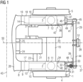
- Fig. 1 shows a floor plan of a chassis of a rail vehicle in a schematic and partial representation.
- the chassis has a first wheel set 1 and an in Fig. 1 invisible second set of wheels.
- the first wheelset 1 is internally mounted, ie a first wheelset bearing device 2 and a second wheelset bearing device 3 of the first wheelset 1 are arranged within an area delimited by a first wheel 4 and a second wheel 5 of the first wheelset 1.
- the second wheelset has the same design as the first wheelset 1 and is also designed as an internally mounted wheelset.
- the first wheelset bearing device 2 and the second wheelset bearing device 3 include wheelset bearings of the first wheelset 1. Furthermore, the first wheelset bearing device 2 has a first wheelset bearing housing 6, the second wheelset bearing device 3 has a second wheelset bearing housing 7.
- a chassis frame 8 is coupled to the first wheelset 1 and the second wheelset.
- a first primary spring 11 is provided between a first longitudinal member 9 of the chassis frame 8 and the first wheelset bearing housing 6, and a second primary spring 12 is provided between a second longitudinal member 10 of the chassis frame 8 and the second wheelset bearing housing 7.
- a first wheelset guiding device 13 is provided between the first longitudinal member 9 and the first wheelset 1
- a second wheelset guiding device 14 is provided between the second longitudinal member 10 and the first wheelset 1.
- the first wheelset guiding device 13 has a first Swing arm 15 and a first wheelset guide bushing 17.
- the first swing arm 15 is formed in one piece with the first axle bearing housing 6.
- the first swing arm 15 is coupled to the chassis frame 8 via the first wheelset guide bushing 17.
- the second wheelset guide device 14 has the same design as the first wheelset guide device 13 and includes a second swing arm 16 and a second wheelset guide bushing 18, via which the second swing arm 16 is connected to the chassis frame 8.
- the second wheel set is connected to the chassis frame 8 according to the same principle as the first wheel set 1.
- a first gear 20 is connected to a wheelset shaft 19 of the first wheelset 1, whereby driving forces and torques are transmitted from an electric first drive motor 21 via a first clutch 22, which is arranged between the first drive motor 21 and the first gear 20, and the first gear 20 be transferred to the first wheelset 1.
- the drive motor 21 is connected to the first longitudinal member 9 via a first engine mount 23 and to a cross member 26 of the chassis frame 8 via a second engine mount 24 and a third engine mount 25
- the first transmission 20 is connected to the second longitudinal member 10 via a transmission torque support 27.
- the chassis has a second drive motor, a second transmission and a second clutch, which in Fig. 1 are not visible and are designed according to the same principles as the first drive motor 21, the first transmission 20 and the first clutch 22 and are connected to each other and to the chassis frame 8 and the second wheelset.
- the support arrangement is therefore designed as an antenna support arrangement and has a support device 29 designed as an antenna support.
- the carrying device 29 is connected in an articulated and elastic manner to the first longitudinal beam 9 and in an articulated and elastic manner to the second longitudinal beam 10.
- a pendulum support 30 made of steel is arranged between the carrying device 29 and the first longitudinal beam 9.
- the pendulum support 30 is connected to the carrying device 29 by means of a first swivel joint 31 and to the first longitudinal beam 9 by means of a second swivel joint 32.
- the first swivel joint 31 and the second swivel joint 32 are designed as bush-shaped metal elastomer elements, which have an elastic behavior in particular in the direction of their longitudinal joint axes and radially with respect to their longitudinal joint axes.
- a first longitudinal joint axis 37 of the first swivel joint 31 is arranged at right angles to a second longitudinal joint axis 38 of the second swivel joint 32.
- the second longitudinal joint axis 38 is aligned parallel to a chassis transverse axis 43.
- the carrying device 29 is thus connected to the first longitudinal member 9 in an articulated manner with respect to the chassis transverse axis 43.
- the carrying device 29 is L-shaped, with a first leg 44 of the carrying device 29 being connected to the first longitudinal beam 9 by means of the pendulum support 30 and a second leg 45 of the carrying device 29 being connected to the second longitudinal beam 10 by means of an elastic element 46.
- the elastic element 46 is designed as a bush-shaped metal elastomer element and has an elastic behavior in the direction of its elastic element longitudinal axis 47 and radially with respect to its elastic element longitudinal axis 47.
- the elastic element longitudinal axis 47 is aligned parallel to the chassis transverse axis 43.
- the carrying device 29 is thus connected to the second longitudinal member 10 in an articulated manner with respect to the chassis transverse axis 43.
- the first leg 44 is tubular and welded to the second leg 45, which is designed as a rocker, i.e. firmly connected to the second leg 45.
- the second leg 45 is cylindrical in the area of the first leg 44 and tapers in the direction of the second longitudinal member 10.
- the first leg 44 and the second leg 45 are made of steel.
- the carrying device 29 is additionally supported in an articulated and elastic manner not on the chassis frame 8, but on the first axle bearing housing 6 and the second axle bearing housing 7, i.e. on further chassis components.
- a first support 48 is arranged between the first leg 44 of the carrying device 29 and the first axle bearing housing 6 and a second support 49 is arranged between the first leg 44 and the second axle bearing housing 7.
- the first support 48 and the second support 49 are made of steel and aligned parallel to a chassis longitudinal axis 50.
- the carrying device 29 is thus supported in the direction of the chassis longitudinal axis 50 on the first axle bearing housing 6 and on the second axle bearing housing 7.
- the first support 48 has a third swivel joint 33 at its first end and a fourth swivel joint 34 at its second end, the first support 48 being coupled to the carrying device 29 via the third swivel joint 33 and to the first axle bearing housing 6 via the fourth swivel joint 34 is.
- the second support 49 is structurally the same as the first support 48 and is connected to the carrying device 29 via a fifth swivel joint 35 and a sixth Swivel joint 36 coupled to the second wheelset bearing housing 7.
- the third swivel joint 33, the fourth swivel joint 34, the fifth swivel joint 35 and the sixth swivel joint 36 are designed as bush-shaped metal elastomer elements and have elastic behavior in the direction of their longitudinal joint axes and radially with respect to their longitudinal joint axes.
- a third longitudinal joint axis 39 of the third swivel joint 33, a fourth longitudinal joint axis 40 of the fourth swivel joint 34, a fifth longitudinal joint axis 41 of the fifth swivel joint 35 and a sixth longitudinal joint axis 42 of the sixth swivel joint 36 are aligned parallel to the chassis transverse axis 43.
- the carrying device 29 is thus supported in an articulated manner with respect to the chassis transverse axis 43 on the first axle bearing housing 6 and on the second axle bearing housing 7.
- a holder 51 is welded to the first leg 44 of the carrying device 29, and the antenna 28 of the train control system, which in this exemplary first embodiment variant of a carrying arrangement according to the invention is designed as a European Train Control System (ETCS), is in turn connected to the holder 51.
- ECS European Train Control System
- the holder 51 and the antenna 28 are arranged centrally with respect to a track, not shown.
- the chassis of Fig. 1 is designed as an internally mounted chassis. According to the invention, however, it is of course conceivable to also use the support arrangement according to the invention for an externally mounted chassis.
- a sensor or sensors of a diagnostic or monitoring system is or are connected to the carrying device 29 (e.g. a camera for detecting track damage, etc.).
- the carrying device 29 is not connected to the second longitudinal beam 10 or to the first longitudinal beam 9 connected and/or not supported on the second axle bearing housing 7 or on the first axle bearing housing 6.
- a sanding device or a sanding pipe or a rail clearer etc. can be connected to such a variant of a carrying arrangement according to the invention.
- a section of a chassis of a rail vehicle with an exemplary second embodiment variant of a support arrangement according to the invention is disclosed as a floor plan in a schematic representation, which is similar to that chassis and that support arrangement shown in Fig. 1 are shown. There will therefore be in Fig. 2 partly the same reference numbers as in Fig. 1 used.
- FIG. 2 shows the carrying arrangement of Fig. 2 a carrying device 29, which is supported in an articulated and elastic manner on a cross member 26 of a chassis frame 8 by means of a first support 48 and a second support 49.
- the first support 48 and the second support 49 are structurally similar and have the same connection technology as the first support 48 and the second support 49, which are shown in Fig. 1 are shown, and aligned parallel to a chassis longitudinal axis 50.
- Fig. 1 In contrast to Fig. 1 are the first support 48 and the second support 49 from Fig. 2 arranged offset towards the center of the carrying device 29.
- FIG. 1 Another difference to Fig. 1 is that the first support 48 and the second support 49 are angled.
- the first support 48 has a first angle 52
- the second support 49 has a second angle 53.
- the first support 48 and the second support 49 are guided obliquely downwards from the carrying device 29.
- the first support 48 runs below a wheelset shaft 19 of the chassis and below a first engine mount 23, over which a first drive motor 21 of the chassis is connected to the chassis frame 8, to the cross member 26.
- the second support 49 runs below the wheelset shaft 19 and below a first gear 20 of the chassis to the cross member 26.
- the first support 48 and the second support 49 are not angled, but curved are.
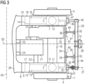
- a section of a chassis of a rail vehicle with an exemplary third embodiment variant of a support arrangement according to the invention is shown as a schematic floor plan, which is similar to that chassis and that support arrangement shown in Fig. 1 and Fig. 2 are revealed. There will therefore be in Fig. 3 partly the same reference numbers as in Fig. 1 and Fig. 2 used.
- the chassis points accordingly Fig. 3 a roll support 54, which is designed as a metallic torsion spring, aligned parallel to a chassis transverse axis 43 and rigidly coupled to a first axle bearing housing 6 and a second axle bearing housing 7 of the chassis.
- a first support 48 and a second support 49 are supported, which are connected to a carrying device 29 of the carrying arrangement.
- the first support 48 and the second support 49 are structurally similar and have the same connection technology as the first support 48 and the second support 49, which are in Fig. 1 are shown. Compared to Fig. 1 have the first support 48 and the second support 49 from Fig. 3 shorter lengths and are arranged offset towards the center of the carrying device 29.
- the carrying device 29 is supported in an articulated and elastic manner on the roll support 54.
Landscapes
- Engineering & Computer Science (AREA)
- Mechanical Engineering (AREA)
- Vibration Prevention Devices (AREA)
- Arrangement Or Mounting Of Propulsion Units For Vehicles (AREA)
Description
- Die Erfindung betrifft eine Trageanordnung für ein Fahrwerk eines Schienenfahrzeugs, insbesondere für eine fahrzeugseitige, bahnsicherungstechnische oder leittechnische Einrichtung, insbesondere Antennentrageanordnung, verbindbar mit einem Fahrwerksrahmen.
- Bei Schienenfahrzeugen ist es oft erforderlich, bestimmte fahrzeugseitige Einrichtungen nahe einem Fahrweg oder einer Bahninfrastruktur anzuordnen, um eine Interaktion zwischen dem Schienenfahrzeug und dem Fahrweg oder der Bahninfrastruktur sicherzustellen, Messungen an Fahrwegen durchzuführen, Daten zwischen dem Schienenfahrzeug und infrastrukturseitigen Einrichtungen zu übertragen (z.B. über Funk) etc.
- Dafür sind häufig Trageanordnungen vorgesehen, welche beispielsweise starr mit einem Fahrwerksrahmen eines Fahrwerks eines Schienenfahrzeugs verbunden sind, wodurch jedoch große dynamische Kräfte in den Fahrwerksrahmen eingeleitet werden können und eine starke Schwingungsanregung erfolgen kann.
- Die Trageanordnung selbst und Komponenten, welche mit der Trageanordnung verbunden sind, weisen mitunter hohe Massen auf und belasten den Fahrwerksrahmen häufig stark.
- Weiterhin müssen beispielsweise Antennen eines Zugbeeinflussungssystems oft an einer bestimmten Position auf der Trageanordnung (z.B. mittig) angeordnet sein, um z.B. eine Datenübertragung mit einer infrastrukturseitigen Balise in Gleismitte zu ermöglichen.
- Aus dem Stand der Technik ist beispielsweise die
CN 110733525 A bekannt, in welcher Trageanordnungen für Antennen gezeigt sind. Diese Trageanordnungen sind mit Längsträgern eines Fahrwerksrahmens eines Fahrwerks eines Schienenfahrzeugs verbunden und umfassen gekrümmte Stangen, welche eine dem Fahrwerk vorgelagerte Anordnung der Antennen im Bereich vor Rädern des Fahrwerks ermöglichen. - Es ist jedoch nicht ersichtlich, inwieweit die Trageanordnung dafür ausgebildet ist, Antennen auch weiter von den Rädern entfernt (z.B. in Richtung Fahrwerksmitte) anzuordnen. Weiterhin zeigt die
EP 3 243 724 A1 ein Fahrwerk für ein Schienenfahrzeug, wobei auf einem Fahrwerksrahmen und einem Rad ein Adapter gelagert ist, auf welchem beispielsweise Stromabnehmer oder Zugsicherungsantennen angeordnet sein können. - Der Adapter ist seitlich am Fahrwerk vorgesehen. Es ist nicht ersichtlich, inwieweit sich der Adapter auch für Komponenten eignet, welche beispielsweise in einem dem Fahrwerk vorgelagerten Bereich angeordnet werden sollen.
- Weiterhin zeigt die
US2019/329659 A1 eine mit einem Längsträger des Fahrwerks verbindbare quer eingebaute Trageanordnung. - Der Erfindung liegt daher die Aufgabe zugrunde, eine gegenüber dem Stand der Technik weiterentwickelte, distanzüberbrückende Trageanordnung mit mechanischer Entkopplung in Bezug auf den Fahrwerksrahmen anzugeben. Erfindungsgemäß wird diese Aufgabe gelöst mit einer Trageanordnung der eingangs genannten Art, bei der eine Tragevorrichtung vorgesehen ist, welche gelenkig und elastisch mit zumindest einem ersten Längsträger des Fahrwerksrahmens verbindbar ist und zusätzlich zumindest an dem Fahrwerksrahmen oder an zumindest einer weiteren Fahrwerkskomponente gelenkig und elastisch abstützbar ist, wobei die Tragevorrichtung mittels einer Pendelstütze mit dem zumindest ersten Längsträger verbindbar ist und die Tragevorrichtung L-förmig ausgebildet ist, wobei ein erster Schenkel der Tragevorrichtung mittels der Pendelstütze mit dem zumindest ersten Längsträger verbindbar ist.
- Durch diese Maßnahme kann bei Verbindung der Tragevorrichtung mit dem Fahrwerksrahmen dieser leichter gebaut werden, da die Tragevorrichtung aufgrund einer elastischen Lagerung auf dem ersten Längsträger den Fahrwerksrahmen mechanisch, insbesondere dynamisch, nur moderat belastet.
- Weiterhin werden bei Abstützung der Tragevorrichtung an dem Fahrwerksrahmen oder der weiteren Fahrwerkskomponente aufgrund dieser Abstützung eine verteilte Krafteinleitung in das Fahrwerk erzielt und die Tragevorrichtung in Position gehalten.
- Mittels der erfindungsgemäßen Trageanordnung wird eine geringe Schwingungsanregung erreicht. Bei Verbindung der Trageanordnung mit dem Fahrwerk werden aufgrund der Lagerung der Tragevorrichtung auf dem ersten Längsträger sowie aufgrund der zusätzlichen Abstützung der Tragevorrichtung an dem Fahrwerksrahmen oder der weiteren Fahrwerkskomponente dynamisch wirksame Trägheitsmomente um den Drehpunkt des Fahrwerks gering gehalten, wodurch fahrdynamische Verbesserungen erzielt werden.
- Ferner werden aufgrund der Pendelstütze auftretende Relativbewegungen zwischen dem Fahrwerksrahmen und der Tragevorrichtung ausgeglichen.
- Eine L-förmige Ausbildung der Tragevorrichtung führt bei Verbindung des ersten Schenkels mit dem ersten Längsträger mittels der Pendelstütze zu einer großen Stabilität und zu vorteilhaften Festigkeitseigenschaften der Tragevorrichtung.
- Ferner ist es hilfreich, wenn der erste Schenkel rohrförmig ausgebildet ist und fest mit einem als Schwinge ausgeführten zweiten Schenkel der Tragevorrichtung verbunden ist.
- Durch diese Maßnahme wird eine Massenreduktion der Tragevorrichtung bewirkt, ohne die vorteilhaften Festigkeitseigenschaften der Tragevorrichtung wesentlich zu beeinflussen.
- Um die Tragevorrichtung in Position zu halten, ist es günstig, wenn die Tragevorrichtung mittels zumindest einer ersten Stütze an zumindest einem ersten Radsatzlagergehäuse des Fahrwerks abstützbar ist.
- Alternativ kann es jedoch auch vorteilhaft sein, wenn die Tragevorrichtung mittels zumindest einer ersten Stütze an einem Querträger des Fahrwerksrahmens abstützbar ist.
- Eine weitere alternative Lösung zur Abstützung der Tragevorrichtung wird erreicht, wenn die Tragevorrichtung mittels zumindest einer ersten Stütze an einer Wankstütze des Schienenfahrzeugs abstützbar ist.
- Ist als weitere Fahrwerkskomponente, an welcher die Tragevorrichtung abstützbar ist, das erste Radsatzlagergehäuse oder die Wankstütze vorgesehen, so wird eine Entlastung des Fahrwerksrahmens bewirkt.
- Um die erste Stütze beispielsweise unter einem Radsatz, unter einem Antriebsmotor, einem Getriebe etc. zu dem Fahrwerksrahmen oder zu der weiteren Fahrwerkskomponente führen zu können, ist es hilfreich, wenn die zumindest erste Stütze gewinkelt oder gekrümmt ausgebildet ist.
- Eine zusätzliche Stabilisierung bei zugleich mechanisch entkoppelter Lagerung der erfindungsgemäßen Trageanordnung wird ermöglicht, wenn die Tragevorrichtung gelenkig und elastisch mit einem zweiten Längsträger des Fahrwerksrahmens verbindbar ist, wobei ein zweiter Schenkel der Tragevorrichtung mittels eines Elastikelements mit dem zweiten Längsträger verbindbar ist.
- Nachfolgend wird die Erfindung anhand von Ausführungsbeispielen näher erläutert.
- Es zeigen beispielhaft:
- Fig. 1:
- Einen Ausschnitt aus einem Fahrwerk eines Schienenfahrzeugs in schematischer Grundrissdarstellung mit einer beispielhaften ersten Ausführungsvariante einer erfindungsgemäßen Trageanordnung, welche an Radsatzlagergehäusen abgestützt ist,
- Fig. 2:
- Einen Ausschnitt aus einem Fahrwerk eines Schienenfahrzeugs in schematischer Grundrissdarstellung mit einer beispielhaften zweiten Ausführungsvariante einer erfindungsgemäßen Trageanordnung, welche an einem Querträger eines Fahrwerksrahmens abgestützt ist, und
- Fig. 3:
- Einen Ausschnitt aus einem Fahrwerk eines Schienenfahrzeugs in schematischer Grundrissdarstellung mit einer beispielhaften dritten Ausführungsvariante einer erfindungsgemäßen Trageanordnung, welche an einer Wankstütze abgestützt ist.
-
Fig. 1 zeigt einen Grundriss eines Fahrwerks eines Schienenfahrzeugs in schematischer und ausschnittsweiser Darstellung. - Das Fahrwerk weist einen ersten Radsatz 1 sowie einen in
Fig. 1 nicht sichtbaren zweiten Radsatz auf. Der erste Radsatz 1 ist innengelagert, d.h. eine erste Radsatzlagervorrichtung 2 und eine zweite Radsatzlagervorrichtung 3 des ersten Radsatzes 1 sind innerhalb eines von einem ersten Rad 4 und einem zweiten Rad 5 des ersten Radsatzes 1 begrenzten Bereichs angeordnet. - Der zweite Radsatz ist konstruktiv gleich wie der erste Radsatz 1 ausgebildet und ebenfalls als innengelagerter Radsatz ausgeführt.
- Die erste Radsatzlagervorrichtung 2 und die zweite Radsatzlagervorrichtung 3 umfassen Radsatzlager des ersten Radsatzes 1. Weiterhin weist die erste Radsatzlagervorrichtung 2 ein erstes Radsatzlagergehäuse 6 auf, die zweite Radsatzlagervorrichtung 3 ein zweites Radsatzlagergehäuse 7.
- Mit dem ersten Radsatz 1 und dem zweiten Radsatz ist ein Fahrwerksrahmen 8 gekoppelt.
- Zur Verbindung des ersten Radsatzes 1 mit dem Fahrwerksrahmen 8 ist zwischen einem ersten Längsträger 9 des Fahrwerksrahmens 8 und dem ersten Radsatzlagergehäuse 6 eine erste Primärfeder 11 vorgesehen, zwischen einem zweiten Längsträger 10 des Fahrwerksrahmens 8 und dem zweiten Radsatzlagergehäuse 7 eine zweite Primärfeder 12.
- Weiterhin sind zur Kopplung des ersten Radsatzes 1 an den Fahrwerksrahmen 8 zwischen dem ersten Längsträger 9 und dem ersten Radsatz 1 eine erste Radsatzführungsvorrichtung 13 vorgesehen, zwischen dem zweiten Längsträger 10 und dem ersten Radsatz 1 eine zweite Radsatzführungsvorrichtung 14. Die erste Radsatzführungsvorrichtung 13 weist einen ersten Schwingarm 15 sowie eine erste Radsatzführungsbuchse 17 auf. Der erste Schwingarm 15 ist einstückig mit dem ersten Radsatzlagergehäuse 6 ausgebildet.
- Über die erste Radsatzführungsbuchse 17 ist der erste Schwingarm 15 an den Fahrwerksrahmen 8 gekoppelt. Die zweite Radsatzführungsvorrichtung 14 ist konstruktiv gleich wie die erste Radsatzführungsvorrichtung 13 ausgeführt und umfasst einen zweiten Schwingarm 16 sowie eine zweite Radsatzführungsbuchse 18, über welche der zweite Schwingarm 16 mit dem Fahrwerksrahmen 8 verbunden ist. Der zweite Radsatz ist nach gleichem Prinzip wie der erste Radsatz 1 mit dem Fahrwerksrahmen 8 verbunden.
- Mit einer Radsatzwelle 19 des ersten Radsatzes 1 ist ein erstes Getriebe 20 verbunden, wodurch Antriebskräfte und - Drehmomente von einem elektrischen ersten Antriebsmotor 21 über eine erste Kupplung 22, welche dem ersten Antriebsmotor 21 und dem ersten Getriebe 20 zwischengeordnet ist, und das erste Getriebe 20 auf den ersten Radsatz 1 übertragen werden. Der Antriebsmotor 21 ist über ein erstes Motorlager 23 mit dem ersten Längsträger 9 sowie über ein zweites Motorlager 24 und ein drittes Motorlager 25 mit einem Querträger 26 des Fahrwerksrahmens 8 verbunden
Das erste Getriebe 20 ist über eine Getriebe-Drehmomentstütze 27 mit dem zweiten Längsträger 10 verbunden. - Das Fahrwerk weist einen zweiten Antriebsmotor, ein zweites Getriebe und eine zweite Kupplung auf, welche in
Fig. 1 nicht sichtbar sind und nach selben Prinzipien wie der erste Antriebsmotor 21, das erste Getriebe 20 und die erste Kupplung 22 ausgeführt und miteinander sowie mit dem Fahrwerksrahmen 8 und dem zweiten Radsatz verbunden sind. - Mit dem Fahrwerk ist eine beispielhafte erste Ausführungsvariante einer erfindungsgemäßen Trageanordnung für eine Antenne 28 eines Zugbeeinflussungssystems, d.h. einer fahrzeugseitigen, bahnsicherungstechnischen Einrichtung, verbunden.
- Die Trageanordnung ist demnach als Antennentrageanordnung ausgebildet und weist eine als Antennenträger ausgebildete Tragevorrichtung 29 auf.
- Die Tragevorrichtung 29 ist gelenkig und elastisch mit dem ersten Längsträger 9 sowie gelenkig und elastisch mit dem zweiten Längsträger 10 verbunden. Zwischen der Tragevorrichtung 29 und dem ersten Längsträger 9 ist eine Pendelstütze 30 aus Stahl angeordnet.
- Die Pendelstütze 30 ist mittels eines ersten Drehgelenks 31 mit der Tragevorrichtung 29 und mittels eines zweiten Drehgelenks 32 mit dem ersten Längsträger 9 verbunden.
- Das erste Drehgelenk 31 und das zweite Drehgelenk 32 sind als buchsenförmige Metall-Elastomerelemente ausgeführt, welche insbesondere in Richtung ihrer Gelenkslängsachsen und radial bezüglich ihrer Gelenkslängsachsen ein elastisches Verhalten aufweisen.
- Eine erste Gelenkslängsachse 37 des ersten Drehgelenks 31 ist rechtwinklig zu einer zweiten Gelenkslängsachse 38 des zweiten Drehgelenks 32 angeordnet.
- Die zweite Gelenkslängsachse 38 ist parallel zu einer Fahrwerksquerachse 43 ausgerichtet. Die Tragevorrichtung 29 ist somit gelenkig bezüglich der Fahrwerksquerachse 43 mit dem ersten Längsträger 9 verbunden.
- Die Tragevorrichtung 29 ist L-förmig ausgebildet, wobei ein erster Schenkel 44 der Tragevorrichtung 29 mittels der Pendelstütze 30 mit dem ersten Längsträger 9 und ein zweiter Schenkel 45 der Tragevorrichtung 29 mittels eines Elastikelements 46 mit dem zweiten Längsträger 10 verbunden ist.
- Das Elastikelement 46 ist als buchsenförmiges Metall-Elastomerelement ausgebildet und weist in Richtung seiner Elastikelementlängsachse 47 sowie radial bezüglich seiner Elastikelementlängsachse 47 ein elastisches Verhalten auf. Die Elastikelementlängsachse 47 ist parallel zu der Fahrwerksquerachse 43 ausgerichtet. Die Tragevorrichtung 29 ist somit bezüglich der Fahrwerksquerachse 43 gelenkig mit dem zweiten Längsträger 10 verbunden.
- Der erste Schenkel 44 ist rohrförmig ausgebildet und mit dem als Schwinge ausgeführten zweiten Schenkel 45 verschweißt, d.h. fest mit dem zweiten Schenkel 45 verbunden.
- Der zweite Schenkel 45 ist im Bereich des ersten Schenkels 44 zylindrisch ausgebildet und verjüngt sich in Richtung des zweiten Längsträgers 10.
- Der erste Schenkel 44 und der zweite Schenkel 45 sind in Stahl ausgeführt.
- In dieser beispielhaften ersten Ausführungsvariante einer erfindungsgemäßen Trageanordnung ist die Tragevorrichtung 29 zusätzlich nicht an dem Fahrwerksrahmen 8, sondern an dem ersten Radsatzlagergehäuse 6 und dem zweiten Radsatzlagergehäuse 7, d.h. an weiteren Fahrwerkskomponenten, gelenkig und elastisch abgestützt.
- Hierzu ist zwischen dem ersten Schenkel 44 der Tragevorrichtung 29 und dem ersten Radsatzlagergehäuse 6 eine erste Stütze 48 sowie zwischen dem ersten Schenkel 44 und dem zweiten Radsatzlagergehäuse 7 eine zweite Stütze 49 angeordnet. Die erste Stütze 48 und die zweite Stütze 49 sind in Stahl ausgeführt und parallel zu einer Fahrwerkslängsachse 50 ausgerichtet. Die Tragevorrichtung 29 ist somit in Richtung der Fahrwerkslängsachse 50 an dem ersten Radsatzlagergehäuse 6 und an dem zweiten Radsatzlagergehäuse 7 abgestützt.
- Die erste Stütze 48 weist an ihrem ersten Ende ein drittes Drehgelenk 33 und an ihrem zweiten Ende ein viertes Drehgelenk 34 auf, wobei die erste Stütze 48 über das dritte Drehgelenk 33 mit der Tragevorrichtung 29 und über das vierte Drehgelenk 34 mit dem ersten Radsatzlagergehäuse 6 gekoppelt ist.
- Die zweite Stütze 49 ist konstruktiv gleich wie die erste Stütze 48 ausgebildet und ist über ein fünftes Drehgelenk 35 mit der Tragevorrichtung 29 sowie über ein sechstes Drehgelenk 36 mit dem zweiten Radsatzlagergehäuse 7 gekoppelt.
- Das dritte Drehgelenk 33, das vierte Drehgelenk 34, das fünfte Drehgelenk 35 sowie das sechste Drehgelenk 36 sind als buchsenförmige Metall-Elastomerelemente ausgebildet und weisen ein elastisches Verhalten in Richtung ihrer Gelenkslängsachsen sowie radial bezüglich ihrer Gelenkslängsachsen auf.
- Eine dritte Gelenkslängsachse 39 des dritten Drehgelenks 33, eine vierte Gelenkslängsachse 40 des vierten Drehgelenks 34, eine fünfte Gelenkslängsachse 41 des fünften Drehgelenks 35 und eine sechste Gelenkslängsachse 42 des sechsten Drehgelenks 36 sind parallel zu der Fahrwerksquerachse 43 ausgerichtet.
- Die Tragevorrichtung 29 ist somit gelenkig bezüglich der Fahrwerksquerachse 43 an dem ersten Radsatzlagergehäuse 6 und an dem zweiten Radsatzlagergehäuse 7 abgestützt.
- Mit dem ersten Schenkel 44 der Tragevorrichtung 29 ist ein Halter 51 verschweißt, mit dem Halter 51 ist wiederum die Antenne 28 des Zugbeeinflussungssystems, das in dieser beispielhaften ersten Ausführungsvariante einer erfindungsgemäßen Trageanordnung als European Train Control System (ETCS) ausgeführt ist, verbunden.
- Der Halter 51 und die Antenne 28 sind mittig in Bezug auf ein nicht dargestelltes Gleis angeordnet.
- Das Fahrwerk von
Fig. 1 ist als innengelagertes Fahrwerk ausgebildet. Erfindungsgemäß ist es jedoch selbstverständlich vorstellbar, die erfindungsgemäße Trageanordnung auch für ein außengelagertes Fahrwerk einzusetzen. - Weiterhin ist es vorstellbar, dass mit der Tragevorrichtung 29 beispielsweise ein Sensor oder Sensoren eines Diagnose- oder Überwachungssystems verbunden ist oder sind (z.B. eine Kamera zur Detektion von Gleisschäden etc.).
- Ferner ist es denkbar, dass die Tragevorrichtung 29 nicht mit dem zweiten Längsträger 10 oder mit dem ersten Längsträger 9 verbunden und/oder nicht an dem zweiten Radsatzlagergehäuse 7 oder an dem ersten Radsatzlagergehäuse 6 abgestützt ist. Mit einer derartigen Variante einer erfindungsgemäßen Trageanordnung kann beispielsweise eine Sandungsvorrichtung bzw. ein Sandungsrohr oder ein Schienenräumer etc. verbunden sein.
- In
Fig. 2 ist ausschnittsweise ein Fahrwerk eines Schienenfahrzeugs mit einer beispielhaften zweiten Ausführungsvariante einer erfindungsgemäßen Trageanordnung als Grundriss in schematischer Darstellung offenbart, welche jenem Fahrwerk und jener Trageanordnung ähneln, die inFig. 1 gezeigt sind. Es werden daher inFig. 2 teilweise gleiche Bezugszeichen wie inFig. 1 verwendet. - Im Unterschied zu
Fig. 1 weist die Trageanordnung vonFig. 2 eine Tragevorrichtung 29 auf, welche mittels einer ersten Stütze 48 und einer zweiten Stütze 49 an einem Querträger 26 eines Fahrwerksrahmens 8 gelenkig und elastisch abgestützt ist. - Die erste Stütze 48 und die zweite Stütze 49 sind konstruktiv ähnlich und verbindungstechnisch gleich wie jene erste Stütze 48 und jene zweite Stütze 49 ausgeführt, die in
Fig. 1 dargestellt sind, und parallel zu einer Fahrwerkslängsachse 50 ausgerichtet. - Im Unterschied zu
Fig. 1 sind die erste Stütze 48 und die zweite Stütze 49 vonFig. 2 in Richtung der Mitte der Tragevorrichtung 29 versetzt angeordnet. - Ein weiterer Unterschied zu
Fig. 1 besteht darin, dass die erste Stütze 48 und die zweite Stütze 49 gewinkelt ausgebildet sind. Die erste Stütze 48 weist einen ersten Winkel 52 auf, die zweite Stütze 49 einen zweiten Winkel 53. Dadurch sind die erste Stütze 48 und die zweite Stütze 49 von der Tragevorrichtung 29 ausgehend schräg nach unten geführt. Ausgehend von dem ersten Winkel 52 verläuft die erste Stütze 48 unterhalb einer Radsatzwelle 19 des Fahrwerks sowie unterhalb eines ersten Motorlagers 23, über welches ein erster Antriebsmotor 21 des Fahrwerks mit dem Fahrwerksrahmen 8 verbunden ist, zu dem Querträger 26. - Ausgehend von dem zweiten Winkel 53 verläuft die zweite Stütze 49 unterhalb der Radsatzwelle 19 sowie unterhalb eines ersten Getriebes 20 des Fahrwerks zu dem Querträger 26. Erfindungsgemäß ist es auch vorstellbar, dass die erste Stütze 48 und die zweite Stütze 49 nicht gewinkelt, sondern gekrümmt ausgebildet sind.
- In
Fig. 3 ist ausschnittsweise ein Fahrwerk eines Schienenfahrzeugs mit einer beispielhaften dritten Ausführungsvariante einer erfindungsgemäßen Trageanordnung als schematischer Grundriss dargestellt, welche jenem Fahrwerk und jener Trageanordnung ähneln, die inFig. 1 undFig. 2 offenbart sind. Es werden daher inFig. 3 teilweise gleiche Bezugszeichen wie inFig. 1 undFig. 2 verwendet. Im Unterschied zuFig. 1 undFig. 2 weist das Fahrwerk gemäßFig. 3 eine Wankstütze 54 auf, welche als metallische Torsionsfeder ausgebildet, parallel zu einer Fahrwerksquerachse 43 ausgerichtet und starr mit einem ersten Radsatzlagergehäuse 6 sowie einem zweiten Radsatzlagergehäuse 7 des Fahrwerks gekoppelt ist. - An der Wankstütze 54, d.h. an einer Fahrwerkskomponente, sind eine erste Stütze 48 und eine zweite Stütze 49 abgestützt, die mit einer Tragevorrichtung 29 der Trageanordnung verbunden sind.
- Die erste Stütze 48 und die zweite Stütze 49 sind konstruktiv ähnlich und verbindungstechnisch gleich wie jene erste Stütze 48 und jene zweite Stütze 49, die in
Fig. 1 gezeigt sind, ausgebildet. Im Vergleich zuFig. 1 weisen die erste Stütze 48 und die zweite Stütze 49 vonFig. 3 kürzere Längen auf und sind in Richtung der Mitte der Tragevorrichtung 29 versetzt angeordnet. - Mittels der ersten Stütze 48 und der zweiten Stütze 49, welche parallel zu einer Fahrwerkslängsachse 50 ausgerichtet sind, ist die Tragevorrichtung 29 gelenkig und elastisch an der Wankstütze 54 abgestützt.
-
- 1
- Erster Radsatz
- 2
- Erste Radsatzlagervorrichtung
- 3
- Zweite Radsatzlagervorrichtung
- 4
- Erstes Rad
- 5
- Zweites Rad
- 6
- Erstes Radsatzlagergehäuse
- 7
- Zweites Radsatzlagergehäuse
- 8
- Fahrwerksrahmen
- 9
- Erster Längsträger
- 10
- Zweiter Längsträger
- 11
- Erste Primärfeder
- 12
- Zweite Primärfeder
- 13
- Erste Radsatzführungsvorrichtung
- 14
- Zweite Radsatzführungsvorrichtung
- 15
- Erster Schwingarm
- 16
- Zweiter Schwingarm
- 17
- Erste Radsatzführungsbuchse
- 18
- Zweite Radsatzführungsbuchse
- 19
- Radsatzwelle
- 20
- Erstes Getriebe
- 21
- Erster Antriebsmotor
- 22
- Erste Kupplung
- 23
- Erstes Motorlager
- 24
- Zweites Motorlager
- 25
- Drittes Motorlager
- 26
- Querträger
- 27
- Getriebe-Drehmomentstütze
- 28
- Antenne
- 29
- Tragevorrichtung
- 30
- Pendelstütze
- 31
- Erstes Drehgelenk
- 32
- Zweites Drehgelenk
- 33
- Drittes Drehgelenk
- 34
- Viertes Drehgelenk
- 35
- Fünftes Drehgelenk
- 36
- Sechstes Drehgelenk
- 37
- Erste Gelenkslängsachse
- 38
- Zweite Gelenkslängsachse
- 39
- Dritte Gelenkslängsachse
- 40
- Vierte Gelenkslängsachse
- 41
- Fünfte Gelenkslängsachse
- 42
- Sechste Gelenkslängsachse
- 43
- Fahrwerksquerachse
- 44
- Erster Schenkel
- 45
- Zweiter Schenkel
- 46
- Elastikelement
- 47
- Elastikelementlängsachse
- 48
- Erste Stütze
- 49
- Zweite Stütze
- 50
- Fahrwerkslängsachse
- 51
- Halter
- 52
- Erster Winkel
- 53
- Zweiter Winkel
- 54
- Wankstütze
Claims (14)
- Trageanordnung für ein Fahrwerk eines Schienenfahrzeugs, insbesondere für eine fahrzeugseitige, bahnsicherungstechnische oder leittechnische Einrichtung, insbesondere Antennentrageanordnung, verbindbar mit einem Fahrwerksrahmen (8), wobei eine Tragevorrichtung (29) vorgesehen ist, welche gelenkig und elastisch mit zumindest einem ersten Längsträger (9) des Fahrwerksrahmens (8) verbindbar ist und zusätzlich zumindest an dem Fahrwerksrahmen (8) oder an zumindest einer weiteren Fahrwerkskomponente gelenkig und elastisch abstützbar ist, wobei die Tragevorrichtung (29) mittels einer Pendelstütze (30) mit dem zumindest ersten Längsträger (9) verbindbar ist, dadurch gekennzeichnet, dass die Tragevorrichtung (29) L-förmig ausgebildet ist, wobei ein erster Schenkel (44) der Tragevorrichtung (29) mittels der Pendelstütze (30) mit dem zumindest ersten Längsträger (9) verbindbar ist.
- Trageanordnung nach Anspruch 1, dadurch gekennzeichnet, dass der erste Schenkel (44) rohrförmig ausgebildet ist und fest mit einem als Schwinge ausgeführten zweiten Schenkel (45) der Tragevorrichtung (29) verbunden ist.
- Trageanordnung nach Anspruch 1 oder 2, dadurch gekennzeichnet, dass die Pendelstütze (30) mittels eines ersten Drehgelenks (31) mit der Tragevorrichtung (29) verbunden ist und mittels eines zweiten Drehgelenks (32) mit dem zumindest ersten Längsträger (9) verbindbar ist.
- Trageanordnung nach Anspruch 3, dadurch gekennzeichnet, dass eine erste Gelenkslängsachse (37) des ersten Drehgelenks (31) rechtwinklig zu einer zweiten Gelenkslängsachse (38) des zweiten Drehgelenks (32) angeordnet ist.
- Trageanordnung nach einem der Ansprüche 1 bis 4, dadurch gekennzeichnet, dass die Tragevorrichtung (29) mit dem zumindest ersten Längsträger (9) gelenkig bezüglich einer Fahrwerksquerachse (43) verbindbar ist.
- Trageanordnung nach einem der Ansprüche 1 bis 5, dadurch gekennzeichnet, dass die Tragevorrichtung (29) an dem Fahrwerksrahmen (8) oder an der weiteren Fahrwerkskomponente in Richtung einer Fahrwerkslängsachse (50) abstützbar ist.
- Trageanordnung nach einem der Ansprüche 1 bis 6, dadurch gekennzeichnet, dass die Tragevorrichtung (29) an dem Fahrwerksrahmen (8) oder an der weiteren Fahrwerkskomponente gelenkig bezüglich der Fahrwerksquerachse (43) abstützbar ist.
- Trageanordnung nach einem der Ansprüche 1 bis 7, dadurch gekennzeichnet, dass die Tragevorrichtung (29) mittels zumindest einer ersten Stütze (48) an zumindest einem ersten Radsatzlagergehäuse (6) des Fahrwerks abstützbar ist.
- Trageanordnung nach einem der Ansprüche Anspruch 1 bis 7, dadurch gekennzeichnet, dass die Tragevorrichtung (29) mittels zumindest einer ersten Stütze (48) an einem Querträger (26) des Fahrwerksrahmens (8) abstützbar ist.
- Trageanordnung nach einem der Ansprüche 1 bis 7, dadurch gekennzeichnet, dass die Tragevorrichtung (29) mittels zumindest einer ersten Stütze (48) an einer Wankstütze (54) des Schienenfahrzeugs abstützbar ist.
- Trageanordnung nach einem der Ansprüche 8 bis 10, dadurch gekennzeichnet, dass die zumindest erste Stütze (48) an einem ersten Ende ein drittes Drehgelenk (33) und an einem zweiten Ende ein viertes Drehgelenk (34) aufweist.
- Trageanordnung nach einem der Ansprüche 8 bis 11, dadurch gekennzeichnet, dass die zumindest erste Stütze (48) gewinkelt oder gekrümmt ausgebildet ist.
- Trageanordnung nach einem der Ansprüche 1 bis 12, dadurch gekennzeichnet, dass die Tragevorrichtung (29) gelenkig und elastisch mit einem zweiten Längsträger (10) des Fahrwerksrahmens (8) verbindbar ist, wobei ein zweiter Schenkel (45) der Tragevorrichtung (29) mittels eines Elastikelements (46) mit dem zweiten Längsträger (10) verbindbar ist.
- Fahrwerk eines Schienenfahrzeugs mit einer Trageanordnung nach einem der Ansprüche 1 bis 13.
Applications Claiming Priority (2)
| Application Number | Priority Date | Filing Date | Title |
|---|---|---|---|
| ATA50266/2020A AT523656B1 (de) | 2020-03-31 | 2020-03-31 | Trageanordnung für ein Fahrwerk eines Schienenfahrzeugs |
| PCT/EP2021/057763 WO2021198021A1 (de) | 2020-03-31 | 2021-03-25 | Trageanordnung für ein fahrwerk eines schienenfahrzeugs |
Publications (2)
| Publication Number | Publication Date |
|---|---|
| EP4100295A1 EP4100295A1 (de) | 2022-12-14 |
| EP4100295B1 true EP4100295B1 (de) | 2024-01-10 |
Family
ID=75478003
Family Applications (1)
| Application Number | Title | Priority Date | Filing Date |
|---|---|---|---|
| EP21718032.2A Active EP4100295B1 (de) | 2020-03-31 | 2021-03-25 | Trageanordnung für ein fahrwerk eines schienenfahrzeugs |
Country Status (5)
| Country | Link |
|---|---|
| US (1) | US12594975B2 (de) |
| EP (1) | EP4100295B1 (de) |
| CN (1) | CN219257341U (de) |
| AT (1) | AT523656B1 (de) |
| WO (1) | WO2021198021A1 (de) |
Families Citing this family (2)
| Publication number | Priority date | Publication date | Assignee | Title |
|---|---|---|---|---|
| WO2021063947A1 (de) * | 2019-09-30 | 2021-04-08 | Siemens Mobility Austria Gmbh | Fahrwerk eines schienenfahrzeugs |
| DE102022206109A1 (de) | 2022-06-20 | 2023-12-21 | Siemens Mobility GmbH | Fahrwerk für ein Schienenfahrzeug und Schienenfahrzeug |
Family Cites Families (10)
| Publication number | Priority date | Publication date | Assignee | Title |
|---|---|---|---|---|
| US6079335A (en) | 1999-02-23 | 2000-06-27 | Buckeye Steel Castings Company | Unsprung third rail collector beam support for a swing arm primary suspension railway truck |
| JP2004148948A (ja) | 2002-10-30 | 2004-05-27 | Kawasaki Heavy Ind Ltd | 鉄道車両用台車 |
| CN202094272U (zh) * | 2011-05-31 | 2011-12-28 | 长春轨道客车股份有限公司 | 高速动车组转向架用atp天线偏置悬挂装置 |
| AT516912A3 (de) * | 2015-02-17 | 2017-12-15 | Siemens Ag Oesterreich | Verbindungsträger für zwei Längsträger eines Schienenfahrzeugs |
| CN204956505U (zh) * | 2015-09-30 | 2016-01-13 | 南车南京浦镇车辆有限公司 | 一种用于轨道车辆的天线设备固定装置 |
| CN105216823B (zh) * | 2015-09-30 | 2018-05-25 | 中车南京浦镇车辆有限公司 | 一种用于轨道车辆的天线设备固定装置 |
| AT518697B1 (de) | 2016-05-10 | 2021-12-15 | Siemens Mobility Austria Gmbh | Fahrwerk für ein Schienenfahrzeug |
| CN106043343A (zh) * | 2016-06-13 | 2016-10-26 | 中车青岛四方机车车辆股份有限公司 | 轨道车辆转向架水平梁防脱吊挂装置及其安装方法、轨道车辆 |
| JP6726612B2 (ja) * | 2016-12-16 | 2020-07-22 | 川崎重工業株式会社 | 鉄道車両用台車 |
| CN110733525B (zh) | 2019-10-31 | 2025-06-03 | 中车南京浦镇车辆有限公司 | 一种天线支架与转向架的定位结构 |
-
2020
- 2020-03-31 AT ATA50266/2020A patent/AT523656B1/de not_active IP Right Cessation
-
2021
- 2021-03-25 US US17/915,895 patent/US12594975B2/en active Active
- 2021-03-25 WO PCT/EP2021/057763 patent/WO2021198021A1/de not_active Ceased
- 2021-03-25 CN CN202190000396.3U patent/CN219257341U/zh active Active
- 2021-03-25 EP EP21718032.2A patent/EP4100295B1/de active Active
Also Published As
| Publication number | Publication date |
|---|---|
| WO2021198021A1 (de) | 2021-10-07 |
| EP4100295A1 (de) | 2022-12-14 |
| CN219257341U (zh) | 2023-06-27 |
| AT523656B1 (de) | 2021-11-15 |
| US20230202536A1 (en) | 2023-06-29 |
| AT523656A1 (de) | 2021-10-15 |
| US12594975B2 (en) | 2026-04-07 |
Similar Documents
| Publication | Publication Date | Title |
|---|---|---|
| EP4100295B1 (de) | Trageanordnung für ein fahrwerk eines schienenfahrzeugs | |
| EP4013655B1 (de) | Fahrwerk eines schienenfahrzeugs | |
| EP3272614B1 (de) | Fahrwerk für ein schienenfahrzeug | |
| DE102011112053A1 (de) | Einzelradaufhängung und Fahrschemel | |
| EP3544875B1 (de) | Fahrwerk für schienenfahrzeuge | |
| DE102013224582A1 (de) | Fahrwerk für ein Schienenfahrzeug | |
| WO2022161653A1 (de) | Hohlwelle für ein wankstabilisierungssystem für ein fahrzeug, wankstabilisierungssystem und verfahren zum herstellen einer hohlwelle | |
| EP1685014B2 (de) | Angetriebenes fahrwerk für schienenfahrzeuge, insbesondere drehgestelle für niederflurfahrzeuge | |
| WO2009144319A1 (de) | Drehgestell mit geteiltem rahmen und motor-getriebe-kupplungs-einheit | |
| DE102017106085A1 (de) | Radaufhängungsanordnung für ein Fahrzeug | |
| DE102016007496B4 (de) | Antriebsmodul für ein Kraftfahrzeug sowie entsprechendes Kraftfahrzeug | |
| EP4491487A2 (de) | Fahrwerk für ein schienenfahrzeug sowie schienenfahrzeugwagen mit mindestens einem fahrwerk, schienenfahrzeug mit mindestens einem schienenfahrzeugwagen und verfahren zur höheneinstellung eines wagenkastens eines schienenfahrzeugwagens | |
| DE102006004960A1 (de) | Angetriebe Fahrzeugachse mit Einzelradaufhängung | |
| EP3243724A1 (de) | Fahrwerk für ein schienenfahrzeug | |
| EP2061690B1 (de) | Befestigung für einen radsatzlenker eines schienenfahrzeugs | |
| EP4228948B1 (de) | Fahrwerk für ein schienenfahrzeug | |
| DE102017005165A1 (de) | Fahrzeug | |
| EP4121332B1 (de) | Anordnung zur abstützung eines drehmoments | |
| EP3974280B1 (de) | Fahrwerk für ein schienenfahrzeug | |
| AT527594B1 (de) | Antrieb und Fahrwerk für ein Schienenfahrzeug | |
| DE102013210235A1 (de) | Drehmomentstütze für ein Schienenfahrzeug | |
| AT528197B1 (de) | Fahrwerk für ein Schienenfahrzeug und Schienenfahrzeug | |
| EP3750775B1 (de) | Verfahren und vorrichtung zur betrieblichen neigungsbestimmung bei fahrzeugen | |
| DE2709967A1 (de) | Triebfahrzeug, insbesondere schienentriebfahrzeug | |
| DE102021213986A1 (de) | Achsbaugruppe für ein Fahrzeug |
Legal Events
| Date | Code | Title | Description |
|---|---|---|---|
| STAA | Information on the status of an ep patent application or granted ep patent |
Free format text: STATUS: UNKNOWN |
|
| STAA | Information on the status of an ep patent application or granted ep patent |
Free format text: STATUS: THE INTERNATIONAL PUBLICATION HAS BEEN MADE |
|
| PUAI | Public reference made under article 153(3) epc to a published international application that has entered the european phase |
Free format text: ORIGINAL CODE: 0009012 |
|
| STAA | Information on the status of an ep patent application or granted ep patent |
Free format text: STATUS: REQUEST FOR EXAMINATION WAS MADE |
|
| 17P | Request for examination filed |
Effective date: 20220906 |
|
| AK | Designated contracting states |
Kind code of ref document: A1 Designated state(s): AL AT BE BG CH CY CZ DE DK EE ES FI FR GB GR HR HU IE IS IT LI LT LU LV MC MK MT NL NO PL PT RO RS SE SI SK SM TR |
|
| DAV | Request for validation of the european patent (deleted) | ||
| DAX | Request for extension of the european patent (deleted) | ||
| GRAP | Despatch of communication of intention to grant a patent |
Free format text: ORIGINAL CODE: EPIDOSNIGR1 |
|
| STAA | Information on the status of an ep patent application or granted ep patent |
Free format text: STATUS: GRANT OF PATENT IS INTENDED |
|
| INTG | Intention to grant announced |
Effective date: 20230823 |
|
| GRAS | Grant fee paid |
Free format text: ORIGINAL CODE: EPIDOSNIGR3 |
|
| GRAA | (expected) grant |
Free format text: ORIGINAL CODE: 0009210 |
|
| STAA | Information on the status of an ep patent application or granted ep patent |
Free format text: STATUS: THE PATENT HAS BEEN GRANTED |
|
| AK | Designated contracting states |
Kind code of ref document: B1 Designated state(s): AL AT BE BG CH CY CZ DE DK EE ES FI FR GB GR HR HU IE IS IT LI LT LU LV MC MK MT NL NO PL PT RO RS SE SI SK SM TR |
|
| REG | Reference to a national code |
Ref country code: GB Ref legal event code: FG4D Free format text: NOT ENGLISH |
|
| REG | Reference to a national code |
Ref country code: CH Ref legal event code: EP |
|
| REG | Reference to a national code |
Ref country code: DE Ref legal event code: R096 Ref document number: 502021002446 Country of ref document: DE |
|
| REG | Reference to a national code |
Ref country code: IE Ref legal event code: FG4D Free format text: LANGUAGE OF EP DOCUMENT: GERMAN |
|
| REG | Reference to a national code |
Ref country code: LT Ref legal event code: MG9D |
|
| REG | Reference to a national code |
Ref country code: NL Ref legal event code: MP Effective date: 20240110 |
|
| PG25 | Lapsed in a contracting state [announced via postgrant information from national office to epo] |
Ref country code: NL Free format text: LAPSE BECAUSE OF FAILURE TO SUBMIT A TRANSLATION OF THE DESCRIPTION OR TO PAY THE FEE WITHIN THE PRESCRIBED TIME-LIMIT Effective date: 20240110 |
|
| PG25 | Lapsed in a contracting state [announced via postgrant information from national office to epo] |
Ref country code: NL Free format text: LAPSE BECAUSE OF FAILURE TO SUBMIT A TRANSLATION OF THE DESCRIPTION OR TO PAY THE FEE WITHIN THE PRESCRIBED TIME-LIMIT Effective date: 20240110 |
|
| PG25 | Lapsed in a contracting state [announced via postgrant information from national office to epo] |
Ref country code: IS Free format text: LAPSE BECAUSE OF FAILURE TO SUBMIT A TRANSLATION OF THE DESCRIPTION OR TO PAY THE FEE WITHIN THE PRESCRIBED TIME-LIMIT Effective date: 20240510 |
|
| PG25 | Lapsed in a contracting state [announced via postgrant information from national office to epo] |
Ref country code: LT Free format text: LAPSE BECAUSE OF FAILURE TO SUBMIT A TRANSLATION OF THE DESCRIPTION OR TO PAY THE FEE WITHIN THE PRESCRIBED TIME-LIMIT Effective date: 20240110 |
|
| PG25 | Lapsed in a contracting state [announced via postgrant information from national office to epo] |
Ref country code: GR Free format text: LAPSE BECAUSE OF FAILURE TO SUBMIT A TRANSLATION OF THE DESCRIPTION OR TO PAY THE FEE WITHIN THE PRESCRIBED TIME-LIMIT Effective date: 20240411 |
|
| PG25 | Lapsed in a contracting state [announced via postgrant information from national office to epo] |
Ref country code: HR Free format text: LAPSE BECAUSE OF FAILURE TO SUBMIT A TRANSLATION OF THE DESCRIPTION OR TO PAY THE FEE WITHIN THE PRESCRIBED TIME-LIMIT Effective date: 20240110 Ref country code: RS Free format text: LAPSE BECAUSE OF FAILURE TO SUBMIT A TRANSLATION OF THE DESCRIPTION OR TO PAY THE FEE WITHIN THE PRESCRIBED TIME-LIMIT Effective date: 20240410 |
|
| PG25 | Lapsed in a contracting state [announced via postgrant information from national office to epo] |
Ref country code: ES Free format text: LAPSE BECAUSE OF FAILURE TO SUBMIT A TRANSLATION OF THE DESCRIPTION OR TO PAY THE FEE WITHIN THE PRESCRIBED TIME-LIMIT Effective date: 20240110 |
|
| PG25 | Lapsed in a contracting state [announced via postgrant information from national office to epo] |
Ref country code: RS Free format text: LAPSE BECAUSE OF FAILURE TO SUBMIT A TRANSLATION OF THE DESCRIPTION OR TO PAY THE FEE WITHIN THE PRESCRIBED TIME-LIMIT Effective date: 20240410 Ref country code: NO Free format text: LAPSE BECAUSE OF FAILURE TO SUBMIT A TRANSLATION OF THE DESCRIPTION OR TO PAY THE FEE WITHIN THE PRESCRIBED TIME-LIMIT Effective date: 20240410 Ref country code: LT Free format text: LAPSE BECAUSE OF FAILURE TO SUBMIT A TRANSLATION OF THE DESCRIPTION OR TO PAY THE FEE WITHIN THE PRESCRIBED TIME-LIMIT Effective date: 20240110 Ref country code: IS Free format text: LAPSE BECAUSE OF FAILURE TO SUBMIT A TRANSLATION OF THE DESCRIPTION OR TO PAY THE FEE WITHIN THE PRESCRIBED TIME-LIMIT Effective date: 20240510 Ref country code: HR Free format text: LAPSE BECAUSE OF FAILURE TO SUBMIT A TRANSLATION OF THE DESCRIPTION OR TO PAY THE FEE WITHIN THE PRESCRIBED TIME-LIMIT Effective date: 20240110 Ref country code: GR Free format text: LAPSE BECAUSE OF FAILURE TO SUBMIT A TRANSLATION OF THE DESCRIPTION OR TO PAY THE FEE WITHIN THE PRESCRIBED TIME-LIMIT Effective date: 20240411 Ref country code: ES Free format text: LAPSE BECAUSE OF FAILURE TO SUBMIT A TRANSLATION OF THE DESCRIPTION OR TO PAY THE FEE WITHIN THE PRESCRIBED TIME-LIMIT Effective date: 20240110 Ref country code: BG Free format text: LAPSE BECAUSE OF FAILURE TO SUBMIT A TRANSLATION OF THE DESCRIPTION OR TO PAY THE FEE WITHIN THE PRESCRIBED TIME-LIMIT Effective date: 20240110 |
|
| PG25 | Lapsed in a contracting state [announced via postgrant information from national office to epo] |
Ref country code: PL Free format text: LAPSE BECAUSE OF FAILURE TO SUBMIT A TRANSLATION OF THE DESCRIPTION OR TO PAY THE FEE WITHIN THE PRESCRIBED TIME-LIMIT Effective date: 20240110 Ref country code: PT Free format text: LAPSE BECAUSE OF FAILURE TO SUBMIT A TRANSLATION OF THE DESCRIPTION OR TO PAY THE FEE WITHIN THE PRESCRIBED TIME-LIMIT Effective date: 20240510 |
|
| PG25 | Lapsed in a contracting state [announced via postgrant information from national office to epo] |
Ref country code: SE Free format text: LAPSE BECAUSE OF FAILURE TO SUBMIT A TRANSLATION OF THE DESCRIPTION OR TO PAY THE FEE WITHIN THE PRESCRIBED TIME-LIMIT Effective date: 20240110 Ref country code: PT Free format text: LAPSE BECAUSE OF FAILURE TO SUBMIT A TRANSLATION OF THE DESCRIPTION OR TO PAY THE FEE WITHIN THE PRESCRIBED TIME-LIMIT Effective date: 20240510 Ref country code: PL Free format text: LAPSE BECAUSE OF FAILURE TO SUBMIT A TRANSLATION OF THE DESCRIPTION OR TO PAY THE FEE WITHIN THE PRESCRIBED TIME-LIMIT Effective date: 20240110 Ref country code: LV Free format text: LAPSE BECAUSE OF FAILURE TO SUBMIT A TRANSLATION OF THE DESCRIPTION OR TO PAY THE FEE WITHIN THE PRESCRIBED TIME-LIMIT Effective date: 20240110 |
|
| PG25 | Lapsed in a contracting state [announced via postgrant information from national office to epo] |
Ref country code: DK Free format text: LAPSE BECAUSE OF FAILURE TO SUBMIT A TRANSLATION OF THE DESCRIPTION OR TO PAY THE FEE WITHIN THE PRESCRIBED TIME-LIMIT Effective date: 20240110 |
|
| REG | Reference to a national code |
Ref country code: DE Ref legal event code: R097 Ref document number: 502021002446 Country of ref document: DE |
|
| PG25 | Lapsed in a contracting state [announced via postgrant information from national office to epo] |
Ref country code: SM Free format text: LAPSE BECAUSE OF FAILURE TO SUBMIT A TRANSLATION OF THE DESCRIPTION OR TO PAY THE FEE WITHIN THE PRESCRIBED TIME-LIMIT Effective date: 20240110 |
|
| PG25 | Lapsed in a contracting state [announced via postgrant information from national office to epo] |
Ref country code: EE Free format text: LAPSE BECAUSE OF FAILURE TO SUBMIT A TRANSLATION OF THE DESCRIPTION OR TO PAY THE FEE WITHIN THE PRESCRIBED TIME-LIMIT Effective date: 20240110 Ref country code: CZ Free format text: LAPSE BECAUSE OF FAILURE TO SUBMIT A TRANSLATION OF THE DESCRIPTION OR TO PAY THE FEE WITHIN THE PRESCRIBED TIME-LIMIT Effective date: 20240110 |
|
| PG25 | Lapsed in a contracting state [announced via postgrant information from national office to epo] |
Ref country code: SK Free format text: LAPSE BECAUSE OF FAILURE TO SUBMIT A TRANSLATION OF THE DESCRIPTION OR TO PAY THE FEE WITHIN THE PRESCRIBED TIME-LIMIT Effective date: 20240110 |
|
| PG25 | Lapsed in a contracting state [announced via postgrant information from national office to epo] |
Ref country code: SM Free format text: LAPSE BECAUSE OF FAILURE TO SUBMIT A TRANSLATION OF THE DESCRIPTION OR TO PAY THE FEE WITHIN THE PRESCRIBED TIME-LIMIT Effective date: 20240110 Ref country code: SK Free format text: LAPSE BECAUSE OF FAILURE TO SUBMIT A TRANSLATION OF THE DESCRIPTION OR TO PAY THE FEE WITHIN THE PRESCRIBED TIME-LIMIT Effective date: 20240110 Ref country code: RO Free format text: LAPSE BECAUSE OF FAILURE TO SUBMIT A TRANSLATION OF THE DESCRIPTION OR TO PAY THE FEE WITHIN THE PRESCRIBED TIME-LIMIT Effective date: 20240110 Ref country code: EE Free format text: LAPSE BECAUSE OF FAILURE TO SUBMIT A TRANSLATION OF THE DESCRIPTION OR TO PAY THE FEE WITHIN THE PRESCRIBED TIME-LIMIT Effective date: 20240110 Ref country code: DK Free format text: LAPSE BECAUSE OF FAILURE TO SUBMIT A TRANSLATION OF THE DESCRIPTION OR TO PAY THE FEE WITHIN THE PRESCRIBED TIME-LIMIT Effective date: 20240110 Ref country code: CZ Free format text: LAPSE BECAUSE OF FAILURE TO SUBMIT A TRANSLATION OF THE DESCRIPTION OR TO PAY THE FEE WITHIN THE PRESCRIBED TIME-LIMIT Effective date: 20240110 |
|
| PLBE | No opposition filed within time limit |
Free format text: ORIGINAL CODE: 0009261 |
|
| STAA | Information on the status of an ep patent application or granted ep patent |
Free format text: STATUS: NO OPPOSITION FILED WITHIN TIME LIMIT |
|
| PG25 | Lapsed in a contracting state [announced via postgrant information from national office to epo] |
Ref country code: LU Free format text: LAPSE BECAUSE OF NON-PAYMENT OF DUE FEES Effective date: 20240325 |
|
| PG25 | Lapsed in a contracting state [announced via postgrant information from national office to epo] |
Ref country code: MC Free format text: LAPSE BECAUSE OF FAILURE TO SUBMIT A TRANSLATION OF THE DESCRIPTION OR TO PAY THE FEE WITHIN THE PRESCRIBED TIME-LIMIT Effective date: 20240110 |
|
| PG25 | Lapsed in a contracting state [announced via postgrant information from national office to epo] |
Ref country code: MC Free format text: LAPSE BECAUSE OF FAILURE TO SUBMIT A TRANSLATION OF THE DESCRIPTION OR TO PAY THE FEE WITHIN THE PRESCRIBED TIME-LIMIT Effective date: 20240110 Ref country code: LU Free format text: LAPSE BECAUSE OF NON-PAYMENT OF DUE FEES Effective date: 20240325 |
|
| PG25 | Lapsed in a contracting state [announced via postgrant information from national office to epo] |
Ref country code: IT Free format text: LAPSE BECAUSE OF FAILURE TO SUBMIT A TRANSLATION OF THE DESCRIPTION OR TO PAY THE FEE WITHIN THE PRESCRIBED TIME-LIMIT Effective date: 20240110 |
|
| REG | Reference to a national code |
Ref country code: BE Ref legal event code: MM Effective date: 20240331 |
|
| 26N | No opposition filed |
Effective date: 20241011 |
|
| PG25 | Lapsed in a contracting state [announced via postgrant information from national office to epo] |
Ref country code: IT Free format text: LAPSE BECAUSE OF FAILURE TO SUBMIT A TRANSLATION OF THE DESCRIPTION OR TO PAY THE FEE WITHIN THE PRESCRIBED TIME-LIMIT Effective date: 20240110 |
|
| PG25 | Lapsed in a contracting state [announced via postgrant information from national office to epo] |
Ref country code: BE Free format text: LAPSE BECAUSE OF NON-PAYMENT OF DUE FEES Effective date: 20240331 |
|
| PG25 | Lapsed in a contracting state [announced via postgrant information from national office to epo] |
Ref country code: IE Free format text: LAPSE BECAUSE OF NON-PAYMENT OF DUE FEES Effective date: 20240325 |
|
| PG25 | Lapsed in a contracting state [announced via postgrant information from national office to epo] |
Ref country code: IE Free format text: LAPSE BECAUSE OF NON-PAYMENT OF DUE FEES Effective date: 20240325 Ref country code: BE Free format text: LAPSE BECAUSE OF NON-PAYMENT OF DUE FEES Effective date: 20240331 |
|
| PG25 | Lapsed in a contracting state [announced via postgrant information from national office to epo] |
Ref country code: SI Free format text: LAPSE BECAUSE OF FAILURE TO SUBMIT A TRANSLATION OF THE DESCRIPTION OR TO PAY THE FEE WITHIN THE PRESCRIBED TIME-LIMIT Effective date: 20240110 |
|
| PGFP | Annual fee paid to national office [announced via postgrant information from national office to epo] |
Ref country code: DE Payment date: 20250520 Year of fee payment: 5 |
|
| PGFP | Annual fee paid to national office [announced via postgrant information from national office to epo] |
Ref country code: GB Payment date: 20250403 Year of fee payment: 5 |
|
| PGFP | Annual fee paid to national office [announced via postgrant information from national office to epo] |
Ref country code: CH Payment date: 20250611 Year of fee payment: 5 |
|
| PG25 | Lapsed in a contracting state [announced via postgrant information from national office to epo] |
Ref country code: CY Free format text: LAPSE BECAUSE OF FAILURE TO SUBMIT A TRANSLATION OF THE DESCRIPTION OR TO PAY THE FEE WITHIN THE PRESCRIBED TIME-LIMIT; INVALID AB INITIO Effective date: 20210325 |
|
| PG25 | Lapsed in a contracting state [announced via postgrant information from national office to epo] |
Ref country code: HU Free format text: LAPSE BECAUSE OF FAILURE TO SUBMIT A TRANSLATION OF THE DESCRIPTION OR TO PAY THE FEE WITHIN THE PRESCRIBED TIME-LIMIT; INVALID AB INITIO Effective date: 20210325 |
|
| PG25 | Lapsed in a contracting state [announced via postgrant information from national office to epo] |
Ref country code: FI Free format text: LAPSE BECAUSE OF FAILURE TO SUBMIT A TRANSLATION OF THE DESCRIPTION OR TO PAY THE FEE WITHIN THE PRESCRIBED TIME-LIMIT Effective date: 20240110 |
|
| PG25 | Lapsed in a contracting state [announced via postgrant information from national office to epo] |
Ref country code: TR Free format text: LAPSE BECAUSE OF FAILURE TO SUBMIT A TRANSLATION OF THE DESCRIPTION OR TO PAY THE FEE WITHIN THE PRESCRIBED TIME-LIMIT Effective date: 20240110 |
|
| PGFP | Annual fee paid to national office [announced via postgrant information from national office to epo] |
Ref country code: AT Payment date: 20260206 Year of fee payment: 6 |
|
| PGFP | Annual fee paid to national office [announced via postgrant information from national office to epo] |
Ref country code: FR Payment date: 20260316 Year of fee payment: 6 |