EP4098595B1 - Vorrichtung zum fördern von flachen werkstücken - Google Patents
Vorrichtung zum fördern von flachen werkstücken Download PDFInfo
- Publication number
- EP4098595B1 EP4098595B1 EP21177050.8A EP21177050A EP4098595B1 EP 4098595 B1 EP4098595 B1 EP 4098595B1 EP 21177050 A EP21177050 A EP 21177050A EP 4098595 B1 EP4098595 B1 EP 4098595B1
- Authority
- EP
- European Patent Office
- Prior art keywords
- belt
- suction
- region
- openings
- support element
- Prior art date
- Legal status (The legal status is an assumption and is not a legal conclusion. Google has not performed a legal analysis and makes no representation as to the accuracy of the status listed.)
- Active
Links
Images


Classifications
-
- B—PERFORMING OPERATIONS; TRANSPORTING
- B65—CONVEYING; PACKING; STORING; HANDLING THIN OR FILAMENTARY MATERIAL
- B65H—HANDLING THIN OR FILAMENTARY MATERIAL, e.g. SHEETS, WEBS, CABLES
- B65H5/00—Feeding articles separated from piles; Feeding articles to machines
- B65H5/22—Feeding articles separated from piles; Feeding articles to machines by air-blast or suction device
- B65H5/222—Feeding articles separated from piles; Feeding articles to machines by air-blast or suction device by suction devices
- B65H5/224—Feeding articles separated from piles; Feeding articles to machines by air-blast or suction device by suction devices by suction belts
-
- B—PERFORMING OPERATIONS; TRANSPORTING
- B65—CONVEYING; PACKING; STORING; HANDLING THIN OR FILAMENTARY MATERIAL
- B65H—HANDLING THIN OR FILAMENTARY MATERIAL, e.g. SHEETS, WEBS, CABLES
- B65H2406/00—Means using fluid
- B65H2406/30—Suction means
- B65H2406/32—Suction belts
- B65H2406/322—Suction distributing means
- B65H2406/3221—Suction distributing means for variable distribution in the direction of transport
-
- B—PERFORMING OPERATIONS; TRANSPORTING
- B65—CONVEYING; PACKING; STORING; HANDLING THIN OR FILAMENTARY MATERIAL
- B65H—HANDLING THIN OR FILAMENTARY MATERIAL, e.g. SHEETS, WEBS, CABLES
- B65H2406/00—Means using fluid
- B65H2406/30—Suction means
- B65H2406/32—Suction belts
- B65H2406/322—Suction distributing means
- B65H2406/3223—Suction distributing means details of the openings in the belt, e.g. shape, distribution
-
- B—PERFORMING OPERATIONS; TRANSPORTING
- B65—CONVEYING; PACKING; STORING; HANDLING THIN OR FILAMENTARY MATERIAL
- B65H—HANDLING THIN OR FILAMENTARY MATERIAL, e.g. SHEETS, WEBS, CABLES
- B65H2406/00—Means using fluid
- B65H2406/30—Suction means
- B65H2406/36—Means for producing, distributing or controlling suction
- B65H2406/361—Means for producing, distributing or controlling suction distributing vacuum from stationary element to movable element
-
- B—PERFORMING OPERATIONS; TRANSPORTING
- B65—CONVEYING; PACKING; STORING; HANDLING THIN OR FILAMENTARY MATERIAL
- B65H—HANDLING THIN OR FILAMENTARY MATERIAL, e.g. SHEETS, WEBS, CABLES
- B65H2406/00—Means using fluid
- B65H2406/30—Suction means
- B65H2406/36—Means for producing, distributing or controlling suction
- B65H2406/362—Means for producing, distributing or controlling suction adjusting or controlling distribution of vacuum transversally to the transport direction, e.g. according to the width of material
-
- B—PERFORMING OPERATIONS; TRANSPORTING
- B65—CONVEYING; PACKING; STORING; HANDLING THIN OR FILAMENTARY MATERIAL
- B65H—HANDLING THIN OR FILAMENTARY MATERIAL, e.g. SHEETS, WEBS, CABLES
- B65H2701/00—Handled material; Storage means
- B65H2701/10—Handled articles or webs
- B65H2701/19—Specific article or web
- B65H2701/1914—Cards, e.g. telephone, credit and identity cards
Definitions
- the present invention relates to a device for conveying flat pieces, in particular a device for conveying plastic cards. Also, the invention relates to a printer for flat pieces, in particular plastic cards.
- the belt suction region may be a low-resistance region, and the card suction region may be a high-resistance region.
- the fluid connection with the vacuum supply in the belt suction region or low-resistance region has a lower flow resistance than in the card suction region or high-resistance region.
- the transport surface of the belt may be covered to different degrees with flat pieces.
- the covered area of the belt's transport surface may vary between a full coverage and no flat pieces covering the belt.
- the transport surface is covered more and more.
- the flat pieces are removed from the transport surface without feeding new flat pieces onto the belt, less and less surface is covered.
- a spacing between flat pieces on the belt may be variable. In common systems, this constitutes a major problem, since air leakage of the vacuum system arises in areas that are not covered by flat pieces.
- One region of the suction distributing structure is provided for holding the belt in close contact to the support surface of the support element; this is in particular achieved by a low-resistance region, in which a sufficient suction force is provided by a relatively low flow resistance.
- Another region of the suction distributing structure, the card suction region is provided for holding the flat piece or card relative to the transport surface of the belt; this is in particular a high-resistance region, in which relatively low air flow is induced, when a part of the belt is not covered by a flat piece. At the same time, sufficient suction force is provided and exerted on the flat pieces on the belt.
- the belt may be moved continuously during operation of the device.
- rollers at opposing ends of the device can be used to move the belt, e.g., as in conveyor belts known in the art.
- the belt may be configured as a loop, and the rollers may be configured to move this loop such that the belt can be used for the infinite transport of flat pieces in a transport region.
- Suction is provided by creating a pressure gradient from an atmospheric pressure surrounding the device towards a lower pressure or vacuum, which is typically provided by means of a vacuum pump.
- the vacuum supply may be configured as a part of the support element or it may comprise a port for connecting a vacuum pump to the device.
- flow resistance may be considered a property of a channel or structure for conducting an air flow.
- a low flow resistance leads to a higher air flow compared to a lower air flow through a structure with a high flow resistance.
- the belt may have at least one continuous region, i.e. a region without openings.
- suction can be supplied from the suction distributing structure at the support surface to the belt, but not to flat pieces above this region.
- the continuous region may span for example at least 20% of the total width of the belt.
- two continuous regions may be provided symmetrically lateral to a central region with openings in the belt.
- the belt has a continuous region, which is arranged, when the device is operated, corresponding to the belt suction region of the suction distributing structure.
- the suction distributing structure is configured such that a low-resistance region and a high-resistance region are formed on the support surface.
- the low-resistance region may be arranged within the belt suction region.
- the belt may be configured such that it is continuous above this region, i.e., the belt has no openings in this area.
- the high-resistance region may be arranged within the card suction region.
- the belt may have openings above this region, which are configured to provide suction for a flat piece that is placed on the transport surface on the belt and over a part of the card suction region. The suction is transferred via openings in the belt, corresponding to openings above the card suction region.
- the vacuum supply comprises a closed channel in the support element along the transport axis.
- the vacuum may be supplied along the length of the support element along the transport axis.
- the vacuum supply may be connected to a resulting volume and suction is generated in the area above the open channel.
- the open channel and the underside of the belt may define a volume, and suction is provided to hold the belt, when fluid has been removed from this volume.
- the open channel, an opening of the belt and a flat piece above the opening may define a volume, and suction is provided to the flat piece, when fluid has been removed from this volume.
- the first and second closed channel connecting the vacuum supply and the suction distributing structure, may be configured as separate channels from the vacuum supply to the support surface.
- the first and second closed channel may be branches from one common fluid connection to the vacuum supply; in that case, the second closed channel can have a smaller width and/or a larger length than the first closed channel, such that the second closed channel has a higher flow resistance.
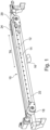
- the device comprises a belt 12, which is a metal belt 12.
- a section of the support element 14 is shown, with a support surface 14a on top.
- a channel 15 is formed in the support element 14. This channel 15 is running essentially in a longitudinal direction of the support element 14, i.e., parallel to the transport axis TA.
- the channel 15 is connected to the vacuum source 16, as shown above with respect to Figure 1 .
- a pressure below the surrounding air pressure can be generated with in the channel 15.
- the suction distributing structure 30 is in fluid connection with the channel 15.
- suction is produced in distinct ways: Where the belt 12 covers a part of the suction distributing structure 30, the suction is generated by this part of the suction distributing structure 30. As a result, the belt is pulled towards the support element 14.
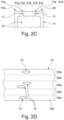
- the belt 12 is configured such that the openings 13 in a region 32a of the belt 12 are arranged above a high-resistance region 31a of the support surface 14a.
- This is a card suction region 31a, where suction can be applied to a card 11 on the transport surface 12a of the belt 12. If a card 11 is present above an opening 13, it is held down by suction; if no card 11 is present, the high-resistance properties of the suction distributing structure 30 makes sure that not too much pressure is lost.
- ink droplets of an inkjet printer may be considerably deflected by an air flow that is caused by uncovered openings 13, in particular in regions close to an edge of a card 11.
- a resulting leakage air flow through the high-resistance structure element 30a is lower than it would be for a low-resistance structure element 30b.
- the flow resistance properties of the channel 17 can be used to influence the flow resistance in addition to the properties of structure elements 30a, 30b themselves.
- the balance of the restrictions for the air flow through the channel 17 and the structures 30a, 30b defines a local pressure gradient and flow in situations with openings 13 covered by flat pieces 11, or openings 13 that are not covered and allow free air inflow.
- Figure 2D shows the belt 12 of the embodiment in a schematic top view. Only some of the openings 13 are shown for clarity.
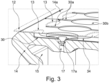
- FIG. 3 a cross-sectional view of the support element 14 and belt 12 is shown, together with parts of a perspective view. Similar elements are shown, which have already been described above with reference to Figures 2A to 2D . The following description is thus focused on elements, which have not been described before in greater detail.
- the belt 12 has openings 13.
- the suction distributing structure 30 is extending essentially along an axis Y perpendicular to the transport axis TA.
- high-resistance structure element 30a in this example formed with larger structures like rounded pads and deepenings in the support surface 14a, and low resistance structure elements 30b, in this example formed as elongated channels along the width of the belt 12.
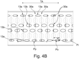
- the openings 13 have an oval form and are longer in the longitudinal direction TA than along the width Y of the belt 12.
- the openings 13 are formed with different parameters, depending on their position at the lateral edges of the belt 12 or in the middle region.
- openings 13a are configured with the same length along the transportation axis TA, but with smaller width, thus more elongated than openings 13b in the middle region.
- the openings 13a, 13b have the same length along the transport axis TA.
- the individual openings 13a, 13b extend over a larger area in the middle region of the belt 12 than at the edges.
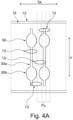
- a base 22 is shown, which serves as a carrier for the further elements of the support element 14.
- the support element modules 40 have a flat support module surface 40a, such that their assembly forms a support surface 14a of the support element 14.
- the belt 12 is transported over the support surface 14a.
- seals 44 are provided at the interfaces between support element modules 40 and the base 22, and seals 42 are provided between the support module end surface 40b at the end portions of the support element modules 40, respectively.
- three different types of support element modules 40 are provided, namely for providing a beginning section of the support element 14, where flat pieces 11 are fed onto the belt 12, a mid-section of the support element 14, over which the flat pieces 11 on the belt 12 are moved, and an end section of the support element 14, where the flat pieces 11 are removed from the belt 12.
- a support element module 40 for the mid-section may be used several times, depending on the overall length of the support element 14.
- the beginning section may be configured such that weaker suction is experienced by flat pieces 11 on a belt above the beginning section, to make sure that flat pieces 11 can be brought into a defined position before fixing the position for the transport on the belt 12.
- the support element 14 can comprise a polymer material.
- the support element of the embodiment can be configured with relatively narrow and deep channels of the suction distributing structure 30, in order to provide a high-resistance structure element 30a.
- Such a channel design can allow manufacture with lower tolerances for the air flow. For example, a tolerance of +/- 0.1 mm for the machining of a channel, a channel with 0.3 mm depth leads to ca. +/- 30 % deviation in air flow, which may affect an under-pressure that is generated by means of the channel. On the other hand, the tolerance of +/- 0.1 mm for a channel at 1.2 mm depth leads to ⁇ 10 % variation in air flow.
- flat pieces 11 with an uneven surface may pose significant challenges for a device 10 to hold a flat piece 11 by suction.
- the uneven surface may lead to a higher leakage of air into the openings 13 and a weaker sealing between the belt's transport surface 12a and the surface of the flat piece 11 is reached.
- higher suction may be necessary to hold such flat pieces 11.
- a higher suction may be needed to hold flat pieces 11 with a curvature, e.g., from embedded chips, a perforation, or with small security features or other irregularities of the surface, compared to flat pieces 11 with a perfectly flat surface in contact with the transport surface 12a of the belt 12.
- the embodiment of the device 10 may, for example, be used in a printer, in particular an inkjet printer.
- the belt 12 is extending in such a way that the flat pieces 11 on the transport surface 12a are positioned below one or several print heads, where a printing operation is performed.
Landscapes
- Engineering & Computer Science (AREA)
- Mechanical Engineering (AREA)
- Feeding Of Articles By Means Other Than Belts Or Rollers (AREA)
Claims (11)
- Vorrichtung (10) zum Befördern von flachen Teilen (11), aufweisendein Band (12) mit einer Transportfläche (12a), wobei das Band (12) entlang einer Transportachse (TA) bewegbar ist;ein Auflageelement (14) mit einer Auflagefläche (14a) zum Abstützen des Bandes (12); undeine Vakuumversorgung (16) zum Bereitstellen eines Vakuumsogs; wobeieine Saugkraftverteilungsstruktur (30) an der Auflagefläche (14a) des Auflageelements (14) mit der Vakuumversorgung (16) in Fluidverbindung steht; wobeidie Saugkraftverteilungsstruktur (30) einen Bandsaugbereich (31b) und einen Kartensaugbereich (31a) hat; wobeider Bandsaugbereich (31b) dafür ausgelegt ist, am Band (12) eine Saugwirkung bereitzustellen; undder Kartensaugbereich (31a) dafür ausgelegt ist, an flachen Teilen (11) auf der Auflagefläche (12a) des Bandes (12) eine Saugwirkung bereitzustellen; wobei die Vorrichtung (10) dadurch gekennzeichnet ist, dassdie Fluidverbindung mit der Vakuumversorgung (16) in dem Bandsaugbereich (31b) einen geringeren Strömungswiderstand hat als in dem Kartensaugbereich (31a).
- Vorrichtung (10) nach Anspruch 1,
dadurch gekennzeichnet, dass
das Band (12) Öffnungen (13) hat, die so ausgelegt sind, dass bei Betrieb der Vorrichtung (10) die Öffnungen (13) entsprechend dem Kartensaugbereich (31a) der Saugkraftverteilungsstruktur (30) angeordnet sind. - Vorrichtung (10) nach Anspruch 2,
dadurch gekennzeichnet, dass
die Öffnungen (13) so ausgelegt sind, dass sie ein Muster mit periodischen Einheiten (Pu) haben, die sich periodisch entlang der Transportachse (TA) wiederholen; wobei die periodischen Einheiten (Pu) so ausgelegt sind, dass mindestens eine Öffnung (13) der periodischen Einheit (Pu) in Fluidverbindung mit der Vakuumversorgung (16) angeordnet ist, während das Band (12) über das Transportelement (14) transportiert wird. - Vorrichtung (10) nach einem der vorhergehenden Ansprüche,
dadurch gekennzeichnet, dass
das Band (12) einen durchgehenden Bereich (32b) hat, der bei Betrieb der Vorrichtung (10) entsprechend dem Bandsaugbereich (31b) der Saugkraftverteilungsstruktur (30) angeordnet ist. - Vorrichtung (10) nach einem der vorhergehenden Ansprüche,
dadurch gekennzeichnet, dass
die Vakuumversorgung (16) einen geschlossenen Kanal (15) in dem Auflageelement (14) entlang der Transportachse (TA) aufweist. - Vorrichtung (10) nach einem der vorhergehenden Ansprüche,
dadurch gekennzeichnet, dassdie Saugkraftverteilungsstruktur (30) einen offenen Kanal (30a, 30b) mit einer Querschnittsfläche aufweist; wobeidie Querschnittsfläche in dem Kartensaugbereich (31a) kleiner ist als in dem Bandsaugbereich (31b). - Vorrichtung (10) nach einem der vorhergehenden Ansprüche,
dadurch gekennzeichnet, dass
die Saugkraftverteilungsstruktur (30) einen langgestreckten offenen Kanal (30a) in dem Kartensaugbereich (31a) aufweist. - Vorrichtung (10) nach einem der vorhergehenden Ansprüche,
dadurch gekennzeichnet, dass
die Fluidverbindung der Vakuumverteilungsstruktur (30) mit der Vakuumversorgung (16) einen ersten geschlossenen Kanal mit einem ersten Querschnitt zum Versorgen des Bandsaugbereichs (31b) und einen zweiten geschlossenen Kanal mit einem zweiten Querschnitt zum Versorgen des Kartensaugbereichs (31a) aufweist; wobei der zweite Querschnitt kleiner ist als der erste Querschnitt. - Vorrichtung (10) nach einem der vorhergehenden Ansprüche,
dadurch gekennzeichnet, dass
es sich bei den flachen Teilen (11) um Kunststoffkarten (11) handelt. - Vorrichtung (10) nach einem der vorhergehenden Ansprüche,
dadurch gekennzeichnet, dass
das Auflageelement (14) durch mindestens zwei Auflageelementmodule (40) gebildet ist. - System zum Behandeln von flachen Teilen (11), aufweisendeine Behandlungsvorrichtung, zum Beispiel einen Druckkopf; undeine Vorrichtung (10) zum Befördern der flachen Teile (11) nach einem der vorhergehenden Ansprüche; wobeidie Behandlungsvorrichtung dafür eingerichtet ist, eine Behandlung an einem flachen Teil (11) vorzunehmen, insbesondere an der Oberfläche des flachen Teils (11), das durch die Vorrichtung (10) befördert wird.
Priority Applications (2)
| Application Number | Priority Date | Filing Date | Title |
|---|---|---|---|
| EP21177050.8A EP4098595B1 (de) | 2021-06-01 | 2021-06-01 | Vorrichtung zum fördern von flachen werkstücken |
| US17/649,622 US11814260B2 (en) | 2021-06-01 | 2022-02-01 | Device for conveying flat pieces |
Applications Claiming Priority (1)
| Application Number | Priority Date | Filing Date | Title |
|---|---|---|---|
| EP21177050.8A EP4098595B1 (de) | 2021-06-01 | 2021-06-01 | Vorrichtung zum fördern von flachen werkstücken |
Publications (3)
| Publication Number | Publication Date |
|---|---|
| EP4098595A1 EP4098595A1 (de) | 2022-12-07 |
| EP4098595B1 true EP4098595B1 (de) | 2025-04-16 |
| EP4098595C0 EP4098595C0 (de) | 2025-04-16 |
Family
ID=76217737
Family Applications (1)
| Application Number | Title | Priority Date | Filing Date |
|---|---|---|---|
| EP21177050.8A Active EP4098595B1 (de) | 2021-06-01 | 2021-06-01 | Vorrichtung zum fördern von flachen werkstücken |
Country Status (2)
| Country | Link |
|---|---|
| US (1) | US11814260B2 (de) |
| EP (1) | EP4098595B1 (de) |
Family Cites Families (7)
| Publication number | Priority date | Publication date | Assignee | Title |
|---|---|---|---|---|
| DE4012948A1 (de) * | 1990-04-24 | 1991-10-31 | Roland Man Druckmasch | Vorrichtung zum foerdern von druckbogen |
| US6254092B1 (en) * | 2000-04-17 | 2001-07-03 | Hewlett-Packard Company | Controlling vacuum flow for ink-jet hard copy apparatus |
| DE102005009223A1 (de) * | 2005-03-01 | 2006-09-07 | Koenig & Bauer Ag | Saugbändertisch |
| US8413794B2 (en) * | 2010-07-29 | 2013-04-09 | Xerox Corporation | Variable vacuum belt and plenum for improved media sheet acquisition and transport |
| JP6175023B2 (ja) * | 2014-05-20 | 2017-08-02 | 京セラドキュメントソリューションズ株式会社 | 搬送装置及びインクジェット記録装置 |
| JP6882989B2 (ja) * | 2015-12-24 | 2021-06-02 | 芝浦メカトロニクス株式会社 | 錠剤印刷装置及び錠剤印刷方法 |
| US10913294B2 (en) * | 2019-05-14 | 2021-02-09 | Electronics For Imaging, Inc. | Printing systems and associated structures and methods having ink drop deflection compensation |
-
2021
- 2021-06-01 EP EP21177050.8A patent/EP4098595B1/de active Active
-
2022
- 2022-02-01 US US17/649,622 patent/US11814260B2/en active Active
Also Published As
| Publication number | Publication date |
|---|---|
| EP4098595A1 (de) | 2022-12-07 |
| US11814260B2 (en) | 2023-11-14 |
| EP4098595C0 (de) | 2025-04-16 |
| US20220380154A1 (en) | 2022-12-01 |
Similar Documents
| Publication | Publication Date | Title |
|---|---|---|
| SK500192023A3 (sk) | Zariadenie na výrobu laminovaného jadra motora a spôsob jeho výroby | |
| KR101629776B1 (ko) | 웹 부상 반송장치 및 그 제조방법 | |
| US12194736B2 (en) | Printing systems and associated structures and methods having ink drop deflection compensation | |
| JP7036835B2 (ja) | 段ボール箱の分割装置及び段ボール箱の製造装置 | |
| TW201509540A (zh) | 用於原子層沈積之噴射頭 | |
| EP4098595B1 (de) | Vorrichtung zum fördern von flachen werkstücken | |
| KR20160038534A (ko) | 슬롯 다이 및 이를 이용한 유기태양전지의 제조방법 | |
| US11453026B2 (en) | Laminated slot die assembly | |
| EP2287098B1 (de) | Papierblattförderer und papierblattfördersystem | |
| KR101894558B1 (ko) | 모터 코어 제조용 냉각 장치 | |
| KR101473398B1 (ko) | 기재 플로팅 방법 및 장치 | |
| WO2016102771A1 (en) | Nozzle head and apparatus for coating substrate surface | |
| CN114126880A (zh) | 用于对型材体,尤其是封边带进行印刷的装置和方法 | |
| EP2186630A1 (de) | Vorrichtung und verfahren zur herstellung eines flächengebildes mit korden | |
| JP2009067055A (ja) | サーマルプリンタを用いた印刷装置 | |
| JP3843569B2 (ja) | 斜め穴加工装置 | |
| CN211593227U (zh) | 真空架及包含其的真空输送带机构 | |
| JP7330835B2 (ja) | 被印刷物用の搬送装置および印刷機 | |
| JP2005199110A (ja) | 塗布装置 | |
| CN100374000C (zh) | 在小型元件载体的弹性遮罩中形成尺寸精确的狭槽的方法 | |
| KR101474129B1 (ko) | 롤투롤 인쇄 장치에서의 공기의 분사와 흡입을 이용한 필름 유도 장치 | |
| US20100206193A1 (en) | Printing sleeve | |
| CN210283311U (zh) | 带敷设设备 | |
| KR20170037176A (ko) | 건조형 슬롯 다이 및 이를 이용한 유기태양전지의 제조방법 | |
| CN120382660B (zh) | 一种高精度模切贴合装置及自动贴合方法 |
Legal Events
| Date | Code | Title | Description |
|---|---|---|---|
| PUAI | Public reference made under article 153(3) epc to a published international application that has entered the european phase |
Free format text: ORIGINAL CODE: 0009012 |
|
| STAA | Information on the status of an ep patent application or granted ep patent |
Free format text: STATUS: THE APPLICATION HAS BEEN PUBLISHED |
|
| AK | Designated contracting states |
Kind code of ref document: A1 Designated state(s): AL AT BE BG CH CY CZ DE DK EE ES FI FR GB GR HR HU IE IS IT LI LT LU LV MC MK MT NL NO PL PT RO RS SE SI SK SM TR |
|
| STAA | Information on the status of an ep patent application or granted ep patent |
Free format text: STATUS: REQUEST FOR EXAMINATION WAS MADE |
|
| 17P | Request for examination filed |
Effective date: 20230522 |
|
| RBV | Designated contracting states (corrected) |
Designated state(s): AL AT BE BG CH CY CZ DE DK EE ES FI FR GB GR HR HU IE IS IT LI LT LU LV MC MK MT NL NO PL PT RO RS SE SI SK SM TR |
|
| P01 | Opt-out of the competence of the unified patent court (upc) registered |
Effective date: 20230627 |
|
| GRAP | Despatch of communication of intention to grant a patent |
Free format text: ORIGINAL CODE: EPIDOSNIGR1 |
|
| STAA | Information on the status of an ep patent application or granted ep patent |
Free format text: STATUS: GRANT OF PATENT IS INTENDED |
|
| RIC1 | Information provided on ipc code assigned before grant |
Ipc: B65H 5/22 20060101AFI20241025BHEP |
|
| INTG | Intention to grant announced |
Effective date: 20241121 |
|
| GRAS | Grant fee paid |
Free format text: ORIGINAL CODE: EPIDOSNIGR3 |
|
| GRAA | (expected) grant |
Free format text: ORIGINAL CODE: 0009210 |
|
| STAA | Information on the status of an ep patent application or granted ep patent |
Free format text: STATUS: THE PATENT HAS BEEN GRANTED |
|
| AK | Designated contracting states |
Kind code of ref document: B1 Designated state(s): AL AT BE BG CH CY CZ DE DK EE ES FI FR GB GR HR HU IE IS IT LI LT LU LV MC MK MT NL NO PL PT RO RS SE SI SK SM TR |
|
| REG | Reference to a national code |
Ref country code: GB Ref legal event code: FG4D |
|
| REG | Reference to a national code |
Ref country code: CH Ref legal event code: EP Ref country code: DE Ref legal event code: R096 Ref document number: 602021029124 Country of ref document: DE |
|
| REG | Reference to a national code |
Ref country code: IE Ref legal event code: FG4D |
|
| U01 | Request for unitary effect filed |
Effective date: 20250416 |
|
| P04 | Withdrawal of opt-out of the competence of the unified patent court (upc) registered |
Free format text: CASE NUMBER: APP_19007/2025 Effective date: 20250421 |
|
| U07 | Unitary effect registered |
Designated state(s): AT BE BG DE DK EE FI FR IT LT LU LV MT NL PT RO SE SI Effective date: 20250424 |
|
| U20 | Renewal fee for the european patent with unitary effect paid |
Year of fee payment: 5 Effective date: 20250522 |
|
| PGFP | Annual fee paid to national office [announced via postgrant information from national office to epo] |
Ref country code: GB Payment date: 20250508 Year of fee payment: 5 |
|
| PG25 | Lapsed in a contracting state [announced via postgrant information from national office to epo] |
Ref country code: ES Free format text: LAPSE BECAUSE OF FAILURE TO SUBMIT A TRANSLATION OF THE DESCRIPTION OR TO PAY THE FEE WITHIN THE PRESCRIBED TIME-LIMIT Effective date: 20250416 |
|
| PG25 | Lapsed in a contracting state [announced via postgrant information from national office to epo] |
Ref country code: GR Free format text: LAPSE BECAUSE OF FAILURE TO SUBMIT A TRANSLATION OF THE DESCRIPTION OR TO PAY THE FEE WITHIN THE PRESCRIBED TIME-LIMIT Effective date: 20250717 Ref country code: NO Free format text: LAPSE BECAUSE OF FAILURE TO SUBMIT A TRANSLATION OF THE DESCRIPTION OR TO PAY THE FEE WITHIN THE PRESCRIBED TIME-LIMIT Effective date: 20250716 |
|
| PG25 | Lapsed in a contracting state [announced via postgrant information from national office to epo] |
Ref country code: PL Free format text: LAPSE BECAUSE OF FAILURE TO SUBMIT A TRANSLATION OF THE DESCRIPTION OR TO PAY THE FEE WITHIN THE PRESCRIBED TIME-LIMIT Effective date: 20250416 |
|
| PG25 | Lapsed in a contracting state [announced via postgrant information from national office to epo] |
Ref country code: HR Free format text: LAPSE BECAUSE OF FAILURE TO SUBMIT A TRANSLATION OF THE DESCRIPTION OR TO PAY THE FEE WITHIN THE PRESCRIBED TIME-LIMIT Effective date: 20250416 |
|
| PG25 | Lapsed in a contracting state [announced via postgrant information from national office to epo] |
Ref country code: RS Free format text: LAPSE BECAUSE OF FAILURE TO SUBMIT A TRANSLATION OF THE DESCRIPTION OR TO PAY THE FEE WITHIN THE PRESCRIBED TIME-LIMIT Effective date: 20250716 |
|
| PG25 | Lapsed in a contracting state [announced via postgrant information from national office to epo] |
Ref country code: IS Free format text: LAPSE BECAUSE OF FAILURE TO SUBMIT A TRANSLATION OF THE DESCRIPTION OR TO PAY THE FEE WITHIN THE PRESCRIBED TIME-LIMIT Effective date: 20250816 |