EP4098528B1 - Serrure en châssis - Google Patents
Serrure en châssis Download PDFInfo
- Publication number
- EP4098528B1 EP4098528B1 EP22174559.9A EP22174559A EP4098528B1 EP 4098528 B1 EP4098528 B1 EP 4098528B1 EP 22174559 A EP22174559 A EP 22174559A EP 4098528 B1 EP4098528 B1 EP 4098528B1
- Authority
- EP
- European Patent Office
- Prior art keywords
- web
- bracket
- circular path
- rotary
- rotary hoop
- Prior art date
- Legal status (The legal status is an assumption and is not a legal conclusion. Google has not performed a legal analysis and makes no representation as to the accuracy of the status listed.)
- Active
Links
Images

Classifications
-
- B—PERFORMING OPERATIONS; TRANSPORTING
- B62—LAND VEHICLES FOR TRAVELLING OTHERWISE THAN ON RAILS
- B62H—CYCLE STANDS; SUPPORTS OR HOLDERS FOR PARKING OR STORING CYCLES; APPLIANCES PREVENTING OR INDICATING UNAUTHORIZED USE OR THEFT OF CYCLES; LOCKS INTEGRAL WITH CYCLES; DEVICES FOR LEARNING TO RIDE CYCLES
- B62H5/00—Appliances preventing or indicating unauthorised use or theft of cycles; Locks integral with cycles
- B62H5/14—Appliances preventing or indicating unauthorised use or theft of cycles; Locks integral with cycles preventing wheel rotation
- B62H5/147—Appliances preventing or indicating unauthorised use or theft of cycles; Locks integral with cycles preventing wheel rotation by means of circular bolts
-
- B—PERFORMING OPERATIONS; TRANSPORTING
- B62—LAND VEHICLES FOR TRAVELLING OTHERWISE THAN ON RAILS
- B62H—CYCLE STANDS; SUPPORTS OR HOLDERS FOR PARKING OR STORING CYCLES; APPLIANCES PREVENTING OR INDICATING UNAUTHORIZED USE OR THEFT OF CYCLES; LOCKS INTEGRAL WITH CYCLES; DEVICES FOR LEARNING TO RIDE CYCLES
- B62H5/00—Appliances preventing or indicating unauthorised use or theft of cycles; Locks integral with cycles
- B62H5/14—Appliances preventing or indicating unauthorised use or theft of cycles; Locks integral with cycles preventing wheel rotation
- B62H5/142—Appliances preventing or indicating unauthorised use or theft of cycles; Locks integral with cycles preventing wheel rotation by means of pivoting, or pivoting and sliding bolts
Definitions
- the invention relates to a frame lock for a two-wheeler.
- Frame locks typically differ from mobile bicycle locks in that they are firmly and usually permanently connected to the frame of the bicycle, for example, screwed to the frame.
- the frame lock is arranged in such a way that a shackle of the frame lock can be selectively adjusted to a position in which it engages between the spokes of a wheel of the bicycle, thus preventing the bicycle from being ridden in this way.
- the shackle is expediently secured by a bolt of the frame lock, which, at least ideally, can only be adjusted via a locking cylinder or other locking device of the frame lock, for the operation of which the user must have a secret key, such as a key.
- Typical designs for the shackle include, on the one hand, a swivel shackle with a straight profile and, on the other hand, a rotating shackle with a circular arc.
- a generic frame lock with a rotating shackle is made, for example, of DE 10 2018 121 248 A1 known.
- a frame lock can comprise a lock body with a bolt and a rotating bracket which extends along a circular path and is adjustable relative to the lock body along the circular path between an open position in which it releases a wheel of the bicycle for rotation and a closed position in which it locks the wheel against rotation, wherein the rotating bracket has a locking structure with a stop section, wherein the bolt is adjustable between an unlocking position and a locking position and wherein, when the rotary bracket is in its closed position and the bolt is in its locking position, the bolt engages behind the stop section and thereby locks the rotary bracket against being adjusted into the open position.
- the stability of the shackle is a crucial factor for the reliability of the frame lock. To ensure that the frame lock cannot be forced open, the shackle must be particularly strong. At the same time, the aim is to manufacture the shackle as cost-effectively and as fully automated as possible.
- a pivoting shackle for a frame lock can, for example, be made from a bar stock, in particular a metal wire, which is bent into a circular arc.
- a recess can be machined into this bar stock, for example, by punching or milling.
- a side wall of this recess can form the stop section.
- machining has the disadvantage that the machined material is weakened as a result, since fibers running lengthwise through the bar stock are interrupted. In particular, this can result in distortion during subsequent hardening of the pivoting shackle, which can even lead to breakage during subsequent straightening.
- the frame lock according to the invention for a two-wheeler comprises a lock body with a bolt and a rotating bracket which extends along a circular path and is adjustable relative to the lock body along the circular path between an open position in which it releases a wheel of the two-wheeler for rotation and a closed position in which it locks the wheel against rotation.
- the rotating bracket is preferably formed from a rod material, in particular a metal wire, such as steel wire, wherein the rod material preferably has a constant cross-section.
- the diameter of the circular path can, for example, be in the range between 10 cm and 15 cm, for example approximately 13 cm.
- the rotating bracket can have a diameter on the order of a few millimeters to a few centimeters.
- the diameter of the cross-section can be, at least on average, approximately 8 or 9 mm.
- the rotating bracket Due to its extension along the circular path, the rotating bracket has a circular arc shape that extends over a certain partial region of the circularly closed circular path, for example over an angular range of at least 200° and/or at most 250°, preferably of at least 210° and/or at most 240°, in particular of approximately 225° or 230°.
- the rotary bracket is adjustable between the open and closed positions, the rotary bracket can be adjusted from the open position in a closing direction to the closed position and vice versa from the closed position in an opening direction opposite to the closing direction to the open position.
- this does not exclude the possibility of the rotary bracket being adjusted in other ways, in particular in the closing direction beyond the closed position. and/or in the opening direction beyond the open position.
- Adjusting the rotating bracket corresponds to rotating the rotating bracket around an axis of rotation that runs through the center of the circular path and is perpendicular to a plane in which the circular path lies.
- the rotating yoke In the closed position, the rotating yoke preferably extends out of the lock body, in particular out of the aforementioned housing of the lock body, and then at least with one free end back into the lock body, in particular into the housing, so that the lock body and the rotating yoke preferably form a closed ring in the closed position. In this way, the respective wheel can be locked against rotation particularly reliably.
- the rotating yoke In the open position, however, the rotating yoke extends out of the lock body, but not back into it, or is at least almost completely accommodated in the lock body, in particular in the housing.
- the stop section is preferably, but not necessarily, designed as a stop surface, i.e., flat.
- the stop section can also be formed by an edge or a contour of the locking structure.
- the locking structure can be designed in many different ways.
- One fundamentally conceivable, but not claimed, way is for the locking structure to comprise a notch or recess in the rotating bracket, wherein the notch or recess can extend, in particular, radially from the outside to the inside of the rotating bracket with respect to the center of the circular path.
- the stop section can be designed as a side wall of such a notch or recess.
- the locking structure can have a plurality of stop sections, each of which can be engaged behind by the latch to secure different positions of the rotary bracket against departure from the respective position in at least one adjustment direction.
- Several of the stop sections can serve to secure the same position, whether with respect to the same adjustment direction or opposite adjustment directions.
- the aforementioned engagement of the locking bar behind the stop section is to be understood as referring to the adjustment of the rotary bracket to be locked.
- the locking bar engages transversely to the circular path in a movement path of the locking bar that the locking bar would follow if the locking bar were in its unlocked position and the rotary bracket were adjusted along the circular path in the direction of adjustment to be locked.
- the bolt When the rotary bracket is in its closed position and the bolt is in its locking position, the bolt preferably rests against the stop section or at least has a small distance, for example of less than 1 mm, in particular of a few hundred micrometers, from the stop section. This advantageously prevents the pivoting bracket from leaving the closed position in the direction of the open position.
- the bolt can also be spaced a greater distance from the stop section, so that the pivoting bracket can be adjusted from the closed position by a distance corresponding to this distance, but is in any case prevented from reaching a position in which the pivoting bracket would no longer reliably lock the wheel against rotation.
- the locking structure comprises at least one web which protrudes from the rotating bracket, in particular transversely to the longitudinal extent of the rotating bracket, and which has the stop section.
- the entire web need not protrude from the pivot bracket; it is sufficient for the web to protrude partially from the pivot bracket.
- a portion of the web may also extend into the pivot bracket, particularly transversely to the longitudinal extent of the pivot bracket.
- the portion of the web protruding from the pivot bracket may, in particular, represent a convex structure relative to its surroundings.
- the rotating bracket may have further sections with the same cross-section.
- all sections located along the circular path between two webs projecting from the rotating bracket preferably all web-free sections of the rotating bracket (possibly with the exception of end sections at both ends of the longitudinal extension of the rotating bracket) have the same cross-section.
- the web has two mutually opposite parallel side surfaces which extend at least substantially along the circular path, wherein the stop section is formed by an end face of the web which connects the side surfaces and is oriented at least substantially perpendicular to the circular path.
- the two side surfaces are preferably oriented parallel to the direction in which the web protrudes from the pivot bracket.
- the webs can extend along the circular path.
- the side surfaces can therefore have a curved course corresponding to the circular path.
- relatively short webs in particular can also have a straight course tangential to the circular path.
- Such a web with two parallel side surfaces can be formed comparatively easily and cost-effectively by cold forming.
- an outer portion of the section can be pressed, for example between a punch and a support, from opposite directions such that the material of this portion is formed into a web that at least partially protrudes outwards perpendicular to these directions.
- the two side surfaces of the web are thus aligned perpendicular to the two opposite directions from which the portion is pressed.
- a transition between the end face forming the stop section and an outer side of the web which connects the two side surfaces and is oriented away from the rotating bracket, has a radius of curvature of at most 1 mm, preferably at most 0.5 mm, in particular at most 0.3 mm, and/or at most 1.5%, preferably at most 1%, in particular at most 0.5%, of the radius of the circular path.
- the outer side can be one of the edge sides of the web mentioned. Due to the orientation of the outer side pointing away from the rotating bracket, the end face forming the stop section and the outer side can in particular be aligned at least substantially perpendicular to one another.
- the side surfaces of the web extend relative to a section of the rotary bracket adjacent to the web along the circular path, preferably relative to sections of the rotary bracket adjacent to the web on both sides along the circular path, both further both out of the pivot bracket and further into the pivot bracket, particularly relative to a surface of the respective section that faces outward in the direction of the web's protrusion and runs along the circular path.
- the webs can not only protrude from the pivot bracket, but also at least partially protrude into it, thus being particularly securely anchored to the pivot bracket.
- a recess formed in the pivot bracket adjoins each of the two side surfaces of the web.
- the recesses can, in particular, each be formed as a concave structure in the pivot bracket.
- the recesses can adjoin the respective side surface perpendicularly to the latter.
- a part of the respective side surface namely, in particular, a part of the respective side surface extending into the pivot bracket as explained above, can form a wall of the respective recess.
- Both recesses preferably have a constant cross-section, in particular the same, with respect to a direction perpendicular to the side surfaces.
- the two recesses can also be regarded as a single recess with a constant cross-section, which is divided in two, in particular precisely halved, by the web.
- the recesses can, in addition to the webs, contribute to locking the rotary bracket.
- the bolt not only engages behind the stop surface of the web, but also engages in at least one of the two recesses, preferably in both, when the rotary bracket is in its closed position and the bolt is in its locking position.
- the bolt preferably engages in a respective recess in such a way that adjustment of the rotary bracket along the circular path in at least one direction is blocked.
- the web can protrude from the rotating bracket in a direction perpendicular to the plane of the circular path.
- the web then protrudes axially from the rotating bracket, i.e., parallel to the axis of rotation extending through the center of the circular path and oriented perpendicular to the plane of the circular path.
- the web is preferably oriented radially outward.
- the material from which the swivel bracket is formed can have main fibers that run in a central region of the swivel bracket with respect to a direction perpendicular to the circular path and are important for the stability of the swivel bracket.
- main fibers that run in a central region of the swivel bracket with respect to a direction perpendicular to the circular path and are important for the stability of the swivel bracket.
- the locking structure of the swivel bracket comprises at least a pair of two webs arranged at the same position along the circular path and protruding in opposite directions from the swivel bracket (as will be explained further below), which then preferably protrude axially opposite one another from the swivel bracket.
- the said web that projects from the pivoting bracket and whose stop section is engaged behind by the bolt when the pivoting bracket is in its closed position and the bolt is in its locking position can also be referred to as the first web, without this designation being intended as an indication of a specific minimum, maximum or total number or of a specific order of priority or spatial sequence. which may include several webs projecting from the rotating bracket.
- the locking structure comprises a plurality of webs protruding from the rotary bracket, each of which has a stop section and can also be designed in particular according to one of the ways described for the first web, wherein the latch, when the rotary bracket is in a specific position and the latch is in its locking position, engages behind the stop section of a respective one of the webs and thereby locks the rotary bracket against adjustment from the specific position, at least in one of the two opposite adjustment directions along the circular path.
- the latch engages behind the respective stop section, in particular with regard to the adjustment direction to be locked.
- the specific position can be the closed position for one or more of the bars.
- the closed position of the pivot bracket not only the stop section of the first bar can be engaged behind by the bolt in its locked position, but also the (respective) stop section of one or more of the several bars protruding from the pivot bracket. In this way, the closed position can be secured particularly reliably by means of several bars protruding from the pivot bracket.
- the specific position for one or more of the protruding webs of the pivot bracket can also be a position of the pivot bracket other than the closed position.
- the pivot bracket can not only be locked in its closed position against adjustment (in at least one direction along the circular path) by means of the bolt, but also in one or more other positions, especially in its open position.
- the locking structure can comprise a further web protruding from the rotary bracket, which has a stop section and can also be designed in particular according to one of the ways described for the first web, wherein the bolt, when the rotary bracket is in its open position and the bolt is in its locking position, engages behind the stop section of this further web (with respect to the adjustment direction to be blocked) and thereby blocks the rotary bracket from being adjusted from the open position.
- the rotary bracket is then locked, in particular, at least against reaching the closed position, but preferably already against leaving the open position in the direction of the closed position.
- This additional web may be one of the aforementioned several webs protruding from the pivot bracket.
- this additional web may also be referred to as a second web, without this designation being understood as an indication of a specific minimum, maximum, or total number, or of a specific ranking or spatial sequence of the possibly several webs protruding from the pivot bracket.
- the same locking mechanism that locks the swivel bar in the closed position can also be used to prevent it from being moved from the open position. This can be useful to ensure that the swivel bar cannot be accidentally moved in the closing direction, especially while riding the bicycle, and thus interfere with the wheel.
- the locking structure can comprise a further web protruding from the rotary bracket, which has a stop section and can also be designed in particular in one of the ways described for the first web, wherein the bolt, when the rotary bracket is in its closed position and the bolt is in its locking position, engages behind the stop section of this further web (with respect to the adjustment direction to be blocked) and thereby blocks the rotary bracket against adjustment from the closed position in the direction away from the open position, i.e. in the closing direction beyond the closed position.
- the rotary bracket can already be blocked against leaving the closed position in this direction.
- This additional web may be one of the aforementioned several webs protruding from the pivoting bracket.
- this additional web may also be referred to as a third web, without this designation being understood as an indication of a specific minimum, maximum, or total number, or of a specific ranking or spatial sequence of the possibly several webs protruding from the pivoting bracket.
- the presence of the third web does not require the presence of the aforementioned second web.
- the pivot shackle can be secured in its closed position not only against adjustment in the opening direction, but also against adjustment in the closing direction.
- Such an additional security feature can be useful to ensure that the pivot shackle cannot be forcibly torn out of the lock body in the closing direction.
- At least two of the Webs have the same position along the circular path and protrude from the rotary bracket in opposite directions, in particular diametrically opposite one another with respect to a center point of the cross section of the rotary bracket, wherein the latch is designed such that, when the rotary bracket is in the respective position to be locked and the latch is in its locking position, it engages behind both the stop section of one of the webs and the stop section of the other of the webs.
- their two stop sections can have the same position along the circular path.
- their stop sections lie in the same plane.
- the respective position to be locked may in particular be the above-mentioned specific position of the rotary bracket, in which the rotary bracket is locked against being adjusted from this position by engaging behind the stop section of a respective one of the two webs and which may in particular be the closed position or the open position of the rotary bracket.
- the bolt can in particular be fork-shaped with a semicircular contour enclosing the rotary bracket, which opens into two arms which, in the locking position of the bolt, engage behind the stop section of each of the two webs.
- the side surfaces can point in the direction corresponding to the movement of the bolt from its locking position to its unlocking position.
- the bolt can be pre-tensioned in the opposite direction, i.e., from the unlocking position to its locking position, and, after the bolt has been moved to release a locked position of the pivoting bracket into its unlocking position, can slide along the track formed by the side surfaces, pre-tensioned against the track, while the pivoting bracket is being adjusted. In this way, the bolt can be held in its unlocking position, or at least in a position that does not lock the pivoting bracket, by means of the bar during the movement of the pivoting bracket.
- the strip is attached to the swivel bracket in a form-fitting manner, in particular by snapping into place.
- the strip can form a form-fitting connection with at least one of the possibly several webs projecting from the swivel bracket.
- the strip can be caught between the two webs, between which it at least extends, in such a way that It must be clearly fixed relative to the rotating bracket along the circular path, i.e., it cannot be moved along the circular path relative to the rotating bracket (but only together with it).
- the bar is positively attached to the rotating bracket in any spatial direction.
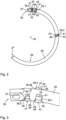
- the frame lock 11 comprises a lock body 13 with a housing 15 that is at least substantially C-shaped, wherein a central section of the C-shape is widened in a cuboid shape and the two remaining sections form a first leg 17 and a second leg 19 of the lock body 13, which extend from corners of the cuboid shape.
- a non-visible locking device in the form of a locking cylinder and a bolt 21 coupled to the locking device (cf. Figs. 6 and 7 ).
- the locking device can only be normally operated using a key 23 assigned to the locking device.
- the bolt 21 is coupled to the locking device in such a way that it can be adjusted between an unlocked position and a locked position by actuating the locking device using the key 23.
- the frame lock 11 further comprises a rotating shackle 25, which extends along a circular path and is at least partially received in the housing 15, namely in a rotating shackle receptacle that extends through the first leg 17 and into the cuboid-shaped central section of the lock body 13.
- the rotating shackle 25 is mounted relative to the lock body 13 such that it can be adjusted along its longitudinal extent, i.e., along the aforementioned circular path, between an open position and a closed position.
- the rotating shackle 25 has a constant cross-section in sections, which is circular in the example shown, but could in principle also have a different shape, for example, that of a regular polygon.
- the sections having the constant cross-section together form a (far) predominant part, for example, over 80%, in particular over 90%, of the longitudinal extent of the rotating shackle 25.
- the rotating bracket 25 protrudes with a free end 27 from the first leg 17 and extends to the second leg 19 and into it with the free end 27, so that it connects the two legs 17, 19 and the lock body 13 and the rotating bracket 25 thereby form a closed ring.
- the rotating bracket 25 can, with appropriate
- the frame lock 11 is mounted on the frame of a bicycle (not shown)
- it can engage a wheel of the bicycle between its spokes, thus locking the wheel against rotation.
- the section of the rotating bracket 25 that is arranged outside the housing 15 in the closed position forms a blocking section 29 of the rotating bracket 25, which has the aforementioned circular cross-section throughout.
- the blocking section 29 extends along the aforementioned circular path over an angular range of approximately 60°.
- the rotating bracket 25 In the open position, however, the rotating bracket 25 is completely housed within the housing 15 or protrudes only slightly with its free end 27 from the first leg 17 of the housing 15, so that a free space remains between the two legs 17, 19, within which the spokes of the wheel can be moved between the legs 17, 19 of the frame lock 11. Thus, in its open position, the rotating bracket 25 releases the wheel of the bicycle for rotation.
- the rotating bracket 25 can be moved manually by means of a handle 31 from the open position to the closed position and vice versa, from the closed position back to the open position along the circular path, which corresponds to a rotation of the rotating bracket 25 about the center point M of the circular path.
- the handle 31 is coupled to the rotating bracket 25 and extends perpendicular to the plane of the circular path along which the rotating bracket 25 extends, through a slot 33 formed in the first leg 17.
- the slot 33 has a circular arc-shaped profile, wherein the circular arc shape of the slot 33 corresponds to the profile of the circular path, in particular is coaxial to the circular path, i.e. has the same center point M.
- Fig. 1 shows the frame lock 11 in a side view, perpendicular to the circular path along which the rotating bracket 25 of the frame lock 11 extends.
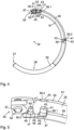
- Fig. 2 and 4 the direction of view is exactly the opposite.
- FIG. 2 The rotating shackle 25 of the frame lock 11 is shown separately. It can be seen that the free end 27 of the rotating shackle 25 has a conical chamfer. The opposite end of the rotating shackle 25 is attached to the lock body 13. This end thus forms a coupled end 35 of the rotating shackle 25. At the coupled end 35, the rotating shackle 25 is flattened on both sides perpendicular to the plane of the circular path and, among other things, for coupling to the lock body 13, has a hole 37 extending perpendicular to the plane of the circular path through the rotating shackle 25.
- the rotary bracket 25 has a locking structure comprising a plurality of webs 39.
- Each of these webs 39 protrudes at least partially from the rotary bracket 25 perpendicular to the plane of the circular path.
- the webs 39 each protrude beyond the aforementioned circular cross-section, which is particularly present in sections of the rotary bracket 25 adjacent to the respective web 39 along the circular path.
- the webs 39 thus extend outward beyond an outer contour of this cross-section.
- the webs 39 are formed by cold forming.
- the bar material from which the swivel bracket 25 is formed and which has the aforementioned constant cross-section is clamped between a punch and a support either before being bent into the circular arc shape (i.e., with a still straight profile) or with the arc already in the shape of a circle.
- a groove is formed in the direction in which the web 39 is to protrude.
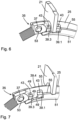
- the bolt 21 and the rotary bracket 25 are arranged relative to one another in such a way that the bolt 21, in its locked position, is at least partially located in the path of movement of the webs 39, which the webs 39 would traverse unhindered when the rotary bracket 25 were adjusted along the circular path.
- the bolt 21 in its locked position, depending on the direction of adjustment of the rotary bracket 25, it engages behind one of the end faces 45 of the web 39 closest in this direction.
- this end face 45 consequently strikes the bolt 21, so that the rotary bracket 25 is thereby locked against further adjustment in this direction.
- the first web 39.1 is arranged along the longitudinal extent of the rotary bracket 25 in such a way that the bolt 21, when the rotary bracket 25 is in its closed position and the bolt 21 is adjusted to its locking position, engages in the movement path next to the first web 39.1.
- the movement along the circular path in an opening direction in which the rotary bracket 25 can basically be adjusted from its closed position to its open position (in Fig. 2 and 4 the opening direction corresponds to the counterclockwise direction), then forms a stop section 49 arranged adjacent to the bolt 21, so that the rotary bracket 25 is blocked by the interaction of the bolt 21 with this stop section 49 against leaving the closed position in the opening direction.
- the second web 39.2 is arranged along the longitudinal extent of the rotary bracket 25 in such a way that the bolt 21, when the rotary bracket 25 is in its open position and the bolt 21 is adjusted to its locking position, engages in the movement path next to the second web 39.2.
- the end face 45 of the second web 39.2 pointing in the opposite direction ie the closing direction corresponds to the clockwise direction
- the stop section 49 arranged adjacent to the bolt 21, so that the rotary bracket 25 is blocked by the interaction of the bolt 21 with this stop section 49 against leaving the open position in the closing direction.
- the third web 39.3 is arranged along the longitudinal extent of the pivot bracket 25 such that, when the pivot bracket 25 is in its closed position and the latch 21 is moved into its locking position, the latch 21 engages in the movement path of the third web 39.3 next to the third web 39.3.
- the end face 45 of the third web 39.2, which faces in the closing direction along the circular path, then forms a stop section 49 arranged adjacent to the latch 21, so that the pivot bracket 25 is blocked from being moved in the closing direction beyond the closed position by the interaction of the latch 21 with this stop section 49.
- the bolt 21 engages in its locking position between the first web 39.1 and the third web 39.3, in particular between the stop sections 49 of these two webs 39.1 and 39.3 (see also Fig. 6 ), so that the rotary bracket 25 is locked in both adjustment directions along the circular path (opening and closing direction). Due to the additional locking in the closing direction, the rotary bracket 25 is secured against being torn out of the lock body 13 in its closed position.
- the rotating bracket 25 has a fourth web 39.4, which is inserted into the Fig. 3 and 5 can be seen and has the same position along the circular path as the first web 39.1, but in the opposite direction, ie in the Fig. 2 and 4 perpendicular to the image plane into the image plane, protruding from the rotating bracket 25. Furthermore, the rotating bracket 25 has a fifth web 39.5, which has the same position along the circular path as the second web 39.2, but protrudes in the opposite direction from the rotating bracket 25. The fifth web 39.5 is in Fig. 1 can be seen through the slot 33 for the handle 31.
- the fourth web 39.4 and the fifth web 39.5 are not only designed in a largely identical manner (except for the opposite orientation) to the first web 39.1 and the second web 39.2, respectively, but also have the same function, namely, in cooperation with the bolt 21, to lock the rotary bracket 25 against leaving the closed position in the opening direction or the open position in the closing direction, so that the reliability of locking the rotary bracket 25 in a respective position is further improved by the fourth web 39.4 and the fifth web 39.5.
- the frame lock 11 further comprises a strip 51 made of plastic, which is arranged on the rotating bracket 25 and in particular in the Fig. 4 to 7 can be seen.
- the strip 51 engages with a pin 53 formed on the strip 51 into the hole 37 at the coupled end 35 of the rotary bracket 25 and extends from there over a large part of the longitudinal extent of the rotary bracket 25, in particular at least substantially up to the aforementioned blocking section 29.
- the strip 51 has, at least in sections, namely in particular in the section between the first web 39.1 and the second web 39.2, a substantially C-shaped cross-section and thus covers the rotary bracket 25. with respect to the circular path both radially inwards and in the two axial directions, i.e. directions perpendicular to the plane of the circular path.
- a portion of the strip 51 rests against the surface of the pivot bracket 25 along an outer contour that extends from the first web 39.1, following a circular path, to the second web 39.2.
- the height of the strip 51 i.e., the radial extension of the strip 51 to a center point of the cross-section of the pivot bracket) corresponds to the extent by which the first web 39.1 and the second web 39.2 protrude from the pivot bracket 25, so that the strip 51 fills the area between the two webs 39.1 and 39.2.
- a side surface 55 of the strip 51 which delimits the strip 51 in this area in the circumferential direction around the rotating bracket 25, is aligned with the two side surfaces 43 of the two webs 39.1 and 39.2, which point radially outwards with respect to the center point M of the circular path, so that the three side surfaces 49, 55 form a substantially continuous path.
- the strip 51 is (apart from the end where it is coupled to the coupled end 35 of the rotary bracket 25 via the pin 53) symmetrical with respect to a plane parallel to the plane of the circular path. Therefore, the strip 51 fills the image plane of the Fig. 4 and therefore in Fig. 4 not visible part also the area between the fourth web 39.4 and the fifth web 39.5 and has a side surface 55 which delimits the strip 51 in this area in the circumferential direction and which is aligned with the two side surfaces 43 of the two webs 39.4 and 39.5 which point radially outwards with respect to the center point M of the circular path and thereby forms an essentially continuous path with them (cf. Fig. 5 ).
- the strip 51 Due to the extension of the strip 51 on the one hand from the first web 39.1 to the second web 39.2 and on the other hand from the fourth web 39.4 to the fifth web 39.5, the strip 51 forms a positive connection with these webs 39.
- the strip 51 can be fastened to the rotating bracket 25 in a snap-in manner, i.e. by an elastically reversible positive connection, and can be trapped between the webs 39, so that it cannot move along the circular path relative to the rotating bracket 25. In this way, the material structure of the rotating bracket 25 is not impaired by the fastening of the strip 51 and the handle 31 provided thereon to the rotating bracket 25.
- the strip 51 has a fastening projection formed integrally with the strip 51, namely molded onto the strip 51.
- This fastening projection extends perpendicular to the circular path and thus perpendicular to the image plane of the Fig. 4 into the image plane and is therefore not visible.
- Figs. 6 and 7 illustrate the interaction of the bolt 21 with the rotating bracket 25, in particular with its webs 39, and with the bar 51.
- FIG. 6 A state is shown in which the rotating bracket 25 is in its closed position and the bolt 21 is in its locking position.
- the bolt 21 engages behind both the stop section 49 of the first web 39.1 and the stop section 49 of the oppositely oriented fourth web 39.4 (cf. Fig. 7 ) with respect to an adjustment of the rotary bracket 25 in the opening direction, i.e., toward the open position, and therefore blocks such adjustment.
- the bolt 21 also engages behind the stop section 49 of the third web 39.3 (cf. Fig. 7 ) with regard to adjustment in the closing direction and thus also blocks such adjustment.
- the bolt 21 can simultaneously interact with the webs 39.1 and 39.3 projecting from the rotating bracket 25 in a direction perpendicular to the plane of the circular path and the web 39.4 projecting from the rotating bracket 25 in the opposite direction is made possible by the fact that the bolt 21 is fork-shaped and has a contour that surrounds the rotary bracket 25 according to its cross-section, i.e., semicircular in the example shown.
- the latch 21 has two arms, into which the contour opens on one side and the other, respectively, and which can thus interact with one or more respective webs 39 on opposite sides of the rotary bracket 25 (axially with respect to the circular path), in particular can engage behind a stop section 49 of the respective web 39.
- the latch 21 can slide on both sides along the two continuous paths formed by one side surface 55 of the strip 51 and the side surfaces 43 of the first web 39.1 and second web 39.2 or by the other side surface 55 of the strip 51 and the side surfaces 43 of the fourth web 39.4 and the fifth web 39.5.
- the bolt 21 is held in its unlocked position during an adjustment from the closed position to the open position as well as during an adjustment from the open position to the closed position and therefore does not need to be adjusted into the unlocked position again before reaching the respective position so that a respective one of the webs 39 can be guided past the bolt 21.
- the locking device is designed and coupled to the bolt 21 in such a way that the key 23 from the Since the locking device can only be removed when the bolt 21 is in its locking position, this also ensures that the key 23 cannot be removed in an intermediate position of the rotating bracket 25 between its open position and its closed position.
Landscapes
- Engineering & Computer Science (AREA)
- Mechanical Engineering (AREA)
- Lock And Its Accessories (AREA)
Claims (15)
- Antivol de cadre (11) pour un deux-roues, comprenant un corps d'antivol (13) muni d'un verrou (21) et un étrier rotatif (25) qui s'étend le long d'une trajectoire circulaire et qui peut être déplacé par rapport au corps d'antivol (13) le long de la trajectoire circulaire entre une position ouverte, dans laquelle l'étrier rotatif (25) libère une roue du deux-roues pour une rotation, et une position fermée, dans laquelle l'étrier rotatif (25) bloque la roue à l'encontre d'une rotation,
dans lequell'étrier rotatif (25) présente une structure de blocage ayant une portion de butée (49),le verrou (21) peut être déplacé entre une position déverrouillée et une position verrouillée,et, lorsque l'étrier rotatif (25) se trouve dans sa position fermée et que le verrou (21) se trouve dans sa position verrouillée, le verrou (21) engage par l'arrière la portion de butée (37) et bloque ainsi l'étrier rotatif (25) à l'encontre d'un déplacement vers la position ouverte,caractérisé en ce quela structure de blocage comprend au moins une nervure (39) qui fait saillie de l'étrier rotatif (25) et qui comprend la portion de butée (49). - Antivol de cadre selon la revendication 1,
dans lequel la portion de butée (49) est réalisée par déformation à froid. - Antivol de cadre selon la revendication 1 ou 2,dans lequel l'étrier rotatif (25) comprend, par rapport à son extension le long de la trajectoire circulaire, au moins deux portions dépourvues de nervure (39), qui sont situées sur des côtés opposés de la nervure (39) et qui présentent la même section transversale constante, en particulier circulaire,et la nervure (39) fait saillie vers l'extérieur au-delà de la section transversale.
- Antivol de cadre selon l'une des revendications précédentes,dans lequel la nervure (39) présente deux faces latérales (43) parallèles opposées l'une à l'autre, qui s'étendent au moins sensiblement le long de la trajectoire circulaire,et la portion de butée (49) est formée par une face frontale (45) de la nervure (39), qui relie les faces latérales (43) et est orientée au moins sensiblement perpendiculairement à la trajectoire circulaire.
- Antivol de cadre selon la revendication 4,
dans lequel une transition entre la face frontale (45) et une face extérieure (47) de la nervure (39), qui relie les deux faces latérales (43) et est orientée de manière détournée de l'étrier rotatif (25), présente un rayon de courbure de 1 mm au maximum, de préférence de 0,5 mm au maximum, en particulier de 0,3 mm au maximum, et/ou de 1,5 % au maximum, de préférence de 1 % au maximum, en particulier de 0,5 % au maximum, du rayon de la trajectoire circulaire. - Antivol de cadre selon la revendication 4 ou 5,
dans lequel, par rapport à une portion de l'étrier rotatif (25) adjacente à la nervure (39) le long de la trajectoire circulaire, les faces latérales (43) s'étendent à la fois plus loin hors de l'étrier rotatif (25) et plus loin dans l'étrier rotatif (25). - Antivol de cadre selon l'une des revendications 4 à 6,
dans lequel un évidement (41) respectif formé dans l'étrier rotatif (25) est adjacent à chacune des deux faces latérales (43) de la nervure (39). - Antivol de cadre selon l'une des revendications précédentes,
dans lequel la nervure (39) fait saillie de l'étrier rotatif (25) dans une direction perpendiculaire au plan de la trajectoire circulaire. - Antivol de cadre selon l'une des revendications précédentes,dans lequel la structure de blocage comprend plusieurs nervures (39) qui font saillie de l'étrier rotatif (25) et qui présentent chacune une portion de butée (49),et, lorsque l'étrier rotatif (25) se trouve dans une position déterminée et que le verrou (21) se trouve dans sa position verrouillée, le verrou (21) engage par l'arrière la portion de butée (49) de chacune des nervures (39) et bloque ainsi l'étrier rotatif (25) à l'encontre d'un déplacement hors de la position déterminée.
- Antivol de cadre selon l'une des revendications précédentes,dans lequel la structure de blocage comprend une autre nervure (39) qui fait saillie de l'étrier rotatif (25) et qui présente une portion de butée (49),et, lorsque l'étrier rotatif (25) se trouve dans sa position ouverte et que le verrou (21) se trouve dans sa position verrouillée, le verrou (21) engage par l'arrière la portion de butée (49) de cette autre nervure (39) et bloque ainsi l'étrier rotatif (25) à l'encontre d'un déplacement hors de la position ouverte.
- Antivol de cadre selon l'une des revendications précédentes,dans lequel la structure de blocage comprend une autre nervure (39) qui fait saillie de l'étrier rotatif (25) et qui présente une portion de butée,et, lorsque l'étrier rotatif (25) se trouve dans sa position fermée et que le verrou (21) se trouve dans sa position verrouillée, le verrou (21) engage par l'arrière la portion de butée (49) de cette autre nervure (39) et bloque ainsi l'étrier rotatif (25) à l'encontre d'un déplacement hors de la position fermée en direction éloignée de la position ouverte.
- Antivol de cadre selon l'une des revendications 9 à 11,dans lequel au moins deux des nervures (39) ont la même position le long de la trajectoire circulaire et font saillie de l'étrier rotatif (25) dans des directions opposées,et le verrou (21) est conçu de telle sorte que, lorsque l'étrier rotatif (25) se trouve dans la position respective à bloquer et que le verrou (21) se trouve dans sa position verrouillée, ledit verrou engage par l'arrière à la fois la portion de butée (49) de l'une des nervures (39) et la portion de butée (49) de l'autre des nervures (39).
- Antivol de cadre selon l'une des revendications 9 à 12,dans lequel au moins deux des nervures (39) font saillie de l'étrier rotatif (25) dans la même direction,et une baguette (51), en particulier en matière plastique, est disposée sur l'étrier rotatif (25), qui, le long de la trajectoire circulaire allant de l'une des deux nervures (39) à l'autre des deux nervures (39), s'appuie contre une face extérieure de l'étrier rotatif (25) dirigée dans cette direction.
- Antivol de cadre selon la revendication 13,
dans lequel la baguette (51) présente une face latérale (55) qui est au moins sensiblement alignée à la fois avec une face latérale (43) de l'une des deux nervures (39) et avec une face latérale (43) de l'autre des deux nervures (39). - Antivol de cadre selon la revendication 13 ou 14,
dans lequel la baguette (51) est fixée par complémentarité de formes, en particulier par encliquetage, à l'étrier rotatif (25).
Applications Claiming Priority (1)
| Application Number | Priority Date | Filing Date | Title |
|---|---|---|---|
| DE102021114206.7A DE102021114206B4 (de) | 2021-06-01 | 2021-06-01 | Rahmenschloss |
Publications (3)
| Publication Number | Publication Date |
|---|---|
| EP4098528A1 EP4098528A1 (fr) | 2022-12-07 |
| EP4098528B1 true EP4098528B1 (fr) | 2025-04-16 |
| EP4098528C0 EP4098528C0 (fr) | 2025-04-16 |
Family
ID=81750572
Family Applications (1)
| Application Number | Title | Priority Date | Filing Date |
|---|---|---|---|
| EP22174559.9A Active EP4098528B1 (fr) | 2021-06-01 | 2022-05-20 | Serrure en châssis |
Country Status (4)
| Country | Link |
|---|---|
| EP (1) | EP4098528B1 (fr) |
| CN (1) | CN115432088A (fr) |
| DE (1) | DE102021114206B4 (fr) |
| TW (1) | TW202248519A (fr) |
Family Cites Families (3)
| Publication number | Priority date | Publication date | Assignee | Title |
|---|---|---|---|---|
| DE202009002004U1 (de) | 2009-03-30 | 2009-10-01 | Yang, Tzu-Ying, Xihu | Rahmenschloss |
| DE202014006369U1 (de) | 2014-07-04 | 2014-10-27 | Axa Stenman Nederland B.V. | Ringbügelschloss |
| DE102018121248A1 (de) | 2018-08-30 | 2020-03-05 | ABUS August Bremicker Söhne KG | Schloss |
-
2021
- 2021-06-01 DE DE102021114206.7A patent/DE102021114206B4/de active Active
-
2022
- 2022-05-20 EP EP22174559.9A patent/EP4098528B1/fr active Active
- 2022-05-25 CN CN202210587500.4A patent/CN115432088A/zh active Pending
- 2022-05-26 TW TW111119696A patent/TW202248519A/zh unknown
Also Published As
| Publication number | Publication date |
|---|---|
| DE102021114206A1 (de) | 2022-12-01 |
| CN115432088A (zh) | 2022-12-06 |
| DE102021114206B4 (de) | 2024-02-29 |
| EP4098528A1 (fr) | 2022-12-07 |
| TW202248519A (zh) | 2022-12-16 |
| EP4098528C0 (fr) | 2025-04-16 |
Similar Documents
| Publication | Publication Date | Title |
|---|---|---|
| EP2019178B1 (fr) | Serrure à barres articulées | |
| DE102005054490B4 (de) | Beschlag für einen Fahrzeugsitz | |
| EP2868850B1 (fr) | Cadenas | |
| EP4098526B1 (fr) | Fermeture de cadre | |
| EP0636798B1 (fr) | Elément de fixation rotatif | |
| EP3741932B1 (fr) | Verrou d'aiguille à articulation | |
| DE202008008090U1 (de) | Beschlag für einen Fahrzeugsitz | |
| EP1252408A1 (fr) | Cylindre de fermeture rotatif pour serrure de securite | |
| DE4112133B4 (de) | Hebelwerk | |
| EP3135574A1 (fr) | Couplage | |
| EP4098528B1 (fr) | Serrure en châssis | |
| EP1048804B1 (fr) | Système de verrouillage | |
| EP1008469B1 (fr) | Dispositif de sécurité | |
| EP1163083B1 (fr) | Meuleuse d'angle | |
| WO1995030974A1 (fr) | Serrure actionnee par des pieces de monnaie | |
| DE3325123A1 (de) | Steckriegelschloss, insbesondere fuer zweiradfahrzeuge | |
| DE9417227U1 (de) | Verriegelungsschloß | |
| EP1101634B1 (fr) | Dispositif de remorquage et son procédé de fabrication | |
| EP4098525B1 (fr) | Fermeture du châssis | |
| DE102021114198B4 (de) | Rahmenschloss | |
| EP0683091A1 (fr) | Semure pour frein à disque | |
| EP0523401B1 (fr) | Dispositif de sécurité pour charnière de porte combinée dans sa construction avec un arrêt de porte | |
| EP1231102B1 (fr) | Dispositif de verrouillage avec pène à deux têtes pour le verrouillage réciproque de dossiers rabattables individuellement | |
| DE8803909U1 (de) | Flachschlüssel, insbesondere für Zylinderschlösser | |
| DE10259583B3 (de) | Scharnier |
Legal Events
| Date | Code | Title | Description |
|---|---|---|---|
| PUAI | Public reference made under article 153(3) epc to a published international application that has entered the european phase |
Free format text: ORIGINAL CODE: 0009012 |
|
| STAA | Information on the status of an ep patent application or granted ep patent |
Free format text: STATUS: THE APPLICATION HAS BEEN PUBLISHED |
|
| AK | Designated contracting states |
Kind code of ref document: A1 Designated state(s): AL AT BE BG CH CY CZ DE DK EE ES FI FR GB GR HR HU IE IS IT LI LT LU LV MC MK MT NL NO PL PT RO RS SE SI SK SM TR |
|
| STAA | Information on the status of an ep patent application or granted ep patent |
Free format text: STATUS: REQUEST FOR EXAMINATION WAS MADE |
|
| 17P | Request for examination filed |
Effective date: 20230322 |
|
| RBV | Designated contracting states (corrected) |
Designated state(s): AL AT BE BG CH CY CZ DE DK EE ES FI FR GB GR HR HU IE IS IT LI LT LU LV MC MK MT NL NO PL PT RO RS SE SI SK SM TR |
|
| STAA | Information on the status of an ep patent application or granted ep patent |
Free format text: STATUS: EXAMINATION IS IN PROGRESS |
|
| 17Q | First examination report despatched |
Effective date: 20230808 |
|
| GRAP | Despatch of communication of intention to grant a patent |
Free format text: ORIGINAL CODE: EPIDOSNIGR1 |
|
| STAA | Information on the status of an ep patent application or granted ep patent |
Free format text: STATUS: GRANT OF PATENT IS INTENDED |
|
| INTG | Intention to grant announced |
Effective date: 20241114 |
|
| GRAS | Grant fee paid |
Free format text: ORIGINAL CODE: EPIDOSNIGR3 |
|
| GRAA | (expected) grant |
Free format text: ORIGINAL CODE: 0009210 |
|
| STAA | Information on the status of an ep patent application or granted ep patent |
Free format text: STATUS: THE PATENT HAS BEEN GRANTED |
|
| AK | Designated contracting states |
Kind code of ref document: B1 Designated state(s): AL AT BE BG CH CY CZ DE DK EE ES FI FR GB GR HR HU IE IS IT LI LT LU LV MC MK MT NL NO PL PT RO RS SE SI SK SM TR |
|
| REG | Reference to a national code |
Ref country code: GB Ref legal event code: FG4D Free format text: NOT ENGLISH |
|
| REG | Reference to a national code |
Ref country code: CH Ref legal event code: EP |
|
| REG | Reference to a national code |
Ref country code: IE Ref legal event code: FG4D Free format text: LANGUAGE OF EP DOCUMENT: GERMAN |
|
| U01 | Request for unitary effect filed |
Effective date: 20250416 |
|
| U07 | Unitary effect registered |
Designated state(s): AT BE BG DE DK EE FI FR IT LT LU LV MT NL PT RO SE SI Effective date: 20250424 |
|
| U20 | Renewal fee for the european patent with unitary effect paid |
Year of fee payment: 4 Effective date: 20250527 |
|
| PG25 | Lapsed in a contracting state [announced via postgrant information from national office to epo] |
Ref country code: ES Free format text: LAPSE BECAUSE OF FAILURE TO SUBMIT A TRANSLATION OF THE DESCRIPTION OR TO PAY THE FEE WITHIN THE PRESCRIBED TIME-LIMIT Effective date: 20250416 |
|
| PG25 | Lapsed in a contracting state [announced via postgrant information from national office to epo] |
Ref country code: NO Free format text: LAPSE BECAUSE OF FAILURE TO SUBMIT A TRANSLATION OF THE DESCRIPTION OR TO PAY THE FEE WITHIN THE PRESCRIBED TIME-LIMIT Effective date: 20250716 |
|
| PG25 | Lapsed in a contracting state [announced via postgrant information from national office to epo] |
Ref country code: PL Free format text: LAPSE BECAUSE OF FAILURE TO SUBMIT A TRANSLATION OF THE DESCRIPTION OR TO PAY THE FEE WITHIN THE PRESCRIBED TIME-LIMIT Effective date: 20250416 |
|
| PG25 | Lapsed in a contracting state [announced via postgrant information from national office to epo] |
Ref country code: HR Free format text: LAPSE BECAUSE OF FAILURE TO SUBMIT A TRANSLATION OF THE DESCRIPTION OR TO PAY THE FEE WITHIN THE PRESCRIBED TIME-LIMIT Effective date: 20250416 |
|
| PG25 | Lapsed in a contracting state [announced via postgrant information from national office to epo] |
Ref country code: RS Free format text: LAPSE BECAUSE OF FAILURE TO SUBMIT A TRANSLATION OF THE DESCRIPTION OR TO PAY THE FEE WITHIN THE PRESCRIBED TIME-LIMIT Effective date: 20250716 |
|
| PG25 | Lapsed in a contracting state [announced via postgrant information from national office to epo] |
Ref country code: IS Free format text: LAPSE BECAUSE OF FAILURE TO SUBMIT A TRANSLATION OF THE DESCRIPTION OR TO PAY THE FEE WITHIN THE PRESCRIBED TIME-LIMIT Effective date: 20250816 |