EP4098528A1 - Serrure en châssis - Google Patents
Serrure en châssis Download PDFInfo
- Publication number
- EP4098528A1 EP4098528A1 EP22174559.9A EP22174559A EP4098528A1 EP 4098528 A1 EP4098528 A1 EP 4098528A1 EP 22174559 A EP22174559 A EP 22174559A EP 4098528 A1 EP4098528 A1 EP 4098528A1
- Authority
- EP
- European Patent Office
- Prior art keywords
- bracket
- web
- rotating bracket
- circular path
- bolt
- Prior art date
- Legal status (The legal status is an assumption and is not a legal conclusion. Google has not performed a legal analysis and makes no representation as to the accuracy of the status listed.)
- Granted
Links
Images

Classifications
-
- B—PERFORMING OPERATIONS; TRANSPORTING
- B62—LAND VEHICLES FOR TRAVELLING OTHERWISE THAN ON RAILS
- B62H—CYCLE STANDS; SUPPORTS OR HOLDERS FOR PARKING OR STORING CYCLES; APPLIANCES PREVENTING OR INDICATING UNAUTHORIZED USE OR THEFT OF CYCLES; LOCKS INTEGRAL WITH CYCLES; DEVICES FOR LEARNING TO RIDE CYCLES
- B62H5/00—Appliances preventing or indicating unauthorised use or theft of cycles; Locks integral with cycles
- B62H5/14—Appliances preventing or indicating unauthorised use or theft of cycles; Locks integral with cycles preventing wheel rotation
- B62H5/147—Appliances preventing or indicating unauthorised use or theft of cycles; Locks integral with cycles preventing wheel rotation by means of circular bolts
-
- B—PERFORMING OPERATIONS; TRANSPORTING
- B62—LAND VEHICLES FOR TRAVELLING OTHERWISE THAN ON RAILS
- B62H—CYCLE STANDS; SUPPORTS OR HOLDERS FOR PARKING OR STORING CYCLES; APPLIANCES PREVENTING OR INDICATING UNAUTHORIZED USE OR THEFT OF CYCLES; LOCKS INTEGRAL WITH CYCLES; DEVICES FOR LEARNING TO RIDE CYCLES
- B62H5/00—Appliances preventing or indicating unauthorised use or theft of cycles; Locks integral with cycles
- B62H5/14—Appliances preventing or indicating unauthorised use or theft of cycles; Locks integral with cycles preventing wheel rotation
- B62H5/142—Appliances preventing or indicating unauthorised use or theft of cycles; Locks integral with cycles preventing wheel rotation by means of pivoting, or pivoting and sliding bolts
Definitions
- the invention relates to a frame lock for a bicycle.
- Frame locks typically differ from mobile two-wheeler locks in that they are firmly and usually permanently connected to the frame of the two-wheeler, for example screwed onto the frame.
- the frame lock is arranged in such a way that a shackle of the frame lock can be selectively adjusted into a position in which it engages between the spokes of a wheel of the two-wheeler in order to prevent the two-wheeler from being driven in this way.
- the bracket is expediently secured by a bolt of the frame lock, which can ideally be adjusted exclusively via a lock cylinder or another locking device of the frame lock, for the actuation of which a user must have a secret code, such as a key.
- Typical designs for the bracket are, on the one hand, an embodiment as a swivel bracket with a straight course and, on the other hand, an embodiment as a rotary bracket with an arc-shaped course.
- a frame lock can include a lock body with a bolt and a rotary bracket, which extends along a circular path and relative to the lock body along the circular path between an open position in which it releases a wheel of the two-wheeler for rotation and a closed position in which locking the wheel against rotation is adjustable, the swivel bracket having a locking structure with a stop portion, the latch being adjustable between an unlocked position and a locked position is, and wherein the bolt, when the rotary bracket is in its closed position and the bolt is in its locking position, engages behind the stop section and thereby blocks the rotary bracket against displacement into the open position.
- the stability of the rotating bracket is a decisive factor for the reliability of the frame lock.
- the swivel bracket must be particularly strong.
- the aim is to be able to produce the rotary bracket as cost-effectively as possible and as automated as possible.
- a rotary bracket for a frame lock can be made, for example, from rod material, in particular metal wire, which is bent into an arc of a circle.
- rod material in particular metal wire
- a recess can be introduced into this rod material by machining, for example punched out or milled out.
- a side wall of this recess can form the stop section.
- machining has the disadvantage that the machined material is weakened as a result, since fibers that run lengthwise through the bar material are interrupted.
- a distortion can arise, which can even lead to a break during subsequent straightening.
- the frame lock according to the invention for a two-wheeler comprises a lock body with a bolt and a rotating bracket which extends along a circular path and relative to the lock body along the circular path between an open position in which it releases a wheel of the two-wheeler for rotation and a closed position, in which he locks the wheel against rotation, is adjustable.
- the rotating bracket is preferably formed from bar stock, in particular a metal wire such as steel wire, the bar stock preferably having a constant cross-section.
- the diameter of the circular path can, for example, be in the range between 10 cm and 15 cm, for example approximately 13 cm.
- the rotary bracket can have a diameter of the order of a few millimeters to a few centimeters.
- the diameter of the cross section can be, at least on average, about 8 or 9 mm.
- the rotary bracket Due to the extension along the circular path, the rotary bracket has the shape of an arc of a circle, which extends over a specific partial area of the closed circular path, for example over an angular range of at least 200° and/or at most 250°, preferably at least 210° and/or at most 240 °, in particular about 225° or 230°.
- the rotating bracket can be adjusted between the open position and the closed position, the rotating bracket can be adjusted from the open position in a closing direction to the closed position and vice versa from the closed position in an opening direction opposite to the closing direction to the open position.
- this does not rule out the possibility that the rotating bracket can be moved beyond the closed position in another way, in particular in the closing direction addition and / or in the opening direction beyond the open position, adjustable.
- Adjusting the rotary bracket corresponds to rotating the rotary bracket about an axis of rotation that runs through the center point of the circular path and is aligned perpendicular to a plane in which the circular path lies.
- the adjustability of the rotary bracket along the circular path is a basic adjustability that can result in particular from a corresponding mounting of the rotary bracket on the lock body.
- the adjustability does not have to be permanent, but can be blocked by the bolt mentioned, in particular in order to be able to secure the rotating bracket in one or more different specific positions by means of the bolt.
- the swivel bar can be adjusted at least from the open position to the closed position and from the closed position to the open position if neither the bolt nor any obstacle in the path of movement (e.g. a spoke of the bicycle wheel) block adjustment.
- the circular path can partially run through the lock body of the frame lock, so that the rotary bracket can partially extend into or through the lock body and can interact with the bolt within the lock body.
- the bolt is preferably arranged completely within a housing of the lock body in order to be as inaccessible as possible from the outside.
- the swivel bracket can be partially in the housing of the lock body be included.
- the rotary bracket can be mounted on this housing.
- the rotary shackle In the closed position, the rotary shackle preferably extends out of the lock body, in particular out of the aforementioned housing of the lock body, and then at least with one free end back into the lock body, in particular into the housing, so that the lock body and the rotary shackle extend in the closed position preferably form a closed ring. In this way, the respective wheel can be locked against rotation in a particularly reliable manner.
- the rotary bracket extends out of the lock body, but not back into it, or is at least almost completely accommodated in the lock body, in particular in the housing.
- the swivel bar in its closed position, can only lock the wheel of a respective two-wheeler against rotation if the frame lock is mounted on the two-wheeler in a suitable manner.
- the frame lock is designed to be arranged on the two-wheeler in such a way that the swivel bar locks a wheel of the two-wheeler against rotation in its closed position (in particular by reaching through the wheel) and in its open position releases the wheel for rotation.
- the rotating bracket has a locking structure with a stop section, the bolt being adjustable between an unlocked position and a locking position, and with the bolt, when the rotating bracket is in its closed position and the bolt is in its locking position, engaging behind the stop section and Rotating bracket characterized against an adjustment in the open position locks.
- the bolt can be adjustable relative to said housing of the lock body between the unlocked position and the locked position.
- the adjustment can be a linear offset, for example.
- the bolt can preferably only be adjusted via a locking device provided on the lock body, in particular in the lock body, preferably in the form of a lock cylinder, with which it is coupled, e.g. via a driver, and which can only be actuated using a key assigned to it.
- the adjustability of the bolt is also a basic adjustability, which does not have to be permanent, but can depend in particular on the respective position of the rotating bracket.
- the bolt can preferably be moved from the unlocked position to the locked position and vice versa from the locked position to the unlocked position when the swivel bracket is in its closed position.
- the bolt can also be moved from the unlocked position to the locked position and vice versa from the locked position to the unlocked position when the rotating bracket is in its open position.
- the rotary bracket can be secured in its closed position by the bolt, in that the bolt is moved into its locking position and then engages behind the stop section of the locking structure of the rotary bracket.
- the blocking against displacement of the rotating bracket along the circular path is particularly reliable if the stop section is aligned at least substantially perpendicular to the direction of movement to be blocked, ie to the course of the circular path, of the rotating bracket, which is therefore preferred.
- the stop section is preferably, but not necessarily, designed as a stop surface, that is to say flat.
- the stop section can also be formed by an edge or a contour of the locking structure.
- the barrier structure can be formed in many different ways.
- a fundamentally conceivable way is for the locking structure to include an incision or a recess in the rotary bracket, with the incision or recess being able to extend in particular radially from the outside inward into the rotary bracket with respect to the center point of the circular path.
- the stop section can be designed as a side wall of such an incision or such a recess.
- the blocking structure can have a plurality of stop sections, each of which can be gripped behind by the bolt in order to secure various positions of the rotating bracket against leaving the respective position in at least one adjustment direction.
- Several of the stop sections can serve to secure the same position, be it with respect to the same adjustment direction or adjustment directions that are opposite to one another.
- Said engagement of the bolt behind the stop section is to be understood in relation to the adjustment of the rotating bracket to be blocked.
- the bolt engages transversely to the course of the circular path in a path of movement of the stop section, which the stop section would travel through if the bolt were in its unlocked position and the rotating bracket were adjusted along the circular path in the adjustment direction to be blocked.
- the bolt preferably rests against the stop section or at least has only a small distance, for example less than 1 mm, in particular a few hundred micrometers. from the stopper portion.
- the rotating bracket is advantageously blocked from leaving the closed position in the direction of the open position at all.
- the locking bar can also be at a greater distance from the stop section, so that the rotary bracket can be adjusted from the closed position by a distance corresponding to this distance, but is in any case blocked from reaching a position in which the rotary bracket cannot move the wheel would reliably lock against rotation for longer.
- the blocking structure comprises at least one web which protrudes from the rotating bracket, in particular transversely to the longitudinal extent of the rotating bracket, and which has the stop section.
- the entire web does not have to protrude from the rotary bracket, but it is sufficient if the web partially protrudes from the rotary bracket.
- a part of the web can also extend into the rotary bracket, in particular transversely to the longitudinal extension of the rotary bracket.
- the part of the web protruding from the rotary bracket can in particular represent a structure that is convex relative to its surroundings.
- the web may protrude relative to the cross section of an adjacent portion of the pivot bracket, in particular relative to the cross section of bar stock from which the pivot bracket is formed before the locking structure or at least the web has been formed thereon.
- the fact that the web protrudes over a cross section means in particular that the web extends beyond an outer contour of the cross section—viewed along the extension of the rotating bracket along the circular path.
- the direction in which the web protrudes is preferably perpendicular to the longitudinal extension of the rotating bracket.
- the direction can at least essentially be radial with respect to the midpoint of a cross section of the rotary bracket perpendicular to the longitudinal extension of the rotary bracket.
- the stop section is preferably formed directly on the web.
- the stop section can be formed by an end face of the web.
- the stop section can also protrude completely or at least partially from the rotating bracket.
- the web thus represents a part of the locking structure with which the bolt interacts in order to lock the rotating bracket against displacement from a respective position.
- the web is advantageously formed at a corresponding position on the rotating bracket.
- the web is designed (in particular arranged in such a way) that the bolt engages behind the stop section of the web when the rotating bracket is in its closed position and the bolt is in its locking position.
- the web in particular the entire blocking structure, is preferably arranged within a section of the longitudinal extension of the rotating bracket, i.e. the extension of the rotating bracket along the circular path, which is within the Lock body, in particular a housing of the lock body, arranged and is therefore advantageously not accessible from the outside.
- the object of the invention is not only achieved by a frame lock as a whole, but already by a rotary bracket for such a frame lock, which is designed in a corresponding manner to the rotary bracket of the frame lock described.
- the invention also relates, independently of the frame lock described, to a rotating bracket for a frame lock for a bicycle, which extends along a circular path and has a locking structure has a stop section, the stop section being designed to be gripped from behind by an adjustable bolt of a lock body of the frame lock in such a way that the rotary bracket is thereby blocked against displacement along the circular path in at least one adjustment direction, the rotary bracket being characterized in that the Locking structure comprises at least one of the rotating bracket above web having the stop portion.
- the stop section preferably the entire web
- the web can be formed in that a section of the rotating bracket arranged in between is pressed by means of a stamp that is moved against a support, so that this section is compressed parallel to the pressing direction and stretched transversely thereto.
- the cold forming mentioned can take place in the manner of an extrusion, in particular a transverse extrusion, or at least in a similar manner.
- the entire locking structure is preferably formed by non-cutting machining of the rotating bracket.
- the entire rotating bracket optionally with the exception of end sections at the two ends of the longitudinal extension of the rotating bracket, can be machined exclusively in a non-cutting manner.
- a recess can be formed in the rotating bracket by cold forming.
- the stop section can then be formed by a side wall of the recess, which delimits the recess in one direction along the circular path.
- Cold forming offers the advantage over machining of the rotating bracket that the material structure of the machined material is less severely affected by the machining.
- cold forming can prevent fibers that are important for the stability of the material structure from being interrupted, in particular main fibers of the material structure running along the longitudinal extent of the rotating bracket.
- the invention also relates, independently of the frame lock described above, to a frame lock for a two-wheeler with a lock body that includes a bolt and with a rotating bracket that extends along a circular path and relative to the lock body along the circular path between an open position, in which it releases a wheel of the two-wheeler for rotation, and a closed position in which it locks the wheel against rotation, can be adjusted, the rotating bracket having a locking structure with a stop section, the bolt being adjustable between an unlocked position and a locked position, and wherein the bolt, when the rotary bracket is in its closed position and the bolt is in its locking position, engages behind the stop section and thereby blocks the rotary bracket against moving into the open position, the frame lock being characterized in that the stop section t is formed by cold working.
- the entire locking structure is preferably formed by non-cutting
- the object of the invention is also achieved by a corresponding rotating bracket for a frame lock.
- the invention also relates, independently of the frame locks described above and the rotating bracket described above, to a rotating bracket for a frame lock for a two-wheeler, which extends along a circular path and has a locking structure with a stop section that is designed for an adjustable bolt of a lock body of the frame lock to be gripped from behind in such a way that the rotary bracket is thereby blocked against displacement along the circular path in at least one direction, the rotary bracket being characterized in that the stop section is formed by cold forming.
- the entire locking structure is preferably formed by non-cutting machining of the rotating bracket.
- the entire rotating bracket optionally with the exception of end sections at the two ends of the longitudinal extension of the rotating bracket, can be machined exclusively in a non-cutting manner.
- the rotary shackle can be formed from bar material which has a constant, in particular circular, cross section, the web protrudes outward beyond this cross section, in particular beyond an outer contour of this cross section.
- the web therefore protrudes from the rotary bracket insofar as it extends further outwards in a specific direction, in particular with respect to a center point of the cross section of the rotary bracket, than (from a bend into the circular arc shape apart from) unmachined sections of the bar stock from which the swivel bracket is formed.
- the rotating bracket can include a blocking section with a constant, in particular circular, cross-section, which extends along part of the longitudinal extent of the rotating bracket and is designed to engage in the closed position of the rotating bracket in the wheel, namely in particular between the spokes of the wheel, and thereby to lock against rotation.
- the blocking section is preferably arranged completely outside of a housing of the lock body of the frame lock in the closed position of the rotating bracket.
- the web can protrude from the rotating bracket to the extent that it protrudes outwards beyond the cross section of the blocking section, in particular beyond an outer contour of this cross section. Since the web is formed outside of the blocking section, the constant cross section of the blocking section must be continued mentally along the circular path up to the web.
- the rotary bracket comprises, with regard to its extent along the circular path, at least two sections without a web which are located on opposite sides of the web and which have the same constant, in particular circular, cross section, the web over this cross section, in particular over an outer contour of this cross section, protrudes outwards.
- the web is therefore arranged between two web-free sections with an identical cross-section and the web protrudes from the rotating bracket in that it extends further outwards in a specific direction than these two web-free sections, in particular with respect to a midpoint of the cross-section of the rotating bracket.
- the rotary bracket can have further sections with the same cross section.
- all sections that lie along the circular path between two webs protruding from the rotating bracket, preferably all web-free sections of the rotating bracket (possibly with the exception of end sections at the two ends of the longitudinal extension of the rotating bracket) have the same cross section.
- a cross section of the rotary bracket is mentioned, unless otherwise stated, a cross section perpendicular to the longitudinal extension of the rotary bracket is meant, the cutting plane of which is aligned at least essentially radially to the center of the circular path due to the arc-shaped course of the longitudinal extension.
- the web has two mutually opposite, parallel side surfaces which extend at least essentially along the circular path, with the stop section being formed by an end face of the web which connects the side surfaces and is oriented at least essentially perpendicularly to the circular path.
- the two side surfaces are preferably aligned parallel to that direction in which the web protrudes from the rotating bracket.
- the webs can extend along the circular path.
- the side surfaces can therefore have a course that is curved in accordance with the circular path.
- rather short webs can also have a straight course tangential to the circular path.
- the side surfaces can be connected to one another by respective edges or edge sides of the web, at least insofar as they protrude from the rotating bracket.
- the edge sides can also include the named end face, through which the stop section is formed.
- the edge sides are preferably aligned at least essentially perpendicular to the side surfaces. This also applies in particular to the end face through which the stop section is formed. From one to a circular path vertical alignment, the alignment of the stop section preferably deviates by at most 10°.
- Such a web with two parallel side surfaces can be formed comparatively easily and inexpensively by cold forming.
- an outer partial area of the section for example between a stamp and a support made of opposite Directions are pressed so that the material of this portion is formed into a perpendicular to these directions at least partially outwardly projecting web.
- the two side faces of the web are thereby aligned perpendicularly to the two opposite directions from which the partial area is pressed.
- the rotary bracket has a web with the two side surfaces mentioned, it can be provided according to an advantageous embodiment that a transition between the end face, through which the stop section is formed, and an outer side of the web, which connects the two side surfaces and away from the rotary bracket is aligned pointing, a radius of curvature of at most 1 mm, preferably at most 0.5 mm, in particular at most 0.3 mm, and/or at most 1.5%, preferably at most 1%, in particular at most 0.5%, of the radius of the circular path having.
- the outside can be one of the mentioned edge sides of the web. Due to the alignment of the outside pointing away from the rotating bracket, the end face forming the stop section and the outside can be aligned at least substantially perpendicular to one another.
- the side surfaces of the web extend relative to one adjacent to the web along the circular path Section of the rotary bracket, preferably relative to sections of the rotary bracket bordering on the web on both sides along the circular path, both further out of the rotary bracket and further into the rotary bracket, in particular relative to a section pointing outwards in the direction in which the web projects, along the Circular path running surface of each section.
- the webs can not only protrude from the rotating bracket, but also at least partially protrude into it and thus be anchored particularly stably on the rotating bracket.
- a recess formed in the rotating bracket adjoins both side surfaces of the web.
- the recesses can in particular each be designed as a concave structure in the swivel bracket. Furthermore, the recesses can adjoin the respective side surface perpendicularly to the latter. A part of the respective side surface, namely in particular a part of the respective side surface extending into the rotating bracket as explained above, can form a wall of the respective recess.
- Both recesses preferably have one, in particular the same, constant cross-section with respect to a direction perpendicular to the side surfaces.
- the two recesses can also be regarded as a single recess with a constant cross section, which is divided in two, in particular bisected, by the web.
- the recesses can contribute to a locking of the rotating bracket.
- the bolt not only engages behind the stop surface of the web, but also engages in at least one of the two recesses, preferably in both, when the rotating bracket is in its closed position and the bolt is in its locking position.
- the bolt preferably engages in a respective recess in such a way that an adjustment of the rotating bracket along the circular path in at least one direction is blocked.
- the web can protrude from the rotary bracket in a direction perpendicular to the plane of the circular path.
- the web is then so axial, d. H. parallel to the axis of rotation running through the center point of the circular path and perpendicular to the plane of the circular path, from the rotating bracket.
- the web is (as already mentioned) preferably oriented so that it projects radially outwards.
- the material from which the rotating bracket is formed can have main fibers which run in a central area of the rotating bracket with respect to a direction perpendicular to the circular path and are important for the stability of the rotating bracket. Because the web is designed to protrude in the axial direction with respect to the circular path, it is possible to prevent these main fibers from being impaired, in particular interrupted, by the formation of the web. The stability of the rotating bracket is thus essentially completely retained despite the processing of the rotating bracket to form the web.
- Such an axial alignment of the bar is particularly useful when the locking structure of the rotating bracket comprises at least one pair of two bars arranged at the same position along the circular path and projecting in opposite directions from the rotating bracket (as will be explained below), which are then preferably axially opposite each other protrude from the rotating bracket.
- the said one web that protrudes from the rotary bracket and the stop section of which the bolt engages behind when the rotary bracket is in its closed position and the bolt is in its locking position can also be used as the first web without this designation as an indication of a specific minimum, maximum or total number or of any specific order of precedence or spatial sequence which is to be understood as meaning a plurality of webs protruding from the rotating bracket.
- the blocking structure comprises a plurality of webs protruding from the rotating bracket, each of which has a stop section and can also otherwise be designed in particular in accordance with one of the ways described for the first web, the latch when the rotating bracket is in a specific position is located and the bolt is in its locking position, engages behind the stop section of a respective one of the webs and thereby blocks the rotating bracket against displacement from the specific position, at least in one of the two opposite displacement directions along the circular path.
- the bolt engages behind the respective stop section, in particular with regard to the adjustment direction to be blocked.
- the specific position can be the closed position for one or more of the webs.
- the closed position of the swivel bracket not only the stop section of the first web can be reached by the bolt in its locking position, but also the (respective) stop section of one or more of the several webs protruding from the swivel bracket.
- the closed position can be secured in a particularly reliable manner by means of a plurality of webs protruding from the rotating bracket.
- the specific position can also be a different position of the rotating bracket than the closed position.
- the rotating bracket can not only be locked in its closed position against displacement (in at least one direction along the circular path) by means of the bolt, but also in one or more other positions, in particular also in its open position.
- the blocking structure can include a further web protruding from the rotating bracket, which has a stop section and can also otherwise be designed in particular in accordance with one of the ways described for the first web, the latch when the rotating bracket is in its open position and if the bolt is in its locking position, it engages behind the stop section of this further web (with respect to the adjustment direction to be locked) and thereby locks the swivel bracket against adjustment from the open position.
- the rotating bracket is then blocked in particular at least against reaching the closed position, but preferably already against leaving the open position in the direction of the closed position.
- This additional web can be one of the above-mentioned plurality of webs protruding from the rotating bracket.
- this further web can also be referred to as the second web, without this designation being to be understood as an indication of a certain minimum, maximum or total number or of a specific ranking or spatial sequence of the possibly several webs protruding from the rotating bracket.
- the rotary bracket can also be locked against displacement from the open position by means of the same bolt that locks the rotary bracket in the closed position.
- This can be expedient in order to ensure that the swivel bracket cannot be inadvertently adjusted in the closing direction, particularly not while the two-wheeler is being driven, and thus cannot engage in the wheel.
- the blocking structure can comprise a further web protruding from the rotary bracket, which has a stop section and can also otherwise be designed in particular in accordance with one of the ways described for the first web, the latch when the rotary bracket is in its closed position is located and the bolt is in its locking position, engages behind the stop section of this further web (with respect to the adjustment direction to be locked) and thereby blocks the swivel bracket against adjustment from the closed position in the direction away from the open position, i.e. in the closing direction beyond the closed position .
- the rotating bracket can already be locked against leaving the closed position in this direction.
- This additional web can be one of the above-mentioned plurality of webs protruding from the rotating bracket.
- this further web can also be referred to as the third web, without this designation being understood as an indication of a specific minimum, maximum or total number or of a specific ranking or spatial sequence of the possibly several webs protruding from the rotating bracket.
- the presence of the third ridge does not imply the presence of said second ridge.
- the rotating bracket can therefore be secured in its closed position not only against displacement in the opening direction, but also against displacement in the closing direction.
- Such an additional safeguard can be useful in order to ensure that the rotating bracket cannot be forcibly torn out of the lock body in the closing direction.
- At least two of the Webs have the same position along the circular path and protrude from the rotary bracket in opposite directions, in particular diametrically to one another with respect to a center point of the cross section of the rotary bracket, the latch being designed in such a way that it can be locked when the rotary bracket is in the respective position to be locked and the bolt is in its locking position, engages behind both the stop section of one of the webs and the stop section of the other of the webs.
- these two webs have the same position means that they are arranged at the same position at least in regions along the circular path.
- their two stop sections can have the same position along the circular path.
- Their stop sections preferably lie in one plane.
- the respective position to be locked can be, in particular, the above-mentioned specific position of the swivel bracket, in which the swivel bracket is locked against displacement from this position by reaching behind the stop section of one of the two webs and which is in particular the Can act closed position or the open position of the rotating bracket.
- the bolt can interact with the stop sections of the two webs protruding in opposite directions from the rotary bracket, the bolt can be designed in particular in the form of a fork with a semicircular contour that encompasses the rotary bracket and ends in two arms which, when the bolt is in the locking position, the stop section of a respective one reach behind the two bridges.
- the locking structure can include one or more such pairs of webs, the two webs each have the same position along the circular path and protrude in opposite directions from the pivot bracket.
- the blocking structure for each of the webs protruding from the rotary bracket comprises a web which is arranged at the same position along the circular path with respect to the respective web and protrudes in the opposite direction from the rotary bracket.
- the strip in particular made of plastic, being arranged on the rotary bracket and extending along the circular path of one of the two webs up to the other of the two webs rests against an outside of the rotating bracket pointing in this direction.
- the strip extends along the circular path at least from one web to the other and is in contact with the aforementioned outside of the rotating bracket.
- the strip preferably has direct contact with the outside of the rotary bracket. In principle, however, a certain gap can also remain, at least in certain areas.
- the strip or at least a section of the strip extends along an outer contour of the rotating bracket, which connects the two webs mentioned following the course of the circular path, in particular in a direct line.
- a handle for manual adjustment of the rotating bracket can also be provided on the bar, as will be explained below, and/or the bar can be coupled to one end of the rotating bracket.
- the strip can thus also be referred to as a connector or as a cover.
- the strip is formed separately from the rotating bracket and is preferably made of plastic.
- the strip can be designed as a dimensionally stable and/or elastic part.
- the outline of the strip can have the shape of a circular arc.
- the two webs can in particular be the aforementioned first web and the aforementioned second web.
- the bar can extend along the circular path beyond one or beyond both webs.
- the strip can extend at least essentially over that part of the longitudinal extent of the rotating bracket which is accommodated in a housing of the lock body when the rotating bracket is in the open position.
- the strip preferably does not extend out of the housing when the rotating bracket is in the closed position.
- the strip can extend along the circular path, for example, over at least 120° and/or at most 150°, in particular over approximately 135°.
- the strip is in contact with the outside does not preclude it from being in contact or at least being arranged in other areas of the swivel bracket.
- the strip can encompass the rotary bracket in the circumferential direction around its longitudinal extension at least in sections from three sides or over an angle of more than 180°, preferably more than 210°, in particular more than 240°.
- the two webs can, for example, both protrude radially inwards, both radially outwards or both in the same axial direction, i.e. perpendicular to the plane of the circular path, from the rotary bracket relative to the center point of the circular path.
- the outside of the rotating bracket, on which the strip rests can accordingly be an outside pointing radially inwards, radially outwards or in the axial direction, which can correspond to a strip-shaped area of a surface of the rotating bracket running in the shape of a circular arc.
- the bar widens the rotating bracket (at least in the area between the two bars) in the direction in which the two bars protrude from the swivel bracket.
- the strip widens the rotating bracket at least by the same amount by which the webs protrude from the rotating bracket, so that the strip fills the area between the two webs, so to speak. This can advantageously contribute to guiding the rotary bracket reliably, in particular with as little play as possible, in a rotary bracket receptacle of the lock body, in which the rotary bracket is at least partially received and adjustably mounted.
- the rotary bracket can slide with the rail along one or more inner walls of the rotary bracket mount and can thus be guided particularly reliably.
- An at least largely play-free guidance of the swivel bracket in the swivel bracket mount also helps to prevent rattling noises that could otherwise occur, particularly when riding the two-wheeler.
- a handle for manual adjustment of the rotary bracket or at least one attachment attachment for attaching such a handle to the bar can be provided on the bar, i.e. arranged or formed, in particular molded onto the bar.
- the handle or the attachment attachment preferably protrudes from the strip perpendicular to the plane of the circular path. In principle, however, other orientations are also conceivable.
- the handle or the attachment attachment can also protrude radially outwards from the strip with respect to the center point of the circular path.
- Providing the handle on the strip instead of forming or attaching it directly to the rotary bracket further contributes to the fact that the material structure of the rotary bracket is not impaired.
- the handle or the attachment attachment for the handle therefore does not need to be welded to the swivel bracket.
- the strip has a side surface which is at least substantially flush with a side surface, in particular one of the side surfaces mentioned, of one of the two webs and with a side surface, in particular one of the side surfaces mentioned, of the other of the two webs.
- the side surface of the strip can delimit the strip in a circumferential direction around the longitudinal extent of the rotary bracket, at least in the area between the two webs.
- the three side surfaces of the two webs and the strip can form a continuous path, possibly apart from a respective gap at the two transitions.
- the three side surfaces can in particular lie in one plane or form a path that is curved in accordance with the course of the circular path.
- the side surfaces can point in the direction that corresponds to an adjustment of the bolt from its locked position to its unlocked position.
- the bolt can be pretensioned in the opposite direction, i.e. from the unlocked position to its locking position, and after the bolt has been moved to its unlocked position to release a locked position of the rotating bracket, it can slide along it, pretensioned, against the path formed by the side surfaces, during the rotating bracket is adjusted. In this way, the bolt can be held in its unlocked position or at least in a position that does not block the rotary bracket while the rotary bracket is being adjusted with the aid of the strip.
- the strip is fastened to the rotating bracket in a form-fitting manner, in particular latching.
- the strip can enter into a form fit with at least one of the possibly several webs protruding from the rotating bracket.
- the strip can be caught in this way between the two webs between which it at least extends be that it is clearly defined relative to the rotating bracket along the circular path, i.e. it cannot be displaced along the circular path relative to the rotating bracket (but only together with it).
- the strip is preferably fastened to the rotating bracket with a positive fit in any spatial direction.
- the object of the invention is also achieved by a method for producing a rotary bracket for a frame lock, in particular a rotary bracket as described above and which can be designed in one or more of the ways described above, the method at least comprising: providing a metal wire , which extends along a longitudinal extent; bending the metal wire into a circular arc shape; Forming a web protruding from the metal wire by cold forming, in that in a section of the longitudinal extent of the metal wire, the length of which (i.e.
- a partial region of the section pointing in a first transverse direction perpendicular to the longitudinal extent is pressed in a second transverse direction perpendicular to the longitudinal extent and to the first transverse direction and from a direction opposite thereto, so that two recesses are pressed into the metal wire and the material displaced as a result forms a web protruding from the metal wire between the two recesses in the first transverse direction is reshaped.
- a punch and a support can be used, against which the punch is pressed, with said portion being clamped between the punch and the support and being supported by the punch against the support (and also by the support against the punch according to the counteraction principle). ) is pressed.
- the order of the mentioned steps of bending and forming a web is not limited to the order in which they were mentioned above.
- the metal wire can therefore still be stretched, in particular straight, or already bent into the shape of a circular arc.
- the object of the invention is also achieved by a method for producing a frame lock, in particular a frame lock, as described above and which can be designed in one or more of the ways described above, the method at least comprising: carrying out the said method for Production of a rotating bracket for the frame lock; Assemble the frame lock using the manufactured swivel bracket.
- the assembly can include, in particular, at least partially inserting the rotary bracket into a housing of the lock body of the frame lock and connecting it to the housing with one of the ends of its longitudinal extent.
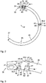
- the frame lock 11 comprises a lock body 13 with a housing 15 which is at least essentially C-shaped, with a middle section of the C-shape being widened in the shape of a cuboid and the two remaining sections having a first leg 17 and a second leg 19 of the lock body 13 form that extend out of corners of the cuboid shape.
- a non-visible locking device in the form of a locking cylinder and a bolt 21 coupled to the locking device (cf. Figures 6 and 7 ) recorded.
- the locking device can only be actuated regularly by means of a key 23 assigned to the locking device.
- the bolt 21 is coupled to the locking device in such a way that it can be moved between an unlocked position and a locked position by actuating the locking device using the key 23 .
- the frame lock 11 also has a rotary bracket 25, which extends along a circular path and is accommodated at least partially in the housing 15, namely in a rotary bracket mount that extends through the first leg 17 and into the cuboid central section of the lock body 13.
- the rotary bracket 25 is mounted relative to the lock body 13 in such a way that it can be adjusted between an open position and a closed position along its longitudinal extent, ie along the said circular path.
- the rotary bracket 25 has a constant cross-section in sections, which is circular in the example shown, but in principle also has a different shape, for example that of a regular polygon.
- the sections that have the constant cross-section together form a (far) predominant part, for example over 80%, in particular over 90%, of the longitudinal extension of the rotary bracket 25.
- the swivel bracket 25 protrudes with a free end 27 from the first leg 17 and extends to the second leg 19 and with the free end 27 into it, so that it connects the two legs 17, 19 and the lock body 13 and the rotary bracket 25 thereby form a closed ring.
- the rotating bracket 25 can reach through a wheel of the two-wheeler between its spokes and thus lock the wheel against rotation.
- the section of the rotating bracket 25 which is arranged outside of the housing 15 in the closed position forms a blocking section 29 of the rotating bracket 25 which has the said circular cross-section throughout.
- the blocking section 29 extends along said circular path over an angular range of approximately 60°.
- the swivel bracket 25 In the open position, on the other hand, the swivel bracket 25 is completely accommodated within the housing 15 or the free end 27 protrudes only slightly from the first leg 17 of the housing 15, so that a free space remains between the two legs 17, 19, within which the spokes of the wheel between the legs 17, 19 of the frame lock 11 can be moved through.
- the rotating bar 25 releases the wheel of the two-wheeler for rotation.
- the rotating bracket 25 can be moved manually by means of a handle 31 from the open position to the closed position and vice versa from the closed position back to the open position along the circular path, which corresponds to a rotation of the rotating bracket 25 about the center point M of the circular path.
- the handle 31 is coupled to the rotating bracket 25 and extends perpendicularly to the plane of said circular path, along which the rotating bracket 25 extends, through a slot 33 formed in the first leg 17 .
- the slot 33 in this case has an arcuate course, the circular arc shape of the slot 33 corresponding to the course of the circular path, in particular being coaxial to the circular path, ie having the same center point M.
- the 1 shows the frame lock 11 in a side view, perpendicular to the circular path along which the rotating bracket 25 of the frame lock 11 extends. In the 2 and 4 the viewing direction is just the opposite.
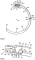
- the rotating bracket 25 of the frame lock 11 is shown separately. It can be seen that the free end 27 of the swivel bracket 25 has a conical chamfer.
- the swivel bracket 25 is fastened to the lock body 13 with its opposite end. In this respect, this end forms a coupled end 35 of the rotating bracket 25.
- the rotating bracket 25 is flattened on both sides perpendicular to the plane of the circular path and has, among other things for coupling to the lock body 13, a perpendicular to the plane of the circular path through the rotary bracket 25 extending hole 37 therethrough.
- the rotating bracket 25 has a blocking structure which comprises a plurality of webs 39 .
- Each of these webs 39 protrudes at least partially perpendicularly to the plane of the circular path from the rotating bracket 25 .
- the webs 39 each protrude beyond the above-mentioned circular cross-section, which sections of the rotating bracket 25 adjoining the respective web 39 have, in particular, along the circular path. The webs 39 thus extend outward beyond an outer contour of this cross section.
- the webs 39 are formed by cold forming.
- the rod material, from which the rotary bracket 25 is formed and which has the mentioned constant cross-section is clamped between a punch and a support either before bending into the arc of a circle (i.e.
- the respective web 39 has two mutually opposite parallel side faces 43 which are aligned radially outwards or inwards with respect to the center point M of the circular path and consequently extend essentially tangentially to the circular path.
- the side surfaces 43 extend both further out of rotary bracket 25 and further into rotary bracket 25 in comparison to the surface along the circular path adjoining web 39 of rotary bracket 25, so that part of the respective side surface 43, which extends into the rotating bracket 25, forms a side wall of the recess 41 adjoining the respective side surface 43.
- the two side surfaces 43 of a respective web 39 are connected by perpendicular to the side surfaces 43 and thus essentially radially to the center M of the circular path aligned edge sides, the two in opposite directions along the End faces 45 pointing in a circular path and an outer side 47 pointing perpendicularly to the plane of the circular path in the direction in which the web 39 protrudes from the rotating bracket 25 .
- the transitions between the end faces 45 and the outer side 47 are each rounded due to their formation by cold forming, but side surfaces 43 preferably have a comparatively small radius of curvature, in particular of at most 0.3 mm.
- the bolt 21 and the rotating bracket 25 are arranged relative to one another in such a way that, in its locking position, the bolt 21 is at least partially in the path of movement of the webs 39, which the webs 39 would pass through unhindered when the rotating bracket 25 was adjusted along the circular path.
- the bolt 21 when the bolt 21 is in its locking position, depending on the direction in which the rotating bracket 25 is adjusted, it engages behind one of the end faces 45 of the web 39 that is closest in this direction. If the rotating bracket 25 is adjusted in this direction, this end face 45 consequently strikes the bolt 21, so that the rotating bracket 25 is thereby blocked against further adjustment in this direction.
- this end face 45 forms a stop section 49 of the said locking structure of the rotating bracket 25, which is aligned at least essentially perpendicularly to the course of the circular path.
- the small radius of curvature mentioned contributes to the fact that the rotary bracket 25 with the respective stop section 49 cannot be pushed past the bolt 21 .
- the first web 39.1 is arranged along the longitudinal extent of the rotating bracket 25 in such a way that the bolt 21, when the rotating bracket 25 is in its closed position and the bolt 21 is moved into its locking position, engages in the movement path next to the first web 39.1.
- pointing end face 45 of the first web 39.1 then forms a stop section 49 arranged adjacent to the bolt 21, so that the rotating bracket 25 is blocked by the interaction of the bolt 21 with this stop section 49 against leaving the closed position in the opening direction becomes.
- the second web 39.2 is arranged along the longitudinal extent of the rotating bracket 25 in such a way that the bolt 21, when the rotating bracket 25 is in its open position and the bolt 21 is moved into its locking position, engages in the path of movement next to the second web 39.2.
- the along the circular path in a closing direction, in which the rotating bracket 25 can basically be adjusted from its open position to its closed position (in 2 and 4 the closing direction corresponds to the clockwise direction), pointing end face 45 of the second web 39.2 then forms a stop section 49 arranged adjacent to the bolt 21, so that the rotating bracket 25 is blocked by the interaction of the bolt 21 with this stop section 49 against leaving the open position in the closing direction becomes.
- the third web 39.3 is arranged along the longitudinal extension of the rotating bracket 25 in such a way that the bolt 21, when the rotating bracket 25 is in its closed position and the bolt 21 is moved into its locking position, engages in the movement path next to the third web 39.3.
- the end face 45 of the third web 39.2 pointing in the closing direction along the circular path then forms a stop section 49 arranged adjacent to the bolt 21, so that the rotating bracket 25 is blocked by the interaction of the bolt 21 with this stop section 49 in the closing direction via the to be adjusted in the closed position.
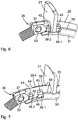
- the bolt 21 in its locking position thus engages between the first web 39.1 and the third web 39.3, in particular between the stop sections 49 of these two webs 39.1 and 39.3 (cf. also 6 ), so that the rotating bracket 25 is blocked in both adjustment directions along the circular path (opening direction and closing direction). Due to the additional locking also in the closing direction, the swivel bracket 25 is secured against being torn out of the lock body 13 in its closed position.
- the rotating bracket 25 also has a fourth web 39.4, which is in the 3 and 5 can be seen and has the same position as the first web 39.1 along the circular path, but in the opposite direction, ie in the 2 and 4 perpendicular to the image plane into this, protrudes from the rotary bracket 25. Furthermore, the rotary bracket 25 also has a fifth web 39.5, which has the same position as the second web 39.2 along the circular path, but protrudes from the rotary bracket 25 in the opposite direction. The fifth bridge 39.5 is in 1 through the slot 33 for the handle 31 can be seen.
- the fourth web 39.4 and the fifth web 39.5 are not only designed in a largely identical manner (apart from the opposite orientation) to the first web 39.1 or the second web 39.2, but also have the same function, namely in cooperation with the bolt 21 to block the rotating bracket 25 against leaving the closed position in the opening direction or the open position in the closing direction, so that the reliability of locking the rotating bracket 25 in a respective position is further improved by the fourth web 39.4 and the fifth web 39.5.
- the frame lock 11 also includes a strip 51 made of plastic, which is arranged on the rotating bracket 25 and in particular in the Figures 4 to 7 can be seen.
- the ledge 51 engages the hole 37 on the coupled end 35 of the pivot bracket 25 with a spigot 53 formed on the ledge 51 and extends from there over a large part of the longitudinal extent of the rotary bracket 25, in particular at least essentially up to the said blocking section 29.
- the strip 51 has at least in sections, namely in particular in the section between the first web 39.1 and the second web 39.2, an essentially C -shaped cross-section and thus covers the rotary bracket 25 with respect to the circular path both radially inward and in the two axial directions, ie perpendicular to the plane of the circular path.
- a part of the strip 51 rests against the surface of the rotary bracket 25 along an outer contour, which extends from the first web 39.1 with a course corresponding to the circular path to the second web 39.2.
- the height of the strip 51 i.e. the extension of the strip 51 radially to a center point of the cross section of the rotating bracket) corresponds to the extent by which the first web 39.1 and the second web 39.2 protrude from the rotating bracket 25, so that the strip 51 extends the area filled up between the two webs 39.1 and 39.2.
- a side surface 55 of the strip 51 which delimits the strip 51 in this area in the circumferential direction around the rotary bracket 25, is aligned with the two side surfaces 43 of the two webs 39.1 and 39.2, which point radially outwards with respect to the center point M of the circular path, so that the three side surfaces 49, 55 form a substantially continuous web.
- the bar 51 is (apart from the end at which it is coupled to the coupled end 35 of the rotary bracket 25 via the pin 53) formed symmetrically with respect to a plane parallel to the plane of the circular path. Therefore fills the bar 51 with a in the image plane 4 oriented in and therefore in 4
- the non-recognizable part also has the area between the fourth web 39.4 and the fifth web 39.5 and has a side surface 55 delimiting the strip 51 in the circumferential direction in this area, which with the two side surfaces 43 of the two webs 39.4 and 39.5 are aligned and thus form an essentially continuous path with them (cf. figure 5 ).
- the strip 51 Due to the extension of the strip 51 on the one hand from the first web 39.1 to the second web 39.2 and on the other hand from the fourth web 39.4 to the fifth web 39.5, the strip 51 forms a positive fit with these webs 39, at least with regard to the course of the circular path.
- the strip 51 can be fastened to the rotating bracket 25 in a snap-in manner, ie by an elastically reversible form fit, and can be caught between the webs 39 so that it cannot move relative to the rotating bracket 25 along the circular path. In this way, the material structure of the rotating bracket 25 is not impaired by the attachment of the strip 51 and the handle 31 provided thereon to the rotating bracket 25 .
- the strip 51 has a fastening attachment which is formed integrally with the strip 51 , namely is molded onto the strip 51 .
- This attachment approach extends perpendicular to the circular path and thus perpendicular to the image plane 4 into the image plane and is therefore not visible.
- FIGS. 6 and 7 illustrate the interaction of the bolt 21 with the rotary bracket 25, in particular with its webs 39, and with the strip 51.
- the bolt 21 can simultaneously interact with the webs 39.1 and 39.3 protruding from the rotary bracket 25 in a direction perpendicular to the plane of the circular path and the web 39.4 protruding from the rotary bracket 25 in the opposite direction is made possible by the fact that the bolt 21 is fork-shaped is formed and has a contour that the rotating bracket 25 according to its cross section, so in the example shown semicircular, engages. As a result, the bolt 21 has two arms, into which the contour ends on one side and on the other side and which can thus interact with one or more respective webs 39 on (axially with respect to the circular path) opposite sides of the rotary bracket 25 can engage behind a stop section 49 of the respective web 39 .
- the latch 21 can thereby slide along the circular path on both sides along the two continuous paths during the adjustment of the rotating bracket 25, which run through one side surface 55 of the bar 51 and the side surfaces 43 of the first web 39.1 and second web 39.2 or through the other side surface 55 the bar 51 and the side faces 43 of the fourth web 39.4 and the fifth web 39.5 are formed.
- the bolt 21 is held in its unlocked position during an adjustment from the closed position to the open position and during an adjustment from the open position to the closed position and therefore does not have to be adjusted into the unlocked position again before the respective position is reached, so that a respective the webs 39 can be guided past the bolt 21.
- the locking device is designed in such a way and is coupled to the bolt 21 in such a way that the key 23 can only be removed from the locking device when the bolt 21 is in its locking position, this also ensures that the key 23 is not in an intermediate position of the rotating bracket 25 between its open position and its closed position can be deducted.
- rotary bracket 25 with a stop section 49 which is formed by cold forming and/or on a web 39 protruding from rotary bracket 25, allows various advantageous functions to be implemented, with such a rotary bracket 25 can be produced easily and inexpensively, in particular also in an automated manner, is hardly affected in terms of its material structure and therefore has a particularly stable structure, so that it is suitable for securing a two-wheeler in a particularly reliable manner.
Landscapes
- Engineering & Computer Science (AREA)
- Mechanical Engineering (AREA)
- Lock And Its Accessories (AREA)
Applications Claiming Priority (1)
| Application Number | Priority Date | Filing Date | Title |
|---|---|---|---|
| DE102021114206.7A DE102021114206B4 (de) | 2021-06-01 | 2021-06-01 | Rahmenschloss |
Publications (3)
| Publication Number | Publication Date |
|---|---|
| EP4098528A1 true EP4098528A1 (fr) | 2022-12-07 |
| EP4098528B1 EP4098528B1 (fr) | 2025-04-16 |
| EP4098528C0 EP4098528C0 (fr) | 2025-04-16 |
Family
ID=81750572
Family Applications (1)
| Application Number | Title | Priority Date | Filing Date |
|---|---|---|---|
| EP22174559.9A Active EP4098528B1 (fr) | 2021-06-01 | 2022-05-20 | Serrure en châssis |
Country Status (4)
| Country | Link |
|---|---|
| EP (1) | EP4098528B1 (fr) |
| CN (1) | CN115432088A (fr) |
| DE (1) | DE102021114206B4 (fr) |
| TW (1) | TW202248519A (fr) |
Citations (1)
| Publication number | Priority date | Publication date | Assignee | Title |
|---|---|---|---|---|
| DE102018121248A1 (de) * | 2018-08-30 | 2020-03-05 | ABUS August Bremicker Söhne KG | Schloss |
Family Cites Families (2)
| Publication number | Priority date | Publication date | Assignee | Title |
|---|---|---|---|---|
| DE202009002004U1 (de) | 2009-03-30 | 2009-10-01 | Yang, Tzu-Ying, Xihu | Rahmenschloss |
| DE202014006369U1 (de) | 2014-07-04 | 2014-10-27 | Axa Stenman Nederland B.V. | Ringbügelschloss |
-
2021
- 2021-06-01 DE DE102021114206.7A patent/DE102021114206B4/de active Active
-
2022
- 2022-05-20 EP EP22174559.9A patent/EP4098528B1/fr active Active
- 2022-05-25 CN CN202210587500.4A patent/CN115432088A/zh active Pending
- 2022-05-26 TW TW111119696A patent/TW202248519A/zh unknown
Patent Citations (1)
| Publication number | Priority date | Publication date | Assignee | Title |
|---|---|---|---|---|
| DE102018121248A1 (de) * | 2018-08-30 | 2020-03-05 | ABUS August Bremicker Söhne KG | Schloss |
Also Published As
| Publication number | Publication date |
|---|---|
| DE102021114206A1 (de) | 2022-12-01 |
| CN115432088A (zh) | 2022-12-06 |
| DE102021114206B4 (de) | 2024-02-29 |
| EP4098528B1 (fr) | 2025-04-16 |
| TW202248519A (zh) | 2022-12-16 |
| EP4098528C0 (fr) | 2025-04-16 |
Similar Documents
| Publication | Publication Date | Title |
|---|---|---|
| DE3738924C2 (fr) | ||
| EP0636798B1 (fr) | Elément de fixation rotatif | |
| EP4098526B1 (fr) | Fermeture de cadre | |
| DE202008008090U1 (de) | Beschlag für einen Fahrzeugsitz | |
| EP0842081A1 (fr) | Dispositif de fixation frontale, a positionnement variable, d'un corps annulaire | |
| DE3734539A1 (de) | Doppelzylinderschloss | |
| EP1048804B1 (fr) | Système de verrouillage | |
| DE10225403B4 (de) | Ständerwerk | |
| DE102021114206B4 (de) | Rahmenschloss | |
| DE10146615B4 (de) | Laschenverbindung | |
| DE69718660T2 (de) | Schliessvorrichtung | |
| EP1163083B1 (fr) | Meuleuse d'angle | |
| DE3325123A1 (de) | Steckriegelschloss, insbesondere fuer zweiradfahrzeuge | |
| DE69404908T2 (de) | Scheibenwischer mit gelenkig verbundenen Elementen | |
| DE19911894A1 (de) | Kantengetriebe | |
| EP1101634B1 (fr) | Dispositif de remorquage et son procédé de fabrication | |
| EP3235984B1 (fr) | Ferrure de fenêtre, son procédé de fabrication et fenêtre correspondante | |
| DE3228613A1 (de) | Langbuegelschloss, insbesondere fuer zweiradfahrzeuge | |
| EP0683091A1 (fr) | Semure pour frein à disque | |
| DE19516848A1 (de) | Schließzylinder, insbesondere für Kraftfahrzeug-Türschlösser | |
| DE29704055U1 (de) | Aushängbares Türscharnier | |
| DE69613091T2 (de) | Ein System von Profilelementen und Einsatzsteuerelementen zur Verwendung in diesem System | |
| DE19634558B4 (de) | Vorrichtung aus zwei zueinander verschiebbaren Körpern, Verstellwerkzeug und Verfahren zur Herstellung einer Paarung aus einer solchen Vorrichtung und einem solchen Verstellwerkzeug | |
| DE102008053660B4 (de) | Nabe für einen Beschlag eines Fahrzeugsitzes, Beschlag für einen Fahrzeugsitz und Welle-Nabe-Anordnung für einen Beschlag eines Fahrzeugsitzes | |
| WO2000055459A1 (fr) | Mecanisme a aretes |
Legal Events
| Date | Code | Title | Description |
|---|---|---|---|
| PUAI | Public reference made under article 153(3) epc to a published international application that has entered the european phase |
Free format text: ORIGINAL CODE: 0009012 |
|
| STAA | Information on the status of an ep patent application or granted ep patent |
Free format text: STATUS: THE APPLICATION HAS BEEN PUBLISHED |
|
| AK | Designated contracting states |
Kind code of ref document: A1 Designated state(s): AL AT BE BG CH CY CZ DE DK EE ES FI FR GB GR HR HU IE IS IT LI LT LU LV MC MK MT NL NO PL PT RO RS SE SI SK SM TR |
|
| STAA | Information on the status of an ep patent application or granted ep patent |
Free format text: STATUS: REQUEST FOR EXAMINATION WAS MADE |
|
| 17P | Request for examination filed |
Effective date: 20230322 |
|
| RBV | Designated contracting states (corrected) |
Designated state(s): AL AT BE BG CH CY CZ DE DK EE ES FI FR GB GR HR HU IE IS IT LI LT LU LV MC MK MT NL NO PL PT RO RS SE SI SK SM TR |
|
| STAA | Information on the status of an ep patent application or granted ep patent |
Free format text: STATUS: EXAMINATION IS IN PROGRESS |
|
| 17Q | First examination report despatched |
Effective date: 20230808 |
|
| GRAP | Despatch of communication of intention to grant a patent |
Free format text: ORIGINAL CODE: EPIDOSNIGR1 |
|
| STAA | Information on the status of an ep patent application or granted ep patent |
Free format text: STATUS: GRANT OF PATENT IS INTENDED |
|
| INTG | Intention to grant announced |
Effective date: 20241114 |
|
| GRAS | Grant fee paid |
Free format text: ORIGINAL CODE: EPIDOSNIGR3 |
|
| GRAA | (expected) grant |
Free format text: ORIGINAL CODE: 0009210 |
|
| STAA | Information on the status of an ep patent application or granted ep patent |
Free format text: STATUS: THE PATENT HAS BEEN GRANTED |
|
| AK | Designated contracting states |
Kind code of ref document: B1 Designated state(s): AL AT BE BG CH CY CZ DE DK EE ES FI FR GB GR HR HU IE IS IT LI LT LU LV MC MK MT NL NO PL PT RO RS SE SI SK SM TR |
|
| REG | Reference to a national code |
Ref country code: GB Ref legal event code: FG4D Free format text: NOT ENGLISH |
|
| REG | Reference to a national code |
Ref country code: CH Ref legal event code: EP |
|
| REG | Reference to a national code |
Ref country code: IE Ref legal event code: FG4D Free format text: LANGUAGE OF EP DOCUMENT: GERMAN |
|
| U01 | Request for unitary effect filed |
Effective date: 20250416 |
|
| U07 | Unitary effect registered |
Designated state(s): AT BE BG DE DK EE FI FR IT LT LU LV MT NL PT RO SE SI Effective date: 20250424 |
|
| U20 | Renewal fee for the european patent with unitary effect paid |
Year of fee payment: 4 Effective date: 20250527 |
|
| PG25 | Lapsed in a contracting state [announced via postgrant information from national office to epo] |
Ref country code: ES Free format text: LAPSE BECAUSE OF FAILURE TO SUBMIT A TRANSLATION OF THE DESCRIPTION OR TO PAY THE FEE WITHIN THE PRESCRIBED TIME-LIMIT Effective date: 20250416 |
|
| PG25 | Lapsed in a contracting state [announced via postgrant information from national office to epo] |
Ref country code: NO Free format text: LAPSE BECAUSE OF FAILURE TO SUBMIT A TRANSLATION OF THE DESCRIPTION OR TO PAY THE FEE WITHIN THE PRESCRIBED TIME-LIMIT Effective date: 20250716 |
|
| PG25 | Lapsed in a contracting state [announced via postgrant information from national office to epo] |
Ref country code: PL Free format text: LAPSE BECAUSE OF FAILURE TO SUBMIT A TRANSLATION OF THE DESCRIPTION OR TO PAY THE FEE WITHIN THE PRESCRIBED TIME-LIMIT Effective date: 20250416 |
|
| PG25 | Lapsed in a contracting state [announced via postgrant information from national office to epo] |
Ref country code: HR Free format text: LAPSE BECAUSE OF FAILURE TO SUBMIT A TRANSLATION OF THE DESCRIPTION OR TO PAY THE FEE WITHIN THE PRESCRIBED TIME-LIMIT Effective date: 20250416 |
|
| PG25 | Lapsed in a contracting state [announced via postgrant information from national office to epo] |
Ref country code: RS Free format text: LAPSE BECAUSE OF FAILURE TO SUBMIT A TRANSLATION OF THE DESCRIPTION OR TO PAY THE FEE WITHIN THE PRESCRIBED TIME-LIMIT Effective date: 20250716 |
|
| PG25 | Lapsed in a contracting state [announced via postgrant information from national office to epo] |
Ref country code: IS Free format text: LAPSE BECAUSE OF FAILURE TO SUBMIT A TRANSLATION OF THE DESCRIPTION OR TO PAY THE FEE WITHIN THE PRESCRIBED TIME-LIMIT Effective date: 20250816 |