EP4098528B1 - Frame lock - Google Patents
Frame lock Download PDFInfo
- Publication number
- EP4098528B1 EP4098528B1 EP22174559.9A EP22174559A EP4098528B1 EP 4098528 B1 EP4098528 B1 EP 4098528B1 EP 22174559 A EP22174559 A EP 22174559A EP 4098528 B1 EP4098528 B1 EP 4098528B1
- Authority
- EP
- European Patent Office
- Prior art keywords
- web
- bracket
- circular path
- rotary
- rotary hoop
- Prior art date
- Legal status (The legal status is an assumption and is not a legal conclusion. Google has not performed a legal analysis and makes no representation as to the accuracy of the status listed.)
- Active
Links
Images

Classifications
-
- B—PERFORMING OPERATIONS; TRANSPORTING
- B62—LAND VEHICLES FOR TRAVELLING OTHERWISE THAN ON RAILS
- B62H—CYCLE STANDS; SUPPORTS OR HOLDERS FOR PARKING OR STORING CYCLES; APPLIANCES PREVENTING OR INDICATING UNAUTHORIZED USE OR THEFT OF CYCLES; LOCKS INTEGRAL WITH CYCLES; DEVICES FOR LEARNING TO RIDE CYCLES
- B62H5/00—Appliances preventing or indicating unauthorised use or theft of cycles; Locks integral with cycles
- B62H5/14—Appliances preventing or indicating unauthorised use or theft of cycles; Locks integral with cycles preventing wheel rotation
- B62H5/147—Appliances preventing or indicating unauthorised use or theft of cycles; Locks integral with cycles preventing wheel rotation by means of circular bolts
-
- B—PERFORMING OPERATIONS; TRANSPORTING
- B62—LAND VEHICLES FOR TRAVELLING OTHERWISE THAN ON RAILS
- B62H—CYCLE STANDS; SUPPORTS OR HOLDERS FOR PARKING OR STORING CYCLES; APPLIANCES PREVENTING OR INDICATING UNAUTHORIZED USE OR THEFT OF CYCLES; LOCKS INTEGRAL WITH CYCLES; DEVICES FOR LEARNING TO RIDE CYCLES
- B62H5/00—Appliances preventing or indicating unauthorised use or theft of cycles; Locks integral with cycles
- B62H5/14—Appliances preventing or indicating unauthorised use or theft of cycles; Locks integral with cycles preventing wheel rotation
- B62H5/142—Appliances preventing or indicating unauthorised use or theft of cycles; Locks integral with cycles preventing wheel rotation by means of pivoting, or pivoting and sliding bolts
Definitions
- the invention relates to a frame lock for a two-wheeler.
- Frame locks typically differ from mobile bicycle locks in that they are firmly and usually permanently connected to the frame of the bicycle, for example, screwed to the frame.
- the frame lock is arranged in such a way that a shackle of the frame lock can be selectively adjusted to a position in which it engages between the spokes of a wheel of the bicycle, thus preventing the bicycle from being ridden in this way.
- the shackle is expediently secured by a bolt of the frame lock, which, at least ideally, can only be adjusted via a locking cylinder or other locking device of the frame lock, for the operation of which the user must have a secret key, such as a key.
- Typical designs for the shackle include, on the one hand, a swivel shackle with a straight profile and, on the other hand, a rotating shackle with a circular arc.
- a generic frame lock with a rotating shackle is made, for example, of DE 10 2018 121 248 A1 known.
- a frame lock can comprise a lock body with a bolt and a rotating bracket which extends along a circular path and is adjustable relative to the lock body along the circular path between an open position in which it releases a wheel of the bicycle for rotation and a closed position in which it locks the wheel against rotation, wherein the rotating bracket has a locking structure with a stop section, wherein the bolt is adjustable between an unlocking position and a locking position and wherein, when the rotary bracket is in its closed position and the bolt is in its locking position, the bolt engages behind the stop section and thereby locks the rotary bracket against being adjusted into the open position.
- the stability of the shackle is a crucial factor for the reliability of the frame lock. To ensure that the frame lock cannot be forced open, the shackle must be particularly strong. At the same time, the aim is to manufacture the shackle as cost-effectively and as fully automated as possible.
- a pivoting shackle for a frame lock can, for example, be made from a bar stock, in particular a metal wire, which is bent into a circular arc.
- a recess can be machined into this bar stock, for example, by punching or milling.
- a side wall of this recess can form the stop section.
- machining has the disadvantage that the machined material is weakened as a result, since fibers running lengthwise through the bar stock are interrupted. In particular, this can result in distortion during subsequent hardening of the pivoting shackle, which can even lead to breakage during subsequent straightening.
- the frame lock according to the invention for a two-wheeler comprises a lock body with a bolt and a rotating bracket which extends along a circular path and is adjustable relative to the lock body along the circular path between an open position in which it releases a wheel of the two-wheeler for rotation and a closed position in which it locks the wheel against rotation.
- the rotating bracket is preferably formed from a rod material, in particular a metal wire, such as steel wire, wherein the rod material preferably has a constant cross-section.
- the diameter of the circular path can, for example, be in the range between 10 cm and 15 cm, for example approximately 13 cm.
- the rotating bracket can have a diameter on the order of a few millimeters to a few centimeters.
- the diameter of the cross-section can be, at least on average, approximately 8 or 9 mm.
- the rotating bracket Due to its extension along the circular path, the rotating bracket has a circular arc shape that extends over a certain partial region of the circularly closed circular path, for example over an angular range of at least 200° and/or at most 250°, preferably of at least 210° and/or at most 240°, in particular of approximately 225° or 230°.
- the rotary bracket is adjustable between the open and closed positions, the rotary bracket can be adjusted from the open position in a closing direction to the closed position and vice versa from the closed position in an opening direction opposite to the closing direction to the open position.
- this does not exclude the possibility of the rotary bracket being adjusted in other ways, in particular in the closing direction beyond the closed position. and/or in the opening direction beyond the open position.
- Adjusting the rotating bracket corresponds to rotating the rotating bracket around an axis of rotation that runs through the center of the circular path and is perpendicular to a plane in which the circular path lies.
- the rotating yoke In the closed position, the rotating yoke preferably extends out of the lock body, in particular out of the aforementioned housing of the lock body, and then at least with one free end back into the lock body, in particular into the housing, so that the lock body and the rotating yoke preferably form a closed ring in the closed position. In this way, the respective wheel can be locked against rotation particularly reliably.
- the rotating yoke In the open position, however, the rotating yoke extends out of the lock body, but not back into it, or is at least almost completely accommodated in the lock body, in particular in the housing.
- the stop section is preferably, but not necessarily, designed as a stop surface, i.e., flat.
- the stop section can also be formed by an edge or a contour of the locking structure.
- the locking structure can be designed in many different ways.
- One fundamentally conceivable, but not claimed, way is for the locking structure to comprise a notch or recess in the rotating bracket, wherein the notch or recess can extend, in particular, radially from the outside to the inside of the rotating bracket with respect to the center of the circular path.
- the stop section can be designed as a side wall of such a notch or recess.
- the locking structure can have a plurality of stop sections, each of which can be engaged behind by the latch to secure different positions of the rotary bracket against departure from the respective position in at least one adjustment direction.
- Several of the stop sections can serve to secure the same position, whether with respect to the same adjustment direction or opposite adjustment directions.
- the aforementioned engagement of the locking bar behind the stop section is to be understood as referring to the adjustment of the rotary bracket to be locked.
- the locking bar engages transversely to the circular path in a movement path of the locking bar that the locking bar would follow if the locking bar were in its unlocked position and the rotary bracket were adjusted along the circular path in the direction of adjustment to be locked.
- the bolt When the rotary bracket is in its closed position and the bolt is in its locking position, the bolt preferably rests against the stop section or at least has a small distance, for example of less than 1 mm, in particular of a few hundred micrometers, from the stop section. This advantageously prevents the pivoting bracket from leaving the closed position in the direction of the open position.
- the bolt can also be spaced a greater distance from the stop section, so that the pivoting bracket can be adjusted from the closed position by a distance corresponding to this distance, but is in any case prevented from reaching a position in which the pivoting bracket would no longer reliably lock the wheel against rotation.
- the locking structure comprises at least one web which protrudes from the rotating bracket, in particular transversely to the longitudinal extent of the rotating bracket, and which has the stop section.
- the entire web need not protrude from the pivot bracket; it is sufficient for the web to protrude partially from the pivot bracket.
- a portion of the web may also extend into the pivot bracket, particularly transversely to the longitudinal extent of the pivot bracket.
- the portion of the web protruding from the pivot bracket may, in particular, represent a convex structure relative to its surroundings.
- the rotating bracket may have further sections with the same cross-section.
- all sections located along the circular path between two webs projecting from the rotating bracket preferably all web-free sections of the rotating bracket (possibly with the exception of end sections at both ends of the longitudinal extension of the rotating bracket) have the same cross-section.
- the web has two mutually opposite parallel side surfaces which extend at least substantially along the circular path, wherein the stop section is formed by an end face of the web which connects the side surfaces and is oriented at least substantially perpendicular to the circular path.
- the two side surfaces are preferably oriented parallel to the direction in which the web protrudes from the pivot bracket.
- the webs can extend along the circular path.
- the side surfaces can therefore have a curved course corresponding to the circular path.
- relatively short webs in particular can also have a straight course tangential to the circular path.
- Such a web with two parallel side surfaces can be formed comparatively easily and cost-effectively by cold forming.
- an outer portion of the section can be pressed, for example between a punch and a support, from opposite directions such that the material of this portion is formed into a web that at least partially protrudes outwards perpendicular to these directions.
- the two side surfaces of the web are thus aligned perpendicular to the two opposite directions from which the portion is pressed.
- a transition between the end face forming the stop section and an outer side of the web which connects the two side surfaces and is oriented away from the rotating bracket, has a radius of curvature of at most 1 mm, preferably at most 0.5 mm, in particular at most 0.3 mm, and/or at most 1.5%, preferably at most 1%, in particular at most 0.5%, of the radius of the circular path.
- the outer side can be one of the edge sides of the web mentioned. Due to the orientation of the outer side pointing away from the rotating bracket, the end face forming the stop section and the outer side can in particular be aligned at least substantially perpendicular to one another.
- the side surfaces of the web extend relative to a section of the rotary bracket adjacent to the web along the circular path, preferably relative to sections of the rotary bracket adjacent to the web on both sides along the circular path, both further both out of the pivot bracket and further into the pivot bracket, particularly relative to a surface of the respective section that faces outward in the direction of the web's protrusion and runs along the circular path.
- the webs can not only protrude from the pivot bracket, but also at least partially protrude into it, thus being particularly securely anchored to the pivot bracket.
- a recess formed in the pivot bracket adjoins each of the two side surfaces of the web.
- the recesses can, in particular, each be formed as a concave structure in the pivot bracket.
- the recesses can adjoin the respective side surface perpendicularly to the latter.
- a part of the respective side surface namely, in particular, a part of the respective side surface extending into the pivot bracket as explained above, can form a wall of the respective recess.
- Both recesses preferably have a constant cross-section, in particular the same, with respect to a direction perpendicular to the side surfaces.
- the two recesses can also be regarded as a single recess with a constant cross-section, which is divided in two, in particular precisely halved, by the web.
- the recesses can, in addition to the webs, contribute to locking the rotary bracket.
- the bolt not only engages behind the stop surface of the web, but also engages in at least one of the two recesses, preferably in both, when the rotary bracket is in its closed position and the bolt is in its locking position.
- the bolt preferably engages in a respective recess in such a way that adjustment of the rotary bracket along the circular path in at least one direction is blocked.
- the web can protrude from the rotating bracket in a direction perpendicular to the plane of the circular path.
- the web then protrudes axially from the rotating bracket, i.e., parallel to the axis of rotation extending through the center of the circular path and oriented perpendicular to the plane of the circular path.
- the web is preferably oriented radially outward.
- the material from which the swivel bracket is formed can have main fibers that run in a central region of the swivel bracket with respect to a direction perpendicular to the circular path and are important for the stability of the swivel bracket.
- main fibers that run in a central region of the swivel bracket with respect to a direction perpendicular to the circular path and are important for the stability of the swivel bracket.
- the locking structure of the swivel bracket comprises at least a pair of two webs arranged at the same position along the circular path and protruding in opposite directions from the swivel bracket (as will be explained further below), which then preferably protrude axially opposite one another from the swivel bracket.
- the said web that projects from the pivoting bracket and whose stop section is engaged behind by the bolt when the pivoting bracket is in its closed position and the bolt is in its locking position can also be referred to as the first web, without this designation being intended as an indication of a specific minimum, maximum or total number or of a specific order of priority or spatial sequence. which may include several webs projecting from the rotating bracket.
- the locking structure comprises a plurality of webs protruding from the rotary bracket, each of which has a stop section and can also be designed in particular according to one of the ways described for the first web, wherein the latch, when the rotary bracket is in a specific position and the latch is in its locking position, engages behind the stop section of a respective one of the webs and thereby locks the rotary bracket against adjustment from the specific position, at least in one of the two opposite adjustment directions along the circular path.
- the latch engages behind the respective stop section, in particular with regard to the adjustment direction to be locked.
- the specific position can be the closed position for one or more of the bars.
- the closed position of the pivot bracket not only the stop section of the first bar can be engaged behind by the bolt in its locked position, but also the (respective) stop section of one or more of the several bars protruding from the pivot bracket. In this way, the closed position can be secured particularly reliably by means of several bars protruding from the pivot bracket.
- the specific position for one or more of the protruding webs of the pivot bracket can also be a position of the pivot bracket other than the closed position.
- the pivot bracket can not only be locked in its closed position against adjustment (in at least one direction along the circular path) by means of the bolt, but also in one or more other positions, especially in its open position.
- the locking structure can comprise a further web protruding from the rotary bracket, which has a stop section and can also be designed in particular according to one of the ways described for the first web, wherein the bolt, when the rotary bracket is in its open position and the bolt is in its locking position, engages behind the stop section of this further web (with respect to the adjustment direction to be blocked) and thereby blocks the rotary bracket from being adjusted from the open position.
- the rotary bracket is then locked, in particular, at least against reaching the closed position, but preferably already against leaving the open position in the direction of the closed position.
- This additional web may be one of the aforementioned several webs protruding from the pivot bracket.
- this additional web may also be referred to as a second web, without this designation being understood as an indication of a specific minimum, maximum, or total number, or of a specific ranking or spatial sequence of the possibly several webs protruding from the pivot bracket.
- the same locking mechanism that locks the swivel bar in the closed position can also be used to prevent it from being moved from the open position. This can be useful to ensure that the swivel bar cannot be accidentally moved in the closing direction, especially while riding the bicycle, and thus interfere with the wheel.
- the locking structure can comprise a further web protruding from the rotary bracket, which has a stop section and can also be designed in particular in one of the ways described for the first web, wherein the bolt, when the rotary bracket is in its closed position and the bolt is in its locking position, engages behind the stop section of this further web (with respect to the adjustment direction to be blocked) and thereby blocks the rotary bracket against adjustment from the closed position in the direction away from the open position, i.e. in the closing direction beyond the closed position.
- the rotary bracket can already be blocked against leaving the closed position in this direction.
- This additional web may be one of the aforementioned several webs protruding from the pivoting bracket.
- this additional web may also be referred to as a third web, without this designation being understood as an indication of a specific minimum, maximum, or total number, or of a specific ranking or spatial sequence of the possibly several webs protruding from the pivoting bracket.
- the presence of the third web does not require the presence of the aforementioned second web.
- the pivot shackle can be secured in its closed position not only against adjustment in the opening direction, but also against adjustment in the closing direction.
- Such an additional security feature can be useful to ensure that the pivot shackle cannot be forcibly torn out of the lock body in the closing direction.
- At least two of the Webs have the same position along the circular path and protrude from the rotary bracket in opposite directions, in particular diametrically opposite one another with respect to a center point of the cross section of the rotary bracket, wherein the latch is designed such that, when the rotary bracket is in the respective position to be locked and the latch is in its locking position, it engages behind both the stop section of one of the webs and the stop section of the other of the webs.
- their two stop sections can have the same position along the circular path.
- their stop sections lie in the same plane.
- the respective position to be locked may in particular be the above-mentioned specific position of the rotary bracket, in which the rotary bracket is locked against being adjusted from this position by engaging behind the stop section of a respective one of the two webs and which may in particular be the closed position or the open position of the rotary bracket.
- the bolt can in particular be fork-shaped with a semicircular contour enclosing the rotary bracket, which opens into two arms which, in the locking position of the bolt, engage behind the stop section of each of the two webs.
- the side surfaces can point in the direction corresponding to the movement of the bolt from its locking position to its unlocking position.
- the bolt can be pre-tensioned in the opposite direction, i.e., from the unlocking position to its locking position, and, after the bolt has been moved to release a locked position of the pivoting bracket into its unlocking position, can slide along the track formed by the side surfaces, pre-tensioned against the track, while the pivoting bracket is being adjusted. In this way, the bolt can be held in its unlocking position, or at least in a position that does not lock the pivoting bracket, by means of the bar during the movement of the pivoting bracket.
- the strip is attached to the swivel bracket in a form-fitting manner, in particular by snapping into place.
- the strip can form a form-fitting connection with at least one of the possibly several webs projecting from the swivel bracket.
- the strip can be caught between the two webs, between which it at least extends, in such a way that It must be clearly fixed relative to the rotating bracket along the circular path, i.e., it cannot be moved along the circular path relative to the rotating bracket (but only together with it).
- the bar is positively attached to the rotating bracket in any spatial direction.
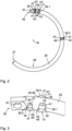
- the frame lock 11 comprises a lock body 13 with a housing 15 that is at least substantially C-shaped, wherein a central section of the C-shape is widened in a cuboid shape and the two remaining sections form a first leg 17 and a second leg 19 of the lock body 13, which extend from corners of the cuboid shape.
- a non-visible locking device in the form of a locking cylinder and a bolt 21 coupled to the locking device (cf. Figs. 6 and 7 ).
- the locking device can only be normally operated using a key 23 assigned to the locking device.
- the bolt 21 is coupled to the locking device in such a way that it can be adjusted between an unlocked position and a locked position by actuating the locking device using the key 23.
- the frame lock 11 further comprises a rotating shackle 25, which extends along a circular path and is at least partially received in the housing 15, namely in a rotating shackle receptacle that extends through the first leg 17 and into the cuboid-shaped central section of the lock body 13.
- the rotating shackle 25 is mounted relative to the lock body 13 such that it can be adjusted along its longitudinal extent, i.e., along the aforementioned circular path, between an open position and a closed position.
- the rotating shackle 25 has a constant cross-section in sections, which is circular in the example shown, but could in principle also have a different shape, for example, that of a regular polygon.
- the sections having the constant cross-section together form a (far) predominant part, for example, over 80%, in particular over 90%, of the longitudinal extent of the rotating shackle 25.
- the rotating bracket 25 protrudes with a free end 27 from the first leg 17 and extends to the second leg 19 and into it with the free end 27, so that it connects the two legs 17, 19 and the lock body 13 and the rotating bracket 25 thereby form a closed ring.
- the rotating bracket 25 can, with appropriate
- the frame lock 11 is mounted on the frame of a bicycle (not shown)
- it can engage a wheel of the bicycle between its spokes, thus locking the wheel against rotation.
- the section of the rotating bracket 25 that is arranged outside the housing 15 in the closed position forms a blocking section 29 of the rotating bracket 25, which has the aforementioned circular cross-section throughout.
- the blocking section 29 extends along the aforementioned circular path over an angular range of approximately 60°.
- the rotating bracket 25 In the open position, however, the rotating bracket 25 is completely housed within the housing 15 or protrudes only slightly with its free end 27 from the first leg 17 of the housing 15, so that a free space remains between the two legs 17, 19, within which the spokes of the wheel can be moved between the legs 17, 19 of the frame lock 11. Thus, in its open position, the rotating bracket 25 releases the wheel of the bicycle for rotation.
- the rotating bracket 25 can be moved manually by means of a handle 31 from the open position to the closed position and vice versa, from the closed position back to the open position along the circular path, which corresponds to a rotation of the rotating bracket 25 about the center point M of the circular path.
- the handle 31 is coupled to the rotating bracket 25 and extends perpendicular to the plane of the circular path along which the rotating bracket 25 extends, through a slot 33 formed in the first leg 17.
- the slot 33 has a circular arc-shaped profile, wherein the circular arc shape of the slot 33 corresponds to the profile of the circular path, in particular is coaxial to the circular path, i.e. has the same center point M.
- Fig. 1 shows the frame lock 11 in a side view, perpendicular to the circular path along which the rotating bracket 25 of the frame lock 11 extends.
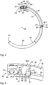
- Fig. 2 and 4 the direction of view is exactly the opposite.
- FIG. 2 The rotating shackle 25 of the frame lock 11 is shown separately. It can be seen that the free end 27 of the rotating shackle 25 has a conical chamfer. The opposite end of the rotating shackle 25 is attached to the lock body 13. This end thus forms a coupled end 35 of the rotating shackle 25. At the coupled end 35, the rotating shackle 25 is flattened on both sides perpendicular to the plane of the circular path and, among other things, for coupling to the lock body 13, has a hole 37 extending perpendicular to the plane of the circular path through the rotating shackle 25.
- the rotary bracket 25 has a locking structure comprising a plurality of webs 39.
- Each of these webs 39 protrudes at least partially from the rotary bracket 25 perpendicular to the plane of the circular path.
- the webs 39 each protrude beyond the aforementioned circular cross-section, which is particularly present in sections of the rotary bracket 25 adjacent to the respective web 39 along the circular path.
- the webs 39 thus extend outward beyond an outer contour of this cross-section.
- the webs 39 are formed by cold forming.
- the bar material from which the swivel bracket 25 is formed and which has the aforementioned constant cross-section is clamped between a punch and a support either before being bent into the circular arc shape (i.e., with a still straight profile) or with the arc already in the shape of a circle.
- a groove is formed in the direction in which the web 39 is to protrude.
- the bolt 21 and the rotary bracket 25 are arranged relative to one another in such a way that the bolt 21, in its locked position, is at least partially located in the path of movement of the webs 39, which the webs 39 would traverse unhindered when the rotary bracket 25 were adjusted along the circular path.
- the bolt 21 in its locked position, depending on the direction of adjustment of the rotary bracket 25, it engages behind one of the end faces 45 of the web 39 closest in this direction.
- this end face 45 consequently strikes the bolt 21, so that the rotary bracket 25 is thereby locked against further adjustment in this direction.
- the first web 39.1 is arranged along the longitudinal extent of the rotary bracket 25 in such a way that the bolt 21, when the rotary bracket 25 is in its closed position and the bolt 21 is adjusted to its locking position, engages in the movement path next to the first web 39.1.
- the movement along the circular path in an opening direction in which the rotary bracket 25 can basically be adjusted from its closed position to its open position (in Fig. 2 and 4 the opening direction corresponds to the counterclockwise direction), then forms a stop section 49 arranged adjacent to the bolt 21, so that the rotary bracket 25 is blocked by the interaction of the bolt 21 with this stop section 49 against leaving the closed position in the opening direction.
- the second web 39.2 is arranged along the longitudinal extent of the rotary bracket 25 in such a way that the bolt 21, when the rotary bracket 25 is in its open position and the bolt 21 is adjusted to its locking position, engages in the movement path next to the second web 39.2.
- the end face 45 of the second web 39.2 pointing in the opposite direction ie the closing direction corresponds to the clockwise direction
- the stop section 49 arranged adjacent to the bolt 21, so that the rotary bracket 25 is blocked by the interaction of the bolt 21 with this stop section 49 against leaving the open position in the closing direction.
- the third web 39.3 is arranged along the longitudinal extent of the pivot bracket 25 such that, when the pivot bracket 25 is in its closed position and the latch 21 is moved into its locking position, the latch 21 engages in the movement path of the third web 39.3 next to the third web 39.3.
- the end face 45 of the third web 39.2, which faces in the closing direction along the circular path, then forms a stop section 49 arranged adjacent to the latch 21, so that the pivot bracket 25 is blocked from being moved in the closing direction beyond the closed position by the interaction of the latch 21 with this stop section 49.
- the bolt 21 engages in its locking position between the first web 39.1 and the third web 39.3, in particular between the stop sections 49 of these two webs 39.1 and 39.3 (see also Fig. 6 ), so that the rotary bracket 25 is locked in both adjustment directions along the circular path (opening and closing direction). Due to the additional locking in the closing direction, the rotary bracket 25 is secured against being torn out of the lock body 13 in its closed position.
- the rotating bracket 25 has a fourth web 39.4, which is inserted into the Fig. 3 and 5 can be seen and has the same position along the circular path as the first web 39.1, but in the opposite direction, ie in the Fig. 2 and 4 perpendicular to the image plane into the image plane, protruding from the rotating bracket 25. Furthermore, the rotating bracket 25 has a fifth web 39.5, which has the same position along the circular path as the second web 39.2, but protrudes in the opposite direction from the rotating bracket 25. The fifth web 39.5 is in Fig. 1 can be seen through the slot 33 for the handle 31.
- the fourth web 39.4 and the fifth web 39.5 are not only designed in a largely identical manner (except for the opposite orientation) to the first web 39.1 and the second web 39.2, respectively, but also have the same function, namely, in cooperation with the bolt 21, to lock the rotary bracket 25 against leaving the closed position in the opening direction or the open position in the closing direction, so that the reliability of locking the rotary bracket 25 in a respective position is further improved by the fourth web 39.4 and the fifth web 39.5.
- the frame lock 11 further comprises a strip 51 made of plastic, which is arranged on the rotating bracket 25 and in particular in the Fig. 4 to 7 can be seen.
- the strip 51 engages with a pin 53 formed on the strip 51 into the hole 37 at the coupled end 35 of the rotary bracket 25 and extends from there over a large part of the longitudinal extent of the rotary bracket 25, in particular at least substantially up to the aforementioned blocking section 29.
- the strip 51 has, at least in sections, namely in particular in the section between the first web 39.1 and the second web 39.2, a substantially C-shaped cross-section and thus covers the rotary bracket 25. with respect to the circular path both radially inwards and in the two axial directions, i.e. directions perpendicular to the plane of the circular path.
- a portion of the strip 51 rests against the surface of the pivot bracket 25 along an outer contour that extends from the first web 39.1, following a circular path, to the second web 39.2.
- the height of the strip 51 i.e., the radial extension of the strip 51 to a center point of the cross-section of the pivot bracket) corresponds to the extent by which the first web 39.1 and the second web 39.2 protrude from the pivot bracket 25, so that the strip 51 fills the area between the two webs 39.1 and 39.2.
- a side surface 55 of the strip 51 which delimits the strip 51 in this area in the circumferential direction around the rotating bracket 25, is aligned with the two side surfaces 43 of the two webs 39.1 and 39.2, which point radially outwards with respect to the center point M of the circular path, so that the three side surfaces 49, 55 form a substantially continuous path.
- the strip 51 is (apart from the end where it is coupled to the coupled end 35 of the rotary bracket 25 via the pin 53) symmetrical with respect to a plane parallel to the plane of the circular path. Therefore, the strip 51 fills the image plane of the Fig. 4 and therefore in Fig. 4 not visible part also the area between the fourth web 39.4 and the fifth web 39.5 and has a side surface 55 which delimits the strip 51 in this area in the circumferential direction and which is aligned with the two side surfaces 43 of the two webs 39.4 and 39.5 which point radially outwards with respect to the center point M of the circular path and thereby forms an essentially continuous path with them (cf. Fig. 5 ).
- the strip 51 Due to the extension of the strip 51 on the one hand from the first web 39.1 to the second web 39.2 and on the other hand from the fourth web 39.4 to the fifth web 39.5, the strip 51 forms a positive connection with these webs 39.
- the strip 51 can be fastened to the rotating bracket 25 in a snap-in manner, i.e. by an elastically reversible positive connection, and can be trapped between the webs 39, so that it cannot move along the circular path relative to the rotating bracket 25. In this way, the material structure of the rotating bracket 25 is not impaired by the fastening of the strip 51 and the handle 31 provided thereon to the rotating bracket 25.
- the strip 51 has a fastening projection formed integrally with the strip 51, namely molded onto the strip 51.
- This fastening projection extends perpendicular to the circular path and thus perpendicular to the image plane of the Fig. 4 into the image plane and is therefore not visible.
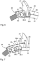
- Figs. 6 and 7 illustrate the interaction of the bolt 21 with the rotating bracket 25, in particular with its webs 39, and with the bar 51.
- FIG. 6 A state is shown in which the rotating bracket 25 is in its closed position and the bolt 21 is in its locking position.
- the bolt 21 engages behind both the stop section 49 of the first web 39.1 and the stop section 49 of the oppositely oriented fourth web 39.4 (cf. Fig. 7 ) with respect to an adjustment of the rotary bracket 25 in the opening direction, i.e., toward the open position, and therefore blocks such adjustment.
- the bolt 21 also engages behind the stop section 49 of the third web 39.3 (cf. Fig. 7 ) with regard to adjustment in the closing direction and thus also blocks such adjustment.
- the bolt 21 can simultaneously interact with the webs 39.1 and 39.3 projecting from the rotating bracket 25 in a direction perpendicular to the plane of the circular path and the web 39.4 projecting from the rotating bracket 25 in the opposite direction is made possible by the fact that the bolt 21 is fork-shaped and has a contour that surrounds the rotary bracket 25 according to its cross-section, i.e., semicircular in the example shown.
- the latch 21 has two arms, into which the contour opens on one side and the other, respectively, and which can thus interact with one or more respective webs 39 on opposite sides of the rotary bracket 25 (axially with respect to the circular path), in particular can engage behind a stop section 49 of the respective web 39.
- the latch 21 can slide on both sides along the two continuous paths formed by one side surface 55 of the strip 51 and the side surfaces 43 of the first web 39.1 and second web 39.2 or by the other side surface 55 of the strip 51 and the side surfaces 43 of the fourth web 39.4 and the fifth web 39.5.
- the bolt 21 is held in its unlocked position during an adjustment from the closed position to the open position as well as during an adjustment from the open position to the closed position and therefore does not need to be adjusted into the unlocked position again before reaching the respective position so that a respective one of the webs 39 can be guided past the bolt 21.
- the locking device is designed and coupled to the bolt 21 in such a way that the key 23 from the Since the locking device can only be removed when the bolt 21 is in its locking position, this also ensures that the key 23 cannot be removed in an intermediate position of the rotating bracket 25 between its open position and its closed position.
Landscapes
- Engineering & Computer Science (AREA)
- Mechanical Engineering (AREA)
- Lock And Its Accessories (AREA)
Description
Die Erfindung betrifft ein Rahmenschloss für ein Zweirad.The invention relates to a frame lock for a two-wheeler.
Von mobilen Zweiradschlössern unterscheiden sich Rahmenschlösser typischerweise dadurch, dass sie fest und in der Regel dauerhaft mit dem Rahmen des Zweirads verbunden, beispielsweise an dem Rahmen angeschraubt, sind. Das Rahmenschloss wird dabei derart angeordnet, dass ein Bügel des Rahmenschlosses wahlweise in eine Stellung verstellt werden kann, in der er zwischen die Speichen eines Rades des Zweirads eingreift, um ein Fahren mit dem Zweirad auf diese Weise zu verhindern. In dieser Stellung wird der Bügel zweckmäßigerweise durch einen Riegel des Rahmenschlosses gesichert, der sich zumindest idealerweise ausschließlich über einen Schließzylinder oder eine sonstige Schließeinrichtung des Rahmenschlosses verstellen lässt, zu deren Betätigung ein Nutzer über ein Schließgeheimnis, wie etwa einen Schlüssel, verfügen muss. Typische Bauformen für den Bügel sind einerseits eine Ausbildung als Schwenkbügel mit geradem Verlauf und andererseits eine Ausbildung als Drehbügel mit kreisbogenförmigem Verlauf. Ein gattungsgemässes Rahmenschloss mit einem Drehbügel ist beispielsweise aus
Insbesondere kann ein Rahmenschloss einen Schlosskörper mit einem Riegel sowie einen Drehbügel umfassen, der sich längs einer Kreisbahn erstreckt und relativ zu dem Schlosskörper entlang der Kreisbahn zwischen einer Offenstellung, in der er ein Rad des Zweirads für eine Drehung freigibt, und einer Geschlossenstellung, in der er das Rad gegen Drehung sperrt, verstellbar ist, wobei der Drehbügel eine Sperrstruktur mit einem Anschlagabschnitt aufweist, wobei der Riegel zwischen einer Entriegelungsstellung und einer Verriegelungsstellung verstellbar ist, und wobei der Riegel, wenn sich der Drehbügel in seiner Geschlossenstellung befindet und sich der Riegel in seiner Verriegelungsstellung befindet, den Anschlagabschnitt hintergreift und den Drehbügel dadurch gegen ein Verstellen in die Offenstellung sperrt.In particular, a frame lock can comprise a lock body with a bolt and a rotating bracket which extends along a circular path and is adjustable relative to the lock body along the circular path between an open position in which it releases a wheel of the bicycle for rotation and a closed position in which it locks the wheel against rotation, wherein the rotating bracket has a locking structure with a stop section, wherein the bolt is adjustable between an unlocking position and a locking position and wherein, when the rotary bracket is in its closed position and the bolt is in its locking position, the bolt engages behind the stop section and thereby locks the rotary bracket against being adjusted into the open position.
Für die Zuverlässigkeit des Rahmenschlosses ist die Stabilität des Drehbügels ein entscheidender Faktor. Damit das Rahmenschloss möglichst nicht aufgebrochen werden kann, muss der Drehbügel besonders fest sein. Zugleich wird angestrebt, den Drehbügel möglichst kostengünstig und möglichst weitgehend automatisiert herstellen zu können.The stability of the shackle is a crucial factor for the reliability of the frame lock. To ensure that the frame lock cannot be forced open, the shackle must be particularly strong. At the same time, the aim is to manufacture the shackle as cost-effectively and as fully automated as possible.
Ein Drehbügel für ein Rahmenschloss kann beispielsweise aus einem Stangenmaterial, insbesondere einem Metalldraht, hergestellt werden, das in eine Kreisbogenform gebogen wird. Um die genannte Sperrstruktur mit dem Anschlagabschnitt auszubilden, kann in dieses Stangenmaterial durch spanende Bearbeitung eine Aussparung eingebracht, zum Beispiel ausgestanzt oder ausgefräst, werden. Eine Seitenwand dieser Aussparung kann dabei den Anschlagabschnitt bilden. Die spanende Bearbeitung hat aber den Nachteil, dass das bearbeitete Material dadurch geschwächt wird, da Fasern, die das Stangenmaterial längs durchziehen, unterbrochen werden. Insbesondere kann infolgedessen bei einem anschließenden Härten des Drehbügels ein Verzug entstehen, der bei einem nachfolgenden Richten sogar zu einem Bruch führen kann.A pivoting shackle for a frame lock can, for example, be made from a bar stock, in particular a metal wire, which is bent into a circular arc. To form the aforementioned locking structure with the stop section, a recess can be machined into this bar stock, for example, by punching or milling. A side wall of this recess can form the stop section. However, machining has the disadvantage that the machined material is weakened as a result, since fibers running lengthwise through the bar stock are interrupted. In particular, this can result in distortion during subsequent hardening of the pivoting shackle, which can even lead to breakage during subsequent straightening.
Es ist eine Aufgabe der Erfindung, ein Rahmenschloss für ein Zweirad mit einem Drehbügel oder einen Drehbügel für ein solches Rahmenschloss bereitzustellen, der möglichst einfach, kostengünstig und automatisiert herstellbar ist, dabei eine besonders stabile Struktur aufweist und dazu geeignet ist, das Zweirad besonders zuverlässig zu sichern.It is an object of the invention to provide a frame lock for a two-wheeler with a rotating shackle or a rotating shackle for such a frame lock, which can be produced as simply, cost-effectively and automatically as possible, has a particularly stable structure and is suitable for securing the two-wheeler particularly reliably.
Die Aufgabe wird gelöst durch ein Rahmenschloss mit den Merkmalen des Anspruchs 1. Vorteilhafte Ausführungsformen ergeben sich aus den abhängigen Ansprüchen, der vorliegenden Beschreibung sowie den Figuren.The object is achieved by a frame lock having the features of claim 1. Advantageous embodiments emerge from the dependent claims, the present description and the figures.
Das erfindungsgemäße Rahmenschloss für ein Zweirad umfasst einen Schlosskörper mit einem Riegel sowie einen Drehbügel, der sich längs einer Kreisbahn erstreckt und relativ zu dem Schlosskörper entlang der Kreisbahn zwischen einer Offenstellung, in der er ein Rad des Zweirads für eine Drehung freigibt, und einer Geschlossenstellung, in der er das Rad gegen Drehung sperrt, verstellbar ist.The frame lock according to the invention for a two-wheeler comprises a lock body with a bolt and a rotating bracket which extends along a circular path and is adjustable relative to the lock body along the circular path between an open position in which it releases a wheel of the two-wheeler for rotation and a closed position in which it locks the wheel against rotation.
Der Drehbügel ist vorzugsweise aus einem Stangenmaterial gebildet, insbesondere einem Metalldraht, wie etwa Stahldraht, wobei das Stangenmaterial bevorzugt einen konstanten Querschnitt aufweist. Der Durchmesser der Kreisbahn kann z.B. im Bereich zwischen 10 cm und 15 cm liegen, beispielsweise etwa 13 cm betragen. Im Querschnitt kann der Drehbügel einen Durchmesser in der Größenordnung von einigen Millimetern bis wenigen Zentimetern aufweisen. Beispielsweise kann der Durchmesser des Querschnitts zumindest im Mittel etwa 8 oder 9 mm betragen. Durch die Erstreckung längs der Kreisbahn weist der Drehbügel eine Kreisbogenform auf, die sich über einen bestimmten Teilbereich der kreisförmig geschlossenen Kreisbahn erstreckt, beispielsweise über einen Winkelbereich von mindestens 200° und/oder höchstens 250°, vorzugsweise von mindestens 210° und/oder höchstens 240°, insbesondere von etwa 225° oder 230°.The rotating bracket is preferably formed from a rod material, in particular a metal wire, such as steel wire, wherein the rod material preferably has a constant cross-section. The diameter of the circular path can, for example, be in the range between 10 cm and 15 cm, for example approximately 13 cm. In cross-section, the rotating bracket can have a diameter on the order of a few millimeters to a few centimeters. For example, the diameter of the cross-section can be, at least on average, approximately 8 or 9 mm. Due to its extension along the circular path, the rotating bracket has a circular arc shape that extends over a certain partial region of the circularly closed circular path, for example over an angular range of at least 200° and/or at most 250°, preferably of at least 210° and/or at most 240°, in particular of approximately 225° or 230°.
Da der Drehbügel zwischen der Offenstellung und der Geschlossenstellung verstellbar ist, kann der Drehbügel aus der Offenstellung in eine Schließrichtung bis in die Geschlossenstellung und umgekehrt aus der Geschlossenstellung in eine zu der Schließrichtung entgegengesetzte Öffnungsrichtung bis in die Offenstellung verstellt werden. Dadurch wird jedoch nicht ausgeschlossen, dass der Drehbügel noch in anderer Weise, insbesondere in Schließrichtung über die Geschlossenstellung hinaus und/oder in Öffnungsrichtung über die Offenstellung hinaus, verstellbar kann.Since the rotary bracket is adjustable between the open and closed positions, the rotary bracket can be adjusted from the open position in a closing direction to the closed position and vice versa from the closed position in an opening direction opposite to the closing direction to the open position. However, this does not exclude the possibility of the rotary bracket being adjusted in other ways, in particular in the closing direction beyond the closed position. and/or in the opening direction beyond the open position.
Bei einem Verstellen des Drehbügels entlang der Kreisbahn wird der Drehbügel mit seiner gebogenen Längserstreckung entlang der Kreisbahn verschoben, so dass er die Kreisbahn nicht verlässt, sondern sich nur über einen - hinsichtlich seiner Lage, jedoch nicht hinsichtlich seiner Winkelausdehnung - veränderten Teilbereich der Kreisbahn erstreckt. Das Verstellen des Drehbügels entspricht dabei einem Drehen des Drehbügels um eine Drehachse, die durch den Mittelpunkt der Kreisbahn verläuft und zu einer Ebene, in der die Kreisbahn liegt, senkrecht ausgerichtet ist.When the rotating bracket is adjusted along the circular path, the curved longitudinal extension of the rotating bracket is moved along the circular path so that it does not leave the circular path, but only extends over a portion of the circular path that is changed in terms of its position, but not in terms of its angular extent. Adjusting the rotating bracket corresponds to rotating the rotating bracket around an axis of rotation that runs through the center of the circular path and is perpendicular to a plane in which the circular path lies.
Bei der Verstellbarkeit des Drehbügels entlang der Kreisbahn handelt es sich um eine grundsätzliche Verstellbarkeit, die sich insbesondere aus einer entsprechenden Lagerung des Drehbügels an dem Schlosskörper ergeben kann. Die Verstellbarkeit muss aber nicht permanent vorliegen, sondern kann durch den genannten Riegel blockiert sein, insbesondere um den Drehbügel mittels des Riegels in einer oder mehreren verschiedenen bestimmten Stellungen sichern zu können. Vorzugsweise ist der Drehbügel zumindest aus der Offenstellung bis in die Geschlossenstellung sowie aus der Geschlossenstellung bis in die Offenstellung verstellbar, wenn weder der Riegel noch irgendein Hindernis in der Bewegungsbahn (zum Beispiel eine Speiche des Rades des Zweirads) ein Verstellen blockieren.The adjustability of the rotating yoke along the circular path is a fundamental adjustability, which can result in particular from a corresponding mounting of the rotating yoke on the lock body. However, the adjustability does not have to be permanent, but can be blocked by the aforementioned bolt, in particular in order to be able to secure the rotating yoke in one or more different specific positions by means of the bolt. Preferably, the rotating yoke is adjustable at least from the open position to the closed position and from the closed position to the open position, provided that neither the bolt nor any obstacle in the path of movement (for example, a spoke of the bicycle wheel) prevents adjustment.
Die Kreisbahn kann teilweise durch den Schlosskörper des Rahmenschlosses verlaufen, so dass sich der Drehbügel teilweise in oder durch den Schlosskörper erstrecken kann und dabei innerhalb des Schlosskörpers mit dem Riegel zusammenwirken kann. Vorzugsweise ist der Riegel dabei vollständig innerhalb eines Gehäuses des Schlosskörpers angeordnet, um von außen möglichst unzugänglich zu sein. Ferner kann der Drehbügel teilweise in dem Gehäuse des Schlosskörpers aufgenommen sein. Der Drehbügel kann insbesondere an diesem Gehäuse gelagert sein.The circular path can extend partially through the lock body of the frame lock, so that the rotating shackle can extend partially into or through the lock body and can interact with the bolt within the lock body. Preferably, the bolt is arranged entirely within a housing of the lock body in order to be as inaccessible from the outside as possible. Furthermore, the rotating shackle can be partially enclosed in the housing of the lock body. The rotating bracket can be mounted on this housing in particular.
In der Geschlossenstellung erstreckt sich der Drehbügel vorzugsweise aus dem Schlosskörper, insbesondere aus dem genannten Gehäuse des Schlosskörpers, heraus und anschließend zumindest mit einem freien Ende wieder in den Schlosskörper, insbesondere in das Gehäuse, hinein, so dass der Schlosskörper und der Drehbügel in der Geschlossenstellung vorzugsweise einen geschlossenen Ring bilden. Auf diese Weise kann das jeweilige Rad besonders zuverlässig gegen Drehung gesperrt werden. In der Offenstellung erstreckt sich der Drehbügel dagegen aus dem Schlosskörper hinaus, jedoch nicht wieder in diesen hinein oder ist zumindest nahezu vollständig in dem Schlosskörper, insbesondere in dem Gehäuse, aufgenommen.In the closed position, the rotating yoke preferably extends out of the lock body, in particular out of the aforementioned housing of the lock body, and then at least with one free end back into the lock body, in particular into the housing, so that the lock body and the rotating yoke preferably form a closed ring in the closed position. In this way, the respective wheel can be locked against rotation particularly reliably. In the open position, however, the rotating yoke extends out of the lock body, but not back into it, or is at least almost completely accommodated in the lock body, in particular in the housing.
Selbstverständlich kann der Drehbügel in seiner Geschlossenstellung das Rad eines jeweiligen Zweirads nur dann gegen Drehung sperren, wenn das Rahmenschloss in geeigneter Weise an dem Zweirad montiert ist. Mit anderen Worten: Das Rahmenschloss ist dazu ausgebildet, derart an dem Zweirad angeordnet zu werden, dass der Drehbügel in seiner Geschlossenstellung ein Rad des Zweirads gegen Drehung sperrt (insbesondere indem er das Rad durchgreift) und in seiner Offenstellung das Rad für eine Drehung freigibt.Of course, the rotating bar can only lock the wheel of a respective bicycle against rotation in its closed position if the frame lock is suitably mounted on the bicycle. In other words, the frame lock is designed to be arranged on the bicycle such that the rotating bar, in its closed position, locks a wheel of the bicycle against rotation (in particular by engaging through the wheel) and, in its open position, allows the wheel to rotate.
Erfindungsgemäß weist der Drehbügel eine Sperrstruktur mit einem Anschlagabschnitt auf, wobei der Riegel zwischen einer Entriegelungsstellung und einer Verriegelungsstellung verstellbar ist, und wobei der Riegel, wenn sich der Drehbügel in seiner Geschlossenstellung befindet und sich der Riegel in seiner Verriegelungsstellung befindet, den Anschlagabschnitt hintergreift und den Drehbügel dadurch gegen ein Verstellen in die Offenstellung sperrt.According to the invention, the rotary bracket has a locking structure with a stop portion, wherein the latch is adjustable between an unlocking position and a locking position, and wherein the latch, when the rotary bracket is in its closed position and the latch is in its locking position, engages behind the stop portion and thereby locks the rotary bracket against adjustment into the open position.
Der Riegel kann insbesondere relativ zu dem genannten Gehäuse des Schlosskörpers zwischen der Entriegelungsstellung und der Verriegelungsstellung verstellbar sein. Bei dem Verstellen kann es sich beispielsweise um ein lineares Versetzen handeln. Vorzugsweise lässt sich der Riegel nur über eine an dem Schlosskörper, insbesondere in dem Schlosskörper, vorgesehene Schließeinrichtung, bevorzugt in Form eines Schließzylinders, verstellen, mit der er, z.B. über einen Mitnehmer, gekoppelt ist und die nur mittels eines ihr zugeordneten Schlüssels betätigbar ist.The bolt can be adjusted, in particular, relative to the aforementioned housing of the lock body between the unlocked position and the locked position. The adjustment can, for example, be a linear displacement. Preferably, the bolt can only be adjusted via a locking device provided on the lock body, in particular in the lock body, preferably in the form of a locking cylinder, to which it is coupled, e.g., via a driver, and which can only be actuated using a key assigned to it.
Auch bei der Verstellbarkeit des Riegels handelt es sich um eine grundsätzliche Verstellbarkeit, die nicht permanent vorliegen muss, sondern insbesondere von der jeweiligen Stellung des Drehbügels abhängen kann. Vorzugsweise ist der Riegel jedenfalls dann aus der Entriegelungsstellung bis in die Verriegelungsstellung und umgekehrt aus der Verriegelungsstellung bis in die Entriegelungsstellung verstellbar, wenn sich der Drehbügel in seiner Geschlossenstellung befindet. Außerdem kann der Riegel insbesondere auch dann aus der Entriegelungsstellung bis in die Verriegelungsstellung und umgekehrt aus der Verriegelungsstellung bis in die Entriegelungsstellung verstellbar sein, wenn sich der Drehbügel in seiner Offenstellung befindet.The adjustability of the bolt is also a fundamental adjustability that does not have to be permanent, but can depend, in particular, on the respective position of the rotating bracket. Preferably, the bolt is adjustable from the unlocked position to the locked position and vice versa, from the locked position to the unlocked position, when the rotating bracket is in its closed position. Furthermore, the bolt can also be adjusted from the unlocked position to the locked position and vice versa, from the locked position to the unlocked position, when the rotating bracket is in its open position.
Somit kann der Drehbügel in seiner Geschlossenstellung durch den Riegel gesichert werden, indem der Riegel in seine Verriegelungsstellung verstellt wird und dann den Anschlagabschnitt der Sperrstruktur des Drehbügels hintergreift. Die Sperrung gegen ein Verstellen des Drehbügels entlang der Kreisbahn ist besonders zuverlässig, wenn der Anschlagabschnitt zumindest im Wesentlichen senkrecht zu der zu sperrenden Bewegungsrichtung, also zum Verlauf der Kreisbahn, des Drehbügels ausgerichtet ist, was daher bevorzugt ist.Thus, the pivoting bracket can be secured in its closed position by the bolt, which is moved into its locked position and then engages behind the stop section of the locking structure of the pivoting bracket. The locking against movement of the pivoting bracket along the circular path is particularly reliable if the stop section is aligned at least substantially perpendicular to the direction of movement to be blocked, i.e., to the course of the circular path, of the pivoting bracket, which is therefore preferred.
Der Anschlagabschnitt ist vorzugsweise, jedoch nicht notwendigerweise, als Anschlagfläche, also flächig ausgebildet. Grundsätzlich kann der Anschlagabschnitt auch durch eine Kante oder eine Kontur der Sperrstruktur gebildet werden.The stop section is preferably, but not necessarily, designed as a stop surface, i.e., flat. In principle, the stop section can also be formed by an edge or a contour of the locking structure.
Die Sperrstruktur kann auf viele verschiedene Weisen ausgebildet sein. Eine grundsätzlich denkbare, jedoch nicht beanspruchte Weise besteht darin, dass die Sperrstruktur einen Einschnitt oder eine Aussparung in dem Drehbügel umfasst, wobei sich der Einschnitt oder die Aussparung bezüglich des Mittelpunkts der Kreisbahn insbesondere radial von außen nach innen in den Drehbügel hinein erstrecken kann. Der Anschlagabschnitt kann dabei als eine Seitenwand eines solchen Einschnitts oder einer solchen Aussparung ausgebildet sein.The locking structure can be designed in many different ways. One fundamentally conceivable, but not claimed, way is for the locking structure to comprise a notch or recess in the rotating bracket, wherein the notch or recess can extend, in particular, radially from the outside to the inside of the rotating bracket with respect to the center of the circular path. The stop section can be designed as a side wall of such a notch or recess.
Die Sperrstruktur kann mehrere Anschlagabschnitte aufweisen, die jeweils von dem Riegel hintergriffen werden können, um verschiedene Stellungen des Drehbügels gegen ein Verlassen der jeweiligen Stellung in zumindest eine Verstellrichtung zu sichern. Dabei können mehrere der Anschlagabschnitte dem Sichern derselben Stellung dienen, sei es bezüglich derselben Verstellrichtung oder zueinander entgegengesetzter Verstellrichtungen.The locking structure can have a plurality of stop sections, each of which can be engaged behind by the latch to secure different positions of the rotary bracket against departure from the respective position in at least one adjustment direction. Several of the stop sections can serve to secure the same position, whether with respect to the same adjustment direction or opposite adjustment directions.
Das genannte Hintergreifen des Anschlagabschnitts durch den Riegel ist auf das zu sperrende Verstellen des Drehbügels bezogen zu verstehen. Insbesondere greift der Riegel dabei quer zum Verlauf der Kreisbahn in eine Bewegungsbahn des Anschlagabschnitts ein, die der Anschlagabschnitt durchlaufen würde, wenn sich der Riegel in seiner Entriegelungsstellung befände und der Drehbügel in die zu sperrende Verstellrichtung entlang der Kreisbahn verstellt würde.The aforementioned engagement of the locking bar behind the stop section is to be understood as referring to the adjustment of the rotary bracket to be locked. In particular, the locking bar engages transversely to the circular path in a movement path of the locking bar that the locking bar would follow if the locking bar were in its unlocked position and the rotary bracket were adjusted along the circular path in the direction of adjustment to be locked.
Wenn sich der Drehbügel in seiner Geschlossenstellung befindet und sich der Riegel in seiner Verriegelungsstellung befindet, liegt der Riegel vorzugsweise an dem Anschlagabschnitt an oder weist zumindest einen nur geringen Abstand, beispielsweise von weniger als 1 mm, insbesondere von wenigen hundert Mikrometern, von dem Anschlagabschnitt auf. Dadurch wird der Drehbügel vorteilhafterweise dagegen gesperrt, die Geschlossenstellung überhaupt in Richtung der Offenstellung zu verlassen. Grundsätzlich kann der Riegel aber auch einen größeren Abstand von dem Anschlagabschnitt aufweisen, so dass der Drehbügel zwar um eine diesem Abstand entsprechende Strecke aus der Geschlossenstellung verstellt werden kann, aber jedenfalls dagegen gesperrt wird, eine Stellung zu erreichen, in welcher der Drehbügel das Rad nicht länger zuverlässig gegen eine Drehung sperren würde.When the rotary bracket is in its closed position and the bolt is in its locking position, the bolt preferably rests against the stop section or at least has a small distance, for example of less than 1 mm, in particular of a few hundred micrometers, from the stop section. This advantageously prevents the pivoting bracket from leaving the closed position in the direction of the open position. In principle, however, the bolt can also be spaced a greater distance from the stop section, so that the pivoting bracket can be adjusted from the closed position by a distance corresponding to this distance, but is in any case prevented from reaching a position in which the pivoting bracket would no longer reliably lock the wheel against rotation.
Bei dem Rahmenschloss ist ferner vorgesehen, dass die Sperrstruktur zumindest einen von dem Drehbügel, insbesondere quer zur Längserstreckung des Drehbügels, vorstehenden Steg umfasst, der den Anschlagabschnitt aufweist.In the frame lock, it is further provided that the locking structure comprises at least one web which protrudes from the rotating bracket, in particular transversely to the longitudinal extent of the rotating bracket, and which has the stop section.
Es muss dabei nicht der gesamte Steg von dem Drehbügel vorstehen, sondern es genügt, wenn der Steg teilweise von dem Drehbügel vorsteht. Ein Teil des Stegs kann sich auch, insbesondere quer zur Längserstreckung des Drehbügels, in den Drehbügel hinein erstrecken. Der von dem Drehbügel vorstehende Teil des Stegs kann insbesondere eine relativ zu seiner Umgebung konvexe Struktur darstellen.The entire web need not protrude from the pivot bracket; it is sufficient for the web to protrude partially from the pivot bracket. A portion of the web may also extend into the pivot bracket, particularly transversely to the longitudinal extent of the pivot bracket. The portion of the web protruding from the pivot bracket may, in particular, represent a convex structure relative to its surroundings.
Der Steg kann beispielsweise relativ zu dem Querschnitt eines angrenzenden Abschnitts des Drehbügels vorstehen, insbesondere relativ zu dem Querschnitt eines Stangenmaterials, aus dem der Drehbügel gebildet ist, bevor daran die Sperrstruktur oder zumindest der Steg ausgebildet wurde. Dass der Steg über einen Querschnitt vorsteht, meint dabei insbesondere, dass sich der Steg - entlang der Erstreckung des Drehbügels längs der Kreisbahn betrachtet - über eine Außenkontur des Querschnitts hinaus erstreckt.The web can, for example, protrude relative to the cross-section of an adjacent section of the pivot bracket, in particular relative to the cross-section of a bar material from which the pivot bracket is formed before the locking structure or at least the web is formed thereon. The fact that the web protrudes beyond a cross-section means, in particular, that the web—viewed along the extension of the pivot bracket along the circular path—extends beyond an outer contour of the cross-section.
Die Richtung, in die der Steg vorsteht, ist vorzugsweise senkrecht zur Längserstreckung des Drehbügels. Insbesondere kann die Richtung zumindest im Wesentlichen radial bezüglich des Mittelpunkts eines zur Längserstreckung des Drehbügels senkrechten Querschnitts des Drehbügels sein.The direction in which the web projects is preferably perpendicular to the longitudinal extent of the swivel bracket. In particular, the direction can be at least substantially radially with respect to the center of a cross-section of the rotating bracket perpendicular to the longitudinal extent of the rotating bracket.
Der Anschlagabschnitt kann beispielsweise durch eine Stirnseite des Stegs gebildet werden. Insbesondere kann dabei auch der Anschlagabschnitt ganz oder zumindest teilweise von dem Drehbügel vorstehen.The stop section can, for example, be formed by an end face of the web. In particular, the stop section can protrude entirely or at least partially from the pivot bracket.
Der Steg stellt somit einen Teil der Sperrstruktur dar, mit welcher der Riegel zusammenwirkt, um den Drehbügel gegen ein Verstellen aus einer jeweiligen Stellung zu sperren. Hierzu ist der Steg vorteilhafterweise an entsprechender Position an dem Drehbügel ausgebildet. Mit anderen Worten ist der Steg dazu ausgebildet (insbesondere derart angeordnet), dass der Riegel den Anschlagabschnitt des Stegs hintergreift, wenn sich der Drehbügel in seiner Geschlossenstellung befindet und sich der Riegel in seiner Verriegelungsstellung befindet.The web thus represents part of the locking structure with which the latch cooperates to lock the pivoting bracket against being moved from a particular position. For this purpose, the web is advantageously formed at a corresponding position on the pivoting bracket. In other words, the web is designed (in particular arranged) such that the latch engages behind the stop portion of the web when the pivoting bracket is in its closed position and the latch is in its locked position.
Der Steg, insbesondere die gesamte Sperrstruktur, ist vorzugsweise innerhalb eines Abschnitts der Längserstreckung des Drehbügels, d.h. der Erstreckung des Drehbügels längs der Kreisbahn, angeordnet, der sowohl in der Geschlossenstellung als auch in der Offenstellung des Drehbügels (sowie in jeder Stellung dazwischen) innerhalb des Schlosskörpers, insbesondere eines Gehäuses des Schlosskörpers, angeordnet und somit vorteilhafterweise von außen nicht zugänglich ist.The web, in particular the entire locking structure, is preferably arranged within a section of the longitudinal extension of the rotary bracket, i.e. the extension of the rotary bracket along the circular path, which is arranged both in the closed position and in the open position of the rotary bracket (and in any position in between) within the lock body, in particular a housing of the lock body, and is thus advantageously not accessible from the outside.
Gemäß einer bevorzugten Ausführungsform ist der Anschlagabschnitt, vorzugsweise der gesamte Steg, durch Kaltumformung ausgebildet. Insbesondere kann der Steg dadurch ausgebildet sein, dass mittels eines Stempels, der gegen ein Auflager bewegt wird, ein dazwischen angeordneter Abschnitt des Drehbügels gepresst wird, so dass dieser Abschnitt parallel zur Pressrichtung zusammengedrückt und quer dazu gestreckt wird. Der so verformte Abschnitt steht dadurch teilweise von dem übrigen Drehbügel vor. Das genannte Kaltumformen kann insofern nach Art eines Fließpressens, insbesondere eines Querfließpressens, oder zumindest in dazu ähnlicher Weise erfolgen. Vorzugsweise ist die gesamte Sperrstruktur durch eine nicht-spanende Bearbeitung des Drehbügels ausgebildet. Insbesondere kann der gesamte Drehbügel, gegebenenfalls mit Ausnahme von Endabschnitten an den beiden Enden der Längserstreckung des Drehbügels, ausschließlich in nicht-spanender Weise bearbeitet sein.According to a preferred embodiment, the stop section, preferably the entire web, is formed by cold forming. In particular, the web can be formed by pressing an intermediate section of the rotary bracket by means of a punch that is moved against a support, so that this section is compressed parallel to the pressing direction and stretched transversely thereto. The section thus deformed thereby partially protrudes from the remaining rotary bracket. The aforementioned cold forming can thus in the manner of extrusion, in particular transverse extrusion, or at least in a similar manner. Preferably, the entire locking structure is formed by non-machining the rotary bracket. In particular, the entire rotary bracket, possibly with the exception of end sections at the two ends of the rotary bracket's longitudinal extension, can be machined exclusively in a non-machining manner.
Beispielsweise kann durch Kaltumformung eine Ausnehmung in dem Drehbügel ausgebildet werden. Der Anschlagabschnitt kann dann durch eine Seitenwand der Ausnehmung gebildet werden, welche die Ausnehmung in eine Richtung entlang der Kreisbahn begrenzt.For example, a recess can be formed in the rotary bracket by cold forming. The stop section can then be formed by a side wall of the recess, which delimits the recess in a direction along the circular path.
Die Kaltumformung bietet gegenüber einer spanenden Bearbeitung des Drehbügels den Vorteil, dass die Materialstruktur des bearbeiteten Materials durch die Bearbeitung weniger stark beeinträchtigt wird. Insbesondere kann durch eine Kaltumformung vermieden werden, dass für die Stabilität der Materialstruktur wichtige Fasern, insbesondere entlang der Längserstreckung des Drehbügels verlaufende Hauptfasern der Materialstruktur, unterbrochen werden.Compared to machining the swivel bracket, cold forming offers the advantage that the material structure of the processed material is less affected by the machining process. In particular, cold forming can prevent the disruption of fibers that are important for the stability of the material structure, especially the main fibers of the material structure that run along the longitudinal extension of the swivel bracket.
Gemäß einer Ausführungsform des erfindungsgemäßen Rahmenschlosses bzw. Drehbügels, bei dem die Sperrstruktur zumindest einen von dem Drehbügel vorstehenden Steg umfasst, der den Anschlagabschnitt aufweist, kann der Drehbügel aus einem Stangenmaterial gebildet sein, das einen konstanten, insbesondere kreisrunden, Querschnitt aufweist, wobei der Steg über diesen Querschnitt, insbesondere über eine Außenkontur dieses Querschnitts, hinaus nach außen vorsteht. Der Steg steht dabei also insofern von dem Drehbügel vor, als er sich, insbesondere bezüglich eines Mittelpunkts des Querschnitts des Drehbügels, in eine bestimmte Richtung weiter nach außen erstreckt als (von einer Biegung in die Kreisbogenform abgesehen) unbearbeitete Abschnitte des Stangenmaterials, aus dem der Drehbügel gebildet ist.According to one embodiment of the frame lock or swivel bracket according to the invention, in which the locking structure comprises at least one web protruding from the swivel bracket and having the stop section, the swivel bracket can be formed from a bar material having a constant, in particular circular, cross-section, wherein the web protrudes outward beyond this cross-section, in particular beyond an outer contour of this cross-section. The web thus protrudes from the swivel bracket insofar as it extends further outward in a certain direction, in particular with respect to a center point of the cross-section of the swivel bracket, than (apart from a bend into the circular arc shape) unmachined sections of the bar material from which the swivel bracket is formed.
Der Drehbügel kann einen Blockierabschnitt mit konstantem, insbesondere kreisrundem, Querschnitt umfassen, der sich entlang eines Teils der Längserstreckung des Drehbügels erstreckt und dazu ausgebildet ist, in der Geschlossenstellung des Drehbügels in das Rad, nämlich insbesondere zwischen die Speichen des Rades, einzugreifen und es dadurch gegen Drehung zu sperren. Hierzu ist der Blockierabschnitt in der Geschlossenstellung des Drehbügels vorzugsweise vollständig außerhalb eines Gehäuses des Schlosskörpers des Rahmenschlosses angeordnet. Der Steg kann dabei insofern von dem Drehbügel vorstehen, als er über den Querschnitt des Blockierabschnitts, insbesondere über eine Außenkontur dieses Querschnitts, hinaus nach außen vorsteht. Da der Steg außerhalb des Blockierabschnitts ausgebildet ist, muss hierzu der konstante Querschnitt des Blockierabschnitts gedanklich entlang der Kreisbahn bis zum Steg fortgesetzt werden.The pivot bracket can comprise a blocking section with a constant, in particular circular, cross-section, which extends along part of the longitudinal extent of the pivot bracket and is designed to engage with the wheel, namely in particular between the spokes of the wheel, in the closed position of the pivot bracket, and thereby lock it against rotation. For this purpose, the blocking section is preferably arranged completely outside a housing of the lock body of the frame lock in the closed position of the pivot bracket. The web can protrude from the pivot bracket insofar as it protrudes outwards beyond the cross-section of the blocking section, in particular beyond an outer contour of this cross-section. Since the web is formed outside the blocking section, the constant cross-section of the blocking section must be conceptually continued along the circular path up to the web.
Gemäß einer vorteilhaften Ausführungsform umfasst der Drehbügel bezüglich seiner Erstreckung längs der Kreisbahn zumindest zwei auf entgegengesetzten Seiten des Stegs liegende Abschnitte ohne Steg, die den gleichen konstanten, insbesondere kreisrunden, Querschnitt aufweisen, wobei der Steg über diesen Querschnitt, insbesondere über eine Außenkontur dieses Querschnitts, hinaus nach außen vorsteht. Der Steg ist also zwischen zwei stegfreien Abschnitten mit identischem Querschnitt angeordnet und der Steg steht insofern von dem Drehbügel vor, als er sich, insbesondere bezüglich eines Mittelpunkts des Querschnitts des Drehbügels, in eine bestimmte Richtung weiter nach außen erstreckt als diese beiden stegfreien Abschnitte.According to an advantageous embodiment, the pivot bracket, with respect to its extension along the circular path, comprises at least two sections without a web located on opposite sides of the web, which have the same constant, in particular circular, cross-section, wherein the web protrudes outward beyond this cross-section, in particular beyond an outer contour of this cross-section. The web is thus arranged between two web-free sections with identical cross-sections, and the web protrudes from the pivot bracket in that it extends further outward in a specific direction than these two web-free sections, in particular with respect to a center point of the cross-section of the pivot bracket.
Dabei kann der Drehbügel noch weitere Abschnitte mit demselben Querschnitt aufweisen. Insbesondere können alle Abschnitte, die entlang der Kreisbahn zwischen zwei von dem Drehbügel vorstehenden Stegen liegen, vorzugsweise alle stegfreien Abschnitte des Drehbügels (gegebenenfalls mit Ausnahme von Endabschnitten an den beiden Enden der Längserstreckung des Drehbügels) den gleichen Querschnitt aufweisen.The rotating bracket may have further sections with the same cross-section. In particular, all sections located along the circular path between two webs projecting from the rotating bracket, preferably all web-free sections of the rotating bracket (possibly with the exception of end sections at both ends of the longitudinal extension of the rotating bracket) have the same cross-section.
Wenn von einem Querschnitt des Drehbügels die Rede ist, so ist jeweils, sofern nicht anders angegeben, ein zur Längserstreckung des Drehbügels senkrechter Querschnitt gemeint, dessen Schnittebene aufgrund des kreisbogenförmigen Verlaufs der Längserstreckung zumindest im Wesentlichen radial zum Mittelpunkt der Kreisbahn ausgerichtet ist.When reference is made to a cross-section of the rotating bracket, this means, unless otherwise stated, a cross-section perpendicular to the longitudinal extent of the rotating bracket, the cutting plane of which is aligned at least substantially radially to the center of the circular path due to the circular arc-shaped course of the longitudinal extent.
Gemäß einer vorteilhaften Ausführungsform weist der Steg zwei zueinander entgegengesetzte parallele Seitenflächen auf, die sich zumindest im Wesentlichen längs der Kreisbahn erstrecken, wobei der Anschlagabschnitt durch eine Stirnseite des Stegs gebildet wird, welche die Seitenflächen verbindet und zumindest im Wesentlichen senkrecht zur Kreisbahn ausgerichtet ist. Die beiden Seitenflächen sind dabei vorzugsweise zu derjenigen Richtung parallel ausgerichtet, in die der Steg von dem Drehbügel vorsteht. Dabei können sich die Stege längs der Kreisbahn erstrecken. Je nachdem, in welche Richtung der Steg von dem Drehbügel vorsteht, können die Seitenflächen daher einen entsprechend der Kreisbahn gebogenen Verlauf aufweisen. Insbesondere eher kurze Stege können aber auch einen zur Kreisbahn tangentialen, geraden Verlauf aufweisen.According to an advantageous embodiment, the web has two mutually opposite parallel side surfaces which extend at least substantially along the circular path, wherein the stop section is formed by an end face of the web which connects the side surfaces and is oriented at least substantially perpendicular to the circular path. The two side surfaces are preferably oriented parallel to the direction in which the web protrudes from the pivot bracket. The webs can extend along the circular path. Depending on the direction in which the web protrudes from the pivot bracket, the side surfaces can therefore have a curved course corresponding to the circular path. However, relatively short webs in particular can also have a straight course tangential to the circular path.
Quer zum Verlauf der Kreisbahn sowie zur Richtung des Vorstehens können die Seitenflächen, jedenfalls soweit sie von dem Drehbügel vorstehen, durch jeweilige Ränder oder Randseiten des Stegs miteinander verbunden sein. Die Randseiten können dabei auch die genannte Stirnseite umfassen, durch die der Anschlagabschnitt gebildet wird. Vorzugsweise sind die Randseiten zumindest im Wesentlichen senkrecht zu den Seitenflächen ausgerichtet. Das gilt insbesondere auch für die Stirnseite, durch die der Anschlagabschnitt gebildet wird. Von einer zur Kreisbahn senkrechten Ausrichtung weicht die Ausrichtung des Anschlagabschnitts vorzugsweise um höchstens 10° ab.Transversely to the course of the circular path and to the direction of protrusion, the side surfaces, at least to the extent that they protrude from the pivoting bracket, can be connected to one another by respective edges or edge sides of the web. The edge sides can also include the aforementioned end face, which forms the stop section. Preferably, the edge sides are aligned at least substantially perpendicular to the side surfaces. This also applies in particular to the end face, which forms the stop section. The alignment of the stop section preferably deviates from an alignment perpendicular to the circular path by a maximum of 10°.
Ein derartiger Steg mit zwei parallelen Seitenflächen lässt sich vergleichsweise einfach und kostengünstig durch Kaltumformung ausbilden. Insbesondere kann in einem Abschnitt der Längserstreckung des Drehbügels (bzw. des Materials, aus dem der Drehbügel geformt wird), dessen (des Abschnitts) Länge der Länge des auszubildenden Stegs entspricht, ein äußerer Teilbereich des Abschnitts beispielsweise zwischen einem Stempel und einem Auflager aus entgegengesetzten Richtungen so gepresst werden, dass das Material dieses Teilbereichs zu einem senkrecht zu diesen Richtungen zumindest teilweise nach außen vorstehenden Steg umgeformt wird. Die beiden Seitenflächen des Stegs sind dadurch senkrecht zu den beiden entgegengesetzten Richtungen ausgerichtet, aus denen der Teilbereich gepresst wird.Such a web with two parallel side surfaces can be formed comparatively easily and cost-effectively by cold forming. In particular, in a section of the longitudinal extension of the swivel bracket (or of the material from which the swivel bracket is formed), the length of which corresponds to the length of the web to be formed, an outer portion of the section can be pressed, for example between a punch and a support, from opposite directions such that the material of this portion is formed into a web that at least partially protrudes outwards perpendicular to these directions. The two side surfaces of the web are thus aligned perpendicular to the two opposite directions from which the portion is pressed.
Wenn der Drehbügel einen Steg mit den genannten zwei Seitenflächen aufweist, kann gemäß einer vorteilhaften Ausführungsform vorgesehen sein, dass ein Übergang zwischen der Stirnseite, durch die der Anschlagabschnitt gebildet wird, und einer Außenseite des Stegs, welche die beiden Seitenflächen verbindet und von dem Drehbügel weg weisend ausgerichtet ist, einen Krümmungsradius von höchstens 1 mm, vorzugsweise höchstens 0,5 mm, insbesondere höchstens 0,3 mm, und/oder höchstens 1,5 %, vorzugsweise höchstens 1 %, insbesondere höchstens 0,5 %, des Radius der Kreisbahn aufweist. Bei der Außenseite kann es sich um eine der genannten Randseiten des Stegs handeln. Aufgrund der von dem Drehbügel wegweisenden Ausrichtung der Außenseite können die den Anschlagabschnitt bildende Stirnseite und die Außenseite insbesondere zumindest im Wesentlichen senkrecht zueinander ausgerichtet sein.If the rotating bracket has a web with the two side surfaces mentioned, it can be provided according to an advantageous embodiment that a transition between the end face forming the stop section and an outer side of the web, which connects the two side surfaces and is oriented away from the rotating bracket, has a radius of curvature of at most 1 mm, preferably at most 0.5 mm, in particular at most 0.3 mm, and/or at most 1.5%, preferably at most 1%, in particular at most 0.5%, of the radius of the circular path. The outer side can be one of the edge sides of the web mentioned. Due to the orientation of the outer side pointing away from the rotating bracket, the end face forming the stop section and the outer side can in particular be aligned at least substantially perpendicular to one another.
Gemäß einer weiteren vorteilhaften Ausführungsform erstrecken sich die Seitenflächen des Stegs relativ zu einem entlang der Kreisbahn an den Steg angrenzenden Abschnitt des Drehbügels, vorzugsweise relativ zu beidseitig entlang der Kreisbahn an den Steg angrenzenden Abschnitten des Drehbügels, sowohl weiter aus dem Drehbügel heraus als auch weiter in den Drehbügel hinein, insbesondere relativ zu einer in die Richtung des Vorstehens des Steges nach außen weisenden, entlang der Kreisbahn verlaufenden Oberfläche des jeweiligen Abschnitts. Auf diese Weise können die Stege nicht nur von dem Drehbügel vorstehen, sondern zumindest teilweise auch in diesen hineinragen und somit besonders stabil am Drehbügel verankert sein.According to a further advantageous embodiment, the side surfaces of the web extend relative to a section of the rotary bracket adjacent to the web along the circular path, preferably relative to sections of the rotary bracket adjacent to the web on both sides along the circular path, both further both out of the pivot bracket and further into the pivot bracket, particularly relative to a surface of the respective section that faces outward in the direction of the web's protrusion and runs along the circular path. In this way, the webs can not only protrude from the pivot bracket, but also at least partially protrude into it, thus being particularly securely anchored to the pivot bracket.
Gemäß einer weiteren vorteilhaften Ausführungsform grenzt an beide Seitenflächen des Stegs jeweils eine in dem Drehbügel ausgebildete Ausnehmung an. Die Ausnehmungen können insbesondere jeweils als eine konkave Struktur in dem Drehbügel ausgebildet sein. Ferner können die Ausnehmungen senkrecht zur jeweiligen Seitenfläche an diese angrenzen. Dabei kann ein Teil der jeweiligen Seitenfläche, nämlich insbesondere ein sich wie vorstehend erläutert in den Drehbügel hineinerstreckender Teil der jeweiligen Seitenfläche, eine Wand der jeweiligen Ausnehmung bilden.According to a further advantageous embodiment, a recess formed in the pivot bracket adjoins each of the two side surfaces of the web. The recesses can, in particular, each be formed as a concave structure in the pivot bracket. Furthermore, the recesses can adjoin the respective side surface perpendicularly to the latter. In this case, a part of the respective side surface, namely, in particular, a part of the respective side surface extending into the pivot bracket as explained above, can form a wall of the respective recess.
Beide Ausnehmungen weisen bezüglich einer zu den Seitenflächen senkrechten Richtung vorzugsweise einen, insbesondere denselben, konstanten Querschnitt auf. Die beiden Ausnehmungen können auch als eine einzelne Ausnehmung mit konstantem Querschnitt betrachtet werden, die durch den Steg zweigeteilt, insbesondere gerade halbiert, wird. Die Ausnehmungen können ergänzend zu den Stegen zu einem Verriegeln des Drehbügels beitragen. Dazu kann vorgesehen sein, dass der Riegel nicht nur die Anschlagfläche des Stegs hintergreift, sondern auch in zumindest eine der beiden Ausnehmungen, vorzugsweise in beide, eingreift, wenn sich der Drehbügel in seiner Geschlossenstellung befindet und sich der Riegel in seiner Verriegelungsstellung befindet. Der Riegel greift dabei vorzugsweise derart in eine jeweilige Ausnehmung ein, dass dadurch ein Verstellen des Drehbügels entlang der Kreisbahn in zumindest eine Richtung gesperrt wird.Both recesses preferably have a constant cross-section, in particular the same, with respect to a direction perpendicular to the side surfaces. The two recesses can also be regarded as a single recess with a constant cross-section, which is divided in two, in particular precisely halved, by the web. The recesses can, in addition to the webs, contribute to locking the rotary bracket. For this purpose, it can be provided that the bolt not only engages behind the stop surface of the web, but also engages in at least one of the two recesses, preferably in both, when the rotary bracket is in its closed position and the bolt is in its locking position. The bolt preferably engages in a respective recess in such a way that adjustment of the rotary bracket along the circular path in at least one direction is blocked.
Gemäß einer weiteren vorteilhaften Ausführungsform kann der Steg in eine zur Ebene der Kreisbahn senkrechte Richtung von dem Drehbügel vorstehen. Der Steg steht dann also axial, d. h. parallel zur durch den Mittelpunkt der Kreisbahn verlaufenden und senkrecht zur Ebene der Kreisbahn ausgerichteten Drehachse, von dem Drehbügel vor. Bezüglich eines Mittelpunkts des Querschnitts des Drehbügels ist der Steg dagegen (wie bereits erwähnt) vorzugsweise radial nach außen vorstehend ausgerichtet.According to a further advantageous embodiment, the web can protrude from the rotating bracket in a direction perpendicular to the plane of the circular path. The web then protrudes axially from the rotating bracket, i.e., parallel to the axis of rotation extending through the center of the circular path and oriented perpendicular to the plane of the circular path. With respect to a center of the cross-section of the rotating bracket, however, the web (as already mentioned) is preferably oriented radially outward.
Das Material, aus dem der Drehbügel gebildet ist, kann Hauptfasern aufweisen, die in einem bezüglich einer zur Kreisbahn senkrechten Richtung mittleren Bereich des Drehbügels verlaufen und für die Stabilität des Drehbügels wichtig sind. Dadurch dass der Steg bezüglich der Kreisbahn in axiale Richtung vorstehend ausgebildet wird, kann vermieden werden, dass diese Hauptfasern durch die Ausbildung des Stegs beeinträchtigt, insbesondere unterbrochen, werden. Die Stabilität des Drehbügels bleibt somit trotz der Bearbeitung des Drehbügels zur Ausbildung des Steges im Wesentlichen vollständig erhalten. Eine solche axiale Ausrichtung des Stegs ist insbesondere zweckmäßig, wenn die Sperrstruktur des Drehbügel zumindest ein Paar zweier an derselben Position entlang der Kreisbahn angeordneter und in entgegengesetzte Richtungen von dem Drehbügel vorstehender Stege umfasst (wie weiter unten noch erläutert wird), die dann vorzugsweise axial entgegengesetzt zueinander von dem Drehbügel vorstehen.The material from which the swivel bracket is formed can have main fibers that run in a central region of the swivel bracket with respect to a direction perpendicular to the circular path and are important for the stability of the swivel bracket. By designing the web to protrude in the axial direction with respect to the circular path, it can be avoided that these main fibers are impaired, in particular interrupted, by the formation of the web. The stability of the swivel bracket is thus essentially fully retained despite the machining of the swivel bracket to form the web. Such an axial orientation of the web is particularly expedient if the locking structure of the swivel bracket comprises at least a pair of two webs arranged at the same position along the circular path and protruding in opposite directions from the swivel bracket (as will be explained further below), which then preferably protrude axially opposite one another from the swivel bracket.
Zur begrifflichen Unterscheidung gegebenenfalls vorgesehener weitere von dem Drehbügel vorstehender Stege kann der genannte eine von dem Drehbügel vorstehende Steg, dessen Anschlagabschnitt von dem Riegel hintergriffen wird, wenn sich der Drehbügel in seiner Geschlossenstellung befindet und sich der Riegel in seiner Verriegelungsstellung befindet, auch als erster Steg bezeichnet werden, ohne dass diese Bezeichnung als Hinweis auf eine bestimmte Mindest-, Höchst- oder Gesamtanzahl oder auf eine bestimmte Rangfolge oder räumliche Abfolge der gegebenenfalls mehreren von dem Drehbügel vorstehenden Stege zu verstehen ist.In order to conceptually distinguish between any further webs that may be provided and projecting from the pivoting bracket, the said web that projects from the pivoting bracket and whose stop section is engaged behind by the bolt when the pivoting bracket is in its closed position and the bolt is in its locking position can also be referred to as the first web, without this designation being intended as an indication of a specific minimum, maximum or total number or of a specific order of priority or spatial sequence. which may include several webs projecting from the rotating bracket.
Gemäß einer weiteren vorteilhaften Ausführungsform umfasst die Sperrstruktur mehrere von dem Drehbügel vorstehende Stege, die jeweils einen Anschlagabschnitt aufweisen und auch im Übrigen insbesondere entsprechend einer der für den ersten Steg beschriebenen Weisen ausgebildet sein können, wobei der Riegel, wenn sich der Drehbügel in einer bestimmten Stellung befindet und sich der Riegel in seiner Verriegelungsstellung befindet, den Anschlagabschnitt eines jeweiligen der Stege hintergreift und den Drehbügel dadurch gegen ein Verstellen aus der bestimmten Stellung, jedenfalls in eine jeweilige der zwei entgegengesetzten Verstellrichtungen entlang der Kreisbahn, sperrt. Der Riegel hintergreift den jeweiligen Anschlagabschnitt dabei insbesondere bezüglich der zu sperrenden Verstellrichtung.According to a further advantageous embodiment, the locking structure comprises a plurality of webs protruding from the rotary bracket, each of which has a stop section and can also be designed in particular according to one of the ways described for the first web, wherein the latch, when the rotary bracket is in a specific position and the latch is in its locking position, engages behind the stop section of a respective one of the webs and thereby locks the rotary bracket against adjustment from the specific position, at least in one of the two opposite adjustment directions along the circular path. The latch engages behind the respective stop section, in particular with regard to the adjustment direction to be locked.
Bei der bestimmten Stellung kann es sich für einen oder mehrere der Stege um die Geschlossenstellung handeln. Beispielsweise kann in der Geschlossenstellung des Drehbügels nicht nur der Anschlagabschnitt des ersten Stegs von dem Riegel in seiner Verriegelungsstellung hintergriffen werden, sondern auch der (jeweilige) Anschlagabschnitt eines oder mehrerer weiterer der mehreren von dem Drehbügel vorstehenden Stege. Auf diese Weise kann die Geschlossenstellung besonders zuverlässig mittels mehrerer von dem Drehbügel vorstehender Stege gesichert werden.The specific position can be the closed position for one or more of the bars. For example, in the closed position of the pivot bracket, not only the stop section of the first bar can be engaged behind by the bolt in its locked position, but also the (respective) stop section of one or more of the several bars protruding from the pivot bracket. In this way, the closed position can be secured particularly reliably by means of several bars protruding from the pivot bracket.
Bei der bestimmten Stellung kann es sich für einen oder mehrere der von dem Drehbügel vorstehenden Stege aber auch um eine andere Stellung des Drehbügels als die Geschlossenstellung handeln. Auf diese Weise kann der Drehbügel nicht nur in seiner Geschlossenstellung gegen ein Verstellen (in zumindest eine Richtung entlang der Kreisbahn) mittels des Riegels gesperrt werden, sondern auch in einer oder mehreren weiteren Stellungen, insbesondere auch in seiner Offenstellung.However, the specific position for one or more of the protruding webs of the pivot bracket can also be a position of the pivot bracket other than the closed position. In this way, the pivot bracket can not only be locked in its closed position against adjustment (in at least one direction along the circular path) by means of the bolt, but also in one or more other positions, especially in its open position.
Gemäß einer vorteilhaften Ausführungsform kann die Sperrstruktur einen weiteren von dem Drehbügel vorstehenden Steg umfassen, der einen Anschlagabschnitt aufweist und auch im Übrigen insbesondere entsprechend einer der für den ersten Steg beschriebenen Weisen ausgebildet sein kann, wobei der Riegel, wenn sich der Drehbügel in seiner Offenstellung befindet und sich der Riegel in seiner Verriegelungsstellung befindet, den Anschlagabschnitt dieses weiteren Stegs (bezüglich der zu sperrenden Verstellrichtung) hintergreift und den Drehbügel dadurch gegen ein Verstellen aus der Offenstellung sperrt. Der Drehbügel ist dann insbesondere zumindest gegen ein Erreichen der Geschlossenstellung gesperrt, vorzugsweise aber bereits gegen ein Verlassen der Offenstellung in Richtung der Geschlossenstellung.According to an advantageous embodiment, the locking structure can comprise a further web protruding from the rotary bracket, which has a stop section and can also be designed in particular according to one of the ways described for the first web, wherein the bolt, when the rotary bracket is in its open position and the bolt is in its locking position, engages behind the stop section of this further web (with respect to the adjustment direction to be blocked) and thereby blocks the rotary bracket from being adjusted from the open position. The rotary bracket is then locked, in particular, at least against reaching the closed position, but preferably already against leaving the open position in the direction of the closed position.
Bei diesem weiteren Steg kann es sich um einen der vorstehend genannten mehreren von dem Drehbügel vorstehenden Stege handeln. Zur begrifflichen Unterscheidung kann dieser weitere Steg auch als zweiter Steg bezeichnet werden, ohne dass diese Bezeichnung als Hinweis auf eine bestimmte Mindest-, Höchst- oder Gesamtanzahl oder auf eine bestimmte Rangfolge oder räumliche Abfolge der gegebenenfalls mehreren von dem Drehbügel vorstehenden Stege zu verstehen ist.This additional web may be one of the aforementioned several webs protruding from the pivot bracket. For conceptual differentiation, this additional web may also be referred to as a second web, without this designation being understood as an indication of a specific minimum, maximum, or total number, or of a specific ranking or spatial sequence of the possibly several webs protruding from the pivot bracket.
Bei einer solchen Ausführungsform kann also mittels desselben Riegels, der den Drehbügel in der Geschlossenstellung sperrt, der Drehbügel auch gegen ein Verstellen aus der Offenstellung gesperrt werden. Das kann zweckmäßig sein, um sicherzustellen, dass der Drehbügel nicht versehentlich, insbesondere nicht während einer Fahrt mit dem Zweirad, in Schließrichtung verstellt werden und somit in das Rad eingreifen kann.In such a design, the same locking mechanism that locks the swivel bar in the closed position can also be used to prevent it from being moved from the open position. This can be useful to ensure that the swivel bar cannot be accidentally moved in the closing direction, especially while riding the bicycle, and thus interfere with the wheel.
Gemäß einer weiteren vorteilhaften Ausführungsform kann die Sperrstruktur einen weiteren von dem Drehbügel vorstehenden Steg umfassen, der einen Anschlagabschnitt aufweist und auch im Übrigen insbesondere entsprechend einer der für den ersten Steg beschriebenen Weisen ausgebildet sein kann, wobei der Riegel, wenn sich der Drehbügel in seiner Geschlossenstellung befindet und sich der Riegel in seiner Verriegelungsstellung befindet, den Anschlagabschnitt dieses weiteren Stegs (bezüglich der zu sperrenden Verstellrichtung) hintergreift und den Drehbügel dadurch gegen ein Verstellen aus der Geschlossenstellung in Richtung von der Offenstellung weg, also in die Schließrichtung über die Geschlossenstellung hinaus, sperrt. Insbesondere kann der Drehbügel dabei bereits gegen ein Verlassen der Geschlossenstellung in diese Richtung gesperrt werden.According to a further advantageous embodiment, the locking structure can comprise a further web protruding from the rotary bracket, which has a stop section and can also be designed in particular in one of the ways described for the first web, wherein the bolt, when the rotary bracket is in its closed position and the bolt is in its locking position, engages behind the stop section of this further web (with respect to the adjustment direction to be blocked) and thereby blocks the rotary bracket against adjustment from the closed position in the direction away from the open position, i.e. in the closing direction beyond the closed position. In particular, the rotary bracket can already be blocked against leaving the closed position in this direction.
Bei diesem weiteren Steg kann es sich um einen der vorstehend genannten mehreren von dem Drehbügel vorstehenden Stege handeln. Zur begrifflichen Unterscheidung kann dieser weitere Steg auch als dritter Steg bezeichnet werden, ohne dass diese Bezeichnung als Hinweis auf eine bestimmte Mindest-, Höchst- oder Gesamtanzahl oder auf eine bestimmte Rangfolge oder räumliche Abfolge der gegebenenfalls mehreren von dem Drehbügel vorstehenden Stege zu verstehen ist. Insbesondere setzt das Vorhandensein des dritten Stegs nicht das Vorhandensein des genannten zweiten Stegs voraus.This additional web may be one of the aforementioned several webs protruding from the pivoting bracket. For conceptual differentiation, this additional web may also be referred to as a third web, without this designation being understood as an indication of a specific minimum, maximum, or total number, or of a specific ranking or spatial sequence of the possibly several webs protruding from the pivoting bracket. In particular, the presence of the third web does not require the presence of the aforementioned second web.
Bei einer solchen Ausführungsform kann der Drehbügel also in seiner Geschlossenstellung nicht nur gegen ein Verstellen in die Öffnungsrichtung, sondern auch gegen ein Verstellen in die Schließrichtung gesichert sein. Eine solche zusätzliche Sicherung kann zweckmäßig sein, um sicherzustellen, dass der Drehbügel nicht gewaltsam in Schließrichtung aus dem Schlosskörper herausgerissen werden kann.With such a design, the pivot shackle can be secured in its closed position not only against adjustment in the opening direction, but also against adjustment in the closing direction. Such an additional security feature can be useful to ensure that the pivot shackle cannot be forcibly torn out of the lock body in the closing direction.
Gemäß einer weiteren vorteilhaften Ausführungsform können bei einer Sperrstruktur mit mehreren von dem Drehbügel vorstehenden Stegen zumindest zwei der Stege dieselbe Position entlang der Kreisbahn aufweisen und in entgegengesetzte Richtungen, insbesondere bezüglich eines Mittelpunkts des Querschnitts des Drehbügels diametral zueinander, von dem Drehbügel vorstehen, wobei der Riegel derart ausgebildet ist, dass er, wenn sich der Drehbügel in der jeweiligen zu sperrenden Stellung befindet und sich der Riegel in seiner Verriegelungsstellung befindet, sowohl den Anschlagabschnitt des einen der Stege als auch den Anschlagabschnitt des anderen der Stege hintergreift.According to a further advantageous embodiment, in a locking structure with several webs projecting from the rotary bracket, at least two of the Webs have the same position along the circular path and protrude from the rotary bracket in opposite directions, in particular diametrically opposite one another with respect to a center point of the cross section of the rotary bracket, wherein the latch is designed such that, when the rotary bracket is in the respective position to be locked and the latch is in its locking position, it engages behind both the stop section of one of the webs and the stop section of the other of the webs.
Dass diese zwei Stege dieselbe Position aufweisen, meint, dass sie entlang der Kreisbahn zumindest bereichsweise an derselben Position angeordnet sind. Insbesondere können ihre beiden Anschlagabschnitte dieselbe Position entlang der Kreisbahn aufweisen. Vorzugsweise liegen ihre Anschlagabschnitte in einer Ebene.The fact that these two webs have the same position means that they are arranged at least partially at the same position along the circular path. In particular, their two stop sections can have the same position along the circular path. Preferably, their stop sections lie in the same plane.
Bei der jeweiligen zu sperrenden Stellung kann es sich insbesondere um die vorstehend genannte bestimmte Stellung des Drehbügels handeln, in welcher der Drehbügel durch das Hintergreifen des Anschlagabschnitts eines jeweiligen der zwei Stege gegen ein Verstellen aus dieser Stellung gesperrt wird und bei der es sich insbesondere um die Geschlossenstellung oder die Offenstellung des Drehbügels handeln kann.The respective position to be locked may in particular be the above-mentioned specific position of the rotary bracket, in which the rotary bracket is locked against being adjusted from this position by engaging behind the stop section of a respective one of the two webs and which may in particular be the closed position or the open position of the rotary bracket.
Damit der Riegel mit den Anschlagabschnitten der zwei in entgegengesetzte Richtungen von dem Drehbügel vorstehenden Stege zusammenwirken kann, kann der Riegel insbesondere gabelförmig mit einer halbkreisförmig den Drehbügel umgreifenden Kontur ausgebildet sein, die in zwei Arme mündet, welche in der Verriegelungsstellung des Riegels den Anschlagabschnitt eines jeweiligen der beiden Stege hintergreifen.In order for the bolt to be able to interact with the stop sections of the two webs projecting in opposite directions from the rotary bracket, the bolt can in particular be fork-shaped with a semicircular contour enclosing the rotary bracket, which opens into two arms which, in the locking position of the bolt, engage behind the stop section of each of the two webs.
Die Sperrstruktur kann ein oder mehrere solcher Paare von Stegen umfassen, deren zwei Stege jeweils dieselbe Position entlang der Kreisbahn aufweisen und in entgegengesetzte Richtungen von dem Drehbügel vorstehen. Insbesondere kann vorgesehen sein, dass die Sperrstruktur zu jedem der von dem Drehbügel vorstehenden Stege einen Steg umfasst, der bezüglich des jeweiligen Stegs an derselben Position entlang der Kreisbahn angeordnet ist und in entgegengesetzte Richtung von dem Drehbügel vorsteht.The barrier structure may comprise one or more such pairs of webs, each of which has the same position along the circular path and protrude in opposite directions from the rotating bracket. In particular, it can be provided that the locking structure comprises a web for each of the webs protruding from the rotating bracket, which web is arranged at the same position along the circular path with respect to the respective web and protrudes in the opposite direction from the rotating bracket.
Gemäß einer weiteren vorteilhaften Ausführungsform stehen bei einer Sperrstruktur mit mehreren von dem Drehbügel vorstehenden Stegen zumindest zwei der Stege in dieselbe Richtung von dem Drehbügel vor, wobei an dem Drehbügel eine Leiste, insbesondere aus Kunststoff, angeordnet ist, die entlang der Kreisbahn von dem einen der zwei Stege bis zu dem anderen der zwei Stege an einer in diese Richtung weisenden Außenseite des Drehbügels anliegt. Mit anderen Worten erstreckt sich die Leiste längs der Kreisbahn zumindest von dem einem zu dem anderen Steg und liegt dabei an der genannten Außenseite des Drehbügels an. Vorzugsweise weist die Leiste dabei einen unmittelbaren Kontakt zu der Außenseite des Drehbügels auf. Grundsätzlich kann aber zumindest bereichsweise auch ein gewisser Spalt verbleiben. Ferner ist es bevorzugt, dass sich die Leiste oder zumindest ein Abschnitt der Leiste entlang einer Außenkontur des Drehbügels erstreckt, welche die genannten zwei Stege dem Verlauf der Kreisbahn folgend, insbesondere in direkter Linie, verbindet. An der Leiste kann auch eine Handhabe für ein manuelles Verstellen des Drehbügels vorgesehen sein, wie nachstehend noch erläutert wird, und/oder die Leiste kann mit einem Ende des Drehbügels gekoppelt sein. Die Leiste kann somit auch als Verbinder oder als Abdeckung bezeichnet werden.According to a further advantageous embodiment, in a locking structure with multiple webs protruding from the pivoting bracket, at least two of the webs protrude in the same direction from the pivoting bracket, wherein a strip, in particular made of plastic, is arranged on the pivoting bracket, which strip rests along the circular path from one of the two webs to the other of the two webs against an outer side of the pivoting bracket facing in this direction. In other words, the strip extends along the circular path at least from one web to the other and rests against the aforementioned outer side of the pivoting bracket. Preferably, the strip has direct contact with the outer side of the pivoting bracket. In principle, however, a certain gap can also remain, at least in some areas. Furthermore, it is preferred that the strip or at least a section of the strip extends along an outer contour of the pivoting bracket, which connects the aforementioned two webs following the course of the circular path, in particular in a direct line. The bar may also include a handle for manually adjusting the swivel bracket, as explained below, and/or the bar may be coupled to one end of the swivel bracket. The bar may thus also be referred to as a connector or a cover.
Die Leiste ist von dem Drehbügel separat ausgebildet und vorzugsweise aus Kunststoff. Insbesondere kann die Leiste als formstabiles und/oder elastisches Teil ausgebildet sein. Der Form des Drehbügels entsprechend kann der Umriss der Leiste eine Kreisbogenform aufweisen.The strip is formed separately from the swivel bracket and is preferably made of plastic. In particular, the strip can be designed as a dimensionally stable and/or elastic part. Depending on the shape of the swivel bracket, the outline of the strip can have a circular arc.
Bei den zwei Stegen kann es sich insbesondere um den vorstehend genannten ersten Steg und den vorstehend genannten zweiten Steg handeln.The two webs may in particular be the above-mentioned first web and the above-mentioned second web.
Die Leiste kann sich entlang der Kreisbahn über einen oder über beide Stege hinaus erstrecken. Insbesondere kann sich die Leiste zumindest im Wesentlichen über denjenigen Teil der Längserstreckung des Drehbügels erstrecken, der in der Offenstellung des Drehbügels in einem Gehäuse des Schlosskörpers aufgenommen ist. Vorzugsweise erstreckt sich die Leiste in der Geschlossenstellung des Drehbügels nicht aus dem Gehäuse heraus. Längs der Kreisbahn kann sich die Leiste beispielsweise über mindestens 120° und/oder höchstens 150°, insbesondere über etwa 135° erstrecken.The strip can extend along the circular path beyond one or both webs. In particular, the strip can extend at least substantially over that part of the longitudinal extension of the rotating shackle that is accommodated in a housing of the lock body when the rotating shackle is in the open position. Preferably, the strip does not extend out of the housing when the rotating shackle is in the closed position. Along the circular path, the strip can extend, for example, over at least 120° and/or at most 150°, in particular over approximately 135°.
Dass die Leiste an der Außenseite anliegt, schließt nicht aus, dass sie noch an weiteren Bereichen des Drehbügels anliegt oder zumindest angeordnet ist. Insbesondere kann die Leiste den Drehbügel in Umfangsrichtung um seine Längserstreckung zumindest abschnittsweise von drei Seiten bzw. über einen Winkel von mehr als 180°, vorzugsweise mehr als 210°, insbesondere mehr als 240°, umgreifen.The fact that the strip abuts the outer side does not preclude it from abutting or at least being arranged on other areas of the swivel bracket. In particular, the strip can encompass the swivel bracket in the circumferential direction around its longitudinal extent, at least in sections from three sides or over an angle of more than 180°, preferably more than 210°, in particular more than 240°.
Die zwei Stege können beispielsweise bezüglich des Mittelpunkts der Kreisbahn beide radial nach innen, beide radial nach außen oder beide in dieselbe axiale, d.h. zur Ebene der Kreisbahn senkrechte, Richtung von dem Drehbügel vorstehen. Bei der Außenseite des Drehbügels, an welcher die Leiste anliegt, kann es sich dementsprechend um eine radial nach innen, radial nach außen bzw. in axiale Richtung weisende Außenseite handeln, die einem kreisbogenförmig verlaufenden streifenförmigen Bereich einer Oberfläche des Drehbügels entsprechen kann.For example, the two webs can both protrude radially inward, radially outward, or both in the same axial direction, i.e., perpendicular to the plane of the circular path, from the rotating bracket relative to the center of the circular path. The outer side of the rotating bracket, against which the strip rests, can accordingly be a radially inward, radially outward, or axially facing outer side, which can correspond to a circularly arcuate strip-shaped area of a surface of the rotating bracket.
Dadurch, dass sich die Leiste längs der Kreisbahn von dem einen Steg bis zu dem anderen Steg erstreckt, verbreitert die Leiste den Drehbügel (zumindest in dem Bereich zwischen den beiden Stegen) in die Richtung, in welche die beiden Stege von dem Drehbügel vorstehen. Vorzugsweise verbreitert die Leiste den Drehbügel dabei zumindest um dasselbe Maß, um das die Stege von dem Drehbügel vorstehen, so dass die Leiste den Bereich zwischen den zwei Stegen sozusagen auffüllt. Das kann vorteilhafterweise dazu beitragen, den Drehbügel zuverlässig, insbesondere möglichst spielfrei, in einer Drehbügelaufnahme des Schlosskörpers, in welcher der Drehbügel zumindest teilweise aufgenommen und verstellbar gelagert ist, zu führen. Insbesondere wenn die Leiste den Drehbügel über das Maß, um das die Stege von dem Drehbügel vorstehen, hinaus verbreitert, kann der Drehbügel mit der Leiste an einer oder mehreren Innenwänden der Drehbügelaufnahme entlanggleiten und dadurch besonders zuverlässig geführt werden. Eine zumindest weitgehend spielfreie Führung des Drehbügels in der Drehbügelaufnahme trägt auch dazu bei, Klappergeräusche zu unterbinden, die ansonsten insbesondere während einer Fahrt mit dem Zweirad auftreten könnten.Because the bar extends along the circular path from one bar to the other, the bar widens the rotating bracket (at least in the area between the two bars) in the direction in which the two bars protrude from the swivel bracket. Preferably, the strip widens the swivel bracket by at least the same amount by which the webs protrude from the swivel bracket, so that the strip fills the area between the two webs, so to speak. This can advantageously contribute to guiding the swivel bracket reliably, in particular with as little play as possible, in a swivel bracket receptacle of the lock body, in which the swivel bracket is at least partially received and adjustably mounted. In particular, if the strip widens the swivel bracket beyond the amount by which the webs protrude from the swivel bracket, the swivel bracket can slide with the strip along one or more inner walls of the swivel bracket receptacle and can thus be guided particularly reliably. Guiding the swivel bracket in the swivel bracket receptacle with at least largely no play also helps to prevent rattling noises that could otherwise occur, in particular while riding a two-wheeler.
An der Leiste kann vorteilhafterweise eine Handhabe für ein manuelles Verstellen des Drehbügels oder zumindest ein Befestigungsansatz zur Befestigung einer solchen Handhabe an der Leiste vorgesehen, d.h. angeordnet oder ausgebildet, insbesondere an der Leiste angeformt, sein. Die Handhabe bzw. der Befestigungsansatz steht dabei vorzugsweise senkrecht zur Ebene der Kreisbahn von der Leiste vor. Grundsätzlich sind aber auch andere Ausrichtungen denkbar. Insbesondere kann die Handhabe bzw. der Befestigungsansatz auch bezüglich des Mittelpunkts der Kreisbahn radial nach außen von der Leiste vorstehen.A handle for manually adjusting the rotating bracket or at least a fastening projection for attaching such a handle to the bar can advantageously be provided, i.e., arranged or formed, in particular molded onto the bar. The handle or fastening projection preferably protrudes from the bar perpendicular to the plane of the circular path. However, other orientations are also conceivable. In particular, the handle or fastening projection can also protrude radially outward from the bar with respect to the center of the circular path.
Die Handhabe an der Leiste vorzusehen, anstatt sie unmittelbar an dem Drehbügel auszubilden oder zu befestigen, trägt weiter dazu bei, dass die Materialstruktur des Drehbügels nicht beeinträchtigt wird. Insbesondere braucht die Handhabe bzw. der Befestigungsansatz für die Handhabe somit nicht an den Drehbügel angeschweißt zu werden.Providing the handle on the bar, rather than forming or attaching it directly to the swivel bracket, further helps ensure that the material structure of the swivel bracket is not compromised. In particular, the handle or the attachment point for the handle does not need to be welded to the swivel bracket.
Gemäß einer vorteilhaften Ausführungsform weist die Leiste eine Seitenfläche auf, welche sowohl mit einer Seitenfläche, insbesondere einer der genannten Seitenflächen, des einen der zwei Stege als auch mit einer Seitenfläche, insbesondere einer der genannten Seitenflächen, des anderen der zwei Stege zumindest im Wesentlichen fluchtet. Die Seitenfläche der Leiste kann die Leiste dabei, zumindest in dem Bereich zwischen den zwei Stegen, in eine Umfangsrichtung um die Längserstreckung des Drehbügels herum begrenzen.According to an advantageous embodiment, the strip has a side surface that is at least substantially aligned with a side surface, in particular one of the mentioned side surfaces, of one of the two webs, as well as with a side surface, in particular one of the mentioned side surfaces, of the other of the two webs. The side surface of the strip can delimit the strip, at least in the region between the two webs, in a circumferential direction around the longitudinal extent of the pivot bracket.
Aufgrund des genannten Fluchtens können die drei Seitenflächen der beiden Stege sowie der Leiste, gegebenenfalls von einem jeweiligen Spalt an den beiden Übergängen abgesehen, eine kontinuierliche Bahn bilden. Dabei können die drei Seitenflächen insbesondere in einer Ebene liegen oder eine entsprechend dem Verlauf der Kreisbahn gebogene Bahn bilden.Due to the aforementioned alignment, the three side surfaces of the two webs and the strip can form a continuous path, possibly with the exception of a gap at the two transitions. In particular, the three side surfaces can lie in one plane or form a curved path corresponding to the course of the circular path.
Insbesondere können die Seitenflächen dabei in die Richtung weisen, die einem Verstellen des Riegels aus seiner Verriegelungsstellung in seine Entriegelungsstellung entspricht. Der Riegel kann in die Gegenrichtung, also aus der Entriegelungsstellung in seine Verriegelungsstellung, vorgespannt sein und, nachdem der Riegel zum Lösen einer gesperrten Stellung des Drehbügels in seine Entriegelungsstellung versetzt worden ist, gegen die durch die Seitenflächen gebildete Bahn vorgespannt an ihr entlanggleiten, während der Drehbügel verstellt wird. Auf diese Weise kann der Riegel während eines Verstellens des Drehbügels mithilfe der Leiste in seiner Entriegelungsstellung oder jedenfalls einer den Drehbügel nicht sperrenden Stellung gehalten werden.In particular, the side surfaces can point in the direction corresponding to the movement of the bolt from its locking position to its unlocking position. The bolt can be pre-tensioned in the opposite direction, i.e., from the unlocking position to its locking position, and, after the bolt has been moved to release a locked position of the pivoting bracket into its unlocking position, can slide along the track formed by the side surfaces, pre-tensioned against the track, while the pivoting bracket is being adjusted. In this way, the bolt can be held in its unlocking position, or at least in a position that does not lock the pivoting bracket, by means of the bar during the movement of the pivoting bracket.
Gemäß einer weiteren vorteilhaften Ausführungsform ist die Leiste formschlüssig, insbesondere einrastend, an dem Drehbügel befestigt. Die Leiste kann dabei einen Formschluss mit zumindest einem der gegebenenfalls mehreren von dem Drehbügel vorstehenden Stege eingehen. Insbesondere kann die Leiste zwischen den zwei Stegen, zwischen denen sie sich zumindest erstreckt, derart gefangen sein, dass sie relativ zu dem Drehbügel entlang der Kreisbahn eindeutig festgelegt ist, also entlang der Kreisbahn nicht relativ zu dem Drehbügel (sondern nur gemeinsam mit diesem) versetzt werden kann. Vorzugsweise ist die Leiste in jegliche Raumrichtung formschlüssig an dem Drehbügel befestigt.According to a further advantageous embodiment, the strip is attached to the swivel bracket in a form-fitting manner, in particular by snapping into place. The strip can form a form-fitting connection with at least one of the possibly several webs projecting from the swivel bracket. In particular, the strip can be caught between the two webs, between which it at least extends, in such a way that It must be clearly fixed relative to the rotating bracket along the circular path, i.e., it cannot be moved along the circular path relative to the rotating bracket (but only together with it). Preferably, the bar is positively attached to the rotating bracket in any spatial direction.
Im Folgenden wird die Erfindung lediglich beispielhaft anhand der Figuren weiter erläutert.
- Fig. 1
- zeigt eine Ausführungsform eines erfindungsgemäßen Rahmenschlosses.
- Fig. 2
- zeigt den Drehbügel des Rahmenschlosses.
- Fig. 3
- zeigt ein Detail des Drehbügels.
- Fig. 4
- zeigt den Drehbügel des Rahmenschlosses zusammen mit einer daran angeordneten Leiste.
- Fig. 5
- zeigt ein Detail des Drehbügels mit der Leiste.
- Fig. 6 und 7
- zeigen ein Detail des Drehbügels mit der Leiste im Zusammenwirken mit dem Riegel des Rahmenschlosses in zwei unterschiedlichen Stellungen des Drehbügels und des Riegels.
- Fig. 1
- shows an embodiment of a frame lock according to the invention.
- Fig. 2
- shows the rotating bracket of the frame lock.
- Fig. 3
- shows a detail of the rotating bracket.
- Fig. 4
- shows the rotating bracket of the frame lock together with a bar attached to it.
- Fig. 5
- shows a detail of the rotating bracket with the bar.
- Figs. 6 and 7
- show a detail of the rotating bracket with the bar in interaction with the bolt of the frame lock in two different positions of the rotating bracket and the bolt.
In
In dem mittleren Abschnitt sind eine nicht sichtbare Schließeinrichtung in Form eines Schließzylinders sowie ein mit der Schließeinrichtung gekoppelter Riegel 21 (vgl.
Das Rahmenschloss 11 weist ferner einen Drehbügel 25 auf, der sich längs einer Kreisbahn erstreckt und zumindest teilweise in dem Gehäuse 15, nämlich in einer Drehbügelaufnahme, die sich durch den ersten Schenkel 17 sowie in den quaderförmigen mittleren Abschnitt des Schlosskörpers 13 erstreckt, aufgenommen ist. Der Drehbügel 25 ist dabei relativ zu dem Schlosskörper 13 derart gelagert, dass er entlang seiner Längserstreckung, also entlang der genannten Kreisbahn, zwischen einer Offenstellung und einer Geschlossenstellung verstellbar ist. Der Drehbügel 25 weist abschnittsweise einen konstanten Querschnitt auf, der in dem dargestellten Beispiel kreisrund ist, grundsätzlich aber auch eine andere Form, beispielsweise die eines regelmäßigen Vielecks, aufweisen könnte. Die Abschnitte, die den konstanten Querschnitt aufweisen, bilden dabei gemeinsam einen (weit) überwiegen Teil, beispielsweise über 80%, insbesondere über 90%, der Längserstreckung des Drehbügels 25.The
In der Geschlossenstellung ragt der Drehbügel 25 mit einem freien Ende 27 aus dem ersten Schenkel 17 heraus und erstreckt sich bis zum zweiten Schenkel 19 und mit dem freien Ende 27 in diesen hinein, so dass er die beiden Schenkel 17, 19 verbindet und der Schlosskörper 13 und der Drehbügel 25 dadurch einen geschlossenen Ring bilden. Auf diese Weise kann der Drehbügel 25 bei entsprechender Anordnung des Rahmenschlosses 11 an dem Rahmen eines Zweirads (nicht dargestellt) ein Rad des Zweirads zwischen dessen Speichen durchgreifen und das Rad somit gegen Drehung sperren. Der Abschnitt des Drehbügels 25, der in der Geschlossenstellung außerhalb des Gehäuses 15 angeordnet ist, bildet einen Blockierabschnitt 29 des Drehbügels 25, der durchgehend den genannten kreisrunden Querschnitt aufweist. Der Blockierabschnitt 29 erstreckt sich entlang der genannten Kreisbahn über einen Winkelbereich von etwa 60°.In the closed position, the rotating
In der Offenstellung dagegen ist der Drehbügel 25 vollständig innerhalb des Gehäuses 15 aufgenommen oder ragt nur geringfügig mit dem freien Ende 27 aus dem ersten Schenkel 17 des Gehäuses 15 heraus, so dass zwischen den beiden Schenkeln 17, 19 ein Freiraum verbleibt, innerhalb dessen die Speichen des Rades zwischen den Schenkeln 17, 19 des Rahmenschlosses 11 hindurch bewegt werden können. Somit gibt der Drehbügel 25 in seiner Offenstellung das Rad des Zweirads für eine Drehung frei.In the open position, however, the rotating
Sofern der Drehbügel 25 nicht durch den Riegel 21 dagegen gesperrt ist, verstellt zu werden, kann der Drehbügel 25 manuell mittels einer Handhabe 31 aus der Offenstellung in die Geschlossenstellung und umgekehrt aus der Geschlossenstellung zurück in die Offenstellung entlang der Kreisbahn verschoben werden, was einer Drehung des Drehbügels 25 um den Mittelpunkt M der Kreisbahn entspricht. Die Handhabe 31 ist dazu mit dem Drehbügel 25 gekoppelt und erstreckt sich senkrecht zur Ebene der genannten Kreisbahn, entlang welcher sich der Drehbügel 25 erstreckt, durch einen in dem ersten Schenkel 17 ausgebildeten Schlitz 33 hindurch. Der Schlitz 33 weist dabei einen kreisbogenförmigen Verlauf auf, wobei die Kreisbogenform des Schlitzes 33 dem Verlauf der Kreisbahn entspricht, insbesondere koaxial zur Kreisbahn ist, also denselben Mittelpunkt M aufweist.Provided that the rotating
Die
In
Um von dem Riegel 21 gegen ein Verstellen zwischen der Offenstellung und der Geschlossenstellung gesperrt werden zu können, weist der Drehbügel 25 eine Sperrstruktur auf, die mehrere Stege 39 umfasst. Jeder dieser Stege 39 steht senkrecht zur Ebene der Kreisbahn von dem Drehbügel 25 zumindest teilweise vor. Insbesondere stehen die Stege 39 dabei jeweils über den genannten kreisrunden Querschnitt vor, den insbesondere entlang der Kreisbahn an den jeweiligen Steg 39 angrenzende Abschnitte des Drehbügels 25 aufweisen. Die Stege 39 erstrecken sich also über eine Außenkontur dieses Querschnitts hinaus nach außen.In order to be able to be locked by the
Die Stege 39 sind durch Kaltumformung ausgebildet. Dazu wird das Stangenmaterial, aus dem der Drehbügel 25 gebildet ist und der den genannten konstanten Querschnitt aufweist, entweder vor einem Biegen in die Kreisbogenform (also mit noch geradem Verlauf) oder aber mit bereits kreisbogenförmigem Verlauf zwischen einem Stempel und einem Auflager eingespannt und in einem Abschnitt der Längserstreckung des Stangenmaterials, dessen Länge der Länge des auszubildenden Stegs 39 entspricht, ein in die Richtung, in die der Steg 39 vorstehen soll, weisender Teilbereich des Abschnitts senkrecht zu dieser Richtung sowie senkrecht zur Längserstreckung des Stangenmaterials von dem Stempel und dem Auflager aus entgegengesetzten Richtungen gepresst, so dass zwei Ausnehmungen 41 in das Stangenmaterial eingepresst werden und das dadurch verdrängte Material zu einem zwischen den zwei Ausnehmungen 41 in die genannte Richtung von dem Stangenmaterial vorstehenden Steg 39 umgeformt wird.The webs 39 are formed by cold forming. For this purpose, the bar material from which the
Infolge dieser Ausbildung weist der jeweilige Steg 39 zwei zueinander entgegengesetzte parallele Seitenflächen 43 auf, die bezüglich des Mittelpunkts M der Kreisbahn radial nach außen bzw. nach innen weisend ausgerichtet sind und sich folglich im Wesentlichen tangential zur Kreisbahn erstrecken. Bezüglich eines Mittelpunkts des Querschnitts des Drehbügels 25 erstrecken sich die Seitenflächen 43 im Vergleich zur Oberfläche entlang der Kreisbahn an den Steg 39 angrenzender Abschnitte des Drehbügels 25 sowohl weiter aus dem Drehbügel 25 heraus als auch weiter in den Drehbügel 25 hinein, so dass der Teil der jeweiligen Seitenfläche 43, der sich in den Drehbügel 25 hineinerstreckt eine Seitenwand der an die jeweilige Seitenfläche 43 angrenzenden Ausnehmung 41 bildet.As a result of this design, the respective web 39 has two mutually opposing parallel side surfaces 43, which are oriented radially outwardly or inwardly with respect to the center point M of the circular path and thus extend substantially tangentially to the circular path. Relative to a center point of the cross section of the
Wie insbesondere in
Der Riegel 21 und der Drehbügel 25 sind derart relativ zueinander angeordnet, dass sich der Riegel 21 in seiner Verriegelungsstellung zumindest teilweise in der Bewegungsbahn der Stege 39 befindet, welche die Stege 39 bei einem Verstellen des Drehbügels 25 entlang der Kreisbahn ungehindert durchlaufen würden. Dadurch hintergreift der Riegel 21, wenn er sich in seiner Verriegelungsstellung befindet, je nach Richtung des Verstellens des Drehbügels 25 eine der Stirnseiten 45 des bezüglich dieser Richtung nächstliegenden Stegs 39. Wenn der Drehbügel 25 in diese Richtung verstellt wird, schlägt diese Stirnseite 45 folglich an dem Riegel 21 an, so dass der Drehbügel 25 dadurch gegen ein weiteres Verstellen in diese Richtung gesperrt wird. Insofern bildet diese Stirnseite 45 einen Anschlagabschnitt 49 der genannten Sperrstruktur des Drehbügels 25, die zumindest im Wesentlichen senkrecht zum Verlauf der Kreisbahn ausgerichtet ist. Der genannte kleine Krümmungsradius trägt dabei dazu bei, dass der Drehbügel 25 mit dem jeweiligen Anschlagabschnitt 49 nicht an dem Riegel 21 vorbeigedrängt werden kann.The
In Richtung aus der Bildebene der
Der erste Steg 39.1 ist dabei entlang der Längserstreckung des Drehbügels 25 derart angeordnet, dass der Riegel 21, wenn sich der Drehbügel 25 in seiner Geschlossenstellung befindet und der Riegel 21 in seine Verriegelungsstellung verstellt wird, neben dem ersten Steg 39.1 in dessen Bewegungsbahn eingreift. Die entlang der Kreisbahn in eine Öffnungsrichtung, in die der Drehbügel 25 grundsätzlich aus seiner Geschlossenstellung in seine Offenstellung verstellt werden kann (in
Der zweite Steg 39.2 ist entlang der Längserstreckung des Drehbügels 25 derart angeordnet, dass der Riegel 21, wenn sich der Drehbügel 25 in seiner Offenstellung befindet und der Riegel 21 in seine Verriegelungsstellung verstellt wird, neben dem zweiten Steg 39.2 in dessen Bewegungsbahn eingreift. Die entlang der Kreisbahn in eine Schließrichtung, in die der Drehbügel 25 grundsätzlich aus seiner Offenstellung in seine Geschlossenstellung verstellt werden kann (in
Der dritte Steg 39.3 ist entlang der Längserstreckung des Drehbügels 25 derart angeordnet, dass der Riegel 21, wenn sich der Drehbügel 25 in seiner Geschlossenstellung befindet und der Riegel 21 in seine Verriegelungsstellung verstellt wird, neben dem dritten Steg 39.3 in dessen Bewegungsbahn eingreift. Die entlang der Kreisbahn in die Schließrichtung weisende Stirnseite 45 des dritten Stegs 39.2 bildet dann einen benachbart zu dem Riegel 21 angeordneten Anschlagabschnitt 49, so dass der Drehbügel 25 durch das Zusammenwirken des Riegels 21 mit diesem Anschlagabschnitt 49 dagegen gesperrt wird, in die Schließrichtung über die Geschlossenstellung hinaus verstellt zu werden.The third web 39.3 is arranged along the longitudinal extent of the
In der Geschlossenstellung des Drehbügels 25 greift der Riegel 21 in seiner Verriegelungsstellung also zwischen den ersten Steg 39.1 und den dritten Steg 39.3, insbesondere zwischen die Anschlagabschnitte 49 dieser beiden Stege 39.1 und 39.3, ein (vgl. auch
Der Drehbügel 25 weist noch einen vierten Steg 39.4 auf, der in den
Das Rahmenschloss 11 umfasst ferner eine Leiste 51 aus Kunststoff, die an dem Drehbügel 25 angeordnet ist und insbesondere in den
Ein Teil der Leiste 51 liegt entlang einer Außenkontur, die sich von dem ersten Steg 39.1 mit einem der Kreisbahn entsprechenden Verlauf bis zu dem zweiten Steg 39.2 erstreckt, an der Oberfläche des Drehbügels 25 an. Die Höhe der Leiste 51 (d.h. die Erstreckung der Leiste 51 radial zu einem Mittelpunkt des Querschnitts des Drehbügels) entspricht dabei dem Maß, um das der erste Steg 39.1 und der zweite Steg 39.2 von dem Drehbügel 25 vorstehenden, so dass die Leiste 51 den Bereich zwischen den beiden Stegen 39.1 und 39.2 auffüllt. Eine Seitenfläche 55 der Leiste 51, welche die Leiste 51 in diesem Bereich in Umfangsrichtung um den Drehbügel 25 herum begrenzt, fluchtet dabei mit den beiden bezüglich des Mittelpunkts M der Kreisbahn radial nach außen weisenden Seitenflächen 43 der beiden Stege 39.1 und 39.2, so dass die drei Seitenflächen 49, 55 eine im Wesentlichen kontinuierliche Bahn bilden.A portion of the
Die Leiste 51 ist (von dem Ende, an dem sie mit dem gekoppelten Ende 35 des Drehbügels 25 über den Zapfen 53 gekoppelt ist, abgesehen) bezüglich einer zur Ebene der Kreisbahn parallelen Ebene symmetrisch ausgebildet. Daher füllt die Leiste 51 mit einem in die Bildebene der
Durch die Erstreckung der Leiste 51 einerseits von dem ersten Steg 39.1 bis zum zweiten Steg 39.2 und andererseits von dem vierten Steg 39.4 bis zum fünften Steg 39.5 geht die Leiste 51 zumindest bezüglich des Verlaufs der Kreisbahn einen Formschluss mit diesen Stegen 39 ein. Zudem kann die Leiste 51 einrastend, also durch einen elastisch reversiblen Formschluss, an dem Drehbügel 25 befestigt sein und dabei zwischen den Stegen 39 gefangen sein, so dass sie sich entlang der Kreisbahn nicht relativ zu dem Drehbügel 25 bewegen kann. Auf diese Weise wird die Materialstruktur des Drehbügels 25 durch die Befestigung der Leiste 51 und der daran vorgesehenen Handhabe 31 an dem Drehbügel 25 nicht beeinträchtigt. Zur Befestigung der Handhabe 31 an der Leiste 51 weist die Leiste 51 einen integral mit der Leiste 51 ausgebildeten, nämlich an der Leiste 51 angeformten, Befestigungsansatz auf. Dieser Befestigungsansatz erstreckt sich senkrecht zur Kreisbahn und somit senkrecht zur Bildebene der
Die
In
Dass der Riegel 21 gleichzeitig mit den in eine Richtung senkrecht zur Ebene der Kreisbahn von dem Drehbügel 25 vorstehenden Stegen 39.1 und 39.3 und dem in die dazu entgegengesetzte Richtung von den Drehbügel 25 vorstehenden Steg 39.4 zusammenwirken kann, wird dadurch ermöglicht, dass der Riegel 21 gabelförmig ausgebildet ist und dabei eine Kontur aufweist, die den Drehbügel 25 entsprechend seinem Querschnitt, im gezeigten Beispiel also halbkreisförmig, um greift. Dadurch weist der Riegel 21 zwei Arme auf, in welche die Kontur auf der einen Seite bzw. auf der anderen Seite mündet und die somit auf (bezüglich der Kreisbahn axial) entgegengesetzten Seiten des Drehbügels 25 mit einem oder mehreren jeweiligen Stegen 39 zusammenwirken können, insbesondere einen Anschlagabschnitt 49 des jeweiligen Stegs 39 hintergreifen können.The fact that the
In
Auf diese Weise wird der Riegel 21 während eines Verstellens aus der Geschlossenstellung in die Offenstellung sowie während eines Verstellens aus der Offenstellung in die Geschlossenstellung in seiner Entriegelungsstellung gehalten und braucht somit vor Erreichen der jeweiligen Stellung nicht erneut in die Entriegelungsstellung verstellt zu werden, damit ein jeweiliger der Stege 39 an dem Riegel 21 vorbeigeführt werden kann. Wenn die Schließeinrichtung derart ausgebildet ist und derart mit dem Riegel 21 gekoppelt ist, dass der Schlüssel 23 von der Schließeinrichtung nur abgezogen werden kann, wenn sich der Riegel 21 in seiner Verriegelungsstellung befindet, wird auf diese Weise zugleich sichergestellt, dass der Schlüssel 23 nicht in einer Zwischenstellung des Drehbügels 25 zwischen seiner Offenstellung und seiner Geschlossenstellung abgezogen werden kann.In this way, the
Die beschriebene exemplarische Ausführungsform zeigt somit insgesamt, dass die erfindungsgemäße Ausbildung des Drehbügels 25 mit einem Anschlagabschnitt 49, der durch Kaltumformung und/oder an einem von dem Drehbügel 25 vorstehenden Steg 39 ausgebildet ist, die Verwirklichung verschiedener vorteilhafter Funktionen erlaubt, wobei ein derartiger Drehbügel 25 einfach und kostengünstig, insbesondere auch automatisiert, herstellbar ist, dabei in seiner Materialstruktur kaum beeinträchtigt wird und daher eine besonders stabile Struktur aufweist, so dass er dazu geeignet ist, ein Zweirad besonders zuverlässig zu sichern.The exemplary embodiment described thus shows overall that the inventive design of the rotating
- 1111
- Rahmenschlossframe lock
- 1313
- SchlosskörperLock body
- 1515
- GehäuseHousing
- 1717
- erster Schenkelfirst leg
- 1919
- zweiter Schenkelsecond leg
- 2121
- RiegelBar
- 2323
- SchlüsselKey
- 2525
- Drehbügelrotating bracket
- 2727
- freies Endefree end
- 2929
- BlockierabschnittBlocking section
- 3131
- HandhabeHandle
- 3333
- Schlitzslot
- 3535
- gekoppeltes Endecoupled end
- 3737
- LochHole
- 3939
- Stegweb
- 4141
- Ausnehmungrecess
- 4343
- Seitenflächeside surface
- 4545
- Stirnseitefront side
- 4747
- Außenseiteoutside
- 4949
- AnschlagabschnittStop section
- 5151
- Leistebar
- 5353
- Zapfencones
- 5555
- Seitenflächeside surface
- MM
- Mittelpunkt der KreisbahnCenter of the circular path
Claims (15)
- A frame lock (11) for a two-wheeler, said frame lock (11) comprising a lock body (13), which comprises a latch (21), and a rotary hoop (25) which extends along a circular path and which is adjustable relative to the lock body (13) along the circular path between an open position, in which the rotary hoop (25) releases a wheel of the two-wheeler for a rotation, and a closed position in which the rotary hoop (25) blocks the wheel against rotation,wherein the rotary hoop (25) has a blocking structure comprising an abutment section (49),wherein the latch (21) is adjustable between an unlocked position and a locked position,and wherein, when the rotary hoop (25) is in its closed position and the latch (21) is in its locked position, the latch (21) engages behind the abutment section (49) and thereby blocks the rotary hoop (25) against an adjustment into the open position,characterized in thatthe blocking structure comprises at least one web (39) which projects from the rotary hoop (25) and which has the abutment section (49).
- A frame lock according to claim 1,
wherein the abutment section (49) is formed by cold forming. - A frame lock according to claim 1 or 2,wherein the rotary hoop (25) comprises, with respect to its extent along the circular path, at least two sections without a web (39) that are disposed at opposite sides of the web (39) and that have the same constant cross-section, in particular a circular cross-section,and wherein the web (39) projects outwardly beyond the cross-section.
- A frame lock according to any one of the preceding claims,wherein the web (39) has two mutually opposite parallel side surfaces (43) which extend at least substantially along the circular path,and wherein the abutment section (49) is formed by an end face (45) of the web (39) that connects the side surfaces (43) and that is oriented at least substantially perpendicular to the circular path.
- A frame lock according to claim 4,wherein a transition between the end face (45) and an outer side (47) of the web (39), which connects the two side surfaces (43) and is oriented facing away from the rotary hoop (25), has a radius of curvature of at most 1 mm,preferably at most 0.5 mm, in particular at most 0.3 mm, and/or at most 1.5%, preferably at most 1%, in particular at most 0.5%, of the radius of the circular path.
- A frame lock according to claim 4 or 5,
wherein the side surfaces (43) extend both further out of the rotary hoop (25) and further into the rotary hoop (25) relative to a section of the rotary hoop (25) adjoining the web (39) along the circular path. - A frame lock according to any one of the claims 4 to 6,
wherein a respective recess (41) formed in the rotary hoop (25) adjoins both side surfaces (43) of the web (39). - A frame lock according to any one of the preceding claims,
wherein the web (39) projects in a direction perpendicular to the plane of the circular path from the rotary hoop (25). - A frame lock according to any one of the preceding claims,wherein the blocking structure comprises a plurality of webs (39) which project from the rotary hoop (25) and which each have an abutment section (49),and wherein, when the rotary hoop (25) is in a specific position and the latch (21) is in its locked position, the latch (21) engages behind the abutment section (49) of a respective one of the webs (39) and thereby blocks the rotary hoop (25) against an adjustment from the specific position.
- A frame lock according to any one of the preceding claims,wherein the blocking structure comprises a further web (39) which projects from the rotary hoop (25) and which has an abutment section (49),and wherein, when the rotary hoop (25) is in its open position and the latch (21) is in its locked position, the latch (21) engages behind the abutment section (49) of this further web (39) and thereby blocks the rotary hoop (25) against an adjustment from the open position.
- A frame lock according to any one of the preceding claims,wherein the blocking structure comprises a further web (39) which projects from the rotary hoop (25) and which has an abutment section,and wherein, when the rotary hoop (25) is in its closed position and the latch (21) is in its locked position, the latch (21) engages behind the abutment section (49) of this further web (39) and thereby blocks the rotary hoop (25) against an adjustment from the closed position in a direction away from the open position.
- A frame lock according to any one of the claims 9 to 11,wherein at least two of the webs (39) have the same position along the circular path and project in opposite directions from the rotary hoop (25),and wherein the latch (21) is configured such that, when the rotary hoop (25) is in the respective position to be blocked and the latch (21) is in its locked position, said latch (21) engages behind both the abutment section (49) of the one of the webs (39) and the abutment section (49) of the other of the webs (39).
- A frame lock according to any one of the claims 9 to 12,wherein at least two of the webs (39) project in the same direction from the rotary hoop (25),and wherein a strip (51), in particular composed of plastic, is arranged at the rotary hoop (25) and, along the circular path from the one of the two webs (39) up to the other of the two webs (39), contacts an outer side of the rotary hoop (25) facing in this direction.
- A frame lock according to claim 13,
wherein the strip (51) has a side surface (55) which is at least substantially aligned both with a side surface (43) of the one of the two webs (39) and with a side surface (43) of the other of the two webs (39). - A frame lock according to claim 13 or 14,
wherein the strip (51) is fastened in a form-fitting manner, in particular in a latching manner, to the rotary hoop (25).
Applications Claiming Priority (1)
| Application Number | Priority Date | Filing Date | Title |
|---|---|---|---|
| DE102021114206.7A DE102021114206B4 (en) | 2021-06-01 | 2021-06-01 | Frame lock |
Publications (3)
| Publication Number | Publication Date |
|---|---|
| EP4098528A1 EP4098528A1 (en) | 2022-12-07 |
| EP4098528B1 true EP4098528B1 (en) | 2025-04-16 |
| EP4098528C0 EP4098528C0 (en) | 2025-04-16 |
Family
ID=81750572
Family Applications (1)
| Application Number | Title | Priority Date | Filing Date |
|---|---|---|---|
| EP22174559.9A Active EP4098528B1 (en) | 2021-06-01 | 2022-05-20 | Frame lock |
Country Status (4)
| Country | Link |
|---|---|
| EP (1) | EP4098528B1 (en) |
| CN (1) | CN115432088A (en) |
| DE (1) | DE102021114206B4 (en) |
| TW (1) | TW202248519A (en) |
Family Cites Families (3)
| Publication number | Priority date | Publication date | Assignee | Title |
|---|---|---|---|---|
| DE202009002004U1 (en) | 2009-03-30 | 2009-10-01 | Yang, Tzu-Ying, Xihu | frame lock |
| DE202014006369U1 (en) | 2014-07-04 | 2014-10-27 | Axa Stenman Nederland B.V. | Ring padlock |
| DE102018121248A1 (en) | 2018-08-30 | 2020-03-05 | ABUS August Bremicker Söhne KG | lock |
-
2021
- 2021-06-01 DE DE102021114206.7A patent/DE102021114206B4/en active Active
-
2022
- 2022-05-20 EP EP22174559.9A patent/EP4098528B1/en active Active
- 2022-05-25 CN CN202210587500.4A patent/CN115432088A/en active Pending
- 2022-05-26 TW TW111119696A patent/TW202248519A/en unknown
Also Published As
| Publication number | Publication date |
|---|---|
| DE102021114206A1 (en) | 2022-12-01 |
| CN115432088A (en) | 2022-12-06 |
| DE102021114206B4 (en) | 2024-02-29 |
| EP4098528A1 (en) | 2022-12-07 |
| TW202248519A (en) | 2022-12-16 |
| EP4098528C0 (en) | 2025-04-16 |
Similar Documents
| Publication | Publication Date | Title |
|---|---|---|
| EP2019178B1 (en) | Lock with articulated rods | |
| DE102005054490B4 (en) | Fitting for a vehicle seat | |
| EP2868850B1 (en) | Padlock | |
| EP4098526B1 (en) | Frame lock | |
| EP0636798B1 (en) | Rotational fastener | |
| EP3741932B1 (en) | Folding lock | |
| DE202008008090U1 (en) | Fitting for a vehicle seat | |
| EP1252408A1 (en) | Rotary locking cylinder for a safety lock | |
| DE4112133B4 (en) | leverage | |
| EP3135574A1 (en) | Coupling | |
| EP4098528B1 (en) | Frame lock | |
| EP1048804B1 (en) | Locking system | |
| EP1008469B1 (en) | Security system | |
| EP1163083B1 (en) | Angle grinder | |
| WO1995030974A1 (en) | Coin-operated lock | |
| DE3325123A1 (en) | PIN LOCK, PARTICULARLY FOR TWO-WHEELED VEHICLES | |
| DE9417227U1 (en) | Locking lock | |
| EP1101634B1 (en) | Towing device and method of manufacture thereof | |
| EP4098525B1 (en) | Frame lock | |
| DE102021114198B4 (en) | Frame lock | |
| EP0683091A1 (en) | Disc brake lock | |
| EP0523401B1 (en) | Safety device for a door hinge structurally combined with a door check | |
| EP1231102B1 (en) | Locking device with dual headed bolt for reciprocal locking of individualy tiltable backrests | |
| DE8803909U1 (en) | Flat keys, especially for cylinder locks | |
| DE10259583B3 (en) | Automobile door hinge has ratchet pin for restraint holding door in at least one open position pivoted to hinge pin |
Legal Events
| Date | Code | Title | Description |
|---|---|---|---|
| PUAI | Public reference made under article 153(3) epc to a published international application that has entered the european phase |
Free format text: ORIGINAL CODE: 0009012 |
|
| STAA | Information on the status of an ep patent application or granted ep patent |
Free format text: STATUS: THE APPLICATION HAS BEEN PUBLISHED |
|
| AK | Designated contracting states |
Kind code of ref document: A1 Designated state(s): AL AT BE BG CH CY CZ DE DK EE ES FI FR GB GR HR HU IE IS IT LI LT LU LV MC MK MT NL NO PL PT RO RS SE SI SK SM TR |
|
| STAA | Information on the status of an ep patent application or granted ep patent |
Free format text: STATUS: REQUEST FOR EXAMINATION WAS MADE |
|
| 17P | Request for examination filed |
Effective date: 20230322 |
|
| RBV | Designated contracting states (corrected) |
Designated state(s): AL AT BE BG CH CY CZ DE DK EE ES FI FR GB GR HR HU IE IS IT LI LT LU LV MC MK MT NL NO PL PT RO RS SE SI SK SM TR |
|
| STAA | Information on the status of an ep patent application or granted ep patent |
Free format text: STATUS: EXAMINATION IS IN PROGRESS |
|
| 17Q | First examination report despatched |
Effective date: 20230808 |
|
| GRAP | Despatch of communication of intention to grant a patent |
Free format text: ORIGINAL CODE: EPIDOSNIGR1 |
|
| STAA | Information on the status of an ep patent application or granted ep patent |
Free format text: STATUS: GRANT OF PATENT IS INTENDED |
|
| INTG | Intention to grant announced |
Effective date: 20241114 |
|
| GRAS | Grant fee paid |
Free format text: ORIGINAL CODE: EPIDOSNIGR3 |
|
| GRAA | (expected) grant |
Free format text: ORIGINAL CODE: 0009210 |
|
| STAA | Information on the status of an ep patent application or granted ep patent |
Free format text: STATUS: THE PATENT HAS BEEN GRANTED |
|
| AK | Designated contracting states |
Kind code of ref document: B1 Designated state(s): AL AT BE BG CH CY CZ DE DK EE ES FI FR GB GR HR HU IE IS IT LI LT LU LV MC MK MT NL NO PL PT RO RS SE SI SK SM TR |
|
| REG | Reference to a national code |
Ref country code: GB Ref legal event code: FG4D Free format text: NOT ENGLISH |
|
| REG | Reference to a national code |
Ref country code: CH Ref legal event code: EP |
|
| REG | Reference to a national code |
Ref country code: IE Ref legal event code: FG4D Free format text: LANGUAGE OF EP DOCUMENT: GERMAN |
|
| U01 | Request for unitary effect filed |
Effective date: 20250416 |
|
| U07 | Unitary effect registered |
Designated state(s): AT BE BG DE DK EE FI FR IT LT LU LV MT NL PT RO SE SI Effective date: 20250424 |
|
| U20 | Renewal fee for the european patent with unitary effect paid |
Year of fee payment: 4 Effective date: 20250527 |
|
| PG25 | Lapsed in a contracting state [announced via postgrant information from national office to epo] |
Ref country code: ES Free format text: LAPSE BECAUSE OF FAILURE TO SUBMIT A TRANSLATION OF THE DESCRIPTION OR TO PAY THE FEE WITHIN THE PRESCRIBED TIME-LIMIT Effective date: 20250416 |
|
| PG25 | Lapsed in a contracting state [announced via postgrant information from national office to epo] |
Ref country code: NO Free format text: LAPSE BECAUSE OF FAILURE TO SUBMIT A TRANSLATION OF THE DESCRIPTION OR TO PAY THE FEE WITHIN THE PRESCRIBED TIME-LIMIT Effective date: 20250716 |
|
| PG25 | Lapsed in a contracting state [announced via postgrant information from national office to epo] |
Ref country code: PL Free format text: LAPSE BECAUSE OF FAILURE TO SUBMIT A TRANSLATION OF THE DESCRIPTION OR TO PAY THE FEE WITHIN THE PRESCRIBED TIME-LIMIT Effective date: 20250416 |
|
| PG25 | Lapsed in a contracting state [announced via postgrant information from national office to epo] |
Ref country code: HR Free format text: LAPSE BECAUSE OF FAILURE TO SUBMIT A TRANSLATION OF THE DESCRIPTION OR TO PAY THE FEE WITHIN THE PRESCRIBED TIME-LIMIT Effective date: 20250416 |
|
| PG25 | Lapsed in a contracting state [announced via postgrant information from national office to epo] |
Ref country code: RS Free format text: LAPSE BECAUSE OF FAILURE TO SUBMIT A TRANSLATION OF THE DESCRIPTION OR TO PAY THE FEE WITHIN THE PRESCRIBED TIME-LIMIT Effective date: 20250716 |
|
| PG25 | Lapsed in a contracting state [announced via postgrant information from national office to epo] |
Ref country code: IS Free format text: LAPSE BECAUSE OF FAILURE TO SUBMIT A TRANSLATION OF THE DESCRIPTION OR TO PAY THE FEE WITHIN THE PRESCRIBED TIME-LIMIT Effective date: 20250816 |