EP4097318B1 - Electrically actuatable motor vehicle lock - Google Patents
Electrically actuatable motor vehicle lock Download PDFInfo
- Publication number
- EP4097318B1 EP4097318B1 EP21701649.2A EP21701649A EP4097318B1 EP 4097318 B1 EP4097318 B1 EP 4097318B1 EP 21701649 A EP21701649 A EP 21701649A EP 4097318 B1 EP4097318 B1 EP 4097318B1
- Authority
- EP
- European Patent Office
- Prior art keywords
- release lever
- motor vehicle
- pawl
- lever
- locking mechanism
- Prior art date
- Legal status (The legal status is an assumption and is not a legal conclusion. Google has not performed a legal analysis and makes no representation as to the accuracy of the status listed.)
- Active
Links
- 230000007246 mechanism Effects 0.000 claims description 40
- 230000005540 biological transmission Effects 0.000 description 6
- 230000008901 benefit Effects 0.000 description 3
- 230000000903 blocking effect Effects 0.000 description 3
- 230000002349 favourable effect Effects 0.000 description 3
- 230000008878 coupling Effects 0.000 description 2
- 238000010168 coupling process Methods 0.000 description 2
- 238000005859 coupling reaction Methods 0.000 description 2
- 230000000694 effects Effects 0.000 description 2
- 238000000034 method Methods 0.000 description 2
- 230000008569 process Effects 0.000 description 2
- 230000003213 activating effect Effects 0.000 description 1
- 238000013459 approach Methods 0.000 description 1
- 230000003993 interaction Effects 0.000 description 1
Images
Classifications
-
- E—FIXED CONSTRUCTIONS
- E05—LOCKS; KEYS; WINDOW OR DOOR FITTINGS; SAFES
- E05B—LOCKS; ACCESSORIES THEREFOR; HANDCUFFS
- E05B81/00—Power-actuated vehicle locks
- E05B81/12—Power-actuated vehicle locks characterised by the function or purpose of the powered actuators
- E05B81/14—Power-actuated vehicle locks characterised by the function or purpose of the powered actuators operating on bolt detents, e.g. for unlatching the bolt
-
- E—FIXED CONSTRUCTIONS
- E05—LOCKS; KEYS; WINDOW OR DOOR FITTINGS; SAFES
- E05B—LOCKS; ACCESSORIES THEREFOR; HANDCUFFS
- E05B81/00—Power-actuated vehicle locks
- E05B81/54—Electrical circuits
- E05B81/90—Manual override in case of power failure
-
- E—FIXED CONSTRUCTIONS
- E05—LOCKS; KEYS; WINDOW OR DOOR FITTINGS; SAFES
- E05B—LOCKS; ACCESSORIES THEREFOR; HANDCUFFS
- E05B79/00—Mounting or connecting vehicle locks or parts thereof
- E05B79/10—Connections between movable lock parts
- E05B79/20—Connections between movable lock parts using flexible connections, e.g. Bowden cables
-
- E—FIXED CONSTRUCTIONS
- E05—LOCKS; KEYS; WINDOW OR DOOR FITTINGS; SAFES
- E05B—LOCKS; ACCESSORIES THEREFOR; HANDCUFFS
- E05B81/00—Power-actuated vehicle locks
- E05B81/02—Power-actuated vehicle locks characterised by the type of actuators used
- E05B81/04—Electrical
- E05B81/06—Electrical using rotary motors
-
- E—FIXED CONSTRUCTIONS
- E05—LOCKS; KEYS; WINDOW OR DOOR FITTINGS; SAFES
- E05B—LOCKS; ACCESSORIES THEREFOR; HANDCUFFS
- E05B81/00—Power-actuated vehicle locks
- E05B81/24—Power-actuated vehicle locks characterised by constructional features of the actuator or the power transmission
- E05B81/26—Output elements
- E05B81/30—Rotary elements
-
- E—FIXED CONSTRUCTIONS
- E05—LOCKS; KEYS; WINDOW OR DOOR FITTINGS; SAFES
- E05B—LOCKS; ACCESSORIES THEREFOR; HANDCUFFS
- E05B81/00—Power-actuated vehicle locks
- E05B81/24—Power-actuated vehicle locks characterised by constructional features of the actuator or the power transmission
- E05B81/32—Details of the actuator transmission
- E05B81/34—Details of the actuator transmission of geared transmissions
Definitions
- the invention relates to an electrically operable motor vehicle lock having a lock with a rotary latch and at least one pawl, a release lever, the release lever interacting with the lock in such a way that a locked lock can be unlocked, an electric drive unit, the release lever being actuable at least by means of the drive unit and the drive unit has at least one actuating element for actuating the release lever.
- Motor vehicle door locks with an electric drive for triggering the locking mechanism are known from practice in a variety of designs.
- the electric drive ensures that an actuating element is moved, which activates the release lever and thus unlocks the locking mechanism.
- the lock can also be opened mechanically. This can be done, for example, using an internal operating lever.
- a sensor which is usually acted upon by the outside door handle, ensures that the electric drive is activated. It is also quite common in practice that a sensor arranged in the area of the outside door handle or in the outside door handle itself only needs to be initialized in order to put the electric drive into operation.
- an emergency opening operation is described for this purpose.
- This emergency opening operation is carried out depending on a signal from a sensor.
- the sensor can be an airbag sensor that emits a signal in the event of an accident.
- the electric drive not only acts on the locking mechanism for electrical opening, but also connects an outside door handle to the locking mechanism in order to realize an emergency opening.
- an intermediate lever that can be controlled by the electric drive is provided, which couples a release lever that can be acted upon by the external actuation lever to the pawl.
- the intermediate lever in question can also be moved into the position coupling the release lever with the pawl using a manually actuated emergency actuation element in the form of a locking cylinder or a comparable mechanical adjustment device.
- a possibility of emergency operation is also disclosed, in which the deflected release lever can be returned to its initial position in the event of a power failure.
- an emergency actuation element is provided, which decouples the actuation lever chain, so that the release lever can be moved to its starting position, that is, the position in which the release lever releases the pawl, by means of spring force.
- the emergency actuation element is arranged in the motor vehicle lock in such a way that it can be acted upon manually, with a clutch lever decoupling the two-part release lever.
- a vehicle lock comprising a pawl; a primary pawl located between a pawl check position and a pawl release position is movable; an auxiliary pawl movable between a release position and a lock position; a secondary pawl movable between an auxiliary pawl holding position in which the secondary pawl is positioned to hold the auxiliary pawl in its release position and an auxiliary pawl release position.
- the vehicle lock includes an electrically operated actuator for moving the secondary pawl into the release position of the auxiliary pawl and the auxiliary pawl into the release position; a locking mechanism for moving the secondary pawl to the auxiliary pawl release position or the auxiliary pawl to the release position; and a locking lever for selectively preventing interaction of the locking mechanism with the auxiliary ratchet.
- a motor vehicle door lock is known, in particular for electrical opening/closing, which is equipped with a locking mechanism and a drive for the locking mechanism.
- the drive has at least one drive element.
- the drive element works directly or indirectly on the locking mechanism.
- a mechanical actuating element is additionally provided for emergency actuation of the drive element.
- a motor vehicle door lock is also known, in particular for electrical opening/closing, which is equipped with a locking mechanism and a drive for the locking mechanism.
- the drive has at least one drive element which works directly or indirectly on the locking mechanism.
- a mechanical actuating element is provided for emergency actuation of the drive element.
- the task is to provide an improved motor vehicle lock.
- the task is to provide a simplified motor vehicle lock with a smaller number of components in order to enable emergency closing with as little effort as possible and taking into account a structurally simple design and manual loading.
- an electrically actuated motor vehicle lock having a lock with a rotary latch and at least one pawl, a release lever, the release lever interacting with the lock in such a way that a locked lock can be unlocked, an electric drive unit, wherein the release lever can be actuated at least by means of the drive unit and the drive unit has at least one actuating element for actuating the release lever, and wherein the motor vehicle lock has a means for manually resetting the actuated release lever or the actuated drive unit, in particular a transmission.
- the inventive design of the electrically actuated motor vehicle lock now makes it possible to return the actuating lever chain and in particular the electric drive unit directly and manually to their starting position.
- the means for manual resetting acts on the drive train or on the release lever in such a way that the entire actuation chain is returned to its starting position.
- motor vehicle lock When speaking of an electrically actuated motor vehicle lock in the context of the invention, this also means locks that are used in doors, sliding doors, flaps and/or covers in the motor vehicle, wherever components attached to the motor vehicle are pivotable or displaceable their location must be kept secure.
- the electrically operable motor vehicle lock according to the invention preferably relates to a side door lock. If we talk about a motor vehicle lock in the following, synonyms such as locking device or door lock are synonymous next to each other.
- Such motor vehicle locks include a locking mechanism consisting of a rotary latch and a pawl.
- the locking mechanism can also be equipped with two or more pawls or, for example, have a locking or blocking lever.
- a first locking pawl which is also referred to as a comfort pawl, is directly engaged with the rotary latch.
- a preliminary detent and/or a main detent can be implemented in the locking mechanism. If there is an opening moment in the main locking position, i.e. the pawl is pushed into an opening position due to the force from the rotary latch, a second pawl is used, which can also be referred to as a locking or blocking lever. The second pawl secures the first pawl in its main locking position.
- the release lever acts on the second pawl or the first and second pawls.
- the release lever interacts with the pawl or pawls in such a way that the rotary latch is released and a lock holder, for example, is released.
- the pawl or pawls are held out of engagement with the rotary latch.
- the electrical power supply may fail, so that the locking mechanism cannot be locked again.
- the release lever can now be reset manually.
- the drive unit has an electric motor, in particular an electric direct current motor, on the output shaft of which a gear is arranged, which preferably cooperates with an output gear.
- Gear transmissions are preferably used here, although the invention is not limited to, for example, a worm gear transmission. Rather, it is conceivable that other types of gears, such as a rack, can also be moved using the electric drive.
- An actuating element can be moved by means of the motor transmission unit, whereby the actuating element can also be part of the transmission.
- the actuating element is preferably designed as a separate component and is driven by means of a gear stage.
- the release lever is moved, preferably pivoted, by means of the actuating element.
- the failure of the electrical power supply has the effect that the motor gear unit can prevent the release lever from being reset.
- stiffness of the motor transmission unit and/or the actuating element and/or the release lever can prevent the release lever from being reset.
- the components of the drive chain for the release lever are preferably spring-loaded, so that resetting is carried out with spring support.
- the pawl or pawls are spring-loaded in the motor vehicle lock, so that resetting the release lever can be supported.
- the release lever and the actuating element can also be accommodated in the motor vehicle lock in a spring-supported manner.
- a further embodiment variant of the invention results when the actuating element can be actuated, in particular pivoted, by means of the reset means.
- the actuating element is part of the electric drive unit and can be designed as a one-piece component together with a driven gear of a gear stage.
- the actuating element is preferably accommodated as a separate component in the motor vehicle lock and is preferably pivotable in the motor vehicle lock stored.
- the drive unit and consequently the actuation chain for the release lever consist of the electric motor, a drive gear attached to the output shaft, an output gear meshing with the drive gear and the actuating element.
- the driven gear and the actuating element can engage with each other via further toothing and thus a further gear stage.
- the actuating element is driven and pivoted via two gear stages.
- This offers the advantage that the force that is introduced into the actuating element can be adjusted to the forces in the locking mechanism or the forces that are to be provided in the release lever.
- the triggering forces that act on the second pawl are significantly lower than if a single pawl lock is used, whereby the pawl has to be moved out of a locking position and out of the engagement of the rotary latch.
- the pivoting or the rotatable or pivotable mounting of the actuating element offers a structurally favorable option for actuating the release lever.
- the drive chain can be fully reset.
- Actuating the actuating element acts on the electric motor via the gear stages and at the same time on the release lever.
- the release lever and/or the locking pawls can be spring-loaded, so that when the actuating element is reset, the locking pawl and the release lever move back independently.
- the actuating element engages in a form-fitting manner with the release lever, so that the release lever can be returned.
- the release lever can be actuated, in particular pivoted, by means of the means for resetting.
- the release lever is preferably actuated electrically by electrically energizing the drive chain and the electric motor moves the actuating element in such a way that the release lever is moved.
- the release lever acts directly on the locking mechanism and unlocks the locking mechanism as described above.
- the release lever can also be operated manually, for example via an outside door handle or an inside door handle.
- the release lever can be equipped with an operating lever get involved. If the means for resetting is attached directly to the release lever, the release lever itself can be reset manually if the locking or blocking lever and/or a pawl is deflected.
- the locking mechanism can be locked again and an emergency closure is made possible.
- the release lever interacts in a form-fitting manner with the actuating element, so that when the release lever is reset, the actuating element or actuating element and the gear stages can be reset.
- the pivoting mount of the release lever offers the advantage of a compact design and a favorable option for introducing forces and/or moments into the locking mechanism.
- Mechanical engagement means are generally known as actuation nut, which can initiate a mechanical actuation in the motor vehicle lock by twisting.
- actuation nuts preferably have engagement contours which can, for example, be slot-shaped or designed as a square or hexagon.
- the engagement openings are preferably designed to be slot-shaped, so that an operator can, for example, insert a key or a screwdriver into the slot in order to operate the actuation nut, which can also be called a switching nut.
- the actuation nut is accessible from an inner surface, for example in the area of the B-pillar.
- the drive unit, the actuating element or the release lever can be mechanically reset directly or indirectly.
- a lever mechanism and/or an additional gear unit can be connected to the actuation nut in order to return the release lever to its starting position.
- the actuation nut is preferably arranged in the area of the inlet mouth of the motor vehicle lock.
- the inlet mouth is the area of the motor vehicle lock through which the motor vehicle lock interacts with a lock holder.
- the rotary latch When the motor vehicle lock is open, the rotary latch essentially releases the inlet mouth, so that the lock holder can access the rotary latch.
- the arrangement of the actuation nut in the area of the inlet mouth thus advantageously offers access to the motor vehicle lock without having to arrange further openings in the motor vehicle for actuating the actuation nut.
- the means for resetting is designed as an extension, in particular as a lever-like extension, on the actuating element or on the release lever.
- the direct extension of the components of the motor vehicle lock offers the advantage that existing components of the motor vehicle lock can be used. By simply extending the components, the number of components required can be reduced to a minimum. It is also conceivable that the extension forms a manual intervention means for the user of the motor vehicle.
- the extension can, for example, protrude from the motor vehicle lock and be gripped and operated manually by the operator. An emergency operation, i.e. resetting the release lever, can therefore be carried out directly by actuating the actuating element or the release lever. After activating the extension, the release lever is back in its starting position, so that the spring-driven pawl can be brought back into engagement with the rotary latch.
- a flexible actuation means can be, for example, a Bowden cable or a pull rope that can be grasped and pulled or pushed by the operator for emergency operation.
- a flexible actuating element it is possible to arrange the emergency actuation at a distance from the motor vehicle lock, so that an advantageous arrangement of the emergency actuation in the motor vehicle lock that is clearly visible to the operator can be formed.
- the structure of the motor vehicle lock according to the invention now makes it possible to reset the electric drive and the release lever in the event of a power failure and when the pawl is deflected, so that the motor vehicle lock can be closed again. Even if not explained further in the examples, there is of course also the possibility of arranging a means for resetting and, for example, an extension on the pawl itself in order to be able to reset the release lever and the drive unit.
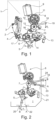
- FIG. 1 is a three-dimensional view of a motor vehicle lock 1, with only the components necessary to explain the invention being shown. Shown is a locking device 2 with a rotary latch 3 and a pawl 4, which are, for example, pivotably accommodated in a lock plate, not shown, of the motor vehicle lock 1.
- the locking mechanism 2 is shown in a main locking position in which the pawl 4 is Rotary movement of the rotary latch blocks, so that a lock holder, also not shown, can be fixed.
- the pawl 4 can interact with the pawl 4 by means of a release lever 5 and in particular by means of a pivoting movement of the release lever 5 in the direction of arrow P1 and release the pawl 4 from engagement with the rotary latch 3.
- the release lever 5 is accommodated in the motor vehicle lock 1 so that it can pivot about the axis 6.
- An actuating element 7 interacts with the release lever 5, the actuating element 7 being part of a drive unit 8 for actuating the release lever 5.
- the drive unit 8 has an electric motor 9, a drive wheel 10, a driven wheel 11 and the actuating element 7.
- a first gear stage is formed by the drive wheel 10 and the driven gear 11 and a second gear stage by the driven gear 11 and the actuating element 7.
- the first gear stage 10, 11 can be driven by means of the electric motor 9, which in turn causes the actuating element 7 to move around the axis 12 is pivotable.
- an operating lever 13 is shown, which is, for example, an external operating lever 13.
- the release lever 5 can also be pivoted in the direction of arrow P1, so that the locking mechanism 2 can be unlocked.
- the exemplary embodiment shown shows an actuating lever 14 which actuates the release lever 5 by means of a clutch lever 14 and with the aid of a control lever 15.
- the locking mechanism 2 can be unlocked manually using the external operating lever 13.
- a manual unlocking of the locking mechanism 2 is only necessary in a purely electrically operated motor vehicle lock 1 if a mechanical unlocking of the locking mechanism 2 is required.
- the actuating element 7 is pivoted in the direction of the arrow P2 by means of the first and second gear stages.
- a control cam 16 engages in the release lever 5 and pivots the release lever in the direction of arrow P1.
- One actuation end 17 of the release lever 5 thus comes into engagement with the pawl 4, the pawl 4 being pivoted in the direction of arrow P3.
- the pawl 4 disengages from the rotary latch 3, so that a lock holder held by the rotary latch 3 is released.
- the vehicle lock is now open. If the electrical power supply fails in this state of the motor vehicle lock 1, the lock 2 cannot be closed again. An electromechanical reset of the drive unit 8 cannot be carried out.
- means for resetting 18 are provided in the motor vehicle lock 1, with an extension 18 on the actuating element 7 being shown as an example.
- the control element 7 can be manually pivoted clockwise around the axis 12.
- a Bowden cable can engage in an engagement contour 19 of the extension 18 and pivot the adjusting element 7 or reset it manually.
- the actuating lever 13 and the release lever 5 is now shown, the position of the release lever 5 being shown in which the release lever 5 has unlocked the locking mechanism 2.
- the release lever 5 was pivoted from an initial position A into an actuation position B by the angle ⁇ .
- the extension 20 formed on the release lever 5 protrudes from the housing 21 of the motor vehicle lock 1, so that the extension 2 can be grasped manually.
- the housing 21 can have an opening 22 through which the means for resetting 20 extends.
- the extension 20 is connected and shown to the release lever 5 only as an example, imaginable and also in the Figure 2 The connection of an extension 18 to the actuating element 7 is shown.
- actuating element 7 If the actuating element 7 is returned to the starting position by means of the extension 18, a positive engagement between the actuating element 7 and the release lever 5 can be provided, so that the release lever 5 is reset mechanically and in a positively guided manner.
- the release lever 5 and the pawl 4 are reset by means of a spring provided on the release lever and/or on the pawl. After manually resetting the release lever 5, the locking mechanism 2 can be closed, so that the motor vehicle lock can be closed even in the event of a power failure.
Description
Die Erfindung betrifft ein elektrisch betätigbares Kraftfahrzeugschloss aufweisend ein Gesperre mit einer Drehfalle und mindestens einer Sperrklinke, einem Auslösehebel, wobei der Auslösehebel derart mit dem Gesperre zusammenwirkt, dass ein gesperrtes Gesperre entsperrbar ist, einer elektrischen Antriebseinheit, wobei der Auslösehebel zumindest mittels der Antriebseinheit betätigbar ist und die Antriebseinheit zumindest ein Stellelement zur Betätigung des Auslösehebels aufweist.The invention relates to an electrically operable motor vehicle lock having a lock with a rotary latch and at least one pawl, a release lever, the release lever interacting with the lock in such a way that a locked lock can be unlocked, an electric drive unit, the release lever being actuable at least by means of the drive unit and the drive unit has at least one actuating element for actuating the release lever.
Kraftfahrzeugtürschlösser mit einem elektrischen Antrieb zum Auslösen des Gesperres sind aus der Praxis in vielfältiger Ausgestaltung bekannt. Dabei sorgt der elektrische Antrieb dafür, dass ein Stellelement bewegt wird, mittels dem der Auslösehebel betätigt und somit das Gesperre entsperrt wird. Daneben lässt sich das Gesperre in den meisten Fällen grundsätzlich auch mechanisch öffnen. Das kann beispielsweise über einen Innenbetätigungshebel erfolgen. Demgegenüber sorgt ein meistens vom Außentürgriff beaufschlagter Sensor dafür, dass der elektrische Antrieb angesteuert wird. Durchaus in der Praxis üblich ist es auch, dass ein im Bereich des Außentürgriffs oder im Außentürgriff selbst angeordneter Sensor lediglich initialisiert werden muss, um den elektrischen Antrieb in Betrieb zu setzen.Motor vehicle door locks with an electric drive for triggering the locking mechanism are known from practice in a variety of designs. The electric drive ensures that an actuating element is moved, which activates the release lever and thus unlocks the locking mechanism. In addition, in most cases the lock can also be opened mechanically. This can be done, for example, using an internal operating lever. In contrast, a sensor, which is usually acted upon by the outside door handle, ensures that the electric drive is activated. It is also quite common in practice that a sensor arranged in the area of the outside door handle or in the outside door handle itself only needs to be initialized in order to put the electric drive into operation.
Allerdings besteht bei elektrischen Antrieben und insbesondere Öffnungsantrieben für das Gesperre und der zwischengeschalteten Betätigungshebelkette zwischen dem fraglichen elektrischen Antrieb und dem Gesperre das Problem, dass der Antrieb beispielsweise nach einem elektrischen Öffnungsvorgang nicht mehr in seine Grundstellung gebracht werden kann. Hierzu mag ein Ausfall der elektrischen Energieversorgung des elektrischen Antriebs gehören. Alternativ oder zusätzlich kann aber auch schlicht und ergreifend die Betätigungshebelkette mechanisch schwergängig und/oder blockiert sein.However, with electric drives and in particular opening drives for the locking mechanism and the intermediate actuating lever chain between the electric drive in question and the locking mechanism, there is the problem that the drive can no longer be brought into its basic position after an electrical opening process, for example. This may include a failure of the electrical energy supply to the electric drive. Alternatively or additionally, the actuating lever chain can simply be mechanically difficult to move and/or blocked.
In den genannten Fällen führt dies dazu, dass die Sperrklinke mit Hilfe der Betätigungshebelkette bzw. eines Auslösehebels als Bestandteil derselben in der ausgehobenen Stellung verbleibt. Die Drehfalle ist geöffnet und das Gesperre kann nicht geschlossen werden, weil die Sperrklinke aufgrund ihrer ausgehobenen Position nicht in die Drehfalle beim Schließvorgang einfallen kann.In the cases mentioned, this results in the pawl remaining in the raised position with the help of the actuating lever chain or a release lever as part of the same. The rotary latch is open and the lock cannot be closed because the pawl cannot fall into the rotary latch during the closing process due to its raised position.
In der
Aus der
Aus der
Aus der
Aus der
Der Stand der Technik liefert Ansätze dahingehend, dass die Betätigungshebelkette in einem Fall eines Stromausfalls auszukuppeln ist, wobei auch mit Hilfe eines manuell beaufschlagbaren Notbetätigungselements ein Schließen des Gesperres ermöglicht wird. Die Lösungen sind sämtlichst an zusätzliche Mechaniken gebunden und bedingen zumindest bereichsweise ein elektrisches Zurückstellen der Betätigungshebelkette, um die Schließmechanik wieder in ihre Ausgangslage zurückzuführen. Hier setzt die Erfindung an.The prior art provides approaches to the effect that the actuating lever chain is to be disengaged in the event of a power failure, with the aid of a manually actuated emergency actuating element also making it possible to close the locking mechanism. The solutions are all tied to additional mechanics and require an electrical reset, at least in some areas the operating lever chain to return the locking mechanism to its original position. This is where the invention comes into play.
Ausgehend von dem bekannten Stand der Technik stellt sich die Aufgabe, ein verbessertes Kraftfahrzeugschloss zur Verfügung zu stellen. Insbesondere stellt sich die Aufgabe, ein vereinfachtes mit einer geringeren Anzahl an Bauteilen versehenes Kraftfahrzeugschloss bereitzustellen, um eine Notschließung mit möglichst geringem Aufwand und unter Berücksichtigung einer konstruktiv einfachen Gestaltung und manueller Beaufschlagung zu ermöglichen.Based on the known prior art, the task is to provide an improved motor vehicle lock. In particular, the task is to provide a simplified motor vehicle lock with a smaller number of components in order to enable emergency closing with as little effort as possible and taking into account a structurally simple design and manual loading.
Die Lösung der Aufgabe erfolgt erfindungsgemäß durch die Merkmale des unabhängigen Anspruchs. Vorteilhafte Ausgestaltungen der Erfindung sind in den Unteransprüchen angegeben. Es wird darauf hingewiesen, dass die im Folgenden beschriebenen Ausführungsbeispiele nicht beschränkend sind, es sind vielmehr beliebige Variationsmöglichkeiten der in der Beschreibung und den Unteransprüchen sowie den Figuren beschriebenen Merkmale möglich.The problem is solved according to the invention by the features of the independent claim. Advantageous embodiments of the invention are specified in the subclaims. It should be noted that the exemplary embodiments described below are not restrictive; rather, any possible variation of the features described in the description and the subclaims as well as the figures are possible.
Gemäß dem Patentanspruch 1 wird die Aufgabe der Erfindung dadurch gelöst, dass ein elektrisch betätigbares Kraftfahrzeugschloss bereitgestellt wird, aufweisend ein Gesperre mit einer Drehfalle und mindestens einer Sperrklinke, einem Auslösehebel, wobei der Auslösehebel derart mit dem Gesperre zusammenwirkt, dass ein gesperrtes Gesperre entsperrbar ist, einer elektrischen Antriebseinheit, wobei der Auslösehebel zumindest mittels der Antriebseinheit betätigbar ist und die Antriebseinheit zumindest ein Stellelement zur Betätigung des Auslösehebels aufweist, und wobei das Kraftfahrzeugschloss ein Mittel zum manuellen Zurückstellen des betätigten Auslösehebels oder der betätigten Antriebseinheit, insbesondere eines Getriebes, aufweist. Durch den erfindungsgemäßen Aufbau des elektrisch betätigbaren Kraftfahrzeugschlosses ist nun die Möglichkeit gegeben, die Betätigungshebelkette und insbesondere die elektrische Antriebseinheit unmittelbar manuell in ihre Ausgangsstellung zurück zu überführen. Durch den unmittelbaren Eingriff auf die Betätigungskette zum Bewegen des Auslösehebels kann auf zusätzliche Bauteile verzichtet werden, so dass mit einer minimalen Anzahl von Bauteilen und somit konstruktiv günstig und kostengünstig ein Mittel zum Zurückstellen der elektrischen Antriebseinheit gegeben ist. Das Mittel zum manuellen Zurückstellen wirkt dabei derart auf den Antriebsstrang bzw. auf den Auslösehebel, dass die gesamte Betätigungskette in ihre Ausgangsstellung zurückgeführt wird.According to
Wird im Sinne der Erfindung von einem elektrisch betätigbaren Kraftfahrzeugschloss gesprochen, so sind damit auch solche Schlösser gemeint, die in Türen, Schiebetüren, Klappen und/oder Abdeckungen im Kraftfahrzeug zum Einsatz kommen, eben überall dort, wo schwenkbeweglich oder verschieblich am Kraftfahrzeug angebrachte Bauteile in ihrer Lage gesichert gehalten werden müssen. Bevorzugt bezieht sich das erfindungsgemäße elektrisch betätigbare Kraftfahrzeugschloss auf ein Seitentürschloss. Wird im Weiteren von einem Kraftfahrzeugschloss gesprochen, so stehen hierbei Synonyme wie Schließvorrichtung oder Türverschluss gleichbedeutend nebeneinander. Derartige Kraftfahrzeugschlösser umfassen ein Gesperre bestehend aus Drehfalle und Sperrklinke.When speaking of an electrically actuated motor vehicle lock in the context of the invention, this also means locks that are used in doors, sliding doors, flaps and/or covers in the motor vehicle, wherever components attached to the motor vehicle are pivotable or displaceable their location must be kept secure. The electrically operable motor vehicle lock according to the invention preferably relates to a side door lock. If we talk about a motor vehicle lock in the following, synonyms such as locking device or door lock are synonymous next to each other. Such motor vehicle locks include a locking mechanism consisting of a rotary latch and a pawl.
Das Gesperre kann darüber hinaus auch mit zwei oder mehr Sperrklinken ausgestattet sein oder beispielsweise einen Rast- oder Blockadehebel aufweisen. Eine erste Rastklinke, die auch als Komfortklinke bezeichnet wird, steht unmittelbar mit der Drehfalle in Eingriff. Je nach Auslegung des Gesperres kann im Gesperre eine Vorrast und/oder eine Hauptrast realisiert sein. Ist in der Hauptrastposition ein öffnendes Moment vorhanden, das heißt die Sperrklinke wird aufgrund der Kraft aus der Drehfalle in eine öffnende Position gedrängt, so kommt eine zweite Sperrklinke zum Einsatz, die auch als Rast- oder Blockadehebel bezeichenbar ist. Die zweite Sperrklinke sichert die erste Sperrklinke in ihrer Hauptrastposition. Im Falle eines Zweiklinkengesperres wirkt der Auslösehebel auf die zweite Sperrklinke oder die erste und zweite Sperrklinke. Der Auslösehebel wirkt dabei derart mit der oder den Sperrklinken zusammen, dass die Drehfalle freikommt und ein beispielsweise gehaltener Schlosshalter freigegeben wird. In der Freigabestellung wird die Sperrklinke oder werden die Sperrklinken außer Eingriff mit der Drehfalle gehalten. Genau in diesem Fall, in dem die Sperrklinke außer Eingriff mit der Drehfalle gehalten wird, kann es zu einem Ausfall der elektrischen Stromversorgung kommen, so dass das Gesperre nicht wieder verrastbar ist. Erfindungsgemäß kann nun der Auslösehebel manuell zurückgestellt werden.The locking mechanism can also be equipped with two or more pawls or, for example, have a locking or blocking lever. A first locking pawl, which is also referred to as a comfort pawl, is directly engaged with the rotary latch. Depending on the design of the locking mechanism, a preliminary detent and/or a main detent can be implemented in the locking mechanism. If there is an opening moment in the main locking position, i.e. the pawl is pushed into an opening position due to the force from the rotary latch, a second pawl is used, which can also be referred to as a locking or blocking lever. The second pawl secures the first pawl in its main locking position. In the case of a two-pawl lock, the release lever acts on the second pawl or the first and second pawls. The release lever interacts with the pawl or pawls in such a way that the rotary latch is released and a lock holder, for example, is released. In the release position, the pawl or pawls are held out of engagement with the rotary latch. Exactly in this case, where the pawl is disengaged from the If the rotary latch is held, the electrical power supply may fail, so that the locking mechanism cannot be locked again. According to the invention, the release lever can now be reset manually.
Die Antriebseinheit weist einen elektrischen Motor, insbesondere einen elektrischen Gleichstrommotor, auf, auf dessen Abtriebswelle ein Zahnrad angeordnet ist, welches bevorzugt mit einem Abtriebsrad zusammenwirkt. Bevorzugt kommen hier Zahnradgetriebe zum Einsatz, wobei die Erfindung nicht auf, zum Beispiel ein Schneckenradgetriebe begrenzt ist. Vorstellbar ist es vielmehr, dass mittels des elektrischen Antriebs auch andere Getriebearten, wie beispielsweise eine Zahnstange, bewegbar ist. Mittels der Motorgetriebeeinheit ist ein Stellelement bewegbar, wobei das Stellelement auch ein Teil des Getriebes sein kann. Bevorzugt ist das Stellelement als separates Bauteil ausgebildet und wird mittels einer Getriebestufe angetrieben. Dabei wird mittels des Stellelements der Auslösehebel bewegt, bevorzug verschwenkt. Der Ausfall der elektrischen Spannungsversorgung wirkt dabei derart, dass die Motorgetriebeeinheit ein Zurückstellen des Auslösehebel verhindern kann. Darüber hinaus kann auch beispielsweise ein Schwergängigkeit der Motorgetriebeeinheit und/oder des Stellelements und/oder des Auslösehebels ein Zurückstellen des Auslösehebels behindern. Bevorzugt sind die Bestandteile der Antriebskette für den Auslösehebel federvorgespannt, so dass ein Zurückstellen federunterstützt vorgenommen wird. Insbesondere ist die Sperrklinke bzw. sind die Sperrklinken federvorgespannt im Kraftfahrzeugschloss aufgenommen, so dass ein Zurückstellen des Auslösehebels unterstützbar ist. Auch der Auslösehebel, wie auch das Stellelement können federunterstützt im Kraftfahrzeugschloss aufgenommen sein.The drive unit has an electric motor, in particular an electric direct current motor, on the output shaft of which a gear is arranged, which preferably cooperates with an output gear. Gear transmissions are preferably used here, although the invention is not limited to, for example, a worm gear transmission. Rather, it is conceivable that other types of gears, such as a rack, can also be moved using the electric drive. An actuating element can be moved by means of the motor transmission unit, whereby the actuating element can also be part of the transmission. The actuating element is preferably designed as a separate component and is driven by means of a gear stage. The release lever is moved, preferably pivoted, by means of the actuating element. The failure of the electrical power supply has the effect that the motor gear unit can prevent the release lever from being reset. In addition, for example, stiffness of the motor transmission unit and/or the actuating element and/or the release lever can prevent the release lever from being reset. The components of the drive chain for the release lever are preferably spring-loaded, so that resetting is carried out with spring support. In particular, the pawl or pawls are spring-loaded in the motor vehicle lock, so that resetting the release lever can be supported. The release lever and the actuating element can also be accommodated in the motor vehicle lock in a spring-supported manner.
Eine weitere Ausgestaltungsvariante der Erfindung ergibt sich dann, wenn mittels des Mittels zum Zurückstellen das Stellelement betätigbar, insbesondere verschwenkbar ist. Das Stellelement ist Bestandteil der elektrischen Antriebseinheit und kann als einteiliges Bauteil gemeinsam mit einem Abtriebsrad einer Getriebestufe ausgebildet sein. Bevorzugt ist das Stellelement als separates Bauteil im Kraftfahrzeugschloss aufgenommen und bevorzugt schwenkbar im Kraftfahrzeugschloss gelagert. In der bevorzugten Ausführungsform besteht somit die Antriebseinheit und folglich die Betätigungskette für den Auslösehebel aus dem Elektromotor, einem auf der Abtriebswelle befestigten Antriebszahnrad, einem mit dem Antriebszahnrad kämmenden Abtriebsrad und dem Stellelement. Abtriebsrad und Stellelement können dabei über eine weitere Verzahnung und somit eine weitere Getriebestufe miteinander in Eingriff stehen. Wird folglich der Antriebsmotor bestromt, so wird das Stellelement über zwei Getriebestufen angetrieben und verschwenkt. Dies bietet den Vorteil, dass die Kraft, die in das Stellelement eingeleitet wird, an die Kräfte im Gesperre bzw. die Kräfte, die im Auslösehebel bereitzustellen sind, einstellbar sind. Wird beispielsweise ein Zweiklinkengesperre eingesetzt, so sind die Auslösekräfte, die auf die zweite Sperrklinke wirken, wesentlich geringer, als wenn ein Einklinkengesperre zum Einsatz kommt, wobei die Sperrklinke aus einer Rastposition heraus und aus dem Eingriff der Drehfalle herausbewegt werden muss. Das Verschwenken bzw. das drehbare oder schwenkbare Lagern des Stellelements bietet dabei eine konstruktiv günstige Möglichkeit, den Auslösehebel zu betätigen. Wirkt nun das Mittel zum Zurückstellen unmittelbar auf das Stellelement, so kann die Antriebskette vollumfänglich zurückgestellt werden. Ein Betätigen des Stellelements wirkt dabei über die Getriebestufen auf den Elektromotor und gleichzeitig auf den Auslösehebel. Der Auslösehebel und/oder die Sperrklinken können federvorgespannt vorliegen, so dass bei einem Zurückstellen des Stellelements sich die Sperrklinke und der Auslösehebel selbständig zurückbewegt. Es ist aber auch vorstellbar, dass das Stellelement formschlüssig mit dem Auslösehebel in Eingriff steht, so dass der Auslösehebel zurückführbar ist.A further embodiment variant of the invention results when the actuating element can be actuated, in particular pivoted, by means of the reset means. The actuating element is part of the electric drive unit and can be designed as a one-piece component together with a driven gear of a gear stage. The actuating element is preferably accommodated as a separate component in the motor vehicle lock and is preferably pivotable in the motor vehicle lock stored. In the preferred embodiment, the drive unit and consequently the actuation chain for the release lever consist of the electric motor, a drive gear attached to the output shaft, an output gear meshing with the drive gear and the actuating element. The driven gear and the actuating element can engage with each other via further toothing and thus a further gear stage. If the drive motor is therefore energized, the actuating element is driven and pivoted via two gear stages. This offers the advantage that the force that is introduced into the actuating element can be adjusted to the forces in the locking mechanism or the forces that are to be provided in the release lever. For example, if a two-pawl lock is used, the triggering forces that act on the second pawl are significantly lower than if a single pawl lock is used, whereby the pawl has to be moved out of a locking position and out of the engagement of the rotary latch. The pivoting or the rotatable or pivotable mounting of the actuating element offers a structurally favorable option for actuating the release lever. If the means for resetting now acts directly on the actuating element, the drive chain can be fully reset. Actuating the actuating element acts on the electric motor via the gear stages and at the same time on the release lever. The release lever and/or the locking pawls can be spring-loaded, so that when the actuating element is reset, the locking pawl and the release lever move back independently. However, it is also conceivable that the actuating element engages in a form-fitting manner with the release lever, so that the release lever can be returned.
In einer weiteren Ausgestaltungsvariante ist mittels des Mittels zum Zurückstellen der Auslösehebel betätigbar, insbesondere verschwenkbar. Der Auslösehebel wird bevorzugt elektrisch betätigt, indem die Antriebskette elektrisch bestromt und der Elektromotor das Stellelement derart bewegt, dass der Auslösehebel bewegt wird. Der Auslösehebel wirkt unmittelbar auf das Gesperre und entsperrt das Gesperre, wie vorstehend beschrieben. Der Auslösehebel kann je nach Ausführungsform des Gesperres aber auch manuell, zum Beispiel über einen Türaußengriff oder einen Türinnengriff betätigbar sein. Dazu kann der Auslösehebel mit einem Betätigungshebel in Eingriff gelangen. Ist das Mittel zum Zurückstellen unmittelbar am Auslösehebel befestigt, so kann bei einem ausgelenkten Rast- oder Blockadehebel und/oder einer Sperrklinke der Auslösehebel selbst manuell zurückgestellt werden. Somit kann das Gesperre wieder verrastet werden und eine Notschließung wird ermöglicht. Vorstellbar ist es aber auch, dass der Auslösehebel formschlüssig mit dem Stellelement zusammenwirkt, so dass bei einem Zurückstellen des Auslösehebels das Stellelement oder Stellelement und die Getriebestufen zurückstellbar sind. Die schwenkbewegliche Aufnahme des Auslösehebels bietet dabei den Vorteil einer kompakten Bauform und einer günstigen Möglichkeit, um Kräfte und/oder Momente in das Gesperre einzuleiten.In a further embodiment variant, the release lever can be actuated, in particular pivoted, by means of the means for resetting. The release lever is preferably actuated electrically by electrically energizing the drive chain and the electric motor moves the actuating element in such a way that the release lever is moved. The release lever acts directly on the locking mechanism and unlocks the locking mechanism as described above. Depending on the embodiment of the locking mechanism, the release lever can also be operated manually, for example via an outside door handle or an inside door handle. For this purpose, the release lever can be equipped with an operating lever get involved. If the means for resetting is attached directly to the release lever, the release lever itself can be reset manually if the locking or blocking lever and/or a pawl is deflected. This means that the locking mechanism can be locked again and an emergency closure is made possible. However, it is also conceivable that the release lever interacts in a form-fitting manner with the actuating element, so that when the release lever is reset, the actuating element or actuating element and the gear stages can be reset. The pivoting mount of the release lever offers the advantage of a compact design and a favorable option for introducing forces and/or moments into the locking mechanism.
Ist das Mittel zum Zurückstellen als Betätigungsnuss ausgeführt, so ergibt sich eine nicht erfindungsgemäße Variante.If the means for resetting is designed as an actuation nut, this results in a variant not according to the invention.
Als Betätigungsnuss sind allgemein mechanische Eingriffsmittel bekannt, die mittels eines Verdrehens eine mechanische Betätigung in das Kraftfahrzeugschloss einleiten können. Bevorzugt weisen diese Betätigungsnüsse Eingriffskonturen auf, die beispielsweise schlitzförmig oder als Vierkant oder Sechskant ausgeführt sein können. Bevorzugt sind die Eingriffsöffnungen schlitzförmig ausgeführt, so dass ein Bediener beispielsweise einen Schlüssel oder einen Schraubenzieher in den Schlitz einführen können, um die Betätigungsnuss, die auch Schaltnuss heißen kann, zu betätigen. Die Betätigungsnuss ist im eingebauten Zustand des Kraftfahrzeugschlosses von einer inneren Oberfläche, beispielsweise im Bereich der B-Säule, aus zugänglich. Durch ein Verdrehen oder Verschieben der Betätigungsnuss kann die Antriebseinheit, das Stellelement oder der Auslösehebel mittelbar oder unmittelbar mechanisch zurückgestellt werden. Hierzu kann an die Betätigungsnuss eine Hebelmechanik und/oder eine zusätzliche Getriebeeinheit angebunden sein, um den Auslösehebel wieder in seine Ausgangsstellung zurückzuüberführen.Mechanical engagement means are generally known as actuation nut, which can initiate a mechanical actuation in the motor vehicle lock by twisting. These actuation nuts preferably have engagement contours which can, for example, be slot-shaped or designed as a square or hexagon. The engagement openings are preferably designed to be slot-shaped, so that an operator can, for example, insert a key or a screwdriver into the slot in order to operate the actuation nut, which can also be called a switching nut. When the motor vehicle lock is installed, the actuation nut is accessible from an inner surface, for example in the area of the B-pillar. By turning or moving the actuating nut, the drive unit, the actuating element or the release lever can be mechanically reset directly or indirectly. For this purpose, a lever mechanism and/or an additional gear unit can be connected to the actuation nut in order to return the release lever to its starting position.
Bevorzugt ist die Betätigungsnuss im Bereich des Einlaufmauls des Kraftfahrzeugschlosses angeordnet.The actuation nut is preferably arranged in the area of the inlet mouth of the motor vehicle lock.
Das Einlaufmaul ist der Bereich des Kraftfahrzeugschlosses, durch den hindurch das Kraftfahrzeugschloss mit einem Schlosshalter zusammenwirkt. Im geöffneten Zustand des Kraftfahrzeugschlosses gibt die Drehfalle das Einlaufmaul im Wesentlichen frei, so dass ein Zugang des Schlosshalters zur Drehfalle möglich ist. Die Anordnung der Betätigungsnuss im Bereich des Einlaufmauls bietet somit in vorteilhafter Weise einen Zugang zum Kraftfahrzeugschloss, ohne weitere Öffnungen im Kraftfahrzeug zur Betätigung der Betätigungsnuss anordnen zu müssen.The inlet mouth is the area of the motor vehicle lock through which the motor vehicle lock interacts with a lock holder. When the motor vehicle lock is open, the rotary latch essentially releases the inlet mouth, so that the lock holder can access the rotary latch. The arrangement of the actuation nut in the area of the inlet mouth thus advantageously offers access to the motor vehicle lock without having to arrange further openings in the motor vehicle for actuating the actuation nut.
Erfindungsgemäß ist das Mittel zum Zurückstellen als Verlängerung, insbesondere als hebelartige Verlängerung, am Stellelement oder am Auslösehebel ausgebildet.According to the invention, the means for resetting is designed as an extension, in particular as a lever-like extension, on the actuating element or on the release lever.
Die unmittelbare Verlängerung der Bestandteile des Kraftfahrzeugschlosses, wie Stellelement oder Auslösehebel, bietet den Vorteil, dass auf vorhandene Bestandteile des Kraftfahrzeugschlosses zurückgegriffen werden kann. Durch eine ledigliche Verlängerung der Bestandteile kann die Anzahl der benötigten Bauteile auf ein Minimum reduziert werden. Dabei ist es auch vorstellbar, dass die Verlängerung ein manuelles Eingriffsmittel für den Benutzer des Kraftfahrzeugs bildet. Dabei kann die Verlängerung beispielsweise aus dem Kraftfahrzeugschloss herausragen und manuell vom Bediener ergriffen und betätigt werden. Somit kann eine Notbetätigung, das heißt ein Zurückstellen des Auslösehebels, unmittelbar durch das Betätigen des Stellelements oder des Auslösehebels erfolgen. Nach einer Betätigung der Verlängerung befindet sich der Auslösehebel wieder in seiner Ausgangslage, so dass die Sperrklinke federgetrieben wieder in Eingriff mit der Drehfalle bringbar ist.The direct extension of the components of the motor vehicle lock, such as the adjusting element or release lever, offers the advantage that existing components of the motor vehicle lock can be used. By simply extending the components, the number of components required can be reduced to a minimum. It is also conceivable that the extension forms a manual intervention means for the user of the motor vehicle. The extension can, for example, protrude from the motor vehicle lock and be gripped and operated manually by the operator. An emergency operation, i.e. resetting the release lever, can therefore be carried out directly by actuating the actuating element or the release lever. After activating the extension, the release lever is back in its starting position, so that the spring-driven pawl can be brought back into engagement with the rotary latch.
Vorteilhaft kann es auch sein, wenn das Mittel zum Zurückstellen mittelbar, insbesondere über ein flexibles Betätigungselement, betätigbar ist. Ein flexibles Betätigungsmittel kann beispielsweise ein Bowdenzug oder ein Zugseil sein, das vom Bediener zur Notbetätigung ergriffen und gezogen oder gedrückt werden kann. Durch den Einsatz eines flexiblen Betätigungselements besteht die Möglichkeit, die Notbetätigung beabstandet vom Kraftfahrzeugschloss anzuordnen, so dass eine vorteilhafte und für den Bediener gut sichtbare Anordnung der Notbetätigung im Kraftfahrzeugschloss ausbildbar ist.It can also be advantageous if the means for resetting can be actuated indirectly, in particular via a flexible actuating element. A flexible actuation means can be, for example, a Bowden cable or a pull rope that can be grasped and pulled or pushed by the operator for emergency operation. By using a flexible actuating element, it is possible to arrange the emergency actuation at a distance from the motor vehicle lock, so that an advantageous arrangement of the emergency actuation in the motor vehicle lock that is clearly visible to the operator can be formed.
Durch den erfindungsgemäßen Aufbau des Kraftfahrzeugschlosses besteht nun die Möglichkeit, im Falle eines Stromausfalls und bei ausgelenkter Sperrklinke, den elektrischen Antrieb und den Auslösehebel zurückzustellen, so dass ein erneutes Verschließen des Kraftfahrzeugschlosses ermöglichbar ist. Auch wenn in den Beispielen nicht weiter ausgeführt, so besteht natürlich ebenso die Möglichkeit, ein Mittel zum Zurückstellen und beispielsweise eine Verlängerung auch an die Sperrklinke selbst anzuordnen, um den Auslösehebel und die Antriebseinheit zurückstellen zu können.The structure of the motor vehicle lock according to the invention now makes it possible to reset the electric drive and the release lever in the event of a power failure and when the pawl is deflected, so that the motor vehicle lock can be closed again. Even if not explained further in the examples, there is of course also the possibility of arranging a means for resetting and, for example, an extension on the pawl itself in order to be able to reset the release lever and the drive unit.
Nachfolgend wird die Erfindung unter Bezugnahme auf die anliegenden Zeichnungen anhand verschiedener Ausführungsbeispiele näher erläutert. Es gilt jedoch der Grundsatz, dass das Ausführungsbeispiel die Erfindung nicht beschränkt, sondern lediglich eine vorteilhafte Ausgestaltungsform darstellt.The invention is explained in more detail below with reference to the accompanying drawings using various exemplary embodiments. However, the principle applies that the exemplary embodiment does not limit the invention, but merely represents an advantageous embodiment.
Es zeigt:
-
Figur 1 -
Figur 2
-
Figure 1 a three-dimensional view of a motor vehicle lock, with only the components essential for explaining the invention being shown; and -
Figure 2 a side view of the drive unit, the actuation mechanism and the release lever.
In der
Die Sperrklinke 4 kann mittels eines Auslösehebels 5 und insbesondere mittels einer Schwenkbewegung des Auslösehebels 5 in Richtung des Pfeils P1 mit der Sperrklinke 4 zusammenwirken und die Sperrklinke 4 aus dem Eingriff mit der Drehfalle 3 lösen. Dazu ist der Auslösehebel 5 um die Achse 6 herum schwenkbar im Kraftfahrzeugschloss 1 aufgenommen. Mit dem Auslösehebel 5 wirkt ein Stellelement 7 zusammen, wobei das Stellelement 7 Teil einer Antriebseinheit 8 zur Betätigung des Auslösehebels 5 ist. Die Antriebseinheit 8 weist einen Elektromotor 9, ein Antriebsrad 10, ein Abtriebsrad 11 und das Stellelement 7 auf. Eine erste Getriebestufe wird dabei durch das Antriebsrad 10 und das Abtriebsrad 11 gebildet und eine zweite Getriebestufe durch das Abtriebsrad 11 und das Stellelement 7. Mittels des Elektromotors 9 ist die erste Getriebestufe 10, 11 antreibbar, wodurch wiederum das Stellelement 7 um die Achse 12 herum schwenkbar ist.The
Zusätzlich ist in der
Wird nun die Antriebseinheit 8 und insbesondere der Elektromotor 9 bestromt, so wird das Stellelement 7 mittels der ersten und zweiten Getriebestufe in Richtung des Pfeils P2 verschwenkt. Dabei greift ein Steuernocken 16 in den Auslösehebel 5 ein und verschwenkt den Auslösehebel in Richtung des Pfeils P1. Ein Betätigungsende 17 des Auslösehebels 5 gelangt somit mit der Sperrklinke 4 in Eingriff, wobei die Sperrklinke 4 in Richtung des Pfeils P3 verschwenkt wird. Die Sperrklinke 4 gelangt mit der Drehfalle 3 außer Eingriff, so dass ein mittels der Drehfalle 3 gehaltener Schlosshalter freikommt. Das Kraftfahrzeugschloss liegt nun geöffnet vor. Kommt es in diesem Zustand des Kraftfahrzeugschlosses 1 dazu, dass die elektrische Stromversorgung ausfällt, so kann das Gesperre 2 nicht wieder geschlossen werden. Ein elektromechanisches Zurückstellen der Antriebseinheit 8 kann nicht durchgeführt werden. In diesem Fall sind Mittel zum Zurückstellen 18 im Kraftfahrzeugschloss 1 vorgesehen, wobei beispielhaft eine Verlängerung 18 am Stellelement 7 dargestellt ist. Mittels der Verlängerung 18 kann das Stellelement 7 im Uhrzeigersinn um die Achse 12 herum manuell verschwenkt werden. Dazu kann beispielsweise ein Bowdenzug in eine Eingriffskontur 19 der Verlängerung 18 eingreifen und das Stellelement 7 verschwenken bzw. manuell zurückstellen.If the
In der
Wird das Stellelement 7 mittels der Verlängerung 18 in die Ausgangslage zurück überführt, so kann ein formschlüssiger Eingriff zwischen dem Stellelement 7 und dem Auslösehebel 5 vorgesehen sein, so dass der Auslösehebel 5 mechanisch und zwangsgeführt zurückgestellt wird. Vorstellbar ist es aber auch, dass nach einem Zurückstellen des Stellelements 7 der Auslösehebel 5 und die Sperrklinke 4 mittels einer am Auslösehebel und/oder an der Sperrklinke vorgesehene Feder zurückgestellt wird. Nach dem manuellen Zurückstellen des Auslösehebels 5 kann das Gesperre 2 geschlossen werden, so dass auch im Fall eines Stromausfalls ein Schließen des Kraftfahrzeugschlosses ermöglichbar ist.If the
- 11
- KraftfahrzeugschlossMotor vehicle lock
- 22
- GesperreLock
- 33
- DrehfalleRotary trap
- 44
- Sperrklinkepawl
- 55
- AuslösehebelTrigger lever
- 6, 126, 12
- Achseaxis
- 77
- StellelementControl element
- 88th
- AntriebseinheitDrive unit
- 99
- ElektromotorElectric motor
- 1010
- Antriebsraddrive wheel
- 1111
- Abtriebsraddriven gear
- 1313
- BetätigungshebelOperating lever
- 1414
- KupplungshebelClutch lever
- 1515
- SteuerhebelControl lever
- 1616
- Steuernockencontrol cam
- 1717
- BetätigungsendeEnd of operation
- 18, 2018, 20
- Mittel zum Zurückstellen, VerlängerungMeans of deferral, extension
- 1919
- Eingriffskonturengagement contour
- 2121
- GehäuseHousing
- 22, 2322, 23
- Öffnungopening
- 2424
- Anschlagattack
- P1, P2, P3, P4P1, P2, P3, P4
- PfeilArrow
- AA
- AusgangslageInitial situation
- Bb
- BetätigungslageOperating position
- αα
- Winkelangle
Claims (7)
- Electrically actuatable motor vehicle latch (1) comprising a locking mechanism (2) having a catch (3) and at least one pawl (4), a release lever (5), the release lever (5) interacting with the locking mechanism (2) in such a way that a locked locking mechanism (2) can be unlocked, an electric drive unit (8), the release lever (5) being actuated at least by means of the drive unit (8), and the drive unit (8) having at least one control member (7) for actuating the release lever (5), the motor vehicle latch (1) having a means (18, 20) for resetting the actuated release lever (5) in order to allow an emergency closure, characterized in that
the resetting means (18, 20) is designed as an extension (18, 20), in particular as a lever-like extension (18, 20), on the control member (7) or on the release lever (5). - Motor vehicle latch (1) according to claim 1, characterized in that the control member (7) can be actuated, in particular pivoted, by means of the resetting means (18, 20).
- Motor vehicle latch (1) according to claim 1, characterized in that the release lever (5) can be actuated, in particular pivoted, by means of the resetting means (18, 20).
- Motor vehicle latch (1) according to any of claims 1 to 3,
characterized in that the extension (18, 20) has a manual engagement means (19), in particular an engagement contour (19). - Motor vehicle latch (1) according to any of claims 1 to 4,
characterized in that the resetting means (18, 20) is indirectly actuatable, in particular by means of a flexible actuation element. - Motor vehicle latch (1) according to any of claims 1 to 5,
characterized in that the control member (7) can be form-fittingly brought into engagement with the release lever (5). - Motor vehicle latch (1) according to any of claims 1 to 6,
characterized in that the control member (7) is designed as a separate component in the motor vehicle latch (1).
Applications Claiming Priority (2)
| Application Number | Priority Date | Filing Date | Title |
|---|---|---|---|
| DE102020102073.2A DE102020102073A1 (en) | 2020-01-29 | 2020-01-29 | Electrically operated motor vehicle lock |
| PCT/DE2021/100038 WO2021151423A1 (en) | 2020-01-29 | 2021-01-14 | Electrically actuatable motor vehicle lock |
Publications (2)
| Publication Number | Publication Date |
|---|---|
| EP4097318A1 EP4097318A1 (en) | 2022-12-07 |
| EP4097318B1 true EP4097318B1 (en) | 2024-03-06 |
Family
ID=74235993
Family Applications (1)
| Application Number | Title | Priority Date | Filing Date |
|---|---|---|---|
| EP21701649.2A Active EP4097318B1 (en) | 2020-01-29 | 2021-01-14 | Electrically actuatable motor vehicle lock |
Country Status (4)
| Country | Link |
|---|---|
| US (1) | US20230074045A1 (en) |
| EP (1) | EP4097318B1 (en) |
| DE (1) | DE102020102073A1 (en) |
| WO (1) | WO2021151423A1 (en) |
Families Citing this family (2)
| Publication number | Priority date | Publication date | Assignee | Title |
|---|---|---|---|---|
| DE102022122494A1 (en) | 2022-09-06 | 2024-03-07 | Kiekert Aktiengesellschaft | Motor vehicle lock, in particular motor vehicle door lock |
| DE102022122495A1 (en) | 2022-09-06 | 2024-03-07 | Kiekert Aktiengesellschaft | Motor vehicle lock, in particular motor vehicle door lock |
Family Cites Families (6)
| Publication number | Priority date | Publication date | Assignee | Title |
|---|---|---|---|---|
| DE10048709A1 (en) | 2000-09-30 | 2002-04-18 | Kiekert Ag | Vehicle door lock has electrical drive actuating locking mechanism and coupled to operating lever for emergency opening |
| EP2653639B1 (en) * | 2012-04-17 | 2014-09-24 | Magna Closures SpA | An electrical vehicle latch |
| DE102017123262A1 (en) * | 2017-10-06 | 2019-04-11 | Kiekert Ag | Motor vehicle door lock |
| DE102017124525A1 (en) * | 2017-10-20 | 2019-04-25 | Kiekert Ag | Motor vehicle door lock |
| DE102017124531A1 (en) * | 2017-10-20 | 2019-04-25 | Kiekert Ag | Motor vehicle door lock |
| DE102018110700A1 (en) | 2018-05-04 | 2019-11-07 | Kiekert Ag | Electrically actuated motor vehicle lock |
-
2020
- 2020-01-29 DE DE102020102073.2A patent/DE102020102073A1/en active Pending
-
2021
- 2021-01-14 WO PCT/DE2021/100038 patent/WO2021151423A1/en unknown
- 2021-01-14 US US17/799,032 patent/US20230074045A1/en active Pending
- 2021-01-14 EP EP21701649.2A patent/EP4097318B1/en active Active
Also Published As
| Publication number | Publication date |
|---|---|
| EP4097318A1 (en) | 2022-12-07 |
| US20230074045A1 (en) | 2023-03-09 |
| WO2021151423A1 (en) | 2021-08-05 |
| DE102020102073A1 (en) | 2021-07-29 |
Similar Documents
| Publication | Publication Date | Title |
|---|---|---|
| EP0917612B1 (en) | Motor vehicle door lock or the like | |
| EP1101890B1 (en) | Motor vehicle door lock | |
| EP4073335B1 (en) | Motor vehicle lock | |
| WO2019210905A1 (en) | Electrically actuable motor-vehicle lock | |
| DE19706657C2 (en) | Lock for a door of a vehicle | |
| DE102018113562A1 (en) | Electrically actuated motor vehicle lock | |
| DE60018746T2 (en) | LOCKING DEVICE | |
| EP1091061A2 (en) | Device for assisted opening of door locks | |
| EP3303742B1 (en) | Method of driving a vehicle door lock | |
| EP4097318B1 (en) | Electrically actuatable motor vehicle lock | |
| EP1045093A2 (en) | Lock for a motor vehicle door or the like | |
| EP1408187B1 (en) | Device for operating a lock for doors, flaps or similar, in particular on vehicles | |
| EP2133497B1 (en) | Vehicle door lock | |
| DE19924458B4 (en) | Motor vehicle door locking device | |
| DE19806154C2 (en) | Motor vehicle door lock | |
| WO2018006896A1 (en) | Motor vehicle lock | |
| DE10247842A1 (en) | Vehicle door lock has lock mechanism incorporating central locking arrangement, with adjusting element turning on axle, locking lever, unlocking lever and engaging elements | |
| DE19913590C2 (en) | Central locking system for a motor vehicle | |
| DE10042191A1 (en) | Motor vehicle door lock with controlled actuator element has coupling with associated control mechanism that engages coupling if inner or outer door handle is operated | |
| DE60121495T2 (en) | locking device | |
| DE10001435A1 (en) | Car door lock has for rapid unlocking, latch found in engagement with locking lever, preferably in its locking and/or thief-proof safety position | |
| EP0500062B1 (en) | Door locking device for passenger carrying vehicles | |
| WO2022057967A1 (en) | Opening apparatus for a motor vehicle door element | |
| DE102016112260A1 (en) | ELECTRICALLY ACTUATED MOTOR VEHICLE LOCK | |
| DE10339542B4 (en) | Motor vehicle door lock |
Legal Events
| Date | Code | Title | Description |
|---|---|---|---|
| STAA | Information on the status of an ep patent application or granted ep patent |
Free format text: STATUS: UNKNOWN |
|
| STAA | Information on the status of an ep patent application or granted ep patent |
Free format text: STATUS: THE INTERNATIONAL PUBLICATION HAS BEEN MADE |
|
| PUAI | Public reference made under article 153(3) epc to a published international application that has entered the european phase |
Free format text: ORIGINAL CODE: 0009012 |
|
| STAA | Information on the status of an ep patent application or granted ep patent |
Free format text: STATUS: REQUEST FOR EXAMINATION WAS MADE |
|
| 17P | Request for examination filed |
Effective date: 20220825 |
|
| AK | Designated contracting states |
Kind code of ref document: A1 Designated state(s): AL AT BE BG CH CY CZ DE DK EE ES FI FR GB GR HR HU IE IS IT LI LT LU LV MC MK MT NL NO PL PT RO RS SE SI SK SM TR |
|
| DAV | Request for validation of the european patent (deleted) | ||
| DAX | Request for extension of the european patent (deleted) | ||
| GRAP | Despatch of communication of intention to grant a patent |
Free format text: ORIGINAL CODE: EPIDOSNIGR1 |
|
| STAA | Information on the status of an ep patent application or granted ep patent |
Free format text: STATUS: GRANT OF PATENT IS INTENDED |
|
| INTG | Intention to grant announced |
Effective date: 20231013 |
|
| GRAS | Grant fee paid |
Free format text: ORIGINAL CODE: EPIDOSNIGR3 |
|
| GRAA | (expected) grant |
Free format text: ORIGINAL CODE: 0009210 |
|
| STAA | Information on the status of an ep patent application or granted ep patent |
Free format text: STATUS: THE PATENT HAS BEEN GRANTED |
|
| AK | Designated contracting states |
Kind code of ref document: B1 Designated state(s): AL AT BE BG CH CY CZ DE DK EE ES FI FR GB GR HR HU IE IS IT LI LT LU LV MC MK MT NL NO PL PT RO RS SE SI SK SM TR |
|
| REG | Reference to a national code |
Ref country code: CH Ref legal event code: EP |
|
| REG | Reference to a national code |
Ref country code: DE Ref legal event code: R096 Ref document number: 502021002905 Country of ref document: DE |
|
| REG | Reference to a national code |
Ref country code: IE Ref legal event code: FG4D Free format text: LANGUAGE OF EP DOCUMENT: GERMAN |