EP4096956B1 - Anzeigevorrichtung, kraftfahrzeug mit einer anzeigevorrichtung, und verfahren zum betreiben einer anzeigevorrichtung - Google Patents
Anzeigevorrichtung, kraftfahrzeug mit einer anzeigevorrichtung, und verfahren zum betreiben einer anzeigevorrichtung Download PDFInfo
- Publication number
- EP4096956B1 EP4096956B1 EP20838509.6A EP20838509A EP4096956B1 EP 4096956 B1 EP4096956 B1 EP 4096956B1 EP 20838509 A EP20838509 A EP 20838509A EP 4096956 B1 EP4096956 B1 EP 4096956B1
- Authority
- EP
- European Patent Office
- Prior art keywords
- display surface
- display
- display device
- clamping element
- clamping
- Prior art date
- Legal status (The legal status is an assumption and is not a legal conclusion. Google has not performed a legal analysis and makes no representation as to the accuracy of the status listed.)
- Active
Links
Images



Classifications
-
- B—PERFORMING OPERATIONS; TRANSPORTING
- B60—VEHICLES IN GENERAL
- B60R—VEHICLES, VEHICLE FITTINGS, OR VEHICLE PARTS, NOT OTHERWISE PROVIDED FOR
- B60R11/00—Arrangements for holding or mounting articles, not otherwise provided for
- B60R11/02—Arrangements for holding or mounting articles, not otherwise provided for for radio sets, television sets, telephones, or the like; Arrangement of controls thereof
- B60R11/0229—Arrangements for holding or mounting articles, not otherwise provided for for radio sets, television sets, telephones, or the like; Arrangement of controls thereof for displays, e.g. cathodic tubes
- B60R11/0235—Arrangements for holding or mounting articles, not otherwise provided for for radio sets, television sets, telephones, or the like; Arrangement of controls thereof for displays, e.g. cathodic tubes of flat type, e.g. LCD
-
- B—PERFORMING OPERATIONS; TRANSPORTING
- B60—VEHICLES IN GENERAL
- B60K—ARRANGEMENT OR MOUNTING OF PROPULSION UNITS OR OF TRANSMISSIONS IN VEHICLES; ARRANGEMENT OR MOUNTING OF PLURAL DIVERSE PRIME-MOVERS IN VEHICLES; AUXILIARY DRIVES FOR VEHICLES; INSTRUMENTATION OR DASHBOARDS FOR VEHICLES; ARRANGEMENTS IN CONNECTION WITH COOLING, AIR INTAKE, GAS EXHAUST OR FUEL SUPPLY OF PROPULSION UNITS IN VEHICLES
- B60K35/00—Instruments specially adapted for vehicles; Arrangement of instruments in or on vehicles
- B60K35/20—Output arrangements, i.e. from vehicle to user, associated with vehicle functions or specially adapted therefor
- B60K35/21—Output arrangements, i.e. from vehicle to user, associated with vehicle functions or specially adapted therefor using visual output, e.g. blinking lights or matrix displays
- B60K35/22—Display screens
-
- B—PERFORMING OPERATIONS; TRANSPORTING
- B60—VEHICLES IN GENERAL
- B60K—ARRANGEMENT OR MOUNTING OF PROPULSION UNITS OR OF TRANSMISSIONS IN VEHICLES; ARRANGEMENT OR MOUNTING OF PLURAL DIVERSE PRIME-MOVERS IN VEHICLES; AUXILIARY DRIVES FOR VEHICLES; INSTRUMENTATION OR DASHBOARDS FOR VEHICLES; ARRANGEMENTS IN CONNECTION WITH COOLING, AIR INTAKE, GAS EXHAUST OR FUEL SUPPLY OF PROPULSION UNITS IN VEHICLES
- B60K35/00—Instruments specially adapted for vehicles; Arrangement of instruments in or on vehicles
- B60K35/20—Output arrangements, i.e. from vehicle to user, associated with vehicle functions or specially adapted therefor
- B60K35/21—Output arrangements, i.e. from vehicle to user, associated with vehicle functions or specially adapted therefor using visual output, e.g. blinking lights or matrix displays
- B60K35/22—Display screens
- B60K35/223—Flexible displays
-
- B—PERFORMING OPERATIONS; TRANSPORTING
- B60—VEHICLES IN GENERAL
- B60K—ARRANGEMENT OR MOUNTING OF PROPULSION UNITS OR OF TRANSMISSIONS IN VEHICLES; ARRANGEMENT OR MOUNTING OF PLURAL DIVERSE PRIME-MOVERS IN VEHICLES; AUXILIARY DRIVES FOR VEHICLES; INSTRUMENTATION OR DASHBOARDS FOR VEHICLES; ARRANGEMENTS IN CONNECTION WITH COOLING, AIR INTAKE, GAS EXHAUST OR FUEL SUPPLY OF PROPULSION UNITS IN VEHICLES
- B60K35/00—Instruments specially adapted for vehicles; Arrangement of instruments in or on vehicles
- B60K35/50—Instruments characterised by their means of attachment to or integration in the vehicle
- B60K35/53—Movable instruments, e.g. slidable
-
- B—PERFORMING OPERATIONS; TRANSPORTING
- B60—VEHICLES IN GENERAL
- B60K—ARRANGEMENT OR MOUNTING OF PROPULSION UNITS OR OF TRANSMISSIONS IN VEHICLES; ARRANGEMENT OR MOUNTING OF PLURAL DIVERSE PRIME-MOVERS IN VEHICLES; AUXILIARY DRIVES FOR VEHICLES; INSTRUMENTATION OR DASHBOARDS FOR VEHICLES; ARRANGEMENTS IN CONNECTION WITH COOLING, AIR INTAKE, GAS EXHAUST OR FUEL SUPPLY OF PROPULSION UNITS IN VEHICLES
- B60K35/00—Instruments specially adapted for vehicles; Arrangement of instruments in or on vehicles
- B60K35/55—Instruments with parts that can change their shape or position to configure an active screen, e.g. by folding or by rolling
-
- B—PERFORMING OPERATIONS; TRANSPORTING
- B60—VEHICLES IN GENERAL
- B60K—ARRANGEMENT OR MOUNTING OF PROPULSION UNITS OR OF TRANSMISSIONS IN VEHICLES; ARRANGEMENT OR MOUNTING OF PLURAL DIVERSE PRIME-MOVERS IN VEHICLES; AUXILIARY DRIVES FOR VEHICLES; INSTRUMENTATION OR DASHBOARDS FOR VEHICLES; ARRANGEMENTS IN CONNECTION WITH COOLING, AIR INTAKE, GAS EXHAUST OR FUEL SUPPLY OF PROPULSION UNITS IN VEHICLES
- B60K35/00—Instruments specially adapted for vehicles; Arrangement of instruments in or on vehicles
- B60K35/60—Instruments characterised by their location or relative disposition in or on vehicles
-
- B—PERFORMING OPERATIONS; TRANSPORTING
- B60—VEHICLES IN GENERAL
- B60K—ARRANGEMENT OR MOUNTING OF PROPULSION UNITS OR OF TRANSMISSIONS IN VEHICLES; ARRANGEMENT OR MOUNTING OF PLURAL DIVERSE PRIME-MOVERS IN VEHICLES; AUXILIARY DRIVES FOR VEHICLES; INSTRUMENTATION OR DASHBOARDS FOR VEHICLES; ARRANGEMENTS IN CONNECTION WITH COOLING, AIR INTAKE, GAS EXHAUST OR FUEL SUPPLY OF PROPULSION UNITS IN VEHICLES
- B60K35/00—Instruments specially adapted for vehicles; Arrangement of instruments in or on vehicles
- B60K35/80—Arrangements for controlling instruments
-
- B—PERFORMING OPERATIONS; TRANSPORTING
- B60—VEHICLES IN GENERAL
- B60K—ARRANGEMENT OR MOUNTING OF PROPULSION UNITS OR OF TRANSMISSIONS IN VEHICLES; ARRANGEMENT OR MOUNTING OF PLURAL DIVERSE PRIME-MOVERS IN VEHICLES; AUXILIARY DRIVES FOR VEHICLES; INSTRUMENTATION OR DASHBOARDS FOR VEHICLES; ARRANGEMENTS IN CONNECTION WITH COOLING, AIR INTAKE, GAS EXHAUST OR FUEL SUPPLY OF PROPULSION UNITS IN VEHICLES
- B60K35/00—Instruments specially adapted for vehicles; Arrangement of instruments in or on vehicles
- B60K35/10—Input arrangements, i.e. from user to vehicle, associated with vehicle functions or specially adapted therefor
-
- B—PERFORMING OPERATIONS; TRANSPORTING
- B60—VEHICLES IN GENERAL
- B60K—ARRANGEMENT OR MOUNTING OF PROPULSION UNITS OR OF TRANSMISSIONS IN VEHICLES; ARRANGEMENT OR MOUNTING OF PLURAL DIVERSE PRIME-MOVERS IN VEHICLES; AUXILIARY DRIVES FOR VEHICLES; INSTRUMENTATION OR DASHBOARDS FOR VEHICLES; ARRANGEMENTS IN CONNECTION WITH COOLING, AIR INTAKE, GAS EXHAUST OR FUEL SUPPLY OF PROPULSION UNITS IN VEHICLES
- B60K37/00—Dashboards
-
- B—PERFORMING OPERATIONS; TRANSPORTING
- B60—VEHICLES IN GENERAL
- B60R—VEHICLES, VEHICLE FITTINGS, OR VEHICLE PARTS, NOT OTHERWISE PROVIDED FOR
- B60R11/00—Arrangements for holding or mounting articles, not otherwise provided for
- B60R2011/0042—Arrangements for holding or mounting articles, not otherwise provided for characterised by mounting means
- B60R2011/008—Adjustable or movable supports
- B60R2011/0082—Adjustable or movable supports collapsible, e.g. for storing after use
-
- B—PERFORMING OPERATIONS; TRANSPORTING
- B60—VEHICLES IN GENERAL
- B60R—VEHICLES, VEHICLE FITTINGS, OR VEHICLE PARTS, NOT OTHERWISE PROVIDED FOR
- B60R11/00—Arrangements for holding or mounting articles, not otherwise provided for
- B60R2011/0042—Arrangements for holding or mounting articles, not otherwise provided for characterised by mounting means
- B60R2011/008—Adjustable or movable supports
- B60R2011/0084—Adjustable or movable supports with adjustment by linear movement in their operational position
-
- B—PERFORMING OPERATIONS; TRANSPORTING
- B60—VEHICLES IN GENERAL
- B60R—VEHICLES, VEHICLE FITTINGS, OR VEHICLE PARTS, NOT OTHERWISE PROVIDED FOR
- B60R11/00—Arrangements for holding or mounting articles, not otherwise provided for
- B60R2011/0042—Arrangements for holding or mounting articles, not otherwise provided for characterised by mounting means
- B60R2011/008—Adjustable or movable supports
- B60R2011/0092—Adjustable or movable supports with motorization
Definitions
- the invention relates to a display device, i.e. a device, a device component or a device group, which is designed to display display contents.
- the display device comprises a flexible display surface element with a display surface for displaying the display content.
- the invention also relates to a motor vehicle with such a display device.
- Displays are increasingly finding their way into vehicles and are becoming design elements. There is a desire to have displays that are as large as possible and to be able to vary their size depending on the application, for example during a manual or piloted journey. There is also a desire to present displays in an attractive way.
- the EN 101 15 050 A1 describes a display device, in particular for vehicles, which comprises a flat screen and positioning means with which the flat screen can be moved into a desired viewing position.
- the DE 41 28 663 A1 describes an instrument panel that has a screen for displaying information and a keypad for retrieving that information and entering data.
- a display device for a vehicle which comprises a display for displaying data from applications for a vehicle user, and pivoting means for moving the display between at least two positions.
- the US 2018/0260001 A1 describes a flexible display that can be used in a motor vehicle to display display content.
- the display is so flexible that it can be bent into two parallel planes and can thus display depth information of the display content.
- the US 2020/0020255 A1 describes a device with a flexible display, wherein the device enables the provision of display areas of different sizes.
- the WO 2019/107909 A1 describes a retractable and extendable display.
- the WO 2009/095992 A1 also describes a size-adjustable display that can be extended using arms arranged on the sides to provide an enlarged display area.
- the height of the display surfaces of state-of-the-art display devices is changed by extending or rolling out the display surfaces.
- One object underlying the invention is to increase the dynamics when changing the size of a display area.
- the invention is based on the idea of extending a display surface element, for example a display, not only in one direction and thus only increasing its height, but also increasing the display surface in a second direction, namely in width.
- a flexible Display surface element is used, for example a flexible display such as a flexible OLED screen. The flexibility of the display is used to widen the display.
- a first kinematic extends the display surface element, for example the entire display unit, and thus adjusts the display height. In an initial position, i.e. in a position in which a smaller display surface is available, such as in a panoramic position, the display surface element is not rolled up, but is clamped in or stretched out by means of a second kinematic and a return element, for example a spring.
- the entire unit offers the option of freely adjusting the display area size and the form factor between a minimum and a maximum size.
- the advantage is that different sizes of a display area can be displayed - i.e. adjusted - using simple kinematics. When this principle is implemented, less installation space is required.
- the display device preferably a display device for a motor vehicle, comprises a flexible display surface element with a display surface for displaying a display content.
- a flexible display surface element is understood to be a component that is designed as a display surface, which is not rigid, but rather movable, i.e. flexible and/or elastic and/or rollable and/or expandable.
- the display surface element can preferably be designed as a screen, for example as a screen with organic light emitting diodes (OLEDs).
- OLEDs organic light emitting diodes
- the display device comprises an adjustment device which has or comprises: a clamping element designed as a rod and arranged to be movable in a first adjustment direction, a return element arranged on the clamping element, and a deflection element designed as a rod.
- the clamping element can only be arranged to be movable in the first adjustment direction.
- An adjustment device is understood to be a mechanical and/or electrical component group that can carry out directed movements and which can also be referred to as kinematics.
- the adjustment device can have, for example, a cable pull, a Bowden cable, hydraulics, a guide rail and/or an electric motor to move the clamping element and the deflection element.
- a clamping element is understood to be a component that holds the display surface element in place, i.e. into which the display surface element can be clamped, clamped or glued, for example, and which helps to ensure that the display surface element is held tightly.
- the clamping element can be moved or pulled in the first adjustment direction, for example.
- a restoring element is a component or a group of components that is designed to exert a restoring force on the display surface element and can therefore be or include, for example, a spring, a bellows or an elastic band.
- a first side edge of the display surface element is arranged or supported, preferably fastened, along the length of the clamping element.
- the first side edge can preferably be arranged along the length of the clamping element.
- a second side edge of the display surface element opposite the first side edge is connected to the clamping element via the return element, so that a surface of the display surface element is curved and forms a diffraction region.
- the diffraction region is the region in which the flat display surface element is folded over, i.e. bent.
- the diffraction region is therefore formed by the curved or fold-free folded display surface element, i.e. is the region where the surface of the display surface element forms a curve.
- the display surface element is preferably only bent over once without folds, i.e. not rolled.
- a length of the deflection element extends substantially in the same direction as the clamping element, preferably in the same direction. Its length therefore has the same orientation as the clamping element.
- the deflection element extends within the bend or "inner curve" of the curved display surface element and is movably arranged in a second adjustment direction, so that the adjustment device is designed to change a distance between the deflection element and the clamping element.
- the second adjustment direction runs perpendicular to the first adjustment device. The deflection element can be moved or pulled in the second adjustment direction, for example.
- the reset element exerts a reset force on the display surface element towards the clamping element.
- the display surface element In the initial position, in which the clamping element and the deflection element are closer together than in a panoramic position, the display surface element is tensioned by the reset element in the same way as in the panoramic position. In both positions, the display content of the display surface element is clearly visible because the display surface element is tensioned in both positions.
- the width visible to a passenger in a motor vehicle for example, is larger, and preferably also the height.
- the display surface element is not bent or folded, or only very slightly, which protects the material and prevents creases from interfering with the display of the display content.
- the area available for displaying the display content can be continuously adjusted in size.
- the second adjustment direction can run perpendicular to the first adjustment direction and/or perpendicular to the extension of the length of the deflection element.
- a width of the display surface and thus a panoramic format can be set. Such a format is particularly useful in motor vehicles, since the space above the dashboard, for example, is limited, and since a panoramic format is very useful for films, for example.
- the flexible display surface element can only be bent once around the deflection element without creases. This means that the display surface element can be stretched.
- no drive is required to roll the display surface element up and down, no dirt on the display surface element is rolled up and thus gets to other parts of the display surface element, and the probability of creases occurring when changing between the starting position and the panoramic position is significantly reduced.
- the display device can comprise a control device which is designed to generate a control signal depending on a set usage mode, for example a usage mode of the display device, which describes an adjustment of the clamping element in the first adjustment direction and an adjustment of the deflection element in the second adjustment direction.
- the generated control signal can describe a simultaneous adjustment of the clamping element and deflection element. In this way, the starting position and panoramic position can be provided from application to application.
- a control device is understood to be a device, a device group or a device component that is designed and configured to receive and evaluate signals and to generate control signals.
- the control device can be designed, for example, as a control chip or control unit.
- the control signal generated can describe a change between an initial position of the display surface element and a panoramic position in which a distance between the deflection element and the clamping element of the display surface element is greater than in the initial position.
- the set usage mode i.e. a current usage mode or a usage mode selected by a user, can be a driving mode of a motor vehicle.
- the above object is achieved by a motor vehicle which comprises an embodiment of the display device according to the invention.
- the advantages described above result.
- the motor vehicle according to the invention is preferably designed as a motor vehicle, in particular as a passenger car or truck, or as a passenger bus or motorcycle.
- the display surface element and the adjustment device can be arranged at least partially in a shaft of an interior trim element in the starting position, i.e. at least partially sunk into the shaft.
- the clamping element and the deflection element can each extend vertically or essentially vertically, i.e. essentially run along a motor vehicle vertical axis.
- the control device can cause the adjustment device to move the clamping element vertically and the deflection element horizontally.
- An interior trim element is understood to mean an element of the interior trim of the motor vehicle.
- the interior trim element can preferably be a control panel, a hood or a dashboard of the motor vehicle.
- the display device can be a display device of a motor vehicle, wherein the set usage mode is a set driving mode; preferably wherein the control device sets the panoramic position of the display surface element in a piloted driving mode.
- the display surface can be set as required.
- a piloted journey in which the display device also plays a major role in entertainment, a particularly large surface can be provided for a film, for example.
- a smaller display surface can be set, on which, for example, the important driving data can be displayed and as much visibility as possible is enabled through the windshield.
- the invention also includes the control device for the motor vehicle, which is set up to carry out the method according to the invention.
- the control device can be designed, for example, as a control chip or control unit.
- the control device has a processor device that is set up to carry out an embodiment of the method according to the invention.
- the processor device can have at least one microprocessor and/or at least one microcontroller and/or at least one FPGA (Field Programmable Gate Array) and/or at least one DSP (Digital Signal Processor).
- the processor device can have program code that is set up to carry out the embodiment of the method according to the invention when executed by the processor device.
- the program code can be stored in a data memory of the processor device.
- the invention also includes further developments of the motor vehicle according to the invention, the method according to the invention, and the control device according to the invention, which have features as already described in connection with the further developments of the display device according to the invention For this reason, the corresponding developments of the motor vehicle according to the invention, the method according to the invention, and the control device according to the invention are not described again here.
- the invention also includes combinations of the features of the described embodiments.
- Fig.1 schematically illustrates the principle of the devices according to the invention and the method according to the invention using a first embodiment.
- Fig.1 schematically a view into a cockpit of a motor vehicle 10, for example a bus or a passenger car.
- the Fig.1 schematically an interior trim element 12, which can be in particular a dashboard or a switch panel, alternatively for example a center console or armrest.
- the Fig.1 The display device 14 shown is shown by way of example in a rest position in which the display surface element 16 can be at least partially retracted into a shaft 18 of the interior trim element 12, whereby, for example, the upper quarter or the upper third of the display surface element 16 can protrude and thus be visible. If the display device 14 is not used, the display surface element 16 can, for example, be completely sunk into the shaft 18.
- the display surface element 16 can be set to the width of the shaft 18 in the initial position or clamping position.
- the display surface element 16 can then, for example, first be moved completely out of the shaft 18, and then the deflection element 24 can be adjusted along the transverse axis of the motor vehicle, i.e. in the second adjustment direction 28.
- the shaft can be wide so that the display surface element 16 also fits in the panoramic position in terms of width.
- the lines A and B highlight the width of the display surface element 16 in the clamping position.
- a width visible to the user can be set to the width of the shaft or less.
- the display surface element 16 can be, for example, a screen with organic light-emitting diodes (OLEDs). Suitable, flexible displays are known to the person skilled in the art.
- the display surface element can be connected to a clamping element 20 on the driver side, for example glued, clamped or clamped onto it, wherein the clamping element 20 is designed as a rod and can be guided, for example, via a guide rail (in the Fig.1 not shown) in the first adjustment direction 22, i.e. along the vertical axis of the motor vehicle.
- the clamping element 20 can have, for example, a clamp, a fixed bearing, or a mechanism for clamping the display surface element 16.
- the display surface element 16 is held on the clamping element 20.
- the display surface element 16 is in the example of Fig.1 bent or wound once around a rod-shaped deflection element 24, preferably only once without folds around the deflection element 24.
- the deflection element 24 can be, for example, a rod made of metal or plastic, which can preferably be designed as a roll with, for example, a radius of ten millimeters.
- the side edge of the display surface element 16 opposite the side edge held on the clamping element 20 is connected to the clamping element 20 via a return element 26. Due to the better clarity of the Fig.1 the return element 26 is in the Fig.1 (as well as in the Fig.2 , and Fig.4 ) Not shown.
- a view showing the reset element 26 can be designed as a spring, elastic band or bellows, for example.
- the reset element is therefore a flexible element for tensioning the display surface element 16, which keeps the display surface element 16 under tension.
- the reset element 26 can therefore also be referred to as a "spring element”.
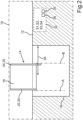
- the Fig.3 shows the flexible display surface element 16 in its pre-tension or reset, and the course of the second adjustment direction 28.
- This can, as in the Fig.1 and in the Fig.2 illustrated, preferably run perpendicular to the first adjustment direction 22, i.e. along the width of a motor vehicle.
- the arrangement of the clamping element 20 and the deflection element 24 can also be mirrored, i.e. for example the clamping element 20 can be arranged on the passenger side of the display surface element 16 and the deflection element 24 can be arranged on the driver side thereof.
- the clamping element 20 and the deflection element 24 can be part of an adjustment device 30.
- the adjustment device 30 can preferably have two linear drives in which a height is set by moving the clamping element 20 and a width by moving the deflection element 24.
- the movement of the clamping element 20 and thus the adjustment of the height is shown.
- the deflection element 24 can also be pushed upwards when the clamping element 20 is moved.
- the Fig.2 shows the display device 14 at a time when the display surface element 16 has already been extended further.
- An optional control device 32 for example a control unit of the motor vehicle 10 or a control chip of the display device 14, can control the adjustment device 30.
- a data communication connection 34 is shown schematically, which can be a wireless data communication connection, for example a WLAN connection, or for example a data bus of the motor vehicle 10.
- the data communication connection 34 is shown schematically only to the deflection element 24, but can be For example, it can be connected to a central chip of the adjustment device 30, which can then control the linear kinematics of the clamping element 20 and the deflection element 24.
- the adjustment device 30 can have an electric motor, for example.
- the optional control device 32 can have a processor device 35, for example, and/or a data memory 36, on which, for example, a program code for carrying out the method according to the invention can be stored.
- the control device 32 can receive and evaluate a corresponding signal from, for example, a driver assistance system of the motor vehicle 10 (method step S1) and, for example, when a piloted driving mode is determined (S2), generate a control signal for operating the kinematics (S3).
- the control device 32 can then transmit the generated control signal to the adjustment device 30 (S4).
- the initial position can then be set again, in which the display surface element 16 can be used, for example, to display driving data, such as a speed, a speedometer reading and a tank level (see. Fig.1 ).
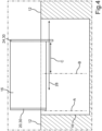
- the Fig.4 shows a view into the cockpit, with the display surface element 16 already in the panoramic position.
- the Fig.4 shows the kinematics when the display surface element 16 is widened in the direction of a Y-axis, i.e. along a motor vehicle transverse axis or the second adjustment direction 28, in the panoramic position, which can also be referred to as the clamping position.
- the control device 32 is in the Fig.4 not shown, but can be designed as in the Fig.1 and in the Fig.2 shown.
- Double arrow C shows the widening compared to the initial position (clamping position).
- the display surface element 16 can, for example, have a width ratio of 16:9. By combining the height and By adjusting the width, this format can also be retained in the initial position. In other words, the visible area of the display surface element 16 can be dynamically enlarged and reduced.
- the Fig.5 illustrates by the top view that the left side of the display surface element 16 remains firmly on the clamping element 20 when clamped, and when, for example, the deflection element 24 of the display surface element 16 is moved in a roller-like manner, it is clamped and the return element 26 is pulled elongated.
- the display surface element 16 is therefore under higher tension and, when the deflection element 24 is moved back towards the clamping element 20, it is pulled towards the clamping element 20 by the return element 26.
- a display surface element 16 for example a display
- a display surface element 16 which can be enlarged and/or reduced as desired in both height and width.
- an extension kinematics is used for the increase in height and a flexible display with corresponding kinematics and retraction for the widening.
- the flexible exemplary display is, for example, firmly clamped on one side and the other side of the display can be hung and tensioned on the same clamping element 20, for example a clamping part, by means of, for example, a spring as a return element 26.
- a simple deflection roller as a deflection element 24, a return element 26, for example a return unit, and the flexibility of the exemplary display are used.
- the system can be extended and retracted continuously up to the maximum size, as well as widened and any format can be freely adjusted.
- Another advantage is that different display sizes can be shown.
- the kinematics used are simple.
Landscapes
- Engineering & Computer Science (AREA)
- Mechanical Engineering (AREA)
- Chemical & Material Sciences (AREA)
- Combustion & Propulsion (AREA)
- Transportation (AREA)
- Instrument Panels (AREA)
- Fittings On The Vehicle Exterior For Carrying Loads, And Devices For Holding Or Mounting Articles (AREA)
- Devices For Indicating Variable Information By Combining Individual Elements (AREA)
Description
- Die Erfindung betrifft eine Anzeigevorrichtung, also ein Gerät, eine Gerätekomponente oder eine Gerätegruppe, das/die zum Anzeigen von Anzeigeinhalten ausgestaltet ist. Die Anzeigevorrichtung umfasst ein flexibles Anzeigeflächenelement mit einer Anzeigefläche zum Anzeigen des Anzeigeinhalts. Die Erfindung betrifft auch ein Kraftfahrzeug mit einer solchen Anzeigevorrichtung.
- Displays finden immer mehr Einzug in Fahrzeuge und werden zu designerischen Elementen. Es besteht der Wunsch, möglichst große Displays darzustellen und diese in der Größe abhängig von einem Anwendungsfall, zum Beispiel bei einer manuellen oder pilotierten Fahrt, variieren zu können. Weiterhin gibt es den Wunsch, Displays in einer attraktiven Art zu inszenieren.
- Vor allem der Bauraum, aber auch zum Beispiel Gesetze, beschränken die mögliche Größe und Position festverbauter, starrer Displays.
- Die
DE 101 15 050 A1 beschreibt eine Anzeigevorrichtung, insbesondere für Fahrzeuge, die einen flachen Bildschirm sowie Positionierungsmittel umfasst, mit welchen der flache Bildschirm in eine gewünschte Betrachtungsposition bewegbar ist. - Die
DE 41 28 663 A1 beschreibt eine Armaturentafel, die zur Anzeige von Informationen einen Bildschirm und zum Abrufen dieser Informationen sowie zur Eingabe von Daten ein Tastenfeld aufweist. - Aus der
EP 1 637 387 A1 ist eine Anzeigevorrichtung für ein Fahrzeug bekannt, die ein Display zur Darstellung von Daten von Applikationen für einen Fahrzeugnutzer umfasst, und Schwenkmittel zum Verrücken des Displays zwischen wenigstens zwei Positionen. - Aus der
DE 10 2016 221 254 B3 ist eine Verstellvorrichtung für ein aufrollbares Display bekannt. - Die
US 2018/0260001 A1 beschreibt ein biegsames Display, dass in einem Kraftfahrzeug zum Anzeigen von Anzeigeinhalten verwendet werden kann. Das Display ist derart biegsam, dass es in zwei parallele Ebenen gebogen werden kann und so eine Tiefeninformation des Anzeigeinhaltes darstellen kann. - Die
US 2020/0020255 A1 beschreibt eine Vorrichtung mit einem flexiblen Display, wobei die Vorrichtung das Bereitstellen unterschiedlich großer Anzeigebereiche ermöglicht. - Die
WO 2019/107909 A1 beschreibt ein ein- und ausziehbares Display. - Die
WO 2009/095992 A1 beschreibt ebenfalls ein größenverstellbares Display, das mittels seitlich angeordneter Arme aufgespannt werden kann, um eine vergrößerte Anzeigefläche bereitzustellen. - Die Höhe der Anzeigeflächen der Anzeigegeräte aus dem Stand der Technik wird durch Ausfahren oder Abrollen der Anzeigeflächen verändert.
- Eine der Erfindung zugrunde liegende Aufgabe ist das Erhöhen einer Dynam ik bei der Größenänderung einer Anzeigefläche.
- Die Erfindung basiert auf der Idee, ein Anzeigeflächenelement, also zum Beispiel ein Display, nicht nur in einer Richtung auszufahren und damit nur dessen Höhe zu vergrößern, sondern die Anzeigefläche auch in einer zweiten Richtung, nämlich in der Breite, zu vergrößern. Dafür kommt ein flexibles Anzeigeflächenelement zum Einsatz, zum Beispiel ein flexibles Display wie zum Beispiel ein flexibler OLED-Bildschirm. Die Flexibilität des Displays wird dabei für die Verbreiterung des Displays genutzt. Eine erste Kinematik fährt das Anzeigeflächenelement, zum Beispiel die gesamte Displayeinheit, aus und stellt somit die Anzeigehöhe ein. Das Anzeigeflächenelement ist in einer Ausgangslage, also in der Lage, in der eine kleinere Anzeigefläche zur Verfügung steht wie in einer Panoramalage, nicht aufgerollt, sondern mittels einer zweiten Kinematik und einem Rückstellelement, zum Beispiel einer Feder, ein- oder aufgespannt.
- Damit kann die Anzeigebreite eingestellt werden. Die gesamte Einheit bietet die Möglichkeit, die Anzeigeflächengröße und den Formfaktor frei zwischen einer minimalen und einer maximalen Größe einzustellen. Vorteilhaft ergibt sich, dass mit einer einfachen Kinematik verschiedene Größen einer Anzeigefläche dargestellt - also eingestellt - werden können. Bei Implementierung dieses Prinzips wird weniger Bauraum benötigt.
- Die erfindungsgemäße Anzeigevorrichtung, vorzugsweise eine Anzeigevorrichtung für ein Kraftfahrzeug, umfasst ein flexibles Anzeigeflächenelement mit einer Anzeigefläche zum Anzeigen eines Anzeigeinhalts. Unter einem flexiblen Anzeigeflächenelement wird ein Bauteil, das als Anzeigefläche ausgestaltet ist, verstanden, welches nicht starr ist, sondern beweglich, also biegsam und/oder elastisch und/oder rollbar und/oder aufspannbar. Das Anzeigeflächenelement kann vorzugsweise als Bildschirm ausgestaltet sein, zum Beispiel als Bildschirm mit organischen Leuchtdioden ("organic light emitting diodes", "OLEDs").
- Die Anzeigevorrichtung umfasst eine Verstelleinrichtung, die aufweist oder umfasst: ein in eine erste Verstellrichtung beweglich angeordnetes, als Stab ausgestaltetes Einspannelement, ein am Einspannelement angeordnetes Rückstellelement, und ein als Stab ausgestaltete Umlenkelement. Vorzugsweise kann das Einspannelement nur in die erste Verstellrichtung beweglich angeordnet sein.
- Unter einer Verstelleinrichtung wird eine mechanische und/oder elektrische Bauteilgruppe verstanden, die gerichtet Bewegungen ausführen kann, und die auch als Kinematik bezeichnet werden kann. Die Verstelleinrichtung kann zum Bewegen des Einspannelements und das Umlenkelement zum Beispiel einen Seilzug, einen Bowden-Zug, eine Hydraulik, eine Führungsschiene und/oder einen Elektromotor aufweisen.
- Unter einem Einspannelement wird ein Bauteil verstanden, das das Anzeigeflächenelement festhält, in das das Anzeigeflächenelement also zum Beispiel eingeklemmt oder eingespannt oder aufgeklebt werden kann; und das dazu beiträgt, dass das Anzeigeflächenelement straff gelagert wird. Das Einspannelement kann in die erste Verstellrichtung zum Beispiel verschoben oder gezogen werden.
- Ein Rückstellelement ist ein Bauteil oder eine Bauteilgruppe, das/die dazu ausgestaltet ist, eine Rückstellkraft auf das Anzeigeflächenelement auszuüben, kann also zum Beispiel eine Feder, ein Faltenbalg oder ein Gummizug sein oder umfassen.
- Eine erste Seitenkante des Anzeigeflächenelements ist an der Länge des Einspannelements angeordnet oder gelagert, vorzugsweise befestigt. Vorzugsweise kann die erste Seitenkante entlang der Länge des Einspannelements angeordnet sein. Eine der ersten Seitenkante gegenüberliegende zweite Seitenkante des Anzeigeflächenelements ist über das Rückstellelement mit dem Einspannelement verbunden, sodass eine Fläche des Anzeigeflächenelements gebogen ist und einen Beugungsbereich bildet. Der Beugungsbereich ist derjenige Bereich, in dem das flächige Anzeigeflächenelement umgelegt, also gebogen ist. Der Beugungsbereich wird also durch das gebogene oder faltenlos umgelegte Anzeigeflächenelement gebildet, ist also der Bereich, wo die Fläche des Anzeigeflächenelements eine Kurve bildet. Vorzugsweise ist das Anzeigeflächenelement nur einmal faltenlos umgebogen, also nicht gerollt.
- Eine Länge des Umlenkelements erstreckt sich im Wesentlichen in die gleiche Richtung wie das Einspannelement, vorzugsweise in die gleiche Richtung. Seine Länge hat also die gleiche Orientierung wie das Einspannelement. Das Umlenkelement erstreckt sich innerhalb der Beugung oder "Innenkurve" des gebogenen Anzeigeflächenelements und in ist eine zweite Verstellrichtung beweglich angeordnet, sodass die Verstelleinrichtung dazu ausgelegt ist, einen Abstand zwischen dem Umlenkelement und dem Einspannelement zu ändern. Vorzugsweise verläuft die zweite Verstellrichtung senkrecht zu der ersten Verstelleinrichtung. Das Umlenkelement kann in die zweite Verstellrichtung zum Beispiel verschoben oder gezogen werden.
- Das Rückstellelement übt eine Rückstellkraft auf das Anzeigeflächenelement zum Einspannelement hin aus. In der Ausgangslage, in der das Einspannelement und das Umlenkelement in einem geringeren Abstand zueinander stehen als in einer Panoramalage, ist das Anzeigeflächenelement durch das Rückstellelement ebenso gespannt wie in der Panoramalage. In beiden Lagen ist also ein Anzeigeinhalt des Anzeigeflächenelements gut sichtbar, da das Anzeigeflächenelement in beiden Lagen gespannt ist. In der Panoramalage ist die für zum Beispiel einen Insassen eines Kraftfahrzeugs sichtbare Breite jedoch größer, vorzugsweise auch die Höhe.
- Es ergeben sich die oben genannten Vorteile. Das Anzeigeflächenelement wird nicht oder kaum geknickt oder gefaltet, wodurch das Material geschont wird und keine Falten bei der Anzeige der Anzeigeinhalte stören. Die für die Anzeige von Anzeigeinhalten verfügbare Fläche kann in ihrer Größe stufenlos verstellt werden.
- Vorzugsweise kann die zweite Verstellrichtung senkrecht zu der ersten Verstellrichtung und/oder senkrecht zu der Erstreckung der Länge des Umlenkelements verlaufen. Neben einer Höhe kann so eine Breite der Anzeigefläche und damit ein Panoramaformat eingestellt werden. Ein solches Format ist insbesondere im Kraftfahrzeug sinnvoll, da der Platz über zum Beispiel der Schalttafel begrenzt ist, und da ein Panoramaformat für zum Beispiel Filme sehr nützlich ist.
- Das flexible Anzeigeflächenelement kann nur einmal faltenlos um das Umlenkelement gebogen sein. Das Anzeigeflächenelement ist dadurch aufspannbar. Im Gegensatz zu einem aufgerollten Anzeigeflächenelement ergibt sich, dass kein Antrieb zum Auf- und Abrollen des Anzeigeflächenelements notwendig ist, dass kein Schmutz auf dem Anzeigeflächenelement mit eingerollt wird und dadurch an andere Stellen des Anzeigeflächenelements kommt, und eine Wahrscheinlichkeit, dass beim Wechsel zwischen Ausgangslage und Panoramalage Knicke entstehen, ist deutlich reduziert.
- Idealerweise kann die Anzeigevorrichtung eine Steuereinrichtung umfassen, die dazu ausgelegt ist, in Abhängigkeit von einem eingestellten Gebrauchsmodus, zum Beispiel einem Gebrauchsmodus der Anzeigevorrichtung, ein Steuersignal zu erzeugen, das ein Verstellen des Einspannelements in die erste Verstellrichtung und ein Verstellen des Umlenkelements in die zweite Verstellrichtung beschreibt. Vorzugsweise kann das erzeugte Steuersignal ein gleichzeitiges Verstellen von Einspannelement und Umlenkelement beschreiben. So können Ausgangslage und Panoramalage von Anwendungsfall zu Anwendungsfall bereitgestellt werden.
- Unter einer Steuereinrichtung wird ein Gerät, eine Gerätegruppe oder eine Gerätekomponente verstanden, das/die zum Empfangen und Auswerten von Signalen ausgestaltet und eingerichtet ist, sowie zum Erzeugen von Steuersignalen. Die Steuereinrichtung kann zum Beispiel als Steuerchip oder Steuergerät ausgestaltet sein.
- Das erzeugte Steuersignal kann einen Wechsel zwischen einer Ausgangslage des Anzeigeflächenelements und einer Panoramalage, in der ein Abstand zwischen dem Umlenkelement und dem Einspannelement das Anzeigeflächenelement größer ist als in der Ausgangslage, beschreiben. Vorzugsweise kann der eingestellte Gebrauchsmodus, also ein aktueller oder ein von einem Benutzer ausgewählter Gebrauchsmodus, ein Fahrmodus eines Kraftfahrzeugs sein.
- Die oben gestellte Aufgabe wird gelöst durch ein Kraftfahrzeug, das eine Ausführungsform der erfindungsgemäßen Anzeigevorrichtung umfasst. Es ergeben sich die oben beschriebenen Vorteile. Das erfindungsgemäße Kraftfahrzeug ist bevorzugt als Kraftwagen, insbesondere als Personenkraftwagen oder Lastkraftwagen, oder als Personenbus oder Motorrad ausgestaltet.
- Vorzugsweise können Anzeigeflächenelement und Verstelleinrichtung in der Ausgangslage zumindest teilweise in einem Schacht eines Innenraumverkleidungselements angeordnet sein, also zumindest teilweise in dem Schacht versenkt sein. Das Einspannelement und das Umlenkelement können sich jeweils vertikal oder im Wesentlichen vertikal erstrecken, also im Wesentlichen entlang einer Kraftfahrzeug-Hochachse verlaufen. Bei einem Wechsel zwischen der Ausgangslage und einer Panoramalage kann die Steuereinrichtung die Verstelleinrichtung dazu veranlassen, das Einspannelement vertikal und das Umlenkelement horizontal zu bewegen.
- Unter einem Innenraumverkleidungselement wird dabei ein Element der Innenraumverkleidung des Kraftfahrzeugs verstanden. Das Innenraumverkleidungselement kann vorzugsweise eine Schalttafel, eine Hutze oder ein Armaturenbrett des Kraftfahrzeugs sein.
- Die oben gestellte Aufgabe wird, unter Erreichen der bereits genannten Vorteile, gelöst durch ein Verfahren zum Betreiben einer Ausführungsform der erfindungsgemäßen Anzeigevorrichtung, vorzugsweise einer Anzeigevorrichtung einer Ausführungsform des erfindungsgemäßen Kraftfahrzeugs, wobei die Steuereinrichtung:
- einen eingestellten Gebrauchsmodus feststellt, vorzugsweise einen eingestellten Gebrauchsmodus des Kraftfahrzeugs, insbesondere einen aktuellen oder vom Benutzer ausgewählten Fahrmodus; und
- in Abhängigkeit von einem eingestellten Gebrauchsmodus ein Steuersignal erzeugt, das ein Verstellen des Einspannelements in die erste Verstellrichtung und ein Verstellen des Umlenkelements in die zweite Verstellrichtung beschreibt; vorzugsweise ein gleichzeitiges Verstellen von Einspannelement und Umlenkelement.
- In einer Ausführungsform des erfindungsgemäßen Verfahrens kann die Anzeigevorrichtung eine Anzeigevorrichtung eines Kraftfahrzeugs sein, wobei der eingestellte Gebrauchsmodus ein eingestellter Fahrmodus ist; vorzugsweise wobei die Steuereinrichtung in einem pilotierten Fahrmodus die Panoramalage des Anzeigeflächenelements einstellt. Je nach Fahrmodus kann die Anzeigefläche bedarfsgerecht eingestellt werden. Bei einer pilotierten Fahrt, bei der die Anzeigevorrichtung auch einen hohen Stellenwert im Entertainment einnimmt, kann so eine besonders große Fläche für zum Beispiel einen Film bereitgestellt werden. Bei einer manuellen oder teilweise automatisierten Fahrt kann eine kleinere Anzeigefläche eingestellt werden, auf der dann zum Beispiel die wichtigen Fahrtdaten angezeigt werden können und möglichst viel Sicht durch die Windschutzscheibe ermöglicht wird.
- Zu der Erfindung gehört auch die Steuervorrichtung für das Kraftfahrzeug, die zum Durchführen des erfindungsgemäßen Verfahrens eingerichtet ist. Die Steuereinrichtung kann zum Beispiel als Steuerchip oder Steuergerät ausgestaltet sein. Die Steuervorrichtung weist eine Prozessoreinrichtung auf, die dazu eingerichtet ist, eine Ausführungsform des erfindungsgemäßen Verfahrens durchzuführen. Die Prozessoreinrichtung kann hierzu zumindest einen Mikroprozessor und/oder zumindest einen Mikrocontroller und/oder zumindest einen FPGA (Field Programmable Gate Array) und/oder zumindest einen DSP (Digital Signal Processor) aufweisen. Des Weiteren kann die Prozessoreinrichtung Programmcode aufweisen, der dazu eingerichtet ist, bei Ausführen durch die Prozessoreinrichtung die Ausführungsform des erfindungsgemäßen Verfahrens durchzuführen. Der Programmcode kann in einem Datenspeicher der Prozessoreinrichtung gespeichert sein.
- Zu der Erfindung gehören auch Weiterbildungen des erfindungsgemäßen Kraftfahrzeugs, des erfindungsgemäßen Verfahrens, und der erfindungsgemäßen Steuereinrichtung, die Merkmale aufweisen, wie sie bereits im Zusammenhang mit den Weiterbildungen der erfindungsgemäßen Anzeigevorrichtung beschrieben worden sind. Aus diesem Grund sind die entsprechenden Weiterbildungen des erfindungsgemäßen Kraftfahrzeugs, des erfindungsgemäßen Verfahrens, und der erfindungsgemäßen Steuereinrichtung hier nicht noch einmal beschrieben.
- Die Erfindung umfasst auch die Kombinationen der Merkmale der beschriebenen Ausführungsformen.
- Im Folgenden sind Ausführungsbeispiele der Erfindung beschrieben. Hierzu zeigt:
- Fig. 1
- eine schematische Darstellung zu einem Ausführungsbeispiel der erfindungsgemäßen Vorrichtungen und dem erfindungsgemäßen Verfahren, wobei das Anzeigeflächenelement in der Ausgangslage ist;
- Fig. 2
- eine weitere schematische Darstellung zu dem Ausführungsbeispiel, mit dem Anzeigeflächenelement in der Ausgangslage;
- Fig. 3
- eine schematische Darstellung zu dem Ausführungsbeispiel in einer Aufsicht mit dem Anzeigeflächenelement in der Ausgangslage;
- Fig. 4
- eine weitere schematische Darstellung zu dem Ausführungsbeispiel, mit dem Anzeigeflächenelement in der Panoramalage; und
- Fig. 5
- eine weitere schematische Darstellung zu dem Ausführungsbeispiel in einer Aufsicht mit dem Anzeigeflächenelement in der Panoramalage.
- Bei den im Folgenden erläuterten Ausführungsbeispielen handelt es sich um bevorzugte Ausführungsformen der Erfindung. Bei den Ausführungsbeispielen stellen die beschriebenen Komponenten der Ausführungsformen jeweils einzelne, unabhängig voneinander zu betrachtende Merkmale der Erfindung dar, welche die Erfindung jeweils auch unabhängig voneinander weiterbilden. Daher soll die Offenbarung auch andere als die dargestellten Kombinationen der Merkmale der Ausführungsformen umfassen. Des Weiteren sind die beschriebenen Ausführungsformen auch durch weitere der bereits beschriebenen Merkmale der Erfindung ergänzbar.
- In den Figuren bezeichnen gleiche Bezugszeichen jeweils funktionsgleiche Elemente.
- Die
Fig. 1 veranschaulicht schematisch das Prinzip der erfindungsgemäßen Vorrichtungen und des erfindungsgemäßen Verfahrens anhand eines ersten Ausführungsbeispiels. Hierzu zeigt dieFig. 1 schematisch einen Bilck in ein Cockpit eines Kraftfahrzeugs 10, zum Beispiel eines Buses oder eines Personenkraftwagens. - In einer Aufsicht zeigt die
Fig. 1 schematisch ein Innenraumverkleidungselement 12, das insbesondere ein Armaturenbrett oder eine Schalttafel sein kann, alternativ zum Beispiel eine Mittelkonsole oder Armlehne. Die in derFig. 1 gezeigte Anzeigevorrichtung 14 ist dabei beispielhaft in einer Ruhelage gezeigt, in der das Anzeigeflächenelement 16 zumindest teilweise in einem Schacht 18 des Innenraumverkleidungselements 12 eingefahren sein kann, wobei zum Beispiel das obere Viertel oder das obere Drittel des Anzeigeflächenelements 16 herausragen und damit sichtbar sein kann. Wird die Anzeigevorrichtung 14 nicht gebraucht, so kann das Anzeigeflächenelement 16 zum Beispiel vollständig im Schacht 18 versenkt sein. - In einer Variante kann das Anzeigeflächenelement 16 in der Ausgangslage oder Einspannlage auf die Breite des Schachts 18 eingestellt sein. Zum Ausbreiten in der horizontalen, zweiten Verstellrichtung 28 kann dann zum Beispiel zunächst das Anzeigeflächenelement 16 komplett aus dem Schacht 18 herausgefahren werden, und danach kann das Umlenkelement 24 entlang der Kraftfahrzeugquerachse, also in die zweite Verstellrichtung 28, verstellt werden. Alternativ, wie hier in den Figuren gezeigt, kann der Schacht so breit sein, dass das Anzeigeflächenelement 16 in Bezug auf die Breite auch in der Panoramalage hineinpasst. Die Linien A und B heben dabei die Breite des Anzeigeflächenelements 16 in der Einspannlage hervor.
- In der Ausgangslage, die auch als Einspannlage bezeichnet werden kann, kann eine von dem Benutzer sichtbare Breite auf die Breite des Schachts eingestellt oder geringer sein.
- Das Anzeigeflächenelement 16 kann zum Beispiel ein Bildschirm mit organischen Leuchtdioden (OLEDs) sein. Geeignete, biegsame Displays sind dem Fachmann aus dem Stand der Technik bekannt. In der Aufsicht der
Fig. 1 kann das Anzeigeflächenelement zum Beispiel fahrerseitig mit einem Einspannelement 20 verbunden sein, zum Beispiel auf dieses aufgeklebt, eingespannt oder eingeklemmt sein, wobei das Einspannelement 20 als Stab ausgestaltet und zum Beispiel über eine Führungsschiene (in derFig. 1 nicht gezeigt) in die erste Verstellrichtung 22 bewegt werden kann, also entlang der Kraftfahrzeug-Hochachse. Hierzu kann das Einspannelement 20 zum Beispiel eine Klemme, ein Festlager, oder einen Mechanismus zum Einspannen des Anzeigeflächenelements 16 aufweisen. An dem Einspannelement 20 wird das Anzeigeflächenelement 16 festgehalten. - Das Anzeigeflächenelement 16 ist im Beispiel der
Fig. 1 einmal um ein stabförmiges Umlenkelement 24 gebogen oder gewickelt, vorzugsweise nur einmal faltenlos um das Umlenkelement 24 gelegt. Das Umlenkelement 24 kann zum Beispiel ein Stab aus Metall oder Kunststoff sein, der vorzugsweise als Rolle mit zum Beispiel einem Radius von zehn Millimetern ausgestaltet sein kann. Die der am Einspannelement 20 festgehaltenen Seitenkante gegenüberliegende Seitenkante des Anzeigeflächenelements 16 ist mit dem Einspannelement 20 über ein Rückstellelement 26 verbunden. Aufgrund der besseren Übersichtlichkeit derFig. 1 ist das Rückstellelement 26 in derFig. 1 (sowie in derFig. 2 , undFig. 4 ) nicht gezeigt. - Zur Veranschaulichung der Anordnung der gegenüberliegenden Seitenkante am Einspannelement 20 zeigt die
Fig. 3 eine Aufsicht, in der das Rückstellelement 26 zum Beispiel als Feder, Gummizug oder Faltenbalg ausgestaltet sein kann. Das Rückstellelement ist also ein nachgiebiges Element zum Spannen des Anzeigeflächenelements 16, das das Anzeigeflächenelement 16 unter Spannung hält. Das Rückstellelement 26 kann deswegen auch als "Federelement" bezeichnet werden. - Die
Fig. 3 zeigt das flexible Anzeigeflächenelement 16 in seiner Vorspannung beziehungsweise Rückstellung, und den Verlauf der zweiten Verstellrichtung 28. Diese kann, wie in derFig. 1 und in derFig. 2 verdeutlicht, vorzugsweise senkrecht zu der ersten Verstellrichtung 22 verlaufen, also entlang einer Kraftfahrzeugbreite. In einer Variation der in den Figuren dargestellten Anzeigevorrichtung 14 kann die Anordnung des Einspannelements 20 und des Umlenkelements 24 auch gespiegelt sein, also zum Beispiel das Einspannelement 20 beifahrerseitig vom Anzeigeflächenelement 16 und das Umlenkelement 24 fahrerseitig davon angeordnet sein. - Das Einspannelement 20 und das Umlenkelement 24 können Bestandteil einer Verstelleinrichtung 30 sein. Zusammenfassend kann die Verstelleinrichtung 30 vorzugsweise zwei Linearantriebe aufweisen, in der mittels des Bewegens des Einspannelements 20 eine Höhe eingestellt wird, und durch Bewegen des Umlenkelements 24 ein Breite. In der
Fig. 1 und in derFig. 2 ist zunächst das Verfahren des Einspannelements 20 und damit das Einstellen der Höhe gezeigt. Optional kann beim Verfahren des Einspannelements 20 auch das Umlenkelement 24 mit nach oben geschoben werden. - Die
Fig. 2 zeigt die Anzeigevorrichtung 14 zu einem Zeitpunkt, wo das Anzeigeflächenelement 16 schon weiter ausgefahren ist. Eine optionale Steuereinrichtung 32, zum Beispiel ein Steuergerät des Kraftfahrzeugs 10 oder ein Steuerchip der Anzeigevorrichtung 14, kann die Verstelleinrichtung 30 steuern. Hierzu ist schematisch eine Datenkommunikationsverbindung 34 gezeigt, die zum Beispiel eine drahtlose Datenkommunikationsverbindung sein kann, zum Beispiel eine WLAN-Verbindung, oder zum Beispiel ein Datenbus des Kraftfahrzeugs 10. Dabei ist die Datenkommunikationsverbindung 34 schematisch nur zum Umlenkelement 24 gezeigt, kann jedoch zum Beispiel mit einem zentralen Chip der Verstelleinrichtung 30 verbunden sein, der dann die Linearkinematik von Einspannelement 20 und Umlenkelement 24 steuern kann. Hierzu kann die Verstelleinrichtung 30 zum Beispiel einen Elektromotor aufweisen. Die optionale Steuereinrichtung 32 kann zum Beispiel eine Prozessoreinrichtung 35 aufweisen, und/oder einen Datenspeicher 36, auf dem zum Beispiel ein Programmcode zum Durchführen des erfindungsgemäßen Verfahrens abgespeichert sein kann. - Erfolgt die Einstellung des Anzeigeflächenelements 16 in Abhängigkeit von einem aktuellen Fahrmodus des Kraftfahrzeugs 10, so kann die Steuereinrichtung 32 ein entsprechendes Signal aus zum Beispiel einem Fahrerassistenzsystem des Kraftfahrzeugs 10 empfangen (Verfahrensschritt S1) und auswerten, und zum Beispiel beim Feststellen eines pilotierten Fahrmodus (S2) ein Steuersignal zum Betreiben der Kinematik erzeugen (S3). Das erzeugte Steuersignal kann die Steuereinrichtung 32 dann an die Verstelleinrichtung 30 übertragen (S4). In einem manuellen Fahrmodus kann dann zum Beispiel wieder die Ausgangslage eingestellt werden, in der das Anzeigeflächenelement 16 zum Beispiel zum Anzeigen von Fahrdaten, wie zum Beispiel einer Geschwindigkeit, einem Tachometerstand und einem Tankfüllstand, anzeigen kann (vgl.
Fig. 1 ). - Die
Fig. 4 zeigt einen Blick in das Cockpit, wobei sich das Anzeigeflächenelement 16 bereits in der Panoramalage befindet. DieFig. 4 zeigt die Kinematik bei der Verbreiterung des Anzeigeflächenelements 16 in Richtung einer Y-Achse, also entlang einer Kraftfahrzeugquerachse beziehungsweise der zweiten Verstellrichtung 28, in die Panoramalage, die auch als Aufspannlage bezeichnet werden kann. Aus Gründen der besseren Übersichtlichkeit ist die Steuereinrichtung 32 in derFig. 4 nicht gezeigt, kann jedoch in der Ausführung wie in derFig. 1 und in derFig. 2 gezeigt vorhanden sein. Doppelpfeil C zeigt die Verbreiterung im Vergleich zu der Ausgangslage (Einspannlage). - In der Panoramalage kann das Anzeigeflächenelement 16 zum Beispiel ein Breitenverhältnis von 16:9 haben. Durch die Kombination der Höhen- und Breitenverstellung kann dieses Format auch in der Ausgangslage beibehalten werden. Mit anderen Worten kann der sichtbare Bereich des Anzeigeflächenelements 16 dynamisch vergrößert und verkleinert werden.
- Die
Fig. 5 veranschaulicht durch die Aufsicht, dass die linke Seite des Anzeigeflächenelements 16 beim Aufspannen fest am Einspannelement 20 bleibt, und bei zum Beispiel einem walzenartigen Bewegen des Umlenkelements 24 des Anzeigeflächenelements 16 aufgespannt und das Rückstellelement 26 in die Länge gezogen wird. - Das Anzeigeflächenelement 16 steht also unter höherer Spannung und wird, wird das Umlenkelement 24 wieder zum Einspannelement 20 hin verfahren, von dem Rückstellelement 26 zum Einspannelement 20 hin gezogen.
- Insgesamt zeigen die Beispiele, wie durch die Erfindung ein vergrößerbares und/oder verkleinerbares Display bereitgestellt werden kann.
- In einem weiteren Ausführungsbeispiel ist ein Einsatz eines Anzeigeflächenelements 16, zum Beispiel eines Displays, vorgesehen, das sich sowohl in der Höhe als auch in der Breite beliebig vergrößern und/oder verkleinern lässt. Dabei kommt zum Beispiel eine Ausfahrkinematik für die Vergrößerung in der Höhe und ein flexibles Display mit einer entsprechenden Kinematik und Rückstellung für die Verbreiterung zum Einsatz.
- Das flexible beispielhafte Display ist einseitig zum Beispiel fest eingespannt und an demselben Einspannelement 20, zum Beispiel einem Einspannteil, kann mittels zum Beispiel einer Feder als Rückstellelement 26 die andere Seite des Display zum Beispiel eingehangen und gespannt werden.
- Speziell für die Verbreiterung wird zum Beispiel eine einfache Umlenkrolle als Umlenkelement 24, ein Rückstellelement 26, zum Beispiel eine Rückstelleinheit, und die Flexibilität des beispielhaften Displays genutzt.
- Dabei kann das System stufenlos bis zur maximalen Größe ein- und ausgefahren sowie verbreitert und jedes Format frei eingestellt werden.
- Vorteilhaft ergibt sich auch, dass verschiedene Displaygrößen dargestellt werden können. Die eingesetzte Kinematik ist einfach.
Claims (10)
- Anzeigevorrichtung (14), umfassend:- ein flexibles Anzeigeflächenelement (16) mit einer Anzeigefläche zum Anzeigen eines Anzeigeinhalts, und- eine Verstelleinrichtung (30), die ein in eine erste Verstellrichtung (22) beweglich angeordnetes, als Stab ausgestaltetes Einspannelement (20) und ein als Stab ausgestaltetes Umlenkelement (24) umfasst,wobei eine erste Seitenkante des Anzeigeflächenelements (16) an der Länge des Einspannelements (20) angeordnet ist,dadurch gekennzeichnet, dass- die Verstelleinrichtung (30) ein am Einspannelement (20) angeordnetes Rückstellelement (26) umfasst, wobei eine der ersten Seitenkante gegenüberliegende zweite Seitenkante des Anzeigeflächenelements (16) über das Rückstellelement (26) mit dem Einspannelement (20) verbunden ist, sodass eine Fläche des Anzeigeflächenelements (16) gebogen ist und einen Beugungsbereich aufweist, und dass- eine Länge des Umlenkelements (24) sich in die gleiche Richtung wie das Einspannelement (20) erstreckt, das Umlenkelement (24) sich innerhalb der Beugung des gebogenen Anzeigeflächenelements erstreckt und in eine zweite Verstellrichtung (28) beweglich angeordnet ist, um einen Abstand zwischen dem Umlenkelement (24) und dem Einspannelement (20) zu ändern.
- Anzeigevorrichtung (14) nach Anspruch 1, wobei
die zweite Verstellrichtung (28) senkrecht zu der ersten Verstellrichtung (22) und/oder senkrecht zu der Erstreckung der Länge des Umlenkelements (24) verläuft. - Anzeigevorrichtung (14) nach einem der vorhergehenden Ansprüche, wobei das flexible Anzeigeflächenelement (16) nur einmal faltenlos um das Umlenkelement (24) gebogen ist.
- Anzeigevorrichtung (14) nach einem der vorhergehenden Ansprüche, umfassend:- eine Steuereinrichtung (32), die dazu ausgelegt ist, in Abhängigkeit von einem eingestellten Gebrauchsmodus ein Steuersignal zu erzeugen, das ein Verstellen des Einspannelements (20) in die erste Verstellrichtung (22) und ein Verstellen des Umlenkelements (24) in die zweite Verstellrichtung (28) beschreibt, vorzugsweise ein gleichzeitiges Verstellen von Einspannelement (20) und Umlenkelement (24).
- Anzeigevorrichtung (14) nach Anspruch 4, wobei
das erzeugte Steuersignal einen Wechsel zwischen einer Ausgangslage des Anzeigeflächenelements (16) und einer Panoramalage, in der ein Abstand zwischen dem Umlenkelement (24) und dem Einspannelement (20) das Anzeigeflächenelement (16) größer ist als in der Ausgangslage, beschreibt. - Anzeigevorrichtung (14) nach Anspruch 4 oder 5, wobei
der eingestellte Gebrauchsmodus ein Fahrmodus eines Kraftfahrzeugs (10) ist. - Kraftfahrzeug (10), aufweisend eine Anzeigevorrichtung (14) nach einem der vorhergehenden Ansprüche.
- Kraftfahrzeug (10) nach Anspruch 7, wobei das Anzeigeflächenelement (16) und die Verstelleinrichtung (30) in der Ausgangslage zumindest teilweise in einem Schacht (18) eines Innenraumverkleidungselements (12) angeordnet sind, sodass sich das Einspannelement (20) und das Umlenkelement (24) jeweils vertikal erstrecken; und wobei bei einem Wechsel zwischen der Ausgangslage und einer Panoramalage die Steuereinrichtung (32) die Verstelleinrichtung (30) dazu veranlasst, das Einspannelement (20) vertikal und das Umlenkelement (24) horizontal zu bewegen.
- Verfahren zum Betreiben einer Anzeigevorrichtung (14) nach einem der Ansprüche 1 bis 6, wobei die Steuereinrichtung (32):- einen eingestellten Gebrauchsmodus feststellt (S2), und- in Abhängigkeit von einem eingestellten Gebrauchsmodus ein Steuersignal erzeugt (S3), das ein Verstellen des Einspannelements (20) in die erste Verstellrichtung (22) und ein Verstellen des Umlenkelements (24) in die zweite Verstellrichtung (28) beschreibt; vorzugsweise ein gleichzeitiges Verstellen von Einspannelement (20) und Umlenkelement (24).
- Verfahren nach Anspruch 9, zum Betreiben einer Anzeigevorrichtung (14) eines Kraftfahrzeugs (10) nach einem der Ansprüche 7 oder 8, und wobei der eingestellte Gebrauchsmodus ein eingestellter Fahrmodus ist; vorzugsweise wobei die Steuereinrichtung (32) in einem pilotierten Fahrmodus die Panoramalage des Anzeigeflächenelements (16) einstellt.
Applications Claiming Priority (2)
| Application Number | Priority Date | Filing Date | Title |
|---|---|---|---|
| DE102020101877.0A DE102020101877B3 (de) | 2020-01-27 | 2020-01-27 | Anzeigevorrichtung, Kraftfahrzeug mit einer Anzeigevorrichtung, und Verfahren zum Betreiben einer Anzeigevorrichtung |
| PCT/EP2020/087419 WO2021151593A1 (de) | 2020-01-27 | 2020-12-21 | Anzeigevorrichtung, kraftfahrzeug mit einer anzeigevorrichtung, und verfahren zum betreiben einer anzeigevorrichtung |
Publications (2)
| Publication Number | Publication Date |
|---|---|
| EP4096956A1 EP4096956A1 (de) | 2022-12-07 |
| EP4096956B1 true EP4096956B1 (de) | 2024-06-12 |
Family
ID=74141545
Family Applications (1)
| Application Number | Title | Priority Date | Filing Date |
|---|---|---|---|
| EP20838509.6A Active EP4096956B1 (de) | 2020-01-27 | 2020-12-21 | Anzeigevorrichtung, kraftfahrzeug mit einer anzeigevorrichtung, und verfahren zum betreiben einer anzeigevorrichtung |
Country Status (5)
| Country | Link |
|---|---|
| US (1) | US12083886B2 (de) |
| EP (1) | EP4096956B1 (de) |
| CN (1) | CN115003538B (de) |
| DE (1) | DE102020101877B3 (de) |
| WO (1) | WO2021151593A1 (de) |
Families Citing this family (2)
| Publication number | Priority date | Publication date | Assignee | Title |
|---|---|---|---|---|
| DE102021120856B3 (de) | 2021-08-11 | 2022-08-18 | Audi Aktiengesellschaft | Verfahren zum Betreiben einer Anzeigevorrichtung eines Kraftfahrzeugs, Kraftfahrzeug, und Steuereinrichtung |
| DE102021128254A1 (de) | 2021-10-29 | 2023-05-04 | Bayerische Motoren Werke Aktiengesellschaft | Anzeigevorrichtung für ein Fahrzeug |
Family Cites Families (26)
| Publication number | Priority date | Publication date | Assignee | Title |
|---|---|---|---|---|
| DE4128663C2 (de) * | 1991-06-13 | 2002-10-02 | Siemens Ag | Armaturentafel für ein Kraftfahrzeug |
| DE10115050B4 (de) * | 2001-03-27 | 2006-04-13 | Robert Bosch Gmbh | Anzeigevorrichtung, insbesondere für ein Fortbewegungsmittel |
| DE102004016641A1 (de) * | 2004-03-30 | 2005-11-03 | Recaro Aircraft Seating Gmbh & Co. Kg | Fahrzeugsitz, insbesondere Fluggastsitz |
| EP1637387B1 (de) * | 2004-09-16 | 2009-06-03 | Daimler AG | Anzeigevorrichtung für ein Fahrzeug |
| DE102005038485A1 (de) * | 2005-08-13 | 2007-02-15 | Fischer Automotive Systems Gmbh | Versenkbarer Anzeigebildschirm für ein Kraftfahrzeug |
| JP4779046B2 (ja) * | 2008-01-29 | 2011-09-21 | パイオニア株式会社 | 電子機器 |
| KR102014791B1 (ko) * | 2012-03-27 | 2019-10-21 | 엘지전자 주식회사 | 플렉서블 디스플레이 스크린의 확장된 길이에 기초한 어플리케이션 실행 최적화 방법 |
| KR101661526B1 (ko) * | 2012-04-08 | 2016-10-04 | 삼성전자주식회사 | 플렉서블 디스플레이 장치 및 그 ui 방법 |
| KR102047692B1 (ko) * | 2013-02-05 | 2019-11-22 | 엘지전자 주식회사 | 플렉서블 디스플레이를 탑재한 디바이스 및 그의 제어 방법 |
| US9424790B2 (en) * | 2013-04-18 | 2016-08-23 | Lg Electronics Inc. | Portable device and control method for the same |
| KR102139530B1 (ko) * | 2013-04-18 | 2020-07-30 | 엘지전자 주식회사 | 포터블 디바이스 및 그 제어 방법 |
| US10086762B2 (en) * | 2014-12-10 | 2018-10-02 | Lg Electronics Inc. | Vehicle display device and vehicle comprising same |
| US20160266782A1 (en) * | 2015-03-11 | 2016-09-15 | Atieva, Inc. | Positionable User Interface for Vehicular Use |
| KR102359550B1 (ko) * | 2015-08-26 | 2022-02-08 | 엘지전자 주식회사 | 플렉서블 디스플레이 장치 및 그의 동작 방법 |
| DE102015011403A1 (de) * | 2015-08-29 | 2017-03-16 | Audi Ag | Biegbare Anzeige zur Darstellung von Tiefeninformationen |
| KR102351959B1 (ko) * | 2015-12-17 | 2022-01-17 | 삼성디스플레이 주식회사 | 표시 장치 및 그 제어 방법 |
| DE102016211320B4 (de) * | 2016-06-24 | 2023-10-05 | Bayerische Motoren Werke Aktiengesellschaft | Anzeigevorrichtung für ein Projektionsanzeigesystem, insbesondere zum Einsatz in einem Fahrzeug, sowie Anzeigesystem |
| DE102016221254B3 (de) * | 2016-10-28 | 2018-04-05 | Audi Ag | Verstellvorrichtung für ein aufrollbares Display |
| KR102389189B1 (ko) | 2017-11-29 | 2022-04-22 | 삼성전자주식회사 | 확장가능한 디스플레이 영역을 갖는 플렉시블 디스플레이를 구비한 전자 장치 |
| KR102088215B1 (ko) * | 2018-01-22 | 2020-03-13 | 삼성전자주식회사 | 복수의 어플리케이션을 제어하기 위한 전자 장치 |
| ES2983020T3 (es) * | 2018-02-11 | 2024-10-21 | Byd Co Ltd | Accionador para ajustar el terminal de visualización, y vehículo |
| KR102468068B1 (ko) * | 2018-07-13 | 2022-11-16 | 엘지디스플레이 주식회사 | 플렉서블 디스플레이 장치 |
| KR102588619B1 (ko) * | 2018-07-13 | 2023-10-11 | 엘지디스플레이 주식회사 | 디스플레이 장치 |
| KR102867322B1 (ko) * | 2019-05-17 | 2025-10-02 | 삼성디스플레이 주식회사 | 표시 장치 |
| CN110667482B (zh) * | 2019-10-14 | 2021-08-24 | 上海芯辉电子股份有限公司 | 一种能够自由组合调节显示屏大小的抬头显示器 |
| KR102247663B1 (ko) * | 2020-11-06 | 2021-05-03 | 삼성전자 주식회사 | 디스플레이의 제어 방법 및 이를 지원하는 전자 장치 |
-
2020
- 2020-01-27 DE DE102020101877.0A patent/DE102020101877B3/de not_active Expired - Fee Related
- 2020-12-21 CN CN202080094556.5A patent/CN115003538B/zh active Active
- 2020-12-21 EP EP20838509.6A patent/EP4096956B1/de active Active
- 2020-12-21 US US17/794,696 patent/US12083886B2/en active Active
- 2020-12-21 WO PCT/EP2020/087419 patent/WO2021151593A1/de not_active Ceased
Also Published As
| Publication number | Publication date |
|---|---|
| US12083886B2 (en) | 2024-09-10 |
| DE102020101877B3 (de) | 2021-05-06 |
| EP4096956A1 (de) | 2022-12-07 |
| US20230054576A1 (en) | 2023-02-23 |
| WO2021151593A1 (de) | 2021-08-05 |
| CN115003538A (zh) | 2022-09-02 |
| CN115003538B (zh) | 2025-08-22 |
Similar Documents
| Publication | Publication Date | Title |
|---|---|---|
| DE102020116984B3 (de) | Verstellbare Anzeigevorrichtung, und Kraftfahrzeug mit einer verstellbaren Anzeigevorrichtung | |
| EP3551490B1 (de) | Anzeigevorrichtung für ein kraftfahrzeug | |
| DE10115050B4 (de) | Anzeigevorrichtung, insbesondere für ein Fortbewegungsmittel | |
| DE102019213255B3 (de) | Kraftfahrzeug mit einer Anzeigevorrichtung, Verfahren zum Verstellen einer Anzeigevorrichtung, und Steuer- und Verstelleinrichtung | |
| EP4045387B1 (de) | Kraftfahrzeug | |
| DE102004044163B3 (de) | Armaturentafel für ein Kraftfahrzeug | |
| DE102018213058B4 (de) | Anzeigevorrichtung für ein Kraftfahrzeug und Kraftfahrzeug | |
| DE102019203266B4 (de) | Anzeigevorrichtung für ein Kraftfahrzeug, Kraftfahrzeug mit einer entsprechenden Anzeigevorrichtung sowie Verfahren zum Betreiben einer entsprechenden Anzeigevorrichtung | |
| WO2017092952A1 (de) | Vorrichtung zur anordnung in einem kraftfahrzeug, kraftfahrzeug mit einer vorrichtung und verfahren zum betreiben einer vorrichtung | |
| EP4096956B1 (de) | Anzeigevorrichtung, kraftfahrzeug mit einer anzeigevorrichtung, und verfahren zum betreiben einer anzeigevorrichtung | |
| DE102017214737A1 (de) | Anzeigevorrichtung für ein Kraftfahrzeug sowie Verfahren zum Betreiben einer Anzeigevorrichtung in einem Kraftfahrzeug | |
| DE102019132665A1 (de) | Kraftfahrzeug | |
| EP3687848B1 (de) | Anzeigevorrichtung umfassend einen projektor auf der rückseite einer projektionsfläche | |
| DE102022109380B4 (de) | Entfaltbare, aufrollbare Anzeige für ein Fahrzeug | |
| DE102007053079B3 (de) | Windabweiser für ein Fahrzeug mit beweglichem Dachteil | |
| DE102023202505B3 (de) | Flexibler Außenspiegel zur Vergrößerung des Sichtfeldes und Fahrzeug | |
| DE102021127873B3 (de) | Kraftfahrzeug mit einer Anzeigevorrichtung, die eine in unterschiedliche Ausfahrpositionen verstellbare Bildschirmanordnung aufweist, und Anzeigevorrichtung | |
| DE102020106832A1 (de) | Anzeigevorrichtung und Kraftfahrzeug mit einer Anzeigevorrichtung sowie Verfahren zum Anzeigen von Anzeigeinhalten | |
| EP3213947B1 (de) | Beschattungsvorrichtung für einen fahrzeuginnenraum | |
| DE102019215877A1 (de) | Kraftfahrzeug | |
| DE102019207420A1 (de) | Beschattungssystem für eine transparente Dachfläche eines Fahrzeugs | |
| DE102018007923A1 (de) | Rolloanordnung mit einem ersten Rollo und einem zweiten Rollo, und Fahrzeug mit einer solchen Rolloanordnung | |
| DE102019119362B4 (de) | Anzeigevorrichtung für ein Fahrzeug und Verfahren für eine Bewegung eines Anzeigeelements der Anzeigevorrichtung | |
| DE102017002513A1 (de) | Lagerungseinrichtung zur Lagerung eines Rollosystems für ein Fahrzeugdach, Rollosystem für ein Fahrzeugdach mit einer solchen Lagerungseinrichtung, und Fahrzeug mit einer solchen Lagerungseinrichtung oder einem solchen Rollosystem | |
| DE102021121077B3 (de) | Anzeigevorrichtung für ein Kraftfahrzeug, Kraftfahrzeug und Verfahren |
Legal Events
| Date | Code | Title | Description |
|---|---|---|---|
| STAA | Information on the status of an ep patent application or granted ep patent |
Free format text: STATUS: UNKNOWN |
|
| STAA | Information on the status of an ep patent application or granted ep patent |
Free format text: STATUS: THE INTERNATIONAL PUBLICATION HAS BEEN MADE |
|
| PUAI | Public reference made under article 153(3) epc to a published international application that has entered the european phase |
Free format text: ORIGINAL CODE: 0009012 |
|
| STAA | Information on the status of an ep patent application or granted ep patent |
Free format text: STATUS: REQUEST FOR EXAMINATION WAS MADE |
|
| 17P | Request for examination filed |
Effective date: 20220829 |
|
| AK | Designated contracting states |
Kind code of ref document: A1 Designated state(s): AL AT BE BG CH CY CZ DE DK EE ES FI FR GB GR HR HU IE IS IT LI LT LU LV MC MK MT NL NO PL PT RO RS SE SI SK SM TR |
|
| DAV | Request for validation of the european patent (deleted) | ||
| DAX | Request for extension of the european patent (deleted) | ||
| P01 | Opt-out of the competence of the unified patent court (upc) registered |
Effective date: 20230529 |
|
| GRAP | Despatch of communication of intention to grant a patent |
Free format text: ORIGINAL CODE: EPIDOSNIGR1 |
|
| STAA | Information on the status of an ep patent application or granted ep patent |
Free format text: STATUS: GRANT OF PATENT IS INTENDED |
|
| INTG | Intention to grant announced |
Effective date: 20240202 |
|
| GRAS | Grant fee paid |
Free format text: ORIGINAL CODE: EPIDOSNIGR3 |
|
| GRAA | (expected) grant |
Free format text: ORIGINAL CODE: 0009210 |
|
| STAA | Information on the status of an ep patent application or granted ep patent |
Free format text: STATUS: THE PATENT HAS BEEN GRANTED |
|
| AK | Designated contracting states |
Kind code of ref document: B1 Designated state(s): AL AT BE BG CH CY CZ DE DK EE ES FI FR GB GR HR HU IE IS IT LI LT LU LV MC MK MT NL NO PL PT RO RS SE SI SK SM TR |
|
| REG | Reference to a national code |
Ref country code: GB Ref legal event code: FG4D Free format text: NOT ENGLISH |
|
| REG | Reference to a national code |
Ref country code: CH Ref legal event code: EP |
|
| REG | Reference to a national code |
Ref country code: DE Ref legal event code: R096 Ref document number: 502020008291 Country of ref document: DE |
|
| REG | Reference to a national code |
Ref country code: IE Ref legal event code: FG4D Free format text: LANGUAGE OF EP DOCUMENT: GERMAN |
|
| PG25 | Lapsed in a contracting state [announced via postgrant information from national office to epo] |
Ref country code: BG Free format text: LAPSE BECAUSE OF FAILURE TO SUBMIT A TRANSLATION OF THE DESCRIPTION OR TO PAY THE FEE WITHIN THE PRESCRIBED TIME-LIMIT Effective date: 20240612 |
|
| PG25 | Lapsed in a contracting state [announced via postgrant information from national office to epo] |
Ref country code: HR Free format text: LAPSE BECAUSE OF FAILURE TO SUBMIT A TRANSLATION OF THE DESCRIPTION OR TO PAY THE FEE WITHIN THE PRESCRIBED TIME-LIMIT Effective date: 20240612 Ref country code: FI Free format text: LAPSE BECAUSE OF FAILURE TO SUBMIT A TRANSLATION OF THE DESCRIPTION OR TO PAY THE FEE WITHIN THE PRESCRIBED TIME-LIMIT Effective date: 20240612 |
|
| REG | Reference to a national code |
Ref country code: LT Ref legal event code: MG9D |
|
| PG25 | Lapsed in a contracting state [announced via postgrant information from national office to epo] |
Ref country code: GR Free format text: LAPSE BECAUSE OF FAILURE TO SUBMIT A TRANSLATION OF THE DESCRIPTION OR TO PAY THE FEE WITHIN THE PRESCRIBED TIME-LIMIT Effective date: 20240913 |
|
| REG | Reference to a national code |
Ref country code: NL Ref legal event code: MP Effective date: 20240612 |
|
| PG25 | Lapsed in a contracting state [announced via postgrant information from national office to epo] |
Ref country code: ES Free format text: LAPSE BECAUSE OF FAILURE TO SUBMIT A TRANSLATION OF THE DESCRIPTION OR TO PAY THE FEE WITHIN THE PRESCRIBED TIME-LIMIT Effective date: 20240612 |
|
| PG25 | Lapsed in a contracting state [announced via postgrant information from national office to epo] |
Ref country code: LV Free format text: LAPSE BECAUSE OF FAILURE TO SUBMIT A TRANSLATION OF THE DESCRIPTION OR TO PAY THE FEE WITHIN THE PRESCRIBED TIME-LIMIT Effective date: 20240612 |
|
| PG25 | Lapsed in a contracting state [announced via postgrant information from national office to epo] |
Ref country code: NO Free format text: LAPSE BECAUSE OF FAILURE TO SUBMIT A TRANSLATION OF THE DESCRIPTION OR TO PAY THE FEE WITHIN THE PRESCRIBED TIME-LIMIT Effective date: 20240912 Ref country code: LV Free format text: LAPSE BECAUSE OF FAILURE TO SUBMIT A TRANSLATION OF THE DESCRIPTION OR TO PAY THE FEE WITHIN THE PRESCRIBED TIME-LIMIT Effective date: 20240612 Ref country code: HR Free format text: LAPSE BECAUSE OF FAILURE TO SUBMIT A TRANSLATION OF THE DESCRIPTION OR TO PAY THE FEE WITHIN THE PRESCRIBED TIME-LIMIT Effective date: 20240612 Ref country code: GR Free format text: LAPSE BECAUSE OF FAILURE TO SUBMIT A TRANSLATION OF THE DESCRIPTION OR TO PAY THE FEE WITHIN THE PRESCRIBED TIME-LIMIT Effective date: 20240913 Ref country code: FI Free format text: LAPSE BECAUSE OF FAILURE TO SUBMIT A TRANSLATION OF THE DESCRIPTION OR TO PAY THE FEE WITHIN THE PRESCRIBED TIME-LIMIT Effective date: 20240612 Ref country code: ES Free format text: LAPSE BECAUSE OF FAILURE TO SUBMIT A TRANSLATION OF THE DESCRIPTION OR TO PAY THE FEE WITHIN THE PRESCRIBED TIME-LIMIT Effective date: 20240612 Ref country code: BG Free format text: LAPSE BECAUSE OF FAILURE TO SUBMIT A TRANSLATION OF THE DESCRIPTION OR TO PAY THE FEE WITHIN THE PRESCRIBED TIME-LIMIT Effective date: 20240612 Ref country code: RS Free format text: LAPSE BECAUSE OF FAILURE TO SUBMIT A TRANSLATION OF THE DESCRIPTION OR TO PAY THE FEE WITHIN THE PRESCRIBED TIME-LIMIT Effective date: 20240912 |
|
| PG25 | Lapsed in a contracting state [announced via postgrant information from national office to epo] |
Ref country code: NL Free format text: LAPSE BECAUSE OF FAILURE TO SUBMIT A TRANSLATION OF THE DESCRIPTION OR TO PAY THE FEE WITHIN THE PRESCRIBED TIME-LIMIT Effective date: 20240612 |
|
| PG25 | Lapsed in a contracting state [announced via postgrant information from national office to epo] |
Ref country code: NL Free format text: LAPSE BECAUSE OF FAILURE TO SUBMIT A TRANSLATION OF THE DESCRIPTION OR TO PAY THE FEE WITHIN THE PRESCRIBED TIME-LIMIT Effective date: 20240612 |
|
| PG25 | Lapsed in a contracting state [announced via postgrant information from national office to epo] |
Ref country code: PT Free format text: LAPSE BECAUSE OF FAILURE TO SUBMIT A TRANSLATION OF THE DESCRIPTION OR TO PAY THE FEE WITHIN THE PRESCRIBED TIME-LIMIT Effective date: 20241014 |
|
| PG25 | Lapsed in a contracting state [announced via postgrant information from national office to epo] |
Ref country code: PT Free format text: LAPSE BECAUSE OF FAILURE TO SUBMIT A TRANSLATION OF THE DESCRIPTION OR TO PAY THE FEE WITHIN THE PRESCRIBED TIME-LIMIT Effective date: 20241014 |
|
| PG25 | Lapsed in a contracting state [announced via postgrant information from national office to epo] |
Ref country code: PL Free format text: LAPSE BECAUSE OF FAILURE TO SUBMIT A TRANSLATION OF THE DESCRIPTION OR TO PAY THE FEE WITHIN THE PRESCRIBED TIME-LIMIT Effective date: 20240612 |
|
| PG25 | Lapsed in a contracting state [announced via postgrant information from national office to epo] |
Ref country code: EE Free format text: LAPSE BECAUSE OF FAILURE TO SUBMIT A TRANSLATION OF THE DESCRIPTION OR TO PAY THE FEE WITHIN THE PRESCRIBED TIME-LIMIT Effective date: 20240612 |
|
| PG25 | Lapsed in a contracting state [announced via postgrant information from national office to epo] |
Ref country code: IS Free format text: LAPSE BECAUSE OF FAILURE TO SUBMIT A TRANSLATION OF THE DESCRIPTION OR TO PAY THE FEE WITHIN THE PRESCRIBED TIME-LIMIT Effective date: 20241012 |
|
| PG25 | Lapsed in a contracting state [announced via postgrant information from national office to epo] |
Ref country code: CZ Free format text: LAPSE BECAUSE OF FAILURE TO SUBMIT A TRANSLATION OF THE DESCRIPTION OR TO PAY THE FEE WITHIN THE PRESCRIBED TIME-LIMIT Effective date: 20240612 |
|
| PG25 | Lapsed in a contracting state [announced via postgrant information from national office to epo] |
Ref country code: SK Free format text: LAPSE BECAUSE OF FAILURE TO SUBMIT A TRANSLATION OF THE DESCRIPTION OR TO PAY THE FEE WITHIN THE PRESCRIBED TIME-LIMIT Effective date: 20240612 Ref country code: RO Free format text: LAPSE BECAUSE OF FAILURE TO SUBMIT A TRANSLATION OF THE DESCRIPTION OR TO PAY THE FEE WITHIN THE PRESCRIBED TIME-LIMIT Effective date: 20240612 |
|
| PG25 | Lapsed in a contracting state [announced via postgrant information from national office to epo] |
Ref country code: SM Free format text: LAPSE BECAUSE OF FAILURE TO SUBMIT A TRANSLATION OF THE DESCRIPTION OR TO PAY THE FEE WITHIN THE PRESCRIBED TIME-LIMIT Effective date: 20240612 |
|
| PG25 | Lapsed in a contracting state [announced via postgrant information from national office to epo] |
Ref country code: SM Free format text: LAPSE BECAUSE OF FAILURE TO SUBMIT A TRANSLATION OF THE DESCRIPTION OR TO PAY THE FEE WITHIN THE PRESCRIBED TIME-LIMIT Effective date: 20240612 Ref country code: SK Free format text: LAPSE BECAUSE OF FAILURE TO SUBMIT A TRANSLATION OF THE DESCRIPTION OR TO PAY THE FEE WITHIN THE PRESCRIBED TIME-LIMIT Effective date: 20240612 Ref country code: RO Free format text: LAPSE BECAUSE OF FAILURE TO SUBMIT A TRANSLATION OF THE DESCRIPTION OR TO PAY THE FEE WITHIN THE PRESCRIBED TIME-LIMIT Effective date: 20240612 Ref country code: PL Free format text: LAPSE BECAUSE OF FAILURE TO SUBMIT A TRANSLATION OF THE DESCRIPTION OR TO PAY THE FEE WITHIN THE PRESCRIBED TIME-LIMIT Effective date: 20240612 Ref country code: IS Free format text: LAPSE BECAUSE OF FAILURE TO SUBMIT A TRANSLATION OF THE DESCRIPTION OR TO PAY THE FEE WITHIN THE PRESCRIBED TIME-LIMIT Effective date: 20241012 Ref country code: EE Free format text: LAPSE BECAUSE OF FAILURE TO SUBMIT A TRANSLATION OF THE DESCRIPTION OR TO PAY THE FEE WITHIN THE PRESCRIBED TIME-LIMIT Effective date: 20240612 Ref country code: CZ Free format text: LAPSE BECAUSE OF FAILURE TO SUBMIT A TRANSLATION OF THE DESCRIPTION OR TO PAY THE FEE WITHIN THE PRESCRIBED TIME-LIMIT Effective date: 20240612 |
|
| PG25 | Lapsed in a contracting state [announced via postgrant information from national office to epo] |
Ref country code: IT Free format text: LAPSE BECAUSE OF FAILURE TO SUBMIT A TRANSLATION OF THE DESCRIPTION OR TO PAY THE FEE WITHIN THE PRESCRIBED TIME-LIMIT Effective date: 20240612 |
|
| REG | Reference to a national code |
Ref country code: DE Ref legal event code: R097 Ref document number: 502020008291 Country of ref document: DE |
|
| PG25 | Lapsed in a contracting state [announced via postgrant information from national office to epo] |
Ref country code: DK Free format text: LAPSE BECAUSE OF FAILURE TO SUBMIT A TRANSLATION OF THE DESCRIPTION OR TO PAY THE FEE WITHIN THE PRESCRIBED TIME-LIMIT Effective date: 20240612 |
|
| PLBE | No opposition filed within time limit |
Free format text: ORIGINAL CODE: 0009261 |
|
| STAA | Information on the status of an ep patent application or granted ep patent |
Free format text: STATUS: NO OPPOSITION FILED WITHIN TIME LIMIT |
|
| 26N | No opposition filed |
Effective date: 20250313 |
|
| PG25 | Lapsed in a contracting state [announced via postgrant information from national office to epo] |
Ref country code: MC Free format text: LAPSE BECAUSE OF FAILURE TO SUBMIT A TRANSLATION OF THE DESCRIPTION OR TO PAY THE FEE WITHIN THE PRESCRIBED TIME-LIMIT Effective date: 20240612 |
|
| REG | Reference to a national code |
Ref country code: CH Ref legal event code: PL |
|
| PG25 | Lapsed in a contracting state [announced via postgrant information from national office to epo] |
Ref country code: LU Free format text: LAPSE BECAUSE OF NON-PAYMENT OF DUE FEES Effective date: 20241221 |
|
| GBPC | Gb: european patent ceased through non-payment of renewal fee |
Effective date: 20241221 |
|
| PG25 | Lapsed in a contracting state [announced via postgrant information from national office to epo] |
Ref country code: SE Free format text: LAPSE BECAUSE OF FAILURE TO SUBMIT A TRANSLATION OF THE DESCRIPTION OR TO PAY THE FEE WITHIN THE PRESCRIBED TIME-LIMIT Effective date: 20240612 |
|
| REG | Reference to a national code |
Ref country code: BE Ref legal event code: MM Effective date: 20241231 |
|
| PG25 | Lapsed in a contracting state [announced via postgrant information from national office to epo] |
Ref country code: BE Free format text: LAPSE BECAUSE OF NON-PAYMENT OF DUE FEES Effective date: 20241231 Ref country code: GB Free format text: LAPSE BECAUSE OF NON-PAYMENT OF DUE FEES Effective date: 20241221 |
|
| PG25 | Lapsed in a contracting state [announced via postgrant information from national office to epo] |
Ref country code: FR Free format text: LAPSE BECAUSE OF NON-PAYMENT OF DUE FEES Effective date: 20241231 |
|
| PG25 | Lapsed in a contracting state [announced via postgrant information from national office to epo] |
Ref country code: CH Free format text: LAPSE BECAUSE OF NON-PAYMENT OF DUE FEES Effective date: 20241231 |
|
| PG25 | Lapsed in a contracting state [announced via postgrant information from national office to epo] |
Ref country code: IE Free format text: LAPSE BECAUSE OF NON-PAYMENT OF DUE FEES Effective date: 20241221 |
|
| PGFP | Annual fee paid to national office [announced via postgrant information from national office to epo] |
Ref country code: AT Payment date: 20260113 Year of fee payment: 5 |
|
| PGFP | Annual fee paid to national office [announced via postgrant information from national office to epo] |
Ref country code: DE Payment date: 20251231 Year of fee payment: 6 |