EP4094856B1 - Seamless tube and method for manufacturing same - Google Patents
Seamless tube and method for manufacturing same Download PDFInfo
- Publication number
- EP4094856B1 EP4094856B1 EP21760889.2A EP21760889A EP4094856B1 EP 4094856 B1 EP4094856 B1 EP 4094856B1 EP 21760889 A EP21760889 A EP 21760889A EP 4094856 B1 EP4094856 B1 EP 4094856B1
- Authority
- EP
- European Patent Office
- Prior art keywords
- pipe
- rolling
- axial direction
- wall thickness
- bending
- Prior art date
- Legal status (The legal status is an assumption and is not a legal conclusion. Google has not performed a legal analysis and makes no representation as to the accuracy of the status listed.)
- Active
Links
Images


Classifications
-
- F—MECHANICAL ENGINEERING; LIGHTING; HEATING; WEAPONS; BLASTING
- F16—ENGINEERING ELEMENTS AND UNITS; GENERAL MEASURES FOR PRODUCING AND MAINTAINING EFFECTIVE FUNCTIONING OF MACHINES OR INSTALLATIONS; THERMAL INSULATION IN GENERAL
- F16L—PIPES; JOINTS OR FITTINGS FOR PIPES; SUPPORTS FOR PIPES, CABLES OR PROTECTIVE TUBING; MEANS FOR THERMAL INSULATION IN GENERAL
- F16L15/00—Screw-threaded joints; Forms of screw-threads for such joints
- F16L15/04—Screw-threaded joints; Forms of screw-threads for such joints with additional sealings
-
- F—MECHANICAL ENGINEERING; LIGHTING; HEATING; WEAPONS; BLASTING
- F16—ENGINEERING ELEMENTS AND UNITS; GENERAL MEASURES FOR PRODUCING AND MAINTAINING EFFECTIVE FUNCTIONING OF MACHINES OR INSTALLATIONS; THERMAL INSULATION IN GENERAL
- F16L—PIPES; JOINTS OR FITTINGS FOR PIPES; SUPPORTS FOR PIPES, CABLES OR PROTECTIVE TUBING; MEANS FOR THERMAL INSULATION IN GENERAL
- F16L9/00—Rigid pipes
- F16L9/16—Rigid pipes wound from sheets or strips, with or without reinforcement
- F16L9/165—Rigid pipes wound from sheets or strips, with or without reinforcement of metal
-
- B—PERFORMING OPERATIONS; TRANSPORTING
- B21—MECHANICAL METAL-WORKING WITHOUT ESSENTIALLY REMOVING MATERIAL; PUNCHING METAL
- B21B—ROLLING OF METAL
- B21B19/00—Tube-rolling by rollers arranged outside the work and having their axes not perpendicular to the axis of the work
- B21B19/02—Tube-rolling by rollers arranged outside the work and having their axes not perpendicular to the axis of the work the axes of the rollers being arranged essentially diagonally to the axis of the work, e.g. "cross" tube-rolling ; Diescher mills, Stiefel disc piercers or Stiefel rotary piercers
-
- B—PERFORMING OPERATIONS; TRANSPORTING
- B21—MECHANICAL METAL-WORKING WITHOUT ESSENTIALLY REMOVING MATERIAL; PUNCHING METAL
- B21B—ROLLING OF METAL
- B21B19/00—Tube-rolling by rollers arranged outside the work and having their axes not perpendicular to the axis of the work
- B21B19/02—Tube-rolling by rollers arranged outside the work and having their axes not perpendicular to the axis of the work the axes of the rollers being arranged essentially diagonally to the axis of the work, e.g. "cross" tube-rolling ; Diescher mills, Stiefel disc piercers or Stiefel rotary piercers
- B21B19/04—Rolling basic material of solid, i.e. non-hollow, structure; Piercing, e.g. rotary piercing mills
-
- B—PERFORMING OPERATIONS; TRANSPORTING
- B21—MECHANICAL METAL-WORKING WITHOUT ESSENTIALLY REMOVING MATERIAL; PUNCHING METAL
- B21B—ROLLING OF METAL
- B21B19/00—Tube-rolling by rollers arranged outside the work and having their axes not perpendicular to the axis of the work
- B21B19/02—Tube-rolling by rollers arranged outside the work and having their axes not perpendicular to the axis of the work the axes of the rollers being arranged essentially diagonally to the axis of the work, e.g. "cross" tube-rolling ; Diescher mills, Stiefel disc piercers or Stiefel rotary piercers
- B21B19/06—Rolling hollow basic material, e.g. Assel mills
-
- B—PERFORMING OPERATIONS; TRANSPORTING
- B21—MECHANICAL METAL-WORKING WITHOUT ESSENTIALLY REMOVING MATERIAL; PUNCHING METAL
- B21B—ROLLING OF METAL
- B21B37/00—Control devices or methods specially adapted for metal-rolling mills or the work produced thereby
- B21B37/78—Control of tube rolling
-
- C—CHEMISTRY; METALLURGY
- C21—METALLURGY OF IRON
- C21D—MODIFYING THE PHYSICAL STRUCTURE OF FERROUS METALS; GENERAL DEVICES FOR HEAT TREATMENT OF FERROUS OR NON-FERROUS METALS OR ALLOYS; MAKING METAL MALLEABLE, e.g. BY DECARBURISATION OR TEMPERING
- C21D8/00—Modifying the physical properties of ferrous metals or ferrous alloys by deformation combined with, or followed by, heat treatment
- C21D8/10—Modifying the physical properties of ferrous metals or ferrous alloys by deformation combined with, or followed by, heat treatment during manufacturing of tubular bodies
-
- F—MECHANICAL ENGINEERING; LIGHTING; HEATING; WEAPONS; BLASTING
- F16—ENGINEERING ELEMENTS AND UNITS; GENERAL MEASURES FOR PRODUCING AND MAINTAINING EFFECTIVE FUNCTIONING OF MACHINES OR INSTALLATIONS; THERMAL INSULATION IN GENERAL
- F16L—PIPES; JOINTS OR FITTINGS FOR PIPES; SUPPORTS FOR PIPES, CABLES OR PROTECTIVE TUBING; MEANS FOR THERMAL INSULATION IN GENERAL
- F16L15/00—Screw-threaded joints; Forms of screw-threads for such joints
- F16L15/001—Screw-threaded joints; Forms of screw-threads for such joints with conical threads
-
- B—PERFORMING OPERATIONS; TRANSPORTING
- B21—MECHANICAL METAL-WORKING WITHOUT ESSENTIALLY REMOVING MATERIAL; PUNCHING METAL
- B21B—ROLLING OF METAL
- B21B2261/00—Product parameters
- B21B2261/02—Transverse dimensions
- B21B2261/04—Thickness, gauge
-
- B—PERFORMING OPERATIONS; TRANSPORTING
- B21—MECHANICAL METAL-WORKING WITHOUT ESSENTIALLY REMOVING MATERIAL; PUNCHING METAL
- B21B—ROLLING OF METAL
- B21B38/00—Methods or devices for measuring, detecting or monitoring specially adapted for metal-rolling mills, e.g. position detection, inspection of the product
- B21B38/04—Methods or devices for measuring, detecting or monitoring specially adapted for metal-rolling mills, e.g. position detection, inspection of the product for measuring thickness, width, diameter or other transverse dimensions of the product
-
- C—CHEMISTRY; METALLURGY
- C21—METALLURGY OF IRON
- C21D—MODIFYING THE PHYSICAL STRUCTURE OF FERROUS METALS; GENERAL DEVICES FOR HEAT TREATMENT OF FERROUS OR NON-FERROUS METALS OR ALLOYS; MAKING METAL MALLEABLE, e.g. BY DECARBURISATION OR TEMPERING
- C21D2211/00—Microstructure comprising significant phases
- C21D2211/001—Austenite
-
- C—CHEMISTRY; METALLURGY
- C21—METALLURGY OF IRON
- C21D—MODIFYING THE PHYSICAL STRUCTURE OF FERROUS METALS; GENERAL DEVICES FOR HEAT TREATMENT OF FERROUS OR NON-FERROUS METALS OR ALLOYS; MAKING METAL MALLEABLE, e.g. BY DECARBURISATION OR TEMPERING
- C21D2211/00—Microstructure comprising significant phases
- C21D2211/005—Ferrite
-
- C—CHEMISTRY; METALLURGY
- C21—METALLURGY OF IRON
- C21D—MODIFYING THE PHYSICAL STRUCTURE OF FERROUS METALS; GENERAL DEVICES FOR HEAT TREATMENT OF FERROUS OR NON-FERROUS METALS OR ALLOYS; MAKING METAL MALLEABLE, e.g. BY DECARBURISATION OR TEMPERING
- C21D6/00—Heat treatment of ferrous alloys
- C21D6/002—Heat treatment of ferrous alloys containing Cr
-
- C—CHEMISTRY; METALLURGY
- C21—METALLURGY OF IRON
- C21D—MODIFYING THE PHYSICAL STRUCTURE OF FERROUS METALS; GENERAL DEVICES FOR HEAT TREATMENT OF FERROUS OR NON-FERROUS METALS OR ALLOYS; MAKING METAL MALLEABLE, e.g. BY DECARBURISATION OR TEMPERING
- C21D6/00—Heat treatment of ferrous alloys
- C21D6/004—Heat treatment of ferrous alloys containing Cr and Ni
-
- C—CHEMISTRY; METALLURGY
- C21—METALLURGY OF IRON
- C21D—MODIFYING THE PHYSICAL STRUCTURE OF FERROUS METALS; GENERAL DEVICES FOR HEAT TREATMENT OF FERROUS OR NON-FERROUS METALS OR ALLOYS; MAKING METAL MALLEABLE, e.g. BY DECARBURISATION OR TEMPERING
- C21D6/00—Heat treatment of ferrous alloys
- C21D6/005—Heat treatment of ferrous alloys containing Mn
-
- C—CHEMISTRY; METALLURGY
- C22—METALLURGY; FERROUS OR NON-FERROUS ALLOYS; TREATMENT OF ALLOYS OR NON-FERROUS METALS
- C22C—ALLOYS
- C22C19/00—Alloys based on nickel or cobalt
-
- C—CHEMISTRY; METALLURGY
- C22—METALLURGY; FERROUS OR NON-FERROUS ALLOYS; TREATMENT OF ALLOYS OR NON-FERROUS METALS
- C22C—ALLOYS
- C22C38/00—Ferrous alloys, e.g. steel alloys
-
- C—CHEMISTRY; METALLURGY
- C22—METALLURGY; FERROUS OR NON-FERROUS ALLOYS; TREATMENT OF ALLOYS OR NON-FERROUS METALS
- C22F—CHANGING THE PHYSICAL STRUCTURE OF NON-FERROUS METALS AND NON-FERROUS ALLOYS
- C22F1/00—Changing the physical structure of non-ferrous metals or alloys by heat treatment or by hot or cold working
- C22F1/10—Changing the physical structure of non-ferrous metals or alloys by heat treatment or by hot or cold working of nickel or cobalt or alloys based thereon
Definitions
- the present invention relates to a seamless pipe having excellent pressure resistance performance and a method for manufacturing the same.
- a seamless pipe used for connecting pressure vessels or for mining oil wells or gas wells is required to have a pressure resistance performance to withstand various temperature or pressure environments, in addition to mechanical properties such as strength and toughness, and a corrosion resistance performance to withstand a corrosive environment.
- pressure and external force applied to the seamless pipe there are various forms of pressure and external force applied to the seamless pipe, and for example, a large internal pressure may be often generated in a pressure vessel or the piping.
- the seamless pipe expands thermally, so that compressive stress in a pipe axial direction is generated between connecting portions at pipe ends.
- tensile stress is generated in the pipe axial direction due to thermal contraction. That is, in addition to the internal pressure, stress in the pipe axial direction is generated.
- a seamless pipe used for an oil well or a gas well is inserted into the ground or the sea by mining, and in that case, a high external pressure is generated in the seamless pipe.
- the external pressure increases as the depth increases, and at the same time, the temperature also rises and the material softens, so that plastic deformation due to the external pressure is likely to occur.
- seamless pipes for resource mining are connected in series from the ground, high tensile stress due to their own weight is often applied together with external pressure.
- the seamless pipe may be bent in the traveling direction during mining, high compressive stress may be generated on the inside with a small bending radius of curvature, and high tensile stress may be generated on the outside with a large radius of curvature.
- a seamless steel pipe (PTL 1) is disclosed in which the yield strength in the circumferential direction and the pipe axial direction of the seamless pipe is increased.
- a method for manufacturing a seamless steel pipe for improving the roundness and the uneven wall thickness (PTL 2) is disclosed.
- the preamble of claim 1 is based on PTL 3.
- the present invention has been made in view of the above circumstances, and an object thereof is to provide a seamless pipe having excellent pressure resistance performance and a method for manufacturing the same.
- making the roundness as good as possible is effective in improving the pressure resistance performance, and the pressure resistance performance can be improved by optimizing the manufacturing conditions for sizing rolling, which can adjust the dimension of the seamless pipe, and straightening rolling.
- the uneven wall thickness is caused by various factors such as uneven heat of the pipe material during hot rolling, wear of the tool, change of friction, and deviation from the setting position of the equipment.
- the uneven wall thickness generated in the process of piercing in the pipe material at the initial stage of hot rolling for example, the uneven wall thickness generated by the Ugine-Sejournet method, the Erhardt push bench method, or the Mannesmann method, is difficult to correct in the subsequent downstream hot rolling steps and the subsequent cold rolling steps, and remains in the product.
- the gist structure of the present invention which was completed based on the above findings and further study, is as follows.
- a seamless pipe having excellent pressure resistance performance and a method for manufacturing the same.
- the seamless pipe according to the present embodiment is a seamless pipe in which a thin-walled portion in the pipe circumferential direction is formed in the pipe axial direction, a line segment formed by connecting one end and the other end of the thin-walled portion along the pipe surface with the shortest distance in a formation direction of the thin-walled portion is inclined at an angle ⁇ of 5.0° or more (hereinafter, also referred to as an inclination angle ⁇ or an uneven wall thickness twist angle ⁇ ) with respect to the pipe axial direction, and is excellent in pressure resistance performance.
- the thin-walled portion of the seamless pipe according to the present embodiment is formed so as to circulate in the pipe axial direction, and has a spiral shape, for example.
- the length may not be 90% of the length in the pipe axial direction where the thin-walled portion turns once in the pipe circumferential direction, and may be, for example, 40% or less than 40%.
- Fig. 1 is a diagram for describing distribution of thin-walled portions generated by uneven wall thickness in the seamless pipe according to the present embodiment.
- a t min portion in Fig. 1 can be measured by a non-destructive wall thickness distribution survey for seamless pipes at the time of production, and illustrates a thin-walled portion generated by the uneven wall thickness caused by piercing rolling.
- a Fourier transform is performed after the non-destructive inspection.
- ⁇ can be the inclination angle with respect to the pipe axial direction of the line segment formed by connecting the uneven wall thickness portion at one end and the uneven wall thickness portion at the other end with the shortest distance along the pipe surface in the formation direction of the thin-walled portion, in the pipe selected with the shorter length between the length of 1.0 m in the pipe axial direction and the length of 90% (preferably 40%) of the length in the pipe circumferential direction where the thin-walled portion turns once in the pipe circumferential direction.
- the present inventors found that the pressure resistance performance is significantly improved when the inclination angle ⁇ is 5.0° or more.
- the amount of uneven wall thickness of approximately 2 to 15% is inevitably generated depending on the product thickness.
- the uneven wall thickness is most likely to occur during piercing rolling. Since there are various causes of uneven wall thickness at that time, such as temperature unevenness of the material before piercing, friction coefficient of the tool, and backlash of equipment, the occurrence is inevitable, and product specifications that anticipate the occurrence of uneven wall thickness to some extent are required. In addition, those products with excessive uneven wall thickness cannot meet the pressure resistance performance and are discarded. Therefore, productivity may be reduced due to restrictions on manufacturing conditions, and product shape restrictions or chemical composition restrictions may occur in order to ensure pressure resistance performance.
- the effect can be confirmed without an upper limit when the amount of uneven wall thickness is 2% or more for the inevitably generated uneven wall thickness.
- the amount of uneven wall thickness is preferably controlled to 20% or less.
- the amount of uneven wall thickness is more preferably 12% or less, and still more preferably 10% or less.
- the uneven wall thickness distribution distributed of the primary uneven wall thickness
- the inclination angle uneven wall thickness twist angle
- the pressure resistance performance can be improved by controlling the uneven wall thickness, and various restrictions related to the above-described uneven wall thickness can be reduced.
- the inclination angle ⁇ is controlled according to the outer diameter of the pipe, the effect is further enhanced.
- good pressure resistance performance can be obtained by controlling the inclination angle ⁇ [°] with the following formula (1) for the average outer diameter D ave [mm] of the seamless pipe.
- D ave / ⁇ 0.5 to 15.0 mm / °
- D ave / ⁇ is 3.0 mm/° or more, still more preferably 5.0 mm/° or more, and even more preferably 6.0 mm/° or more.
- D ave / ⁇ is 12.0 mm/° or less, still more preferably 11.0 mm/° or less, and even more preferably 8.0 mm/° or less.
- the average outer diameter D ave is obtained by measuring 9 points of the outer diameter D at intervals of 40° in the pipe circumferential direction starting from the thin-walled portion and calculating the number average of these 9 points. In addition, this average outer diameter D ave is measured at a position between the pipe end and the pipe axial direction 1/5 to (4 ⁇ l)/5 with respect to the pipe length l. In addition, it is possible to measure one position or a plurality of positions in that range to take the average of those measurements.
- the compressive yield strength in the pipe axial direction can be measured by a cylinder compression test.
- a cylindrical test piece to be compressed is collected from a center portion of the wall thickness parallel to the pipe axial direction.
- a cylinder outer diameter d [mm] and a cylinder height h [mm] may be set to h/d ⁇ 2.0.
- piercing rolling methods for manufacturing the seamless pipe, such as the Ugine-Sejournet method, the Erhardt push bench method, and the Mannesmann method.
- the Ugine-Sejournet method and the Erhardt push bench method which adopt a method of piercing and extruding a pipe material with a tool without rotating the pipe material, are not suitable, and the Mannesmann method using inclined rolling is suitable.
- the thin-walled portion is formed in a shape close to parallel to the pipe axial direction, and the inclination angle ⁇ is close to 0° (less than 5.0°).
- controlling the uneven wall thickness twist angle is not considered, and the control is impossible due to the mechanical structure of equipment.
- the average wall thickness of the pipe is controlled by the balance between the roll gap and the amount of protrusion of the plug, the combination varies even in a case where the pipes having the same average wall thickness are obtained, and the amount of traveling X of the pipe in the rolling direction can be controlled by the combination.
- the same wall thickness can be obtained between the case where the roll gap is reduced without protruding the plug and the case where the roll gap is increased by protruding the plug, when the plug is protruded, the amount of traveling X in the rolling direction can be further reduced due to the resistance of the plug.
- piercing rolling is performed in the hot rolling step.
- LP is the pipe length after this piercing rolling.
- hot rolling is completed through treatments such as wall thinning (hot wall thinning rolling) and sizing rolling.
- LF is the pipe length after hot rolling.
- the inclination angle ⁇ of the finally obtained pipe can be set to 5.0° or more.
- the rolling efficiency is determined by the strength of the rolling mill and the pipe material, and is approximately 0.4 to 0.8.
- the amount of traveling X of the pipe in the rolling direction can be predicted before rolling.
- the rolling efficiency can be predicted in the range of 0.5 to 0.7, and the actual piercing rolling time and rolling efficiency can be used from the next time onward.
- LF [mm] and LP [mm] can be predicted from the volume of the pipe material before the start of rolling, the target pipe outer diameter after each rolling, and the pipe wall thickness. That is, in plastic working, the volume does not change before and after the deformation. Therefore, the length can be predicted by dividing the known initial volume before the start of rolling by the area of the cross section obtained from the target pipe outer diameter and the pipe wall thickness determined by the setting conditions of the rolling mill. In hot plastic working, although scale loss, thermal expansion, and thermal contraction cause slight volume changes, LF and LP do not change substantially.
- LF and LP are pipe lengths after rolling, LF and LP can be easily measured, and LF/LP of this value indicates how much the thin-walled portion such as the built-in spiral shape is stretched in the pipe axial direction.
- (LF/LP) ⁇ X The smaller “ (LF/LP) ⁇ X” is, the larger the inclination angle ⁇ is and the higher the pressure resistance performance is.
- the inclination angle ⁇ can be set to 5.0° or more. Therefore, "(LF/LP) ⁇ X" is preferably 1100 mm or less.
- (LF/LP) ⁇ X 1000 mm or less is a more preferable range, and 800 mm or less is an even more preferable range.
- cold drawing rolling and cold Pilger rolling are standardized as cold rolling for obtaining strength, and cold rolling is performed by any of these methods.
- Any of these methods are processing methods in which a tool for inner surface rolling is inserted into the inner surface of the pipe and the pipe is stretched in the axial direction.
- the present inventors diligently studied a cold rolling method that does not reduce the compressive yield strength in the pipe axial direction, while maintaining the distribution pattern of uneven wall thickness with excellent pressure resistance performance obtained after hot rolling.
- the present inventors conceived a cold processing method by bending and bending back processing in the pipe circumferential direction. By using this bending and bending back processing, excellent pressure resistance performance can be obtained. This cold processing method will be described with reference to Fig. 2 .
- Figs. 2(a) and 2 (b) are cross-sectional views when the tool contact portions are set to two portions
- Fig. 2 (c) is a cross-sectional view when the tool contact portions are set to three portions.
- the thick arrow in Fig. 2 indicates the direction where a force is applied when performing flattening processing of the pipe.
- the pipe travels in the direction of the rotation axis of the pipe while undergoing flattening processing, so that the processing can be easily continued.
- the curvature (flatness amount) of the first and second pipes can be easily changed. Therefore, by changing the roll gap, the movement path of the neutral line can be changed to homogenize the strain in the wall thickness direction.
- the same effect can be obtained by changing the flatness amount by changing the roll diameter instead of the roll gap. In addition, these may be combined.
- a sour-resistant steel pipe having a component composition containing C: 0.20 to 0.35%, Mn: 0.1 to 1.2%, Cr: 0.3 to 2.0%, and Mo: 0.1 to 1.5% in % by mass, and having the balance containing Fe and inevitable impurities such as S, P, Al, or O, having a martensite structure, having high strength, and having excellent sour resistance can also be used.
- this Ni-based alloy it is preferable to contain C: 0.05% or less, Si: 1.0% or less, Mn: 5.0% or less, and N: less than 0.400% in % by mass, from the viewpoint of improving corrosion resistance.
- the Ni-based alloy it is preferable to contain one or two selected from W: 5.5% or less and Cu: 4.0% or less in % by mass, from the viewpoint of improving corrosion resistance.
- the Ni-based alloy it is preferable to contain one or two or more selected from Ti: 1.5% or less, Al: 0.30% or less, V: 1.0% or less, and Nb: 1.0% or less in % by mass, from the viewpoint of improving strength.
- Seamless pipes used in oil wells and gas wells exposed to high external pressure and hot water mining applications are required to have a high tensile yield strength in the pipe axial direction, and the connecting portion of the pipe is also required to have a high compressive yield strength in the pipe axial direction.
- the pin male thread side
- the box female thread side
- Fig. 3 is a cross-sectional view of the fastening portion of the male thread and the female thread in the pipe axial direction (cross-sectional views parallel to the pipe axial direction), and is a schematic view illustrating the position of the radius of curvature of the corner portion R at the fastening portion of the thread.
- Fig. 3(a) is a schematic view in the case of a trapezoidal thread
- Fig. 3(b) is a schematic view in the case of a triangular thread.
- the male thread and the female thread come into contact with each other by fastening, and the radius of curvature of the corner portion R formed on the flank surface and the bottom surface of the thread valley where pressure is generated by fastening is set to 0.2 mm or more. Therefore, it is possible to improve the fatigue characteristics of the fastening portion of the thread.
- a thread slope on the side close to the pipe end of the male thread (pin) is referred to as a stabbing flank surface
- a thread slope on the side far from the pipe end is referred to as a load flank surface.
- a thread slope facing the stabbing flank surface of the pin is referred to as a stabbing flank surface
- a thread slope facing the load flank surface of the pin is referred to as a load flank surface.
- any method such as a method by cutting or rolling in which the thread shape is transferred by plastic processing can be used. Cutting is preferable because better dimensional accuracy can be obtained and the surface layer of the inner and outer surfaces of the pipe is unlikely to be deformed.
- a tightening torque value value of the torque while tightening the thread
- the sealed torque value which means the torque value during tightening because the torque value indicates the sealed state when a certain standard is exceeded by tightening
- torque value at which the torque shoulder portion is not deformed torque value does not exceed this standard, because when the torque value exceeds a certain standard, the thread tip end is deformed
- the fastening is performed by managing the torque value within the range from the sealed torque value to the torque value at which the torque shoulder portion is not deformed.
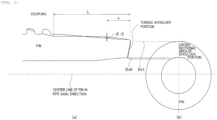
- Fig. 5 is a schematic view of a vicinity of a nose portion which is an extension portion of a pin.
- Fig. 5(a) is a cut sectional view of the pin and a coupling fastening portion parallel to the pipe axial direction
- Fig. 5(b) is a torque shoulder portion when a thread tip end portion of the pin is viewed from a front of a pin tip end portion.
- the cross-sectional area of the tip end thickness (part that receives the tip end of the male thread on the coupling side, (Ds1 - Ds0)/2), which is the torque shoulder portion of the male thread (pin) illustrated in FIG. 5 may be secured at 25% or more with respect to the cross-sectional area of the raw pipe.
- the tip end thickness which is the torque shoulder portion of the male thread is increased, since the nose rigidity is too high and seizure is likely to occur during tightening, the preferable range is 25 to 60%.
- the sealing property indicating airtightness is also important as a characteristic of the thread, and it is preferable to satisfy the compression rate of 85% or more illustrated in the sealing test of ISO 13679: 2019, which can be realized by using the bending and bending back cold processing of the present invention for increasing the strength.
- the nose length L which is the unthreaded portion at the tip end of the pin, is 0.3 inch or more, and the ratio x/L to the nose length L when the seal point position from the pipe end is x, is preferably 0.2 or more and 0.5 or less.
- the nose length L is 1.0 inch or less.
- the bending and bending back processing was performed by rotating the roll that have a rotation axis tilted 2 to 5° with respect to the pipe axial direction and are disposed at 120° intervals in the pipe circumferential direction to pull in the pipe and applying bending and bending back deformation.
- the pipe passing through the roll having the roll gap reduced by 5 to 15% with respect to the initial outer diameter of the pipe was bent and bent back.
- the yield strength characteristics in the pipe axial direction (pipe axis tensile yield strength in the pipe axial direction (pipe axial tensile yield strength), and compressive yield strength in the pipe axial direction (pipe axial compressive yield strength)) and the inclination angle ⁇ were measured.
- the inclination angle ⁇ is an inclination angle with respect to the pipe axial direction of a line segment formed by connecting one end and the other end of the thin-walled portion along the pipe surface with the shortest distance in the formation direction of the thin-walled portion.
- one end and the other end of the thin-walled portion were set from the region in the pipe selected with a shorter length between (1) the length of 1.0 m in the pipe axial direction and (2) 90% of the length in the pipe axial direction where the thin-walled portion turns once in the pipe circumferential direction.
- the inclination angle ⁇ was measured with the central portion in the length direction of the pipe as the center in the length direction of the measurement target region.
- the above inclination angle ⁇ was calculated by measuring the wall thickness distribution by ultrasonic waves in the state of the product length, and based on the maximum wall thickness t max [mm], the minimum wall thickness t min [mm], the average wall thickness t ave [mm] for the entire pipe, and the uneven wall thickness distribution at the time of piercing rolling by the Fourier transform using the distribution thereof.
- the average wall thickness t ave is obtained by measuring 32 points of the wall thickness t at intervals of 11.25° in the pipe circumferential direction starting from the thin-walled portion in the central portion in the length direction of the pipe and calculating the average of these numbers.
- the bending moment was applied so that the axial tensile stress on the outer surface of the pipe was constant at 80% with respect to the axial tensile yield strength of the pipe obtained by the tensile test.
- the collapse strength was determined by the pressure at the point where the fluctuation of the water pressure was confirmed, similarly to the conditions a and b.
- a threaded joint including a pin (pipe size) having an outer diameter of ⁇ 88.9 mm and a wall thickness t of 6.5 mm and a corresponding coupling, and a threaded joint including a pin having an outer diameter of ⁇ 244.5 mm and a wall thickness t of 13.8 mm and a corresponding coupling were prepared.
- a joint including only threads and a premium joint including threads, a metal-to-metal seal portion, and a shoulder portion were prepared, and the above-described fatigue test was performed.
- Table 4 illustrates the radius of curvature of the corner portion R of the load flank and the stabbing flank of the thread bottom of the pin, and the radius of curvature of the corner portion R of the load flank and the stabbing flank of the thread bottom of the coupling.
- Pipe No. Material Steel pipe size (pin)
- Types of thread Thread test No. Radius of curvature of corner portion (mm)
- Fatigue test results Load flank of pin Stabbing flank of pin Load flank of coupling Stabbing flank of coupling Relative comparison No.
- the Yield torque is 4000 N ⁇ m or more, and a sufficiently high torque can be secured and tightened.
- This feature can increase the degree of freedom in threaded joint design and enables the realization of the following two types of high performance threaded joints.
- the nose length L which is the unthreaded portion at the tip end of the pin, is 0.2 inch or more and 0.5 inch or less, and the ratio x/L to the nose length L when the seal point position from the pipe end is x, is designed to be 0.01 or more and 0.1 or less.
Landscapes
- Engineering & Computer Science (AREA)
- Mechanical Engineering (AREA)
- General Engineering & Computer Science (AREA)
- Chemical & Material Sciences (AREA)
- Thermal Sciences (AREA)
- Crystallography & Structural Chemistry (AREA)
- Physics & Mathematics (AREA)
- Materials Engineering (AREA)
- Metallurgy (AREA)
- Organic Chemistry (AREA)
- Manufacturing & Machinery (AREA)
- Heat Treatment Of Steel (AREA)
- Rigid Pipes And Flexible Pipes (AREA)
- Metal Extraction Processes (AREA)
Applications Claiming Priority (2)
| Application Number | Priority Date | Filing Date | Title |
|---|---|---|---|
| JP2020030531 | 2020-02-26 | ||
| PCT/JP2021/001455 WO2021171826A1 (ja) | 2020-02-26 | 2021-01-18 | 継目無管およびその製造方法 |
Publications (3)
| Publication Number | Publication Date |
|---|---|
| EP4094856A1 EP4094856A1 (en) | 2022-11-30 |
| EP4094856A4 EP4094856A4 (en) | 2023-10-04 |
| EP4094856B1 true EP4094856B1 (en) | 2025-04-16 |
Family
ID=77489956
Family Applications (1)
| Application Number | Title | Priority Date | Filing Date |
|---|---|---|---|
| EP21760889.2A Active EP4094856B1 (en) | 2020-02-26 | 2021-01-18 | Seamless tube and method for manufacturing same |
Country Status (6)
| Country | Link |
|---|---|
| US (1) | US12140265B2 (https=) |
| EP (1) | EP4094856B1 (https=) |
| JP (1) | JP7156514B2 (https=) |
| CN (1) | CN115151353B (https=) |
| MX (1) | MX2022010478A (https=) |
| WO (1) | WO2021171826A1 (https=) |
Family Cites Families (21)
| Publication number | Priority date | Publication date | Assignee | Title |
|---|---|---|---|---|
| US1960557A (en) * | 1931-04-22 | 1934-05-29 | Tube Turns Inc | Pipe fitting |
| US4218814A (en) * | 1979-04-09 | 1980-08-26 | Dart Industries Inc. | Method of insulating conduit |
| JPS56168903A (en) * | 1980-06-02 | 1981-12-25 | Nippon Steel Corp | Rolling method for correcting thickness deviation of seamless steel pipe |
| JPS597425A (ja) * | 1982-07-05 | 1984-01-14 | Kawasaki Steel Corp | 鋼管の肉厚測定方法 |
| JPH0692006B2 (ja) * | 1987-07-28 | 1994-11-16 | 住友金属工業株式会社 | 穿孔圧延方法 |
| JP2515182B2 (ja) | 1991-05-21 | 1996-07-10 | 秩父小野田株式会社 | ムライト粉末原料及びその製造方法並びにムライト粉末の製造方法 |
| JPH07265910A (ja) * | 1994-03-29 | 1995-10-17 | Kawasaki Steel Corp | 継目無管の製造方法 |
| JPH1157842A (ja) * | 1997-08-27 | 1999-03-02 | Sumitomo Metal Ind Ltd | 管軸長方向の圧縮強度に優れた鋼管の製造方法 |
| JP2001009508A (ja) * | 1999-06-29 | 2001-01-16 | Kawasaki Steel Corp | 丸鋼鋳片の穿孔方法 |
| JP4367091B2 (ja) * | 2002-12-20 | 2009-11-18 | Jfeスチール株式会社 | 耐疲労特性に優れ、かつ強度−延性バランスに優れた高強度熱延鋼板およびその製造方法 |
| FI115484B (fi) * | 2003-02-25 | 2005-05-13 | Kwh Pipe Ab Oy | Putken valmistuksessa käytettävä onteloprofiili |
| JP5786351B2 (ja) * | 2011-02-15 | 2015-09-30 | Jfeスチール株式会社 | 耐コラプス性能の優れたラインパイプ用鋼管 |
| JP5137048B2 (ja) * | 2011-03-24 | 2013-02-06 | 新日鐵住金株式会社 | オーステナイト系合金管及びその製造方法 |
| JP5831195B2 (ja) | 2011-12-14 | 2015-12-09 | Jfeスチール株式会社 | 継目無鋼管製造におけるホローシェルサポート装置及びサポート方法 |
| JP5500324B1 (ja) * | 2012-08-31 | 2014-05-21 | 新日鐵住金株式会社 | 二相ステンレス鋼管及びその製造方法 |
| US20170122468A1 (en) | 2014-05-30 | 2017-05-04 | Nippon Steel & Sumitomo Metal Corporation | Threaded joint for steel pipes |
| WO2016113790A1 (ja) * | 2015-01-15 | 2016-07-21 | Jfeスチール株式会社 | 管用ねじ継手 |
| JP6596954B2 (ja) | 2015-06-12 | 2019-10-30 | 日本製鉄株式会社 | 継目無鋼管及びその製造方法 |
| JP6432614B2 (ja) * | 2016-02-08 | 2018-12-05 | Jfeスチール株式会社 | 金属管の冷間圧延方法および製造方法 |
| UA122027C2 (uk) * | 2016-08-24 | 2020-08-25 | ДжФЕ СТІЛ КОРПОРЕЙШН | Різьбове з'єднання для трубних виробів нафтопромислового сортаменту |
| WO2019198459A1 (ja) * | 2018-04-09 | 2019-10-17 | 日本製鉄株式会社 | 鋼管、及び、鋼管の製造方法 |
-
2021
- 2021-01-18 WO PCT/JP2021/001455 patent/WO2021171826A1/ja not_active Ceased
- 2021-01-18 EP EP21760889.2A patent/EP4094856B1/en active Active
- 2021-01-18 JP JP2021516501A patent/JP7156514B2/ja active Active
- 2021-01-18 CN CN202180016638.2A patent/CN115151353B/zh active Active
- 2021-01-18 US US17/800,963 patent/US12140265B2/en active Active
- 2021-01-18 MX MX2022010478A patent/MX2022010478A/es unknown
Also Published As
| Publication number | Publication date |
|---|---|
| CN115151353B (zh) | 2025-07-04 |
| EP4094856A4 (en) | 2023-10-04 |
| JP7156514B2 (ja) | 2022-10-19 |
| EP4094856A1 (en) | 2022-11-30 |
| US12140265B2 (en) | 2024-11-12 |
| BR112022016623A2 (pt) | 2022-10-11 |
| JPWO2021171826A1 (https=) | 2021-09-02 |
| CN115151353A (zh) | 2022-10-04 |
| WO2021171826A1 (ja) | 2021-09-02 |
| US20230079996A1 (en) | 2023-03-16 |
| MX2022010478A (es) | 2022-09-19 |
Similar Documents
| Publication | Publication Date | Title |
|---|---|---|
| JP7095811B2 (ja) | 合金管およびその製造方法 | |
| EP2853614B1 (en) | Duplex stainless steel tube and method for producing same | |
| US12516391B2 (en) | Stainless steel seamless pipe and method for manufacturing same | |
| TWI700136B (zh) | 方鋼管的製造方法及方鋼管 | |
| US20200130035A1 (en) | Method for producing a high-pressure pipe | |
| US12331371B2 (en) | Stainless steel pipe and method for manufacturing same | |
| EP3225319B1 (en) | Method for manufacturing rifled tube | |
| EP3173764B1 (en) | Steel sulfide-stress-cracking test method and seamless steel pipe having excellent sulfide-stress-cracking resistance | |
| KR102830472B1 (ko) | 전봉 강관, 그 제조 방법 및 자동차용 구조 부재 | |
| EP4094856B1 (en) | Seamless tube and method for manufacturing same | |
| US12359752B2 (en) | Stainless steel pipe and method for manufacturing same | |
| JP4903635B2 (ja) | 変形能に優れたラインパイプ用uoe鋼管 | |
| RU2334910C1 (ru) | Стальной баллон высокого давления и способ его изготовления | |
| JP2595856B2 (ja) | 継目無クラッド金属管の製造方法 | |
| JP2003340518A (ja) | 圧潰強度に優れたuoe鋼管の製造方法 | |
| JPH1157842A (ja) | 管軸長方向の圧縮強度に優れた鋼管の製造方法 | |
| BR112022016623B1 (pt) | Tubo sem emendas e método para fabricar o mesmo | |
| JP4720344B2 (ja) | 鋼管、該鋼管を用いたパイプライン | |
| JP7647732B2 (ja) | 金属管の圧延方法、金属管の製造方法及び圧延設備 | |
| JPH1080715A (ja) | 冷間加工のままで使用される鋼管の製造方法 | |
| JP6222126B2 (ja) | 電縫鋼管およびその製造方法 | |
| JP2018047506A (ja) | 電縫鋼管およびその製造方法 | |
| BR112022016509B1 (pt) | Tubo de aço inoxidável e método para fabricá-lo | |
| BR112022014826B1 (pt) | Tubo sem costura de aço inoxidável e método para fabricar o mesmo |
Legal Events
| Date | Code | Title | Description |
|---|---|---|---|
| STAA | Information on the status of an ep patent application or granted ep patent |
Free format text: STATUS: THE INTERNATIONAL PUBLICATION HAS BEEN MADE |
|
| PUAI | Public reference made under article 153(3) epc to a published international application that has entered the european phase |
Free format text: ORIGINAL CODE: 0009012 |
|
| STAA | Information on the status of an ep patent application or granted ep patent |
Free format text: STATUS: REQUEST FOR EXAMINATION WAS MADE |
|
| 17P | Request for examination filed |
Effective date: 20220822 |
|
| AK | Designated contracting states |
Kind code of ref document: A1 Designated state(s): AL AT BE BG CH CY CZ DE DK EE ES FI FR GB GR HR HU IE IS IT LI LT LU LV MC MK MT NL NO PL PT RO RS SE SI SK SM TR |
|
| DAV | Request for validation of the european patent (deleted) | ||
| DAX | Request for extension of the european patent (deleted) | ||
| RIC1 | Information provided on ipc code assigned before grant |
Ipc: B21B 37/78 20060101ALI20230530BHEP Ipc: F16L 15/04 20060101ALI20230530BHEP Ipc: C21D 7/02 20060101ALI20230530BHEP Ipc: B21B 19/02 20060101AFI20230530BHEP |
|
| A4 | Supplementary search report drawn up and despatched |
Effective date: 20230906 |
|
| RIC1 | Information provided on ipc code assigned before grant |
Ipc: B21B 37/78 20060101ALI20230831BHEP Ipc: F16L 15/04 20060101ALI20230831BHEP Ipc: C21D 7/02 20060101ALI20230831BHEP Ipc: B21B 19/02 20060101AFI20230831BHEP |
|
| GRAP | Despatch of communication of intention to grant a patent |
Free format text: ORIGINAL CODE: EPIDOSNIGR1 |
|
| STAA | Information on the status of an ep patent application or granted ep patent |
Free format text: STATUS: GRANT OF PATENT IS INTENDED |
|
| INTG | Intention to grant announced |
Effective date: 20241213 |
|
| GRAS | Grant fee paid |
Free format text: ORIGINAL CODE: EPIDOSNIGR3 |
|
| GRAA | (expected) grant |
Free format text: ORIGINAL CODE: 0009210 |
|
| STAA | Information on the status of an ep patent application or granted ep patent |
Free format text: STATUS: THE PATENT HAS BEEN GRANTED |
|
| AK | Designated contracting states |
Kind code of ref document: B1 Designated state(s): AL AT BE BG CH CY CZ DE DK EE ES FI FR GB GR HR HU IE IS IT LI LT LU LV MC MK MT NL NO PL PT RO RS SE SI SK SM TR |
|
| REG | Reference to a national code |
Ref country code: GB Ref legal event code: FG4D |
|
| REG | Reference to a national code |
Ref country code: CH Ref legal event code: EP Ref country code: DE Ref legal event code: R096 Ref document number: 602021029277 Country of ref document: DE |
|
| REG | Reference to a national code |
Ref country code: IE Ref legal event code: FG4D |
|
| REG | Reference to a national code |
Ref country code: NL Ref legal event code: MP Effective date: 20250416 |
|
| PG25 | Lapsed in a contracting state [announced via postgrant information from national office to epo] |
Ref country code: NL Free format text: LAPSE BECAUSE OF FAILURE TO SUBMIT A TRANSLATION OF THE DESCRIPTION OR TO PAY THE FEE WITHIN THE PRESCRIBED TIME-LIMIT Effective date: 20250416 |
|
| REG | Reference to a national code |
Ref country code: AT Ref legal event code: MK05 Ref document number: 1785241 Country of ref document: AT Kind code of ref document: T Effective date: 20250416 |
|
| PG25 | Lapsed in a contracting state [announced via postgrant information from national office to epo] |
Ref country code: FI Free format text: LAPSE BECAUSE OF FAILURE TO SUBMIT A TRANSLATION OF THE DESCRIPTION OR TO PAY THE FEE WITHIN THE PRESCRIBED TIME-LIMIT Effective date: 20250416 Ref country code: PT Free format text: LAPSE BECAUSE OF FAILURE TO SUBMIT A TRANSLATION OF THE DESCRIPTION OR TO PAY THE FEE WITHIN THE PRESCRIBED TIME-LIMIT Effective date: 20250818 Ref country code: ES Free format text: LAPSE BECAUSE OF FAILURE TO SUBMIT A TRANSLATION OF THE DESCRIPTION OR TO PAY THE FEE WITHIN THE PRESCRIBED TIME-LIMIT Effective date: 20250416 |
|
| REG | Reference to a national code |
Ref country code: LT Ref legal event code: MG9D |
|
| PG25 | Lapsed in a contracting state [announced via postgrant information from national office to epo] |
Ref country code: NO Free format text: LAPSE BECAUSE OF FAILURE TO SUBMIT A TRANSLATION OF THE DESCRIPTION OR TO PAY THE FEE WITHIN THE PRESCRIBED TIME-LIMIT Effective date: 20250716 Ref country code: GR Free format text: LAPSE BECAUSE OF FAILURE TO SUBMIT A TRANSLATION OF THE DESCRIPTION OR TO PAY THE FEE WITHIN THE PRESCRIBED TIME-LIMIT Effective date: 20250717 |
|
| PG25 | Lapsed in a contracting state [announced via postgrant information from national office to epo] |
Ref country code: PL Free format text: LAPSE BECAUSE OF FAILURE TO SUBMIT A TRANSLATION OF THE DESCRIPTION OR TO PAY THE FEE WITHIN THE PRESCRIBED TIME-LIMIT Effective date: 20250416 |
|
| PG25 | Lapsed in a contracting state [announced via postgrant information from national office to epo] |
Ref country code: BG Free format text: LAPSE BECAUSE OF FAILURE TO SUBMIT A TRANSLATION OF THE DESCRIPTION OR TO PAY THE FEE WITHIN THE PRESCRIBED TIME-LIMIT Effective date: 20250416 |
|
| PG25 | Lapsed in a contracting state [announced via postgrant information from national office to epo] |
Ref country code: HR Free format text: LAPSE BECAUSE OF FAILURE TO SUBMIT A TRANSLATION OF THE DESCRIPTION OR TO PAY THE FEE WITHIN THE PRESCRIBED TIME-LIMIT Effective date: 20250416 |
|
| PG25 | Lapsed in a contracting state [announced via postgrant information from national office to epo] |
Ref country code: AT Free format text: LAPSE BECAUSE OF FAILURE TO SUBMIT A TRANSLATION OF THE DESCRIPTION OR TO PAY THE FEE WITHIN THE PRESCRIBED TIME-LIMIT Effective date: 20250416 |
|
| PG25 | Lapsed in a contracting state [announced via postgrant information from national office to epo] |
Ref country code: RS Free format text: LAPSE BECAUSE OF FAILURE TO SUBMIT A TRANSLATION OF THE DESCRIPTION OR TO PAY THE FEE WITHIN THE PRESCRIBED TIME-LIMIT Effective date: 20250716 |
|
| PG25 | Lapsed in a contracting state [announced via postgrant information from national office to epo] |
Ref country code: IS Free format text: LAPSE BECAUSE OF FAILURE TO SUBMIT A TRANSLATION OF THE DESCRIPTION OR TO PAY THE FEE WITHIN THE PRESCRIBED TIME-LIMIT Effective date: 20250816 |
|
| PG25 | Lapsed in a contracting state [announced via postgrant information from national office to epo] |
Ref country code: LV Free format text: LAPSE BECAUSE OF FAILURE TO SUBMIT A TRANSLATION OF THE DESCRIPTION OR TO PAY THE FEE WITHIN THE PRESCRIBED TIME-LIMIT Effective date: 20250416 |
|
| PG25 | Lapsed in a contracting state [announced via postgrant information from national office to epo] |
Ref country code: SM Free format text: LAPSE BECAUSE OF FAILURE TO SUBMIT A TRANSLATION OF THE DESCRIPTION OR TO PAY THE FEE WITHIN THE PRESCRIBED TIME-LIMIT Effective date: 20250416 Ref country code: DK Free format text: LAPSE BECAUSE OF FAILURE TO SUBMIT A TRANSLATION OF THE DESCRIPTION OR TO PAY THE FEE WITHIN THE PRESCRIBED TIME-LIMIT Effective date: 20250416 |
|
| REG | Reference to a national code |
Ref country code: DE Ref legal event code: R097 Ref document number: 602021029277 Country of ref document: DE |
|
| PG25 | Lapsed in a contracting state [announced via postgrant information from national office to epo] |
Ref country code: CZ Free format text: LAPSE BECAUSE OF FAILURE TO SUBMIT A TRANSLATION OF THE DESCRIPTION OR TO PAY THE FEE WITHIN THE PRESCRIBED TIME-LIMIT Effective date: 20250416 |
|
| PG25 | Lapsed in a contracting state [announced via postgrant information from national office to epo] |
Ref country code: EE Free format text: LAPSE BECAUSE OF FAILURE TO SUBMIT A TRANSLATION OF THE DESCRIPTION OR TO PAY THE FEE WITHIN THE PRESCRIBED TIME-LIMIT Effective date: 20250416 |
|
| PG25 | Lapsed in a contracting state [announced via postgrant information from national office to epo] |
Ref country code: SK Free format text: LAPSE BECAUSE OF FAILURE TO SUBMIT A TRANSLATION OF THE DESCRIPTION OR TO PAY THE FEE WITHIN THE PRESCRIBED TIME-LIMIT Effective date: 20250416 |
|
| PLBE | No opposition filed within time limit |
Free format text: ORIGINAL CODE: 0009261 |
|
| STAA | Information on the status of an ep patent application or granted ep patent |
Free format text: STATUS: NO OPPOSITION FILED WITHIN TIME LIMIT |
|
| REG | Reference to a national code |
Ref country code: CH Ref legal event code: L10 Free format text: ST27 STATUS EVENT CODE: U-0-0-L10-L00 (AS PROVIDED BY THE NATIONAL OFFICE) Effective date: 20260225 |
|
| 26N | No opposition filed |
Effective date: 20260119 |