EP4091925B1 - Dispositif d'acheminement d'au moins un tuyau flexible dans un véhicule à volant - Google Patents
Dispositif d'acheminement d'au moins un tuyau flexible dans un véhicule à volant Download PDFInfo
- Publication number
- EP4091925B1 EP4091925B1 EP22173486.6A EP22173486A EP4091925B1 EP 4091925 B1 EP4091925 B1 EP 4091925B1 EP 22173486 A EP22173486 A EP 22173486A EP 4091925 B1 EP4091925 B1 EP 4091925B1
- Authority
- EP
- European Patent Office
- Prior art keywords
- spiral
- line
- tube
- guide
- lines
- Prior art date
- Legal status (The legal status is an assumption and is not a legal conclusion. Google has not performed a legal analysis and makes no representation as to the accuracy of the status listed.)
- Active
Links
Images


Classifications
-
- B—PERFORMING OPERATIONS; TRANSPORTING
- B62—LAND VEHICLES FOR TRAVELLING OTHERWISE THAN ON RAILS
- B62K—CYCLES; CYCLE FRAMES; CYCLE STEERING DEVICES; RIDER-OPERATED TERMINAL CONTROLS SPECIALLY ADAPTED FOR CYCLES; CYCLE AXLE SUSPENSIONS; CYCLE SIDE-CARS, FORECARS, OR THE LIKE
- B62K19/00—Cycle frames
- B62K19/30—Frame parts shaped to receive other cycle parts or accessories
- B62K19/32—Steering heads
-
- B—PERFORMING OPERATIONS; TRANSPORTING
- B62—LAND VEHICLES FOR TRAVELLING OTHERWISE THAN ON RAILS
- B62J—CYCLE SADDLES OR SEATS; AUXILIARY DEVICES OR ACCESSORIES SPECIALLY ADAPTED TO CYCLES AND NOT OTHERWISE PROVIDED FOR, e.g. ARTICLE CARRIERS OR CYCLE PROTECTORS
- B62J11/00—Supporting arrangements specially adapted for fastening specific devices to cycles, e.g. supports for attaching maps
- B62J11/10—Supporting arrangements specially adapted for fastening specific devices to cycles, e.g. supports for attaching maps for mechanical cables, hoses, pipes or electric wires, e.g. cable guides
- B62J11/19—Supporting arrangements specially adapted for fastening specific devices to cycles, e.g. supports for attaching maps for mechanical cables, hoses, pipes or electric wires, e.g. cable guides specially adapted for electric wires
Definitions
- the invention relates to a device for guiding at least one flexible line in the annular space between a head tube of a vehicle frame and a fork shaft of a handlebar fork that is rotatably mounted in the head tube.
- the invention further relates to the use of such a device for guiding lines as well as two-, three- and four-wheelers that are equipped with such a device.
- the handlebar is connected via a fork shaft to a handlebar fork, which is connected directly or via a suspension to a front wheel of the vehicle.
- the fork shaft is rotatably mounted in a head tube, which is part of a vehicle frame.
- flexible cables that run from the fork and handlebar area to the frame have mostly been routed on the outside of these components because routing them inside is problematic due to the relative movement between the head tube/vehicle frame on the one hand and the fork shaft/fork/handlebar on the other (rotations of up to +/- 180° and more).
- power-carrying cables especially for lighting
- hydraulic lines for braking or suspension devices or Bowden cables but increasingly also signal lines for controlling electronic components.
- "flexible” cables are understood to mean cables for power, signals, light, hydraulic oil or steel cables (Bowden cables) that are not rigid, i.e. can be elastically deformed.
- the cables can be single- or multi-core, or several different or even different types of cables can be brought together.
- a cable guide for a two-wheeler is known in which a sleeve or cuff is arranged in the annular space between the head tube and the fork shaft, which prevents the cables from rubbing against the inner fork shaft when the steering is turned.
- the US 2019/0061864 A1 discloses a telescopic handlebar arrangement for two-wheelers, in which spiral lines are guided inside the inner telescopic shaft in order to compensate for changes in length between the two ends of the shaft elements which are axially telescopic relative to one another, whereby a rubbing and thus wearing contact between the spiral line and the surrounding shaft inner wall is not prevented.
- a guide device for flexible cables according to the preamble of claim 1 is known, in which the cable is guided in a guide channel formed from two half-shells in a semicircle in the circumferential direction.
- a guide device for flexible lines according to the preamble of claim 1 is known, which consists of two ring elements spaced apart in the axial direction with radial passage openings for the line, wherein the line is guided between the two ring elements in the axial direction in the annular space between the steering tube and the fork shaft.
- US 2010/0194073 A1 discloses a guide for Bowden cables of a two-wheeler, which has several concentric rings between which a vertical cable routing is possible.
- the object of the invention is to provide a structurally simple device for the protected or concealed guidance of at least one flexible cable in the area of a fork shaft inside a vehicle frame.
- the movements of the cable that occur should not lead to damage to the cable and restoring forces due to deformation of the cable should be largely avoided.
- the device forms at least one shaped element for forming at least a partial helical guide of at least one turn for the at least one line in the annular space.
- the shaped element has the shape of a helical screw.
- a plurality of individual projections can be provided, the sequence or attachment of which causes the at least one line to wrap around the fork shaft in a spiral or helical arrangement with at least one turn.
- the length of the cable does not change for the relative rotational movement, i.e. there is no extension or compression, only the diameter of the spiral changes.
- the rotational movement of the fork in the head tube is compensated for or bridged by the expansion or contraction of the spiral turns of the cable. If a maximum rotation range of the handlebars in one direction of 180° is assumed, this is half a turn. With a helical guide channel of one turn, twice the space (360° compared to 180° with maximum rotation of the handlebars) is available for the cable to be pushed together or pulled apart.
- the cable must be wound loosely in the guide channel to absorb the rotational movement of +/- 180°, or it must be wound tightly in an end position that corresponds to an end position of the handlebar rotation (e.g. rotated 180° from the straight-ahead position).
- the handlebar/steerer tube is turned back to the opposite end position (e.g. -180°)
- the arrangement is preferably selected so that the spiral-shaped cable is in a relaxed state when the handlebars are in a "straight ahead" position.
- slight restoring forces can occur due to the expansion or contraction of the cable spiral, but these can be kept to a minimum by giving the cable wall or components a suitably smooth shape.
- the shape of the guide prevents individual spiral threads from being thrown over. If a vehicle with a handlebar fork is mentioned in this context, this typically means that a manually operated handlebar is attached to the top of the handlebar fork, as is the case with almost every bicycle or motorcycle.
- the invention can also be applied to vehicles in which the handlebar fork does not have a handlebar, but is connected to a separately guided handlebar via a coupling, such as cargo bikes or child transport bikes in which the transport space is arranged behind the front wheel or the handlebar fork but in front of the handlebar.
- the device is designed with multiple threads for different lines.
- Each screw thread can have its own line that does not collide with another line in another helix thread, which reduces the risk of damage during long-term use.
- the helical guides for two cables are arranged axially one behind the other.
- the two cables can be arranged axially one behind the other completely separately from one another.
- This design requires larger axial installation space, but a narrow annular gap between the head tube and the fork shaft.
- the helical guides for two cables are arranged radially one above the other. This design requires less axial installation space, but a wider annular gap between the head tube and the fork shaft.
- each guide has at least 3, preferably between 4 and 12, particularly preferably 5 to 8 turns.
- the device consists of an inner structure and an outer sleeve, between which the spiral surface (36) extends.
- the line is thus arranged in a protected manner inside the device.
- the outer sleeve can be pushed onto the inner sleeve or the spiral surface.
- the inner structure preferably has an axial end cover at one axial end and the outer sleeve at the other axial end in order to prevent the ingress of foreign bodies and dirt.
- the upper end cover is attached to the inner structure and the lower end cover is attached to the outer sleeve.
- an upper line opening for the passage of the at least one line is formed in the upper end cover.
- a lower line opening for the passage of the at least one line is arranged near the lower end cover in the outer sleeve.
- the upper end cover can also be connected to the outer sleeve and the lower end cover to the inner sleeve.
- spiral surface can also be attached or molded onto the outer shell and protrude inwards.
- the device is designed as flexible spiral tube, the first end of which is fixed to the head tube and the second end to the fork shaft.
- the cable remains almost unchanged in terms of location compared to the spiral tube and both deform elastically together, reducing or increasing the winding diameter.
- the spiral tube has a longitudinal slot which is preferably arranged on the outside of the spiral tube and is closed in the normal state, i.e. is opened by elastically bending the edges of the slot apart in order to insert the cable.
- the slot then closes by elastically moving the edges of the slot back to the starting position so that the cable can no longer escape during use.
- the device is designed as a multi-part sleeve with guide projections formed on the outer circumference, which lie on a spiral line on the circumference of the sleeve.
- the line is laid in a spiral shape between the preferably pin-like projections.
- the projections or pins have such a radial extension that the line cannot protrude radially beyond the projections during maximum deformation.
- guide projections are molded directly onto the fork shaft, i.e. they are created during the manufacturing process of the fork shaft.
- the device is designed as a spiral spring, the first end of which is fixed to the head tube and the second end to the fork shaft, and the at least one line can be fastened to the spiral spring, for example by means of cable ties.
- the spiral spring and the line also form a jointly moving component.
- the spiral spring consists of a spring steel or a plastic spiral.
- the design made of Spring steel is more space-saving and durable, the plastic version is easier to produce if sufficient quantities are required and can advantageously have fastening elements for the cable molded on.
- the invention further relates to a two-wheeler which has a device according to the invention mounted according to one or more aspects or embodiments. These include bicycles, e-bikes, pedelecs or two-wheeled cargo bikes.
- the invention further relates to a tricycle which has a device according to the invention mounted according to one or more aspects or embodiments. These include children's tricycles, three-wheeled cargo bikes and motor-driven so-called trikes.
- the invention further relates to a four-wheeled vehicle with a handlebar, such as a four-wheeled cargo bike or a quad, which has a device according to the invention mounted according to one or more aspects or embodiments.
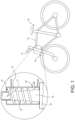
- Figure 1 shows a vehicle frame 10 of a two-wheeler 12, the front end of which has a head tube 14 in which a fork shaft 16 of a handlebar fork 18 is rotatably mounted.
- the vehicle frame 10 has at least one bore 20 for the passage of a flexible line 22, which is located in an annular space 23 between the head tube 14 and the fork shaft 16 and should not be damaged when the handlebar fork 18 rotates relative to the vehicle frame 10.
- the fork shaft 16 has a bore 21 for the passage of the line 22 into the interior of the fork shaft 16 and for further routing upwards.
- the cable 22 can be a current-carrying cable, e.g. for lighting or a hydraulic cable for brakes or hydraulic suspension, fiber optic cables or Bowden cables. It can also be a signal cable for controlling electronic devices.
- the cable 22 can be single- or multi-core, or several different or even different types of cables 22a, 22b can be combined.
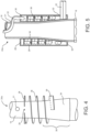
- Figure 2 shows a perspective view of a first embodiment of a cable guide device 24a according to the invention, of which an outer sleeve 26 and an upper front cover 28 with an upper opening 30 for the passage of the cable 22, which is designed as a two-wire cable, as well as a lower opening 32 for the same cable 22 are shown in this figure.
- the bore 21 for the passage of the flexible cable 22 into the interior of the fork shaft 16 is formed in the fork shaft 16.
- the bore 21 and the opening 30 are preferably located one behind the other in the axial direction. It should be noted that the invention does not require a cable to be guided into the interior of the fork shaft 16, but the cable 22 can also be guided upwards outside next to the fork shaft 16, in which case the bore 21 is of course omitted.
- FIG 3 the same device 24a is shown without the outer sleeve 26.
- a sleeve-like inner structure (inner sleeve) 34 can be seen, which encloses the fork shaft 16 in such a way that the inner sleeve 34 rotates with each rotation of the fork shaft 16. This can be done by means of a form fit or friction fit or by gluing or by fastening with a screw.
- the inner structure 34 does not have to be a sleeve, it can also be a ring-shaped grid structure.
- the upper end cover 28 is molded onto the inner structure/inner sleeve 34.
- a single spiral surface 36 is shown for forming a guide channel for a line 22.
- a collar 39 is shown in dashed lines, which in an alternative embodiment, which dispenses with an outer sleeve 26, would be arranged along the outer edge of the entire spiral surface 36, and thus represents a radial outer stop for the line 22.
- the outer sleeve 26 is attached to the head tube 14 in a form-fitting or force-fitting manner using fixing means (not shown) and is thus firmly connected to the vehicle frame 10.
- the "outer sleeve” can also be part of the frame or be completely omitted.
- the inner sleeve 34 and the spiral surface 36 are connected to the fork shaft 16 in a rotationally fixed manner and rotate when the handlebar is operated. This creates a rotational relative movement between the spiral surface 36 and the outer sleeve 26 and thus also between the upper 30 and lower 32 openings when the steering is turned.
- Outer sleeve 26 is arranged in the head tube 14 such that the bore 20 ( Figure 1 ) is aligned with the lower opening 32, so that the part of the line 22 exiting through the lower opening 32 passes through the bore 20 ( Figure 1 ) can be carried out.
- the line 22 is guided between the spiral surface 36 approximately spatially radially in the middle between the inner sleeve 34 and the outer sleeve 26 (the inner sleeve 34 and the outer sleeve 26 and the spiral surface 36 together form a guide or a channel for the line), so that when the handlebars move due to the relative rotation between the inner sleeve 34 and the outer sleeve 26, in one case the line 22 is pulled and then clings more closely to the inner sleeve 34, and in the other case it is pressed so that the spiral radius of the line 22 increases slightly and it comes closer to the outer sleeve 26, especially in the upper area.
- the line 22 is fixed in the area of the two openings 30, 32 to the associated components 34, 26 (or the bore 20 and the bore 21) using fixing means not shown in detail (e.g. cable ties), so that the movement of the line 22 takes place exclusively inside the device 24a.
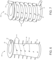
- a second embodiment of a cable guide device 24b is shown in the Figures 6 and 7 shown in Figure 6 without and in Figure 7 with the line 22.
- This design differs from the first embodiment of a line guide device 24a in that there is no spiral surface and instead preferably pin-like guide projections 44 protrude outwards from the sleeve 42, which lie on a spiral line 46 and thus ensure that the line 22 is guided between the pins 44.
- the pins 44 can be aligned radially, but can also run obliquely to the central axis.
- the pins 44 can also be straight, but can also have a different (preferably curved or hook-like) shape.
- this design 24b comprises, in the same way as the first embodiment 24a, an additional (not shown) outer sleeve 26 in order to form a closed shape for the line 22.
- the outer sleeve 26 can be omitted.
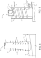
- FIG. 8 A third embodiment of a cable guide device 24c is shown in Figure 8 shown, which is similar to the second embodiment 24b ( Figure 6 and 7 ), with the difference that a sleeve (34, 42) is completely dispensed with and instead pins 48 are formed directly on the fork shaft 16.
- the line (not shown) is attached to the top of the uppermost pin 48a (eg by means of a cable tie) and runs spirally underneath, surrounding the fork shaft 16 at a distance to the lowest pin 48b and runs from there into the bore 20 in the vehicle frame 10 ( Figure 1 ).
- the pins 48 have a sufficient radial length so that the center of the line 22 cannot under any circumstances protrude beyond the end of the pins 48.
- the pins 48 are preferably pressed into prefabricated holes on the circumference of the fork shaft.
- the pins 48 could also have an upwardly projecting hook end at the end, which prevents slipping off the pins 48.
- a fourth embodiment of a cable guide device 24d is shown in Figure 9 shown, which is designed as an elastic spiral tube 50, the lower end 52a of which is fastened to the vehicle frame 10 in the area of the bore 20 and the upper end 52b of which is fastened further up to the fork shaft 16, for example by means of a cable tie.
- the line 22 can be fastened in the bore 20 in the frame 10 and the bore 21 in the fork shaft 16 by means of a cable grommet 56.
- the spiral tube 50 has a sufficiently large diameter so that the line 22 can be pushed through.
- the longitudinal slot 54 is preferably not arranged on the radial outside of the spiral tube 50 with respect to the spiral direction so that the line 22 does not rub against the slot 54 and become damaged.
- Figure 10 shows a line guide device 24e for two separate flexible lines 22a, 22b, which are guided radially separated from one another and parallel to one another in two elastically rigid spiral tubes 50a, 50b, namely an outer line 22a and an inner line 22b separated by a separating sleeve 55.
- the separating sleeve 55 is not necessary but preferred in order to separate the two spiral tubes 50a, 50b.
- Both spiral tubes 50a, 50b enter through separate holes 20a, 20b through the head tube 14 into the annular space between the head tube 14 and the fork shaft 16 and through holes 21a, 21b into the interior of the fork shaft 16.
- the separating sleeve 55 is attached to the fork shaft 16. This requires a bore 57 for the passage of the outer line 22a.
- Figure 12 shows a further embodiment of a cable guide device 24g, in which two flexible cables 22a, 22b are guided axially one behind the other. These enter the head tube 14 via vertically spaced holes 20a, 20b and through equally spaced holes 21a, 21b into the interior of the fork shaft 16. In the embodiment shown, the cables have approximately 2.8 turns.
- the hole 20a for the passage of the upper flexible cable 22a is preferably located slightly above the hole 21b for the passage of the lower cable 22b in the fork shaft 16, in which they are continued upwards.
- Figure 13 shows a further embodiment of a cable guide device 24h similar to that of Figure 5 , in which a spiral surface 58 is formed on the outer sleeve 26 projecting inwards, so that an inner sleeve (34 in Figure 5 ) can be dispensed with.
- the spiral surface 58 formed on the outer sleeve 26 extends almost to the fork shaft 16 while maintaining a narrow slot of a few millimeters.
- the outer sleeve 26 is fixed to the head tube, for example by pressing in, gluing or other means such as screws, nuts or pins.
Landscapes
- Engineering & Computer Science (AREA)
- Mechanical Engineering (AREA)
- Steering Devices For Bicycles And Motorcycles (AREA)
- Flexible Shafts (AREA)
Claims (20)
- Dispositif, destiné à guider au moins un câble flexible dans l'espace annulaire (23) entre un tube de direction (14) d'un châssis (10) de véhicule et une tige de fourche (16) logée en rotation dans le tube de direction (14) d'une fourche de direction (18) d'un véhicule, caractérisé en ce qu'il constitue au moins un élément de formage (36, 44, 48) pour constituer au moins un guidage hélicoïdal avec au moins une convolution pour l'au moins un câble (22) dans l'espace annulaire.
- Dispositif selon la revendication 1, caractérisé en ce qu'il est conçu à filets multiples pour différents câbles (22, 22a, 22b).
- Dispositif selon la revendication 2, caractérisé en ce que les guidages hélicoïdaux pour deux câbles (22a, 22b) sont placés l'un derrière l'autre en direction axiale.
- Dispositif selon la revendication 2, caractérisé en ce que les guidages hélicoïdaux pour deux câbles (22a, 22b) sont placés en superposition en direction axiale.
- Dispositif selon l'une quelconque ou plusieurs des revendications précédentes, caractérisé en ce que chaque guidage comporte au moins 3, de préférence entre 4 et 12, de manière particulièrement préférentielle, de 5 à 8 convolutions.
- Dispositif selon l'une quelconque ou plusieurs des revendications précédentes, caractérisé en ce qu'il est constitué d'une structure interne (34) à partir de laquelle une surface hélicoïdale (36) s'étend vers l'extérieur en direction radiale.
- Dispositif selon la revendication 6, caractérisé en ce qu'il est constitué de la structure interne (34) et d'une douille externe (26) entre lesquelles s'étend la surface hélicoïdale (36).
- Dispositif selon la revendication 7, caractérisé en ce qu'il comprend un capuchon (28) d'extrémité supérieur en direction axiale et un capuchon (40) d'extrémité inférieur en direction axiale, dont l'un est surmoulé ou monté sur la structure interne (34) et l'autre sur la douille externe (26).
- Dispositif selon l'une quelconque ou plusieurs des revendications 1 à 5, caractérisé en ce qu'il est constitué d'une structure externe (26) à partir de laquelle une surface hélicoïdale (58) s'étend vers l'intérieur en direction radiale.
- Dispositif selon l'une quelconque ou plusieurs des revendications 1 à 5, caractérisé en ce qu'il est conçu sous la forme d'un serpentin (50) flexible, dont la première extrémité (52a) est fixée sur le tube de direction (14) et dont la deuxième extrémité (52b) est fixée sur la tige de fourche (16).
- Dispositif selon la revendication 10, caractérisé en ce que le serpentin (50) comporte une fente allongée (54) .
- Dispositif selon l'une quelconque des revendications 1 à 6, caractérisé en ce que ledit guidage comprend une douille (42) pourvue de saillies de guidage (44) surmoulées sur la circonférence externe, qui se situent sur une ligne en spirale (46) sur la circonférence de la douille (42).
- Dispositif selon la revendication 1, caractérisé en ce qu'il est conçu sous la forme de saillies de guidage (48) surmoulées sur la tige de fourche (16), qui se situent sur une ligne en forme de spirale sur la circonférence de la tige de fourche (16).
- Dispositif selon la revendication 12 ou 13, caractérisé en ce que les saillies de guidage (44, 48) sont conçues sous la forme de broches (44, 48).
- Dispositif selon la revendication 1, caractérisé en qu'il est conçu sous la forme d'un ressort en spirale, la première extrémité de celui-ci étant fixée sur le tube de direction (14) et la deuxième extrémité de celui-ci étant fixée sur la tige de fourche (16) et l'au moins un câble (22) étant susceptible d'être fixé sur le ressort en spirale.
- Dispositif selon la revendication 15, caractérisé en ce que le ressort en spirale est constitué d'un acier à ressort ou d'une spirale en matière plastique.
- Utilisation du dispositif selon l'une quelconque des revendications précédentes pour le guidage de câbles de signaux et / ou de câbles d'alimentation électrique et / ou de câbles pneumatiques et / ou de câbles à fibre optique et / ou de câbles Bowden.
- Véhicule à deux roues, muni d'un dispositif selon l'une quelconque des revendications 1 à 17.
- Véhicule à trois roues, muni d'un dispositif selon l'une quelconque des revendications 1 à 17.
- Véhicule à quatre roues, muni d'un dispositif selon l'une quelconque des revendications 1 à 17.
Applications Claiming Priority (1)
| Application Number | Priority Date | Filing Date | Title |
|---|---|---|---|
| DE102021112908.7A DE102021112908B3 (de) | 2021-05-18 | 2021-05-18 | Vorrichtung zur Führung mindestens einer flexiblen Leitung bei einem Lenkerfahrzeug |
Publications (3)
| Publication Number | Publication Date |
|---|---|
| EP4091925A1 EP4091925A1 (fr) | 2022-11-23 |
| EP4091925B1 true EP4091925B1 (fr) | 2024-07-17 |
| EP4091925C0 EP4091925C0 (fr) | 2024-07-17 |
Family
ID=81654579
Family Applications (1)
| Application Number | Title | Priority Date | Filing Date |
|---|---|---|---|
| EP22173486.6A Active EP4091925B1 (fr) | 2021-05-18 | 2022-05-16 | Dispositif d'acheminement d'au moins un tuyau flexible dans un véhicule à volant |
Country Status (2)
| Country | Link |
|---|---|
| EP (1) | EP4091925B1 (fr) |
| DE (1) | DE102021112908B3 (fr) |
Family Cites Families (10)
| Publication number | Priority date | Publication date | Assignee | Title |
|---|---|---|---|---|
| GB2444356B (en) * | 2007-10-01 | 2010-08-04 | Graham Corbin | Improvements in mechanical linkages between moving machine parts |
| DE102007054952B4 (de) | 2007-11-17 | 2009-07-16 | Tyco Electronics Amp Gmbh | Wickelfeder |
| US8727367B2 (en) | 2012-03-16 | 2014-05-20 | Specialized Bicycle Components, Inc. | Bicycle with integrated cable routing |
| US9242692B2 (en) | 2014-03-17 | 2016-01-26 | Shimano Inc. | Compression ring and head parts |
| FR3020032B1 (fr) * | 2014-04-18 | 2016-04-01 | Look Cycle Int | Dispositif de guidage d'un organe de liaison souple passant a l'interieur d'un cadre de cycle |
| US9174695B1 (en) * | 2014-07-10 | 2015-11-03 | Neco Technology Industry Co., Ltd. | Head parts assembly for a bicycle with a cable collecting device |
| DE102015214491A1 (de) | 2015-07-30 | 2017-02-02 | Mike Ambach | Elektrische Verbindung zur Übertragung von Strom und/oder elektrischen Signalen |
| DE202016102087U1 (de) | 2016-04-20 | 2017-05-26 | Igus Gmbh | Leitungsführungssystem für mindestens eine auf- und abspulbare Versorgungsleitung sowie Drehführung hierfür |
| EP3450294B1 (fr) | 2017-08-29 | 2020-03-11 | Brake Force One GmbH | Dispositif de direction réglable en hauteur pour petits véhicules |
| DE202018101912U1 (de) | 2018-04-09 | 2019-07-10 | Zeg Zweirad-Einkaufs-Genossenschaft Eg | Gabel-Rahmen-Einheit |
-
2021
- 2021-05-18 DE DE102021112908.7A patent/DE102021112908B3/de active Active
-
2022
- 2022-05-16 EP EP22173486.6A patent/EP4091925B1/fr active Active
Also Published As
| Publication number | Publication date |
|---|---|
| DE102021112908B3 (de) | 2022-10-13 |
| EP4091925A1 (fr) | 2022-11-23 |
| EP4091925C0 (fr) | 2024-07-17 |
Similar Documents
| Publication | Publication Date | Title |
|---|---|---|
| DE60132539T2 (de) | Fahrradnabe mit Abstandshalter und lösbarem Freilauf | |
| EP2991887B1 (fr) | Mecanisme de direction | |
| EP3552938B1 (fr) | Unité de cadre et de fourche | |
| DE102014113842C5 (de) | Umwerfer | |
| DE102016225531A1 (de) | Fahrradantriebssystem und zugehörige Baueinheit aus mehreren hinteren Kettenrädern | |
| DE29924278U1 (de) | Radschützer für Zweiräder | |
| DE60027129T2 (de) | Vorrichtung zum Schützen eines Kabels | |
| DE202016100725U1 (de) | Fahrrad-Nabenbaueinheit | |
| DE102017006834A1 (de) | Schwenkbare Kettenblattanordnung | |
| DE102004053504B4 (de) | Rotorsystem, insbesondere für ein Zweirad oder Dreirad | |
| DE102010049438A1 (de) | Betätigungsmechanik für eine Mehrfach-Fahrradgetriebenabe | |
| EP4091925B1 (fr) | Dispositif d'acheminement d'au moins un tuyau flexible dans un véhicule à volant | |
| EP3260361B1 (fr) | Corps de guide de câble | |
| DE102018006153B4 (de) | Steuersatz zur rotierbaren Lagerung eines Gabelschaftes | |
| DE102024130612A1 (de) | Steuersatzkabelführung | |
| DE29608010U1 (de) | Gehäuse für einen Betätigungszug zum Schalten der Gangstufen eines Fahrradgetriebes | |
| EP4140865A1 (fr) | Élément de routage de câbles pour un cadre de bicyclette | |
| EP1273507B1 (fr) | Poignée tournante pour un organe de commande de bicyclette | |
| DE102017201995B4 (de) | Fahrradrahmen-Steuerrohr | |
| DE4420125A1 (de) | Drehgriffschalter für Fahrräder | |
| DE602005005387T2 (de) | Vorrichtung zum Aufspulen von Kabeln | |
| DE3124911A1 (de) | Kettenschaltung | |
| EP4396475B1 (fr) | Unité d'engrenage pour un véhicule à deux roues | |
| DE102019119565A1 (de) | Fahrzeug, insbesondere Zweiradfahrzeug, und Radgabel-Vorbau-Kombination | |
| DE29619084U1 (de) | Mechanische Sperrvorrichtung für Fahrräder |
Legal Events
| Date | Code | Title | Description |
|---|---|---|---|
| PUAI | Public reference made under article 153(3) epc to a published international application that has entered the european phase |
Free format text: ORIGINAL CODE: 0009012 |
|
| STAA | Information on the status of an ep patent application or granted ep patent |
Free format text: STATUS: THE APPLICATION HAS BEEN PUBLISHED |
|
| AK | Designated contracting states |
Kind code of ref document: A1 Designated state(s): AL AT BE BG CH CY CZ DE DK EE ES FI FR GB GR HR HU IE IS IT LI LT LU LV MC MK MT NL NO PL PT RO RS SE SI SK SM TR |
|
| STAA | Information on the status of an ep patent application or granted ep patent |
Free format text: STATUS: REQUEST FOR EXAMINATION WAS MADE |
|
| 17P | Request for examination filed |
Effective date: 20230523 |
|
| RBV | Designated contracting states (corrected) |
Designated state(s): AL AT BE BG CH CY CZ DE DK EE ES FI FR GB GR HR HU IE IS IT LI LT LU LV MC MK MT NL NO PL PT RO RS SE SI SK SM TR |
|
| GRAP | Despatch of communication of intention to grant a patent |
Free format text: ORIGINAL CODE: EPIDOSNIGR1 |
|
| STAA | Information on the status of an ep patent application or granted ep patent |
Free format text: STATUS: GRANT OF PATENT IS INTENDED |
|
| INTG | Intention to grant announced |
Effective date: 20240206 |
|
| GRAS | Grant fee paid |
Free format text: ORIGINAL CODE: EPIDOSNIGR3 |
|
| GRAA | (expected) grant |
Free format text: ORIGINAL CODE: 0009210 |
|
| STAA | Information on the status of an ep patent application or granted ep patent |
Free format text: STATUS: THE PATENT HAS BEEN GRANTED |
|
| AK | Designated contracting states |
Kind code of ref document: B1 Designated state(s): AL AT BE BG CH CY CZ DE DK EE ES FI FR GB GR HR HU IE IS IT LI LT LU LV MC MK MT NL NO PL PT RO RS SE SI SK SM TR |
|
| REG | Reference to a national code |
Ref country code: CH Ref legal event code: EP |
|
| REG | Reference to a national code |
Ref country code: DE Ref legal event code: R096 Ref document number: 502022001238 Country of ref document: DE |
|
| RAP4 | Party data changed (patent owner data changed or rights of a patent transferred) |
Owner name: ERICH KUCHLER GMBH |
|
| REG | Reference to a national code |
Ref country code: IE Ref legal event code: FG4D Free format text: LANGUAGE OF EP DOCUMENT: GERMAN |
|
| U01 | Request for unitary effect filed |
Effective date: 20240725 |
|
| U07 | Unitary effect registered |
Designated state(s): AT BE BG DE DK EE FI FR IT LT LU LV MT NL PT SE SI Effective date: 20240822 |
|
| PG25 | Lapsed in a contracting state [announced via postgrant information from national office to epo] |
Ref country code: NO Free format text: LAPSE BECAUSE OF FAILURE TO SUBMIT A TRANSLATION OF THE DESCRIPTION OR TO PAY THE FEE WITHIN THE PRESCRIBED TIME-LIMIT Effective date: 20241017 |
|
| PG25 | Lapsed in a contracting state [announced via postgrant information from national office to epo] |
Ref country code: PL Free format text: LAPSE BECAUSE OF FAILURE TO SUBMIT A TRANSLATION OF THE DESCRIPTION OR TO PAY THE FEE WITHIN THE PRESCRIBED TIME-LIMIT Effective date: 20240717 Ref country code: GR Free format text: LAPSE BECAUSE OF FAILURE TO SUBMIT A TRANSLATION OF THE DESCRIPTION OR TO PAY THE FEE WITHIN THE PRESCRIBED TIME-LIMIT Effective date: 20241018 |
|
| PG25 | Lapsed in a contracting state [announced via postgrant information from national office to epo] |
Ref country code: IS Free format text: LAPSE BECAUSE OF FAILURE TO SUBMIT A TRANSLATION OF THE DESCRIPTION OR TO PAY THE FEE WITHIN THE PRESCRIBED TIME-LIMIT Effective date: 20241117 |
|
| PG25 | Lapsed in a contracting state [announced via postgrant information from national office to epo] |
Ref country code: HR Free format text: LAPSE BECAUSE OF FAILURE TO SUBMIT A TRANSLATION OF THE DESCRIPTION OR TO PAY THE FEE WITHIN THE PRESCRIBED TIME-LIMIT Effective date: 20240717 |
|
| PG25 | Lapsed in a contracting state [announced via postgrant information from national office to epo] |
Ref country code: RS Free format text: LAPSE BECAUSE OF FAILURE TO SUBMIT A TRANSLATION OF THE DESCRIPTION OR TO PAY THE FEE WITHIN THE PRESCRIBED TIME-LIMIT Effective date: 20241017 Ref country code: ES Free format text: LAPSE BECAUSE OF FAILURE TO SUBMIT A TRANSLATION OF THE DESCRIPTION OR TO PAY THE FEE WITHIN THE PRESCRIBED TIME-LIMIT Effective date: 20240717 |
|
| PG25 | Lapsed in a contracting state [announced via postgrant information from national office to epo] |
Ref country code: RS Free format text: LAPSE BECAUSE OF FAILURE TO SUBMIT A TRANSLATION OF THE DESCRIPTION OR TO PAY THE FEE WITHIN THE PRESCRIBED TIME-LIMIT Effective date: 20241017 Ref country code: PL Free format text: LAPSE BECAUSE OF FAILURE TO SUBMIT A TRANSLATION OF THE DESCRIPTION OR TO PAY THE FEE WITHIN THE PRESCRIBED TIME-LIMIT Effective date: 20240717 Ref country code: NO Free format text: LAPSE BECAUSE OF FAILURE TO SUBMIT A TRANSLATION OF THE DESCRIPTION OR TO PAY THE FEE WITHIN THE PRESCRIBED TIME-LIMIT Effective date: 20241017 Ref country code: IS Free format text: LAPSE BECAUSE OF FAILURE TO SUBMIT A TRANSLATION OF THE DESCRIPTION OR TO PAY THE FEE WITHIN THE PRESCRIBED TIME-LIMIT Effective date: 20241117 Ref country code: HR Free format text: LAPSE BECAUSE OF FAILURE TO SUBMIT A TRANSLATION OF THE DESCRIPTION OR TO PAY THE FEE WITHIN THE PRESCRIBED TIME-LIMIT Effective date: 20240717 Ref country code: GR Free format text: LAPSE BECAUSE OF FAILURE TO SUBMIT A TRANSLATION OF THE DESCRIPTION OR TO PAY THE FEE WITHIN THE PRESCRIBED TIME-LIMIT Effective date: 20241018 Ref country code: ES Free format text: LAPSE BECAUSE OF FAILURE TO SUBMIT A TRANSLATION OF THE DESCRIPTION OR TO PAY THE FEE WITHIN THE PRESCRIBED TIME-LIMIT Effective date: 20240717 |
|
| PG25 | Lapsed in a contracting state [announced via postgrant information from national office to epo] |
Ref country code: SM Free format text: LAPSE BECAUSE OF FAILURE TO SUBMIT A TRANSLATION OF THE DESCRIPTION OR TO PAY THE FEE WITHIN THE PRESCRIBED TIME-LIMIT Effective date: 20240717 |
|
| PG25 | Lapsed in a contracting state [announced via postgrant information from national office to epo] |
Ref country code: CZ Free format text: LAPSE BECAUSE OF FAILURE TO SUBMIT A TRANSLATION OF THE DESCRIPTION OR TO PAY THE FEE WITHIN THE PRESCRIBED TIME-LIMIT Effective date: 20240717 |
|
| PG25 | Lapsed in a contracting state [announced via postgrant information from national office to epo] |
Ref country code: SK Free format text: LAPSE BECAUSE OF FAILURE TO SUBMIT A TRANSLATION OF THE DESCRIPTION OR TO PAY THE FEE WITHIN THE PRESCRIBED TIME-LIMIT Effective date: 20240717 |
|
| PLBE | No opposition filed within time limit |
Free format text: ORIGINAL CODE: 0009261 |
|
| STAA | Information on the status of an ep patent application or granted ep patent |
Free format text: STATUS: NO OPPOSITION FILED WITHIN TIME LIMIT |
|
| 26N | No opposition filed |
Effective date: 20250422 |
|
| U20 | Renewal fee for the european patent with unitary effect paid |
Year of fee payment: 4 Effective date: 20250522 |
|
| REG | Reference to a national code |
Ref country code: CH Ref legal event code: H13 Free format text: ST27 STATUS EVENT CODE: U-0-0-H10-H13 (AS PROVIDED BY THE NATIONAL OFFICE) Effective date: 20251223 |
|
| PG25 | Lapsed in a contracting state [announced via postgrant information from national office to epo] |
Ref country code: CH Free format text: LAPSE BECAUSE OF NON-PAYMENT OF DUE FEES Effective date: 20250531 |
|
| PG25 | Lapsed in a contracting state [announced via postgrant information from national office to epo] |
Ref country code: MC Free format text: LAPSE BECAUSE OF FAILURE TO SUBMIT A TRANSLATION OF THE DESCRIPTION OR TO PAY THE FEE WITHIN THE PRESCRIBED TIME-LIMIT Effective date: 20240717 |