EP4091908A1 - Lenkradvorrichtung für fahrzeuge - Google Patents
Lenkradvorrichtung für fahrzeuge Download PDFInfo
- Publication number
- EP4091908A1 EP4091908A1 EP20913940.1A EP20913940A EP4091908A1 EP 4091908 A1 EP4091908 A1 EP 4091908A1 EP 20913940 A EP20913940 A EP 20913940A EP 4091908 A1 EP4091908 A1 EP 4091908A1
- Authority
- EP
- European Patent Office
- Prior art keywords
- steering wheel
- pin
- damper
- module housing
- wheel device
- Prior art date
- Legal status (The legal status is an assumption and is not a legal conclusion. Google has not performed a legal analysis and makes no representation as to the accuracy of the status listed.)
- Pending
Links
Images

Classifications
-
- B—PERFORMING OPERATIONS; TRANSPORTING
- B62—LAND VEHICLES FOR TRAVELLING OTHERWISE THAN ON RAILS
- B62D—MOTOR VEHICLES; TRAILERS
- B62D7/00—Steering linkage; Stub axles or their mountings
- B62D7/22—Arrangements for reducing or eliminating reaction, e.g. vibration, from parts, e.g. wheels, of the steering system
- B62D7/222—Arrangements for reducing or eliminating reaction, e.g. vibration, from parts, e.g. wheels, of the steering system acting on the steering wheel
-
- B—PERFORMING OPERATIONS; TRANSPORTING
- B60—VEHICLES IN GENERAL
- B60R—VEHICLES, VEHICLE FITTINGS, OR VEHICLE PARTS, NOT OTHERWISE PROVIDED FOR
- B60R21/00—Arrangements or fittings on vehicles for protecting or preventing injuries to occupants or pedestrians in case of accidents or other traffic risks
- B60R21/02—Occupant safety arrangements or fittings, e.g. crash pads
- B60R21/16—Inflatable occupant restraints or confinements designed to inflate upon impact or impending impact, e.g. air bags
- B60R21/20—Arrangements for storing inflatable members in their non-use or deflated condition; Arrangement or mounting of air bag modules or components
- B60R21/203—Arrangements for storing inflatable members in their non-use or deflated condition; Arrangement or mounting of air bag modules or components in steering wheels or steering columns
- B60R21/2035—Arrangements for storing inflatable members in their non-use or deflated condition; Arrangement or mounting of air bag modules or components in steering wheels or steering columns using modules containing inflator, bag and cover attachable to the steering wheel as a complete sub-unit
- B60R21/2037—Arrangements for storing inflatable members in their non-use or deflated condition; Arrangement or mounting of air bag modules or components in steering wheels or steering columns using modules containing inflator, bag and cover attachable to the steering wheel as a complete sub-unit the module or a major component thereof being yieldably mounted, e.g. for actuating the horn switch or for protecting the driver in a non-deployment situation
-
- F—MECHANICAL ENGINEERING; LIGHTING; HEATING; WEAPONS; BLASTING
- F16—ENGINEERING ELEMENTS AND UNITS; GENERAL MEASURES FOR PRODUCING AND MAINTAINING EFFECTIVE FUNCTIONING OF MACHINES OR INSTALLATIONS; THERMAL INSULATION IN GENERAL
- F16F—SPRINGS; SHOCK-ABSORBERS; MEANS FOR DAMPING VIBRATION
- F16F15/00—Suppression of vibrations in systems; Means or arrangements for avoiding or reducing out-of-balance forces, e.g. due to motion
- F16F15/02—Suppression of vibrations of non-rotating, e.g. reciprocating systems; Suppression of vibrations of rotating systems by use of members not moving with the rotating systems
- F16F15/04—Suppression of vibrations of non-rotating, e.g. reciprocating systems; Suppression of vibrations of rotating systems by use of members not moving with the rotating systems using elastic means
- F16F15/08—Suppression of vibrations of non-rotating, e.g. reciprocating systems; Suppression of vibrations of rotating systems by use of members not moving with the rotating systems using elastic means with rubber springs ; with springs made of rubber and metal
-
- F—MECHANICAL ENGINEERING; LIGHTING; HEATING; WEAPONS; BLASTING
- F16—ENGINEERING ELEMENTS AND UNITS; GENERAL MEASURES FOR PRODUCING AND MAINTAINING EFFECTIVE FUNCTIONING OF MACHINES OR INSTALLATIONS; THERMAL INSULATION IN GENERAL
- F16F—SPRINGS; SHOCK-ABSORBERS; MEANS FOR DAMPING VIBRATION
- F16F7/00—Vibration-dampers; Shock-absorbers
- F16F7/10—Vibration-dampers; Shock-absorbers using inertia effect
- F16F7/1028—Vibration-dampers; Shock-absorbers using inertia effect the inertia-producing means being a constituent part of the system which is to be damped
-
- F—MECHANICAL ENGINEERING; LIGHTING; HEATING; WEAPONS; BLASTING
- F16—ENGINEERING ELEMENTS AND UNITS; GENERAL MEASURES FOR PRODUCING AND MAINTAINING EFFECTIVE FUNCTIONING OF MACHINES OR INSTALLATIONS; THERMAL INSULATION IN GENERAL
- F16F—SPRINGS; SHOCK-ABSORBERS; MEANS FOR DAMPING VIBRATION
- F16F7/00—Vibration-dampers; Shock-absorbers
- F16F7/10—Vibration-dampers; Shock-absorbers using inertia effect
- F16F7/104—Vibration-dampers; Shock-absorbers using inertia effect the inertia member being resiliently mounted
- F16F7/116—Vibration-dampers; Shock-absorbers using inertia effect the inertia member being resiliently mounted on metal springs
-
- F—MECHANICAL ENGINEERING; LIGHTING; HEATING; WEAPONS; BLASTING
- F16—ENGINEERING ELEMENTS AND UNITS; GENERAL MEASURES FOR PRODUCING AND MAINTAINING EFFECTIVE FUNCTIONING OF MACHINES OR INSTALLATIONS; THERMAL INSULATION IN GENERAL
- F16F—SPRINGS; SHOCK-ABSORBERS; MEANS FOR DAMPING VIBRATION
- F16F2238/00—Type of springs or dampers
- F16F2238/02—Springs
- F16F2238/022—Springs leaf-like, e.g. of thin, planar-like metal
-
- F—MECHANICAL ENGINEERING; LIGHTING; HEATING; WEAPONS; BLASTING
- F16—ENGINEERING ELEMENTS AND UNITS; GENERAL MEASURES FOR PRODUCING AND MAINTAINING EFFECTIVE FUNCTIONING OF MACHINES OR INSTALLATIONS; THERMAL INSULATION IN GENERAL
- F16F—SPRINGS; SHOCK-ABSORBERS; MEANS FOR DAMPING VIBRATION
- F16F2238/00—Type of springs or dampers
- F16F2238/02—Springs
- F16F2238/026—Springs wound- or coil-like
Definitions
- the present invention relates to a vehicle steering wheel device capable of ensuring a damping effect that is comparable to that in the related art, downsizing an airbag module, and also reducing the size of the horn pad portion.
- patent Document 1 is known in relation to a technique that incorporates a damper for damping vibration of a steering wheel between the steering wheel and an airbag module serving as a damper mass.
- the steering wheel is provided with a boss region, an airbag module installed in the boss region that also functions as a horn switch, a plurality of holes provided on the rear surface of the housing of the airbag module, a damper that joins the inner edge of the holes on the inner side, and rod shaped pins inserted into each of the holes with a first end that is joined with the damper installed in the holes and a second end that is connected to the boss region.
- the damper between the boss region and the airbag module absorbs the vibration transmitted from the steering shaft when the vehicle is driving, and further, is designed to push back the airbag module after being released by the occupant during horn operation to an initial state of before being pushed by the occupant.
- Three dampers are provided, two being provided toward both sides in the left-right direction of the airbag module installed in the boss region based on a neutral position of the steering wheel with a steering angle of zero, and one being provided toward the lower side in the middle in the left-right direction of the airbag module, such that the three dampers appear to be at each corner of an inverted isosceles triangle.
- Patent Document 1 Japanese Unexamined Patent Publication No. 2015-71402
- an object of the present invention is to provide a vehicle steering wheel device that can ensure a damping effect that compares favorably to a conventional device, while enabling miniaturizing of the airbag module and of the horn pad portion.
- the vehicle steering wheel device is a vehicle steering wheel device provided with a plurality of dampers that absorb the vibrations of the steering wheel around a boss part of the steering wheel in between a central cored bar of the steering wheel and a module housing of an airbag module which is the damper mass, wherein: each of the dampers has a straight pin, a grip provided on a first end thereof is engaged to the central cored bar through rotate operation around the axis of the pin, securing the damper, and a connecting tip end part provided on a second end connects to the module housing; the module housing is provided with an inflator facing the central cored bar; the module housing is provided with a plurality of insertion holes for inserting each of the connecting tip end parts arranged encircling the outer edge of the inflator; the connecting tip end part is formed with a constricted portion that has a smaller outer diameter than the hole diameter of the insertion hole; and the connecting tip end part is connected with the module housing via a set spring supported by the module housing such that
- the plurality of insertion holes are arranged so as to be close to the outer edge of the inflator.
- Dampers are preferably disposed on both sides in the left-right direction of the boss portion, with reference to the neutral position of the steering wheel having a zero steering angle, and are preferably provided with an engagement mechanism in parallel with the damper that allows relative displacement between the central cored bar and the module housing.
- the central cored bar is preferably formed at least thinner than regions other than the region surrounding the engaged region where the damper grip is engaged, and is preferably formed with a damper installation recess.
- the pin is preferably provided with a cover part that prevents contact with the set spring.
- the set spring is preferably provided with a cover part that prevents contact with the pin.
- the damper includes: a pin that has a connecting tip end part and a base plate part on both ends, a circular insulator encircling the pin and superimposed on the base plate part, a circular rubber encircling the pin and superimposed on the circular insulator, a cylindrical insulator having a first spring seat superimposed on the rubber provided encircling the pin, a collar having a second spring seat, formed in a circle encircling the pin, and provided freely slidable in the axial direction of the pin on the connecting tip end part side and enabling contact with the module housing, a horn spring provided encircling the pin between the first and second spring seats, and that elastically supports the module housing via the collar, a holder formed in a cylindrical shape encircling the rubber, provided on the base plate part side of the pin, which retains the rubber on the pin, and a grip provided on the holder, and the damper is preferably a unit part integrally assembled from the pin to the grip.
- the grip is preferably integrally formed in the holder.
- the holder preferably includes a cover facing the base plate part of the pin, and the cover is formed with a convex portion that abuts the base plate part and that enables the pin to oscillate.
- a vibration insulating member is preferably provided between the base plate part and the holder.
- a horn plate is provided on the module housing side elastically supported by the horn spring, and a horn contact is provided on the central cored bar side in contact with the horn plate to sound the horn.
- the cylindrical insulator is preferably in contact with the pin or in line contact with the pin in the axial direction.
- the circular insulator is preferably in close contact with the rubber.
- the set spring is preferably supported on the module housing so as to traverse the insertion hole.
- the set spring is preferably formed using a rod-shaped metal member.
- the vehicle steering wheel device enables ensuring a damping effect comparable to that in the related art, and reducing the size of the airbag module and reducing the size of the horn pad portion.
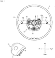
- FIG. 1 is an explanatory diagram of a vehicle steering wheel device according to the present Embodiment illustrating a partially broken steering wheel.
- a horn pad portion covering the airbag module with a horn cover is attached to the steering wheel.
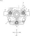
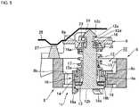
- FIG. 2 is an enlarged view of the main parts of the steering wheel as illustrated in FIG. 1 .
- the steering wheel indicates each direction on the upper and lower left and right with respect to the neutral position at a zero steering angle. Otherwise, the side viewed from the driver's side shall be described as the front side and the opposite side as the back side.
- the steering wheel 1 is installed in the driver seat of the vehicle.
- the boss portion 2 of the steering wheel 1 is connected to a steering shaft passing through the interior of a steering column (not shown).
- the steering wheel 1 transmits the operating force of the driver to the steering gear and the like.
- An airbag module 3 which functions as a driver airbag in an emergency, is mounted in the center of the steering wheel 1. Although this will be described below, the airbag module 3 also functions as a horn switch under normal operation that a driver pushes to cause the horn to sound.
- the driver side of a horn pad portion 4 is covered with a resin horn cover 5 that functions as a design surface.
- the airbag module 3 is provided on the back side of the horn cover 5.
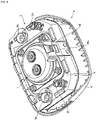
- the airbag module 3 is configured by stowing a folded airbag cushion and an inflator 7 that supplies inflator gas to the airbag cushion inside a box-shaped metal module housing 6 (see FIG. 9 for a state in which the inflator 7 is attached to the module housing 6).
- inflation gas is supplied from the inflator 7 to the airbag cushion.
- the airbag cushion to which the inflation gas is supplied ruptures the horn cover 5 and expands and deploys into the vehicle interior space to restrain and protect the driver.
- the steering wheel 1 includes a central cored bar 8 on which the boss portion 2 is formed, a circular rim portion 9 gripped by the driver, and a spoke portion 10 connecting the central cored bar 8 and the rim portion 9.
- a damper 11 is provided between the steering wheel 1 and the airbag module 3.
- the damper 11 attenuates the vibration transmitted from the steering shaft to the steering wheel 1.
- the airbag module 3 serves as a damper mass of the damper 11 with respect to the steering wheel 1 side.
- the damper 11 is provided between the central cored bar 8 of the steering wheel 1 and the module housing 6 of the airbag module 3.
- a plurality of dampers 11 are arranged around the boss portion 2 of the steering wheel 1. In the illustrated example, three dampers 11 are arranged at appropriate intervals from each other.
- the dampers 11 are provided with reference to the neutral position of the steering wheel 1 with a zero steering angle.
- one damper 11 is arranged on each side of the boss portion 2 in the left-right direction (on the sides of the left and right spoke portions 10), and one damper 11 is provided on the lower side of the boss portion 2 in the center of the steering wheel 1 in the left-right direction.
- the module housing 6 is provided with an inflator 7 facing the central cored bar 8 of the steering wheel 1 in which the damper 11 is arranged.
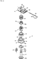
- the damper 11 is made up of a straight shaft-shaped pin 12 that has a connecting tip end part 12a and a base plate part 12b on both ends, a circular insulator 13 encircling the pin 12 and superimposed on the base plate part 12b, a circular rubber 14 encircling the pin 12 and superimposed on the circular insulator 13, a cylindrical insulator 15 with a first spring seat 15a that is superimposed on the rubber 14, provided encircling the pin 12, a collar 16 with a second spring seat 16a, formed in a circular shape encircling the pin 12, provided freely slidable in the axial direction of the pin 12 on the connecting tip end part 12a side and abuts the back side of the module housing 6, a coil-shaped horn spring 17 provided encircling the pin 12 between the first spring seat 15a and second spring seat 16a elastically supporting the module housing 6 via the collar 16,
- the component parts of the damper 11 are made of a synthetic resin molded product except for the metal horn spring 17 and the rubber 14.
- the damper 11 is a substantially cylindrical unit component in which the pin 12 to the grip 19 are integrally assembled so as to simplify the mounting workability to the steering wheel 1 and the connection workability to the airbag module 3.
- a plurality of hooking parts 18a are formed on the holder 18 in a cylindrical shape. These hooking parts 18a support the base plate part 12b from the side opposite of the horn spring 17 side.
- the holder 18 is attached after assembling up to the collar 16 on to the pin 12, and then assembling at least the circular insulator 13, the rubber 14, and the cylindrical insulator 15. For this reason, as illustrated in FIG. 5 , an opening 18b is formed in the holder 18 on the base plate part 12b side in order to insert the assembled portion, and the hooking part 18a is formed so as to be elastically deformable.
- the connecting tip end part 12a of the pin 12 is inserted through the opening 18b of the holder 18, and finally, the base plate part 12b expands the hooking part 18a and is pushed into the holder 18, and the pin 12 is engaged and supported by the elastically restored hooking part 18b [sic].
- the hooking part 18a supports the elastic force of the horn spring 17 acting from the first spring seat 15a of the cylindrical insulator 15 via the rubber 14 and the circular insulator 13.
- the tip 12c of the connecting tip end part 12a is formed in a cone shape. After the horn spring 17 is provided on the pin 12, the collar 16 is pushed into the pin 12 through the cone-shaped tip 12c and mated so that the collar 16 cannot be pulled out.
- the holder 18 having the hooking part 18a and the collar 16 constitute a damper 11 that is integrally assembled and unitized.
- a vibration insulating member is preferably provided between the hooking part 18a and the base plate part 12b so that abnormal noise or undesired vibration does not occur in the pin 12.
- a non-woven fabric or the like can be used as the vibration insulating member, for example.
- This non-woven fabric may be provided by being sandwiched between the hooking part 18a and the base plate part 12b to which the hooking part 18a abuts.
- the holder 18 may be provided with a cover 20 facing the base plate part 12b of the pin 12 as a separate part.
- the opening 18b is closed using a cover 20 by uneven fitting 21 or the like.
- the base plate part 12b is supported by the cover 20 that blocks the opening 18b.
- the cover 20 is preferably formed with a convex portion 20a that is in contact with the base plate part 12b and allows the pin 12 to oscillate.
- the cover 20 is preferably formed with a convex portion 20a that is in contact with the base plate part 12b and allows the pin 12 to oscillate.
- the vibration insulating member may be provided so as to be sandwiched between the cover 20 and the base plate part 12b facing the cover 20.
- the cylindrical insulator 15 surrounding the pin 12 is in point contact with the pin 12 or in line contact with the pin 12 in the axial direction.
- point protrusions and linear protrusions for abutting on the outer surface of the pin 12 are formed. As a result, the damping frequency of the damper 11 is finely adjusted.
- the circular insulator 13 is provided so as to be in close contact with the rubber 14 in the axial direction of the pin 12. As a result, the circular insulator 13 superimposed between the base plate part 12b and the rubber 14 causes the rubber 14 to exhibit the damping performance as set regardless of the mounting accuracy of the holder 18 and the pin 12.
- the holder 18 has a grip 19 on the base plate part 12b side of the pin 12, which is one end portion of the damper 11.
- the grip 19 is engaged to the central cored bar 8 by a rotation operation around the axis of the pin 12 (see arrow r in FIG. 2 ), whereby the damper 11 is secured to the steering wheel 1.
- a mounting hole 8a into which the holder 18 is inserted is formed through the central cored bar 8.
- the mounting hole 8a is formed with a notch 8b through which one of the grips 19 protruding from the holder 18 in pairs is inserted.
- the grip 19 is positioned at the notch 8b, and the holder 18 is rotated by several tens of degrees. Based on the rotation operation, the grip 19 is rotated and moved from the notch 8b position.
- the pair of grips 19 move from the notch 8b position, and grip the central cored bar 8 by sandwiching it from both the front and back surfaces. As a result, the damper 11 is secured to the central cored bar 8.
- the damper 11 secured to the central cored bar 8 is in a state in which the connecting tip end part 12a protrudes from the steering wheel 1 side toward the airbag module 3 side.
- the holder 18 and the grip 19 are integrally formed by resin molding or the like.
- the holder 18 and the grip 19 may be separate parts.
- screw mating may be used.
- the notch 8b may be used as the female thread of the mounting hole 8a, and the grip 19 may be used as the male thread of the holder 18 so as to be engaged by the rotation operation of screw fitting.
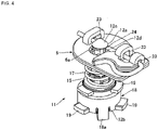
- the central cored bar 8 As illustrated in FIG. 5 , in the central cored bar 8, at least the engaged region 8c to which the grip 19 of the damper 11 is engaged is formed to be thinner than the other peripheral regions. As a result, the central cored bar 8 is provided with a damper installation recess 22 that houses substantially the entire damper 11.
- the installation space for the damper 11 can be secured by utilizing the thickness of the central cored bar 8. If the installation space of the damper 11 is secured, the amount of protrusion of the damper 11 from the steering wheel 1 is adjusted, and the degree of freedom in the mounting design of the airbag module 3 is increased.
- the connecting tip end part 12a of the pin 12, which is the other end of the damper 11, is connected to the module housing 6.
- the connecting tip end part 12a of each damper 11 is inserted into a plurality of insertion holes 6a formed through the module housing 6, respectively.
- the insertion holes 6a are arranged and formed so as to encircle the outer edge of the inflator 7 (see FIG. 9 ). These insertion holes 6a are preferably arranged so as to be close to, preferably very close to, the outer edge of the inflator 7.
- Three insertion holes 6a are formed corresponding to the number of dampers, which is three dampers 11. Further, the insertion hole 6a is arranged so as to face the mounting hole 8a of the central cored bar 8.
- a constricted portion 12d is formed on the connecting tip end part 12a of the pin 12 so as to reduce the diameter.
- the outer diameter of the constricted portion 12d is smaller than the hole diameter of the insertion hole 6a.
- An engaging groove 23 is formed in the module housing 6 of the airbag module 3 by indenting and raising the back surface side toward the front surface side.
- a rod-shaped set spring 24 formed of a metal wire rod is engaged in the engaging groove 23 so as to be supported by the module housing 6.
- the rod-shaped set spring 24 uses an omega spring having a bent portion that abuts on the surface side of the module housing 6 so as not to fall off from the engaging groove 23.
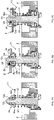
- the set spring 24, which is engaged in the engaging groove 23 and supported on the module housing 6, is arranged so as to cross the insertion hole 6a. As illustrated in FIGS. 6(A) to 6(C) , the set spring 24 is elastically deformed and engaged with the constricted portion 12d of the connecting tip end part 12a which is inserted and goes into the insertion hole 6a. As a result, the connecting tip end part 12a, that is, the damper 11, is connected to the module housing 6, that is, the airbag module 3.
- the insertion hole 6a on the airbag module 3 side is mated toward the connecting tip end part 12a of the damper 11 secured to the steering wheel 1.
- inserting the connecting tip end part 12a into the insertion hole 6a is of course possible.
- the connecting tip end part 12a and the set spring 24 are positioned in the vibration transmission path from the steering wheel 1 to the airbag module 3. Therefore, the connecting tip end part 12a and the set spring 24 may be damaged such as by rubbing against each other when vibration occurs.
- constricted portion 12d of the pin 12 is preferably provided with a cover part to avoid contact with the set spring 24.
- a wear-resistant resin ring 25 is attached to the constricted portion 12d as a separate component.
- a covering layer similar to that of the ring may be formed on the constricted portion 12d by overmolding.
- the set spring 24 may be provided with a wear-resistant cover part to avoid contact with the pin 12.
- the module housing 6 is elastically supported from the steering wheel 1 side by a horn spring 17 incorporated in the damper 1. As illustrated in FIG. 5 , a horn plate 26 is provided on the module housing 6 side.
- the horn plate 26 is provided at a position avoiding the damper 11 so as not to interfere with the damper 11.
- a horn contact 27 is provided on the central cored bar 8 side so as to face the horn plate 26. The horn contact 27 makes the horn sound when coming into contact with the horn plate 26.
- the horn pad portion 4 When the horn pad portion 4 is pressed, the horn spring 17 is shortened. As a result, the horn plate 26 on the airbag module 3 side approaches the central cored bar 8 and comes into contact with the horn contact 27, whereby the horn sounds.
- the horn spring 17 lengthens and is restored. As a result, the horn plate 26 is separated from the horn contact 27, and the sounding of the horn stops.
- a horn mechanism is provided in the steering wheel 1 in a space-saving manner.
- FIG. 1 a state where the damper 11 is attached to the central cored bar 8 is illustrated on the left side where the damper 11 is broken apart, and the state where the damper 11 is connected to the module housing 6 is illustrated on the right side where the damper 11 is broken apart.
- FIG. 2 illustrates a state in which the three dampers 11 are attached to the central cored bar 8.
- the damper 11 as a unit component is assembled in advance.
- the grip 19 is aligned with the notch 8b in each of the mounting holes 8a formed in the central cored bar 8 of the steering wheel 1, and the holder 18 of each damper 11 is inserted.
- the set spring 24 is arranged so as to cross the insertion hole 6a.
- the connecting tip end part 12a of the pin 12 of each damper 11 is inserted into each insertion hole 6a.
- the connecting tip end part 12a having the tip 12c formed in a cone shape elastically deforms and pushes the set spring 24 crossing the insertion hole 6a when covered by the module housing 6 and is inserted into the insertion hole 6a, as illustrated in FIG. 6(B) .
- the tip 12c passes through the set spring 24, as illustrated in FIG. 6(C) , the set spring 24 is elastically restored and the tip enters and engages with the constricted portion 12d inserted into the insertion hole 6a following the tip 12c.
- each damper 11 is connected to the module housing 6. Based on this assembly work, the connection of the plurality of dampers 11 to the airbag module 3 is completed. With the connection work, the horn spring 17 is compressed with a prescribed stroke according to the mounting of the horn pad portion 4.
- the second step of pressing the horn pad portion 4 toward the central cored bar 8 is performed. Following these two steps enables completion of the vehicle steering wheel device according to the present Embodiment.
- the horn plate 26 is arranged so as to face the horn contact 27 on the steering wheel 1 side.
- the completed vehicle steering wheel device is equipped with a function as a front airbag, a function as a horn, and a vibration damping function that exhibits a damping effect comparable to that of the conventional one.
- each damper 11 has a straight pin 12
- the pin 12 is engaged by rotational operation of the axial circumference of the pin 12 to the central cored bar 8 and is provided with a grip 19 for securing the damper 11 on the first end thereof
- a connecting tip end part 12a for connecting with the module housing 6 is provided on the second end thereof
- the module housing 6 is arranged with a plurality of insertion holes 6a encircling the outer edge of the inflator 7 into which the connecting tip end parts 12a are inserted
- the connecting tip end part 12a is provided with a constricted portion 12d with a smaller outer diameter than the hole diameter of the insertion hole 6a
- the connecting tip end part 12a is connected to the module housing 6 via a rod-shaped set spring 24 supported by the module housing 6 that crosses the insertion hole 6a to engage with the
- the insertion holes 6a are arranged so as to be close to, preferably very close to, the outer edge of the inflator 7. Therefore, this is desirable in order to miniaturize the airbag module 3 and the horn pad portion 4 sufficiently.
- the airbag module 3 can be made much smaller than the case where the damper 11 is mounted and fixed to the airbag module 3.
- the installation space of the damper 11 can be secured by utilizing the thickness of the central cored bar 8.
- the amount of protrusion of the damper 11 from the central cored bar 8 can be adjusted, and the degree of freedom in the mounting design of the airbag module 3 can be increased.
- At least one of the pin 12 and the set spring 24 positioned in the vibration transmission path from the steering wheel 1 to the airbag module 3 is provided with a cover part for avoiding contact with the other. As a result, this enables preventing the two from rubbing against each other and causing damage.
- damper 11 is a unit component, the workability of attaching to the steering wheel 1 and the workability of connecting to the airbag module 3 can be simplified.
- the grip 19 is integrally formed with the holder 18, the assemble-ability of the damper 11 can be facilitated.
- the holder 18 includes a cover 20 facing the base plate part 12b of the pin 12, and the cover 20 is formed with a convex portion 20a that is in contact with the base plate part 12b and allows the pin 12 to oscillate.
- the pin 12 can be supported by the convex portion 20a in a manner allowing oscillation, and the flexibility when connecting the connecting tip end part 12a to the module housing 6 can be improved.
- a horn plate 26 is provided on the module housing 6 side elastically supported by the horn spring 17.
- a horn contact 27 that contacts the horn plate 26 and causes the horn to sound is provided on the central cored bar 8 side.
- the horn spring 17 is incorporated in the damper 11. As a result, the steering wheel 1 can be provided with a horn mechanism in a space-saving manner.
- the damping frequency of the damper 11 can be finely adjusted.
- the circular insulator 13 is in close contact with the rubber 14. Therefore, the circular insulator 13 superimposed between the base plate part 12b and the rubber 14 can make the rubber 14 exhibit the damping performance as set regardless of the mounting accuracy of the holder 18 and the pin 12.
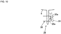
- FIG. 8 to FIG. 10 illustrate modified examples of the above Embodiment.
- three dampers 11 are provided.
- two dampers 11 are arranged on both sides of the boss portion 2 in the left-right direction with reference to the neutral position of the steering wheel 1 at zero steering angle.
- a plate-shaped damper 28 is provided on the lower side of the steering wheel 1 in the center in the left-right direction in place of the remaining one damper 11.
- the plate-shaped damper 28 is provided in parallel with the damper 11 and functions as an engaging mechanism that engages the central cored bar 8 and the module housing 6 so as to be relatively displaceable.
- the plate-shaped damper 28 is made of a resin-coated metal or synthetic resin and is formed as an elastically deformable plate spring.
- the relative displacement specifically refers to a change in the separation distance between the steering wheel 1 and the airbag module 3 due to the vibration of the steering wheel 1 and damping by the damper 11.
- the engaging mechanism is adapted to tolerate this variation in distance.
- Two coil springs 29 are arranged on the left and right sides of the plate-shaped damper 28. A first end of these coil springs 29 is attached to the module housing 6, and a second end is elastically in contact with the central cored bar 8 to support the periphery of the plate-shaped damper 28.
- the plate-shaped damper 28 transmits vibration from the steering wheel 1 to the airbag module 3 by the elastic action thereof.
- the plate-shaped damper 28 cooperates with the airbag module 3 that serves as a damper mass, and dampens the vibration of the steering wheel 1 by means of the elastic action due to plate bending.
- a first end of the plate-shaped damper 28 is joined to the module housing 6, and a second end is formed with an engagement opening 28a that is engaged with a hook 30 projecting from the central cored bar 8.
- the hook 30 has a tapered surface 30a that guides the engagement of the engagement opening 28a. As the plate-shaped damper 28 gets over the tapered surface 30a, the engagement opening 28a is engaged with the hook 30.
- the plate-shaped damper 28 engages the steering wheel 1 and the airbag module 3 in a relatively displaceable manner by allowing the hook 30 to move within the engagement opening 28a.
- the airbag module 3 and the steering wheel 1 are connected at three points by a plate-shaped damper 28 which is an engaging mechanism in addition to the two dampers 11.
- the plate-shaped damper 28 is thinner and smaller than the above-mentioned cylindrical damper 11, the size of the module housing 6 required for assembly can be further reduced as compared with the Embodiment described above, and therefore, the airbag module 3 can be further miniaturized.
- the vehicle steering wheel device described above is a preferred example of the present invention, and other Embodiments can also be implemented or carried out by various methods.
- the invention is not restricted to the shapes, sizes, configurational dispositions, and the like of the parts illustrated in detail in the accompanying drawings.
- the expressions and terms used in the specification of the application are used for providing a description, without limiting the invention thereto, unless specifically described otherwise.
Landscapes
- Engineering & Computer Science (AREA)
- Mechanical Engineering (AREA)
- General Engineering & Computer Science (AREA)
- Chemical & Material Sciences (AREA)
- Combustion & Propulsion (AREA)
- Transportation (AREA)
- Acoustics & Sound (AREA)
- Aviation & Aerospace Engineering (AREA)
- Physics & Mathematics (AREA)
- Air Bags (AREA)
- Steering Controls (AREA)
- Steering-Linkage Mechanisms And Four-Wheel Steering (AREA)
- Vibration Prevention Devices (AREA)
Applications Claiming Priority (2)
| Application Number | Priority Date | Filing Date | Title |
|---|---|---|---|
| JP2020005080 | 2020-01-16 | ||
| PCT/JP2020/047624 WO2021145150A1 (ja) | 2020-01-16 | 2020-12-21 | 車両のステアリングホイール装置 |
Publications (2)
| Publication Number | Publication Date |
|---|---|
| EP4091908A1 true EP4091908A1 (de) | 2022-11-23 |
| EP4091908A4 EP4091908A4 (de) | 2024-03-13 |
Family
ID=76863699
Family Applications (1)
| Application Number | Title | Priority Date | Filing Date |
|---|---|---|---|
| EP20913940.1A Pending EP4091908A4 (de) | 2020-01-16 | 2020-12-21 | Lenkradvorrichtung für fahrzeuge |
Country Status (5)
| Country | Link |
|---|---|
| US (1) | US20230174152A1 (de) |
| EP (1) | EP4091908A4 (de) |
| JP (1) | JP7271728B2 (de) |
| CN (1) | CN114845926B (de) |
| WO (1) | WO2021145150A1 (de) |
Families Citing this family (5)
| Publication number | Priority date | Publication date | Assignee | Title |
|---|---|---|---|---|
| JP7347149B2 (ja) * | 2019-11-18 | 2023-09-20 | Joyson Safety Systems Japan合同会社 | ステアリングホイール |
| JP7410308B2 (ja) * | 2020-08-28 | 2024-01-09 | オートリブ ディベロップメント エービー | 車両のステアリングホイール装置 |
| US12194939B2 (en) | 2021-01-20 | 2025-01-14 | Autoliv Development Ab | Driver seat airbag device |
| EP4559780A4 (de) * | 2022-08-25 | 2026-01-07 | Autoliv Dev | Struktur zur befestigung eines airbagmoduls an einem lenkrad |
| CN117227825B (zh) * | 2023-10-30 | 2025-09-05 | 锦州锦恒汽车安全系统股份有限公司 | 方向盘用气囊模块总成 |
Family Cites Families (29)
| Publication number | Priority date | Publication date | Assignee | Title |
|---|---|---|---|---|
| JP3942338B2 (ja) * | 2000-05-12 | 2007-07-11 | 豊田合成株式会社 | ステアリングホイールのホーンスイッチ |
| DE20017527U1 (de) * | 2000-10-12 | 2001-02-22 | TRW Automotive Safety Systems GmbH & Co. KG, 63743 Aschaffenburg | Fahrzeuglenkrad |
| JP4023098B2 (ja) * | 2000-11-29 | 2007-12-19 | 豊田合成株式会社 | ステアリングホイールのホーンスイッチ |
| DE202006016948U1 (de) * | 2006-11-06 | 2007-02-01 | Trw Automotive Safety Systems Gmbh | Einstellbare Vorrichtung zur Dämpfung von Schwingungen in einem Lenkrad oder Gassackmodul |
| JP5153526B2 (ja) * | 2008-02-01 | 2013-02-27 | 本田技研工業株式会社 | ステアリングホイールの振動低減構造 |
| CN103298680B (zh) * | 2010-11-19 | 2016-01-06 | 本田技研工业株式会社 | 方向盘 |
| JP5836685B2 (ja) * | 2011-07-27 | 2015-12-24 | タカタ株式会社 | ステアリングホイール |
| JP2013071626A (ja) * | 2011-09-28 | 2013-04-22 | Toyoda Gosei Co Ltd | ステアリングホイールの制振構造 |
| JP5989449B2 (ja) * | 2012-08-06 | 2016-09-07 | タカタ株式会社 | ステアリングホイール |
| JP2015071402A (ja) * | 2013-09-04 | 2015-04-16 | オートリブ ディベロップメント エービー | ステアリングホイール装置 |
| US9731747B2 (en) * | 2014-02-21 | 2017-08-15 | Honda Motor Co., Ltd. | Steering wheel structure |
| JP2015160438A (ja) * | 2014-02-25 | 2015-09-07 | オートリブ ディベロップメント エービー | ステアリングホイール装置 |
| JP6164175B2 (ja) * | 2014-07-30 | 2017-07-19 | 豊田合成株式会社 | ステアリングホイール |
| JP2016199183A (ja) * | 2015-04-13 | 2016-12-01 | タカタ株式会社 | ステアリングホイール |
| JP6443278B2 (ja) * | 2015-09-10 | 2018-12-26 | 豊田合成株式会社 | ステアリングホイール |
| JP2017159696A (ja) * | 2016-03-07 | 2017-09-14 | タカタ株式会社 | エアバッグモジュール用ダンパユニット及びステアリングホイール |
| JP6673752B2 (ja) * | 2016-06-08 | 2020-03-25 | 本田技研工業株式会社 | ハンドル |
| US10351089B2 (en) * | 2016-07-29 | 2019-07-16 | Toyoda Gosei Co., Ltd. | Support structure for airbag apparatus |
| DE102016124530A1 (de) * | 2016-12-15 | 2018-06-21 | Trw Automotive Safety Systems Gmbh | Kopplungsvorrichtung zur schwingfähigen Befestigung eines Gassackmoduls an einem Fahrzeuglenkrad |
| JP6835633B2 (ja) * | 2017-03-10 | 2021-02-24 | 芦森工業株式会社 | ステアリングハンドル構造 |
| JP6817872B2 (ja) * | 2017-04-07 | 2021-01-20 | 芦森工業株式会社 | エアバッグ装置の取付構造 |
| JP6809427B2 (ja) * | 2017-09-28 | 2021-01-06 | 豊田合成株式会社 | ステアリングホイール |
| WO2019142654A1 (ja) * | 2018-01-19 | 2019-07-25 | オートリブ ディベロップメント エービー | ステアリングホイール |
| JP7015194B2 (ja) * | 2018-03-19 | 2022-02-02 | 芦森工業株式会社 | ステアリングホイール |
| JP6885366B2 (ja) * | 2018-03-29 | 2021-06-16 | 豊田合成株式会社 | エアバッグ装置 |
| JP7094763B2 (ja) * | 2018-04-26 | 2022-07-04 | Joyson Safety Systems Japan株式会社 | ステアリングホイール |
| FR3085909B1 (fr) * | 2018-09-13 | 2021-05-28 | Autoliv Dev | Volant de vehicule comprenant un dispositif de commande d'avertisseur sonore |
| KR102693552B1 (ko) * | 2019-04-11 | 2024-08-08 | 현대모비스 주식회사 | 운전석 에어백장치 |
| JP7410821B2 (ja) * | 2020-08-19 | 2024-01-10 | Joyson Safety Systems Japan合同会社 | ステアリングホイール |
-
2020
- 2020-12-21 JP JP2021570704A patent/JP7271728B2/ja active Active
- 2020-12-21 EP EP20913940.1A patent/EP4091908A4/de active Pending
- 2020-12-21 US US17/758,914 patent/US20230174152A1/en active Pending
- 2020-12-21 CN CN202080089024.2A patent/CN114845926B/zh active Active
- 2020-12-21 WO PCT/JP2020/047624 patent/WO2021145150A1/ja not_active Ceased
Also Published As
| Publication number | Publication date |
|---|---|
| CN114845926A (zh) | 2022-08-02 |
| CN114845926B (zh) | 2023-10-13 |
| JPWO2021145150A1 (de) | 2021-07-22 |
| US20230174152A1 (en) | 2023-06-08 |
| WO2021145150A1 (ja) | 2021-07-22 |
| EP4091908A4 (de) | 2024-03-13 |
| JP7271728B2 (ja) | 2023-05-11 |
Similar Documents
| Publication | Publication Date | Title |
|---|---|---|
| EP4091908A1 (de) | Lenkradvorrichtung für fahrzeuge | |
| JP6968279B2 (ja) | ステアリングホイールにおけるダンパユニットの取付固定構造及びステアリングホイール | |
| US11034374B2 (en) | Steering wheel | |
| EP2085290B1 (de) | Vorrichtung zur Dämpfung von Schwingungen in einem Lenkrad | |
| KR102610029B1 (ko) | 스티어링 휠 | |
| CN110962911B (zh) | 车辆方向盘所具备的减振器结构 | |
| US11529921B2 (en) | Steering wheel | |
| CN104925016A (zh) | 方向盘 | |
| JP6673752B2 (ja) | ハンドル | |
| US12522275B2 (en) | Steering wheel and method of manufacturing same | |
| JP2017218034A (ja) | ハンドル | |
| JP7410308B2 (ja) | 車両のステアリングホイール装置 | |
| US12252089B2 (en) | Steering wheel | |
| EP4559780A1 (de) | Struktur zur befestigung eines airbagmoduls an einem lenkrad | |
| US20260014952A1 (en) | Airbag device provided to steering wheel | |
| JP7286218B2 (ja) | ステアリングホイールにおけるダンパユニットの取付固定構造及び車両のステアリングホイール装置 | |
| EP4566914A1 (de) | Fahrzeuglenkradvorrichtung |
Legal Events
| Date | Code | Title | Description |
|---|---|---|---|
| STAA | Information on the status of an ep patent application or granted ep patent |
Free format text: STATUS: THE INTERNATIONAL PUBLICATION HAS BEEN MADE |
|
| PUAI | Public reference made under article 153(3) epc to a published international application that has entered the european phase |
Free format text: ORIGINAL CODE: 0009012 |
|
| STAA | Information on the status of an ep patent application or granted ep patent |
Free format text: STATUS: REQUEST FOR EXAMINATION WAS MADE |
|
| 17P | Request for examination filed |
Effective date: 20220802 |
|
| AK | Designated contracting states |
Kind code of ref document: A1 Designated state(s): AL AT BE BG CH CY CZ DE DK EE ES FI FR GB GR HR HU IE IS IT LI LT LU LV MC MK MT NL NO PL PT RO RS SE SI SK SM TR |
|
| DAV | Request for validation of the european patent (deleted) | ||
| DAX | Request for extension of the european patent (deleted) | ||
| A4 | Supplementary search report drawn up and despatched |
Effective date: 20240208 |
|
| RIC1 | Information provided on ipc code assigned before grant |
Ipc: F16F 15/04 20060101ALI20240202BHEP Ipc: B62D 1/10 20060101ALI20240202BHEP Ipc: B60R 21/203 20060101ALI20240202BHEP Ipc: B62D 7/22 20060101AFI20240202BHEP |
|
| GRAP | Despatch of communication of intention to grant a patent |
Free format text: ORIGINAL CODE: EPIDOSNIGR1 |
|
| STAA | Information on the status of an ep patent application or granted ep patent |
Free format text: STATUS: GRANT OF PATENT IS INTENDED |