EP4091875A1 - Armlehne - Google Patents
Armlehne Download PDFInfo
- Publication number
- EP4091875A1 EP4091875A1 EP22173312.4A EP22173312A EP4091875A1 EP 4091875 A1 EP4091875 A1 EP 4091875A1 EP 22173312 A EP22173312 A EP 22173312A EP 4091875 A1 EP4091875 A1 EP 4091875A1
- Authority
- EP
- European Patent Office
- Prior art keywords
- armrest
- gear
- lateral
- pivoting
- drive
- Prior art date
- Legal status (The legal status is an assumption and is not a legal conclusion. Google has not performed a legal analysis and makes no representation as to the accuracy of the status listed.)
- Granted
Links
Images






Classifications
-
- B—PERFORMING OPERATIONS; TRANSPORTING
- B60—VEHICLES IN GENERAL
- B60N—SEATS SPECIALLY ADAPTED FOR VEHICLES; VEHICLE PASSENGER ACCOMMODATION NOT OTHERWISE PROVIDED FOR
- B60N2/00—Seats specially adapted for vehicles; Arrangement or mounting of seats in vehicles
- B60N2/75—Arm-rests
- B60N2/763—Arm-rests adjustable
- B60N2/767—Angle adjustment
-
- B—PERFORMING OPERATIONS; TRANSPORTING
- B60—VEHICLES IN GENERAL
- B60N—SEATS SPECIALLY ADAPTED FOR VEHICLES; VEHICLE PASSENGER ACCOMMODATION NOT OTHERWISE PROVIDED FOR
- B60N2/00—Seats specially adapted for vehicles; Arrangement or mounting of seats in vehicles
- B60N2/02—Seats specially adapted for vehicles; Arrangement or mounting of seats in vehicles the seat or part thereof being movable, e.g. adjustable
- B60N2/0224—Non-manual adjustments, e.g. with electrical operation
- B60N2/02246—Electric motors therefor
-
- B—PERFORMING OPERATIONS; TRANSPORTING
- B60—VEHICLES IN GENERAL
- B60N—SEATS SPECIALLY ADAPTED FOR VEHICLES; VEHICLE PASSENGER ACCOMMODATION NOT OTHERWISE PROVIDED FOR
- B60N2/00—Seats specially adapted for vehicles; Arrangement or mounting of seats in vehicles
- B60N2/75—Arm-rests
- B60N2/753—Arm-rests movable to an inoperative position
-
- B—PERFORMING OPERATIONS; TRANSPORTING
- B60—VEHICLES IN GENERAL
- B60N—SEATS SPECIALLY ADAPTED FOR VEHICLES; VEHICLE PASSENGER ACCOMMODATION NOT OTHERWISE PROVIDED FOR
- B60N2/00—Seats specially adapted for vehicles; Arrangement or mounting of seats in vehicles
- B60N2/75—Arm-rests
- B60N2/763—Arm-rests adjustable
- B60N2/77—Height adjustment
-
- B—PERFORMING OPERATIONS; TRANSPORTING
- B60—VEHICLES IN GENERAL
- B60N—SEATS SPECIALLY ADAPTED FOR VEHICLES; VEHICLE PASSENGER ACCOMMODATION NOT OTHERWISE PROVIDED FOR
- B60N2/00—Seats specially adapted for vehicles; Arrangement or mounting of seats in vehicles
- B60N2/75—Arm-rests
- B60N2/763—Arm-rests adjustable
- B60N2/777—Transversal adjustment
Definitions
- the invention relates to an armrest of a seat, in particular a vehicle seat.
- a vehicle can be a land, air or water vehicle.
- Such an armrest is from the 10 2019 000 119 A1 known.
- the armrest of this armrest has a seat-fixed guide tube in which an armrest-fixed axle is guided and driven in such a way that the axle can first be removed laterally from the seat and then pivoted into a use position.
- a link is provided in the guide tube, which only allows pivoting when the armrest has been removed from the seat.
- the lateral movement is provided by a motor which charges a spring as the armrest moves to the removed position. The reverse movement is powered by the spring.
- the armrest includes an armrest that is moveable relative to the seat with a lateral mechanism between a first proximal position and a third distal position.
- the armrest is pivoted via a second intermediate position between the proximal position and the distal position.
- the armrest In the proximal position, the armrest is accommodated, for example, in a recess in the backrest of the seat and/or, for example, parallel to a sagittal plane in direction x behind the seat, or to the side or behind an occupant contact surface seat arranged.
- the armrest In the distal position, the armrest is spaced apart, for example from the backrest, laterally in direction y, parallel to a transverse plane, such that the armrest can be pivoted.
- sagittal plane, transverse plane, proximal and distal are terms that describe planes of a seat occupant's body, but are also applied here in the same way to the vehicle seat itself, in which the occupant is seated in the intended sitting position.
- the armrest is pivotable between a primary position and a tertiary position.
- the armrest pivots through a secondary position that is an intermediate position between the primary position and the secondary position.
- a longitudinal axis of the armrest is arranged, for example, in the area of a vertical, but the angle can deviate from this.
- the deviation can be up to 25°, in particular 0° to 15°.
- the primary position is a roughly vertical position.
- the longitudinal axis of the armrest is arranged, for example, in the area of a horizontal line, but can deviate from this by up to 25%, in particular 0° to 15°.
- the tertiary position is an approximately horizontal position.
- the lateral mechanism includes an articulated connection with a first part that can be fastened to the seat and a second part that is assigned to the armrest.
- the articulated connection forms at least one linkage, for example with the first part and with the second part.
- the second part With the linkage, the second part, which is connected to the armrest, can be moved relative to the first part on a coupling curve between a first position and a third position.
- the movement of the second part takes place, for example, in a horizontal xy plane without significant vertical movement component in direction z.
- the first part is pivotally connected to at least one link, which link is also pivotally connected to the second part.
- the articulation comprises a four-bar linkage.
- the armrest is guided on a defined path of movement, which is formed by a coupling curve specified by the four-bar linkage.
- the four-bar linkage comprises, for example, at least one first link and at least one second link, each link forming a pivot joint with the first part and also forming a pivot joint with the second part.
- the four-bar linkage can be designed as a multiple four-bar linkage with a plurality of first links and a plurality of second links or any combination thereof.
- the four-bar linkage has two first links and two second links.
- the two first links can be part of a first bracket and the two second links can be part of a second bracket.
- the links of the four-bar linkage pivot about 90° when moving between the first and third positions.
- the advantages of moving the lateral mechanism by means of a linkage are, for example, that the armrest has stable guidance and favorable movement characteristics.
- the pivoting mechanism comprises, for example, the second part and a pivoting part that is fixed to the armrest, the second part and the pivoting part forming a pivot joint with one another.
- an element fastened to it can also be part of the pivoting mechanism.
- the second part and the pivot part define a pivot axis about which the armrest is pivotable between the first position and the second position.
- the movement of the lateral mechanism and/or the pivoting mechanism can, for example, be carried out manually, i. i.e. a drive is not necessary.
- the lateral mechanism and/or the pivoting mechanism have a drive, e.g. at least in a partial area of their movement. That is, the lateral mechanism and/or the pivoting mechanism have a drive, for example, in the entire range of their movement. Alternatively, the lateral mechanism and/or the pivoting mechanism only have a drive in a partial area.
- a drive device can have a lateral gear for moving the lateral mechanism and/or a swivel gear for moving the swivel mechanism.
- the lateral mechanism and the pivoting mechanism are coupled via a gear and move synchronously.
- the gearbox is driven by only one drive.
- the translation of the respective gear can be e.g. 1:1, but can alternatively also have other translations.
- the translation can be provided, for example, to be able to dose the movement better and to influence the forces.
- the speed of a drive motor which generally rotates at a high speed, can be increased in such a way that a desired movement speed is obtained for the lateral movement and/or for the pivoting movement.
- the range of motion of the respective mechanism ie the lateral mechanism and the swivel mechanism
- the lateral mechanics are driven over the entire range of motion.
- the translation of the pivoting gear it can then be determined, for example, that the pivoting mechanism is only driven over part of the movement, for example 45°.
- the swivel mechanism z. B. contain an energy storage.
- the armrest is moved to the tertiary position by a potential energy.
- an energy store supports the movement to the primary position.
- the lateral mechanism is fully driven and the pivoting mechanism is driven in at least a partial area.
- the pivoting mechanism is driven in at least a partial area.
- the lateral gear and/or the pivoting gear comprise, for example, at least one drive, for example in the form of a motor and/or an energy store for moving the respective mechanism, ie the lateral mechanism and/or the pivoting mechanism.
- Energy storage within the meaning of the invention can also be, for example, potential energy or dynamic energy of an element, for example the armrest.
- only one motor or, for example, one motor each can be present as a drive for the lateral gear and the swivel gear.
- the mechanism is moved by an electric motor.
- the electric motor can, for example, drive a rotating part such as a spindle nut or a spindle or a gear train.
- the mechanism can also be driven by means of an energy store, for example by means of a spring.
- the relative movement of a first link of the four-bar linkage relative to a second link of the four-bar linkage or a part in a defined position relative to the second link is used, according to a special embodiment, to drive the pivoting movement of the armrest.
- the relative movement of the links is used to move a first toothing mounted on the first link of the four-bar linkage relative to a second toothing that is fixedly or movably mounted on a second link of the four-bar linkage.
- the first toothing is formed by a first gear wheel and the second toothing by a second gear wheel, which is pivotably mounted on the second link of the four-bar linkage.
- the second gear is connected to the armrest.
- At least one of the drives of the lateral gear and swivel gear includes, for example, a spindle which is in engagement with a spindle nut, the spindle or the spindle nut being drivable.
- the lateral mechanics in particular the four-bar linkage, can be adjusted between the two end positions.
- At least one of the drives of the lateral gear and swivel gear comprises, for example, at least two gear wheels that mesh with one another.
- one gear wheel is associated with the armrest and the other gear wheel is associated with the lateral gear or the vehicle, in particular the vehicle seat.
- the swing gear has a pair of gears.
- One of the links of the linkage is driven directly on at least one swivel joint.
- the pivot axis is driven directly.
- At least one of the drives of the lateral gear and swivel gear can be detachably coupled to the respective mechanism, i.e. the lateral mechanism or the swivel mechanism, e.g. by means of at least one coupling device in the broadest sense.
- a clutch device is to be understood, for example, as both separable clutch elements and a control structure with two elements, one element entraining the other only after a certain range of freewheeling.
- the mechanical transmission of the control structure from a first element to a second element takes place only after a specific range of movement of the first element.
- the word detachable should be understood to mean both detachable and detachable. This means that the drive can be separated from the respective mechanics in such a way that the drive can move independently.
- the armrest it is possible for the armrest to be moved partially or completely manually between the first position and the third position and/or between the primary and the tertiary position, bypassing the drive device.
- the lateral gear and the pivoting gear can be driven at the same time, although this does not have to lead to a pivoting movement of the armrest in all areas of the movement.
- the drive is activated, with the lateral gear and the swivel gear being moved. Nevertheless, initially only the lateral mechanism is moved, for example.
- the movement of the pivoting mechanism is, for example, due to interacting Coupling structures of the swivel gear only when the armrest is laterally spaced far enough from the backrest that the backrest is no longer in the pivot path of the armrest.
- the armrest is swiveled upwards by approx. 45 degrees from an approximately horizontal tertiary position when the swivel gear is in the disengaged state.
- the movement into the approximately vertical primary position is then taken over by the swivel gear after it has been engaged, for example.
- the movement can be carried out manually in an ergonomically tolerable range, which is e.g. faster.
- the movement then takes place by means of the drive.
- the armrest has a locking device with which the lateral mechanism and/or the pivoting mechanism can be locked in at least one position.
- the lateral mechanism and/or the pivoting mechanism can be locked in at least one end position.
- the lateral mechanism can be locked in the first position and the third position, for example.
- the swivel mechanism can be locked in the primary position and the tertiary position.
- a vehicle seat as a whole is denoted by the reference numeral 10 in the figures.
- the vehicle seat 10 includes according to 1 a seat area 11 with a seat surface 12 and a backrest 13 with a contact surface 14.
- the contact surface 14 points in the direction x1, parallel to a sagittal plane of a seat occupant.
- the x2 direction is opposite to the x1 direction.
- the vehicle seat 10 includes an armrest 20 constructed in accordance with the features of the invention.
- the armrest 20 comprises an armrest 15 which comprises an end region 41 close to the fastening and a free end region 42 as well as an armrest surface 43 .
- the armrest 15 is in the directions y1 and y2 between one in the Figures 1 to 4 illustrated proximal first position and one in the Figures 19 to 36 illustrated distal third position movable.
- the lateral movement of the armrest 15 takes place in the Figures 11 to 18b illustrated second position, in which the lateral mechanism 27 is in an intermediate position between the first position and the second position.
- the armrest 15 In the first position, the armrest 15 is proximal relative to the backrest 13, ie, close to the backrest 13, with respect to directions y1 and y2, and in the third position, the armrest 15 is distal relative to the backrest 13, ie, in direction y2 of FIG the backrest 13 removed, arranged.
- the armrest 15 can be swiveled in the directions of rotation u1 and u2 between a primary position (see Figures 1 to 18b ), and a tertiary position pivotable about a pivot axis a, which is shown in the Figures 27 to 36 is shown.
- An intermediate position between the primary position and the tertiary position is referred to as the secondary position and in the Figures 19 to 26b shown.
- the armrest 15 can be pivoted upwards in the reverse direction u2 between the tertiary and primary positions of the pivot mechanism 28 and moved from the third position to the first position of the lateral mechanism 27 .
- the armrest 15 in the first position is partially behind an occupant contact surface in the x-direction the backrest 13 is located, so that a pivoting of the armrest 15 in the direction u1 according to 2 would not be possible because the backrest 13 would be in the path of movement of the armrest 15.
- the armrest 15 protrudes z. B. laterally, ie with respect to the direction y2, not or only slightly beyond the dimensions of the seat area 11 and the backrest 13 extending in the direction y1 and y2.
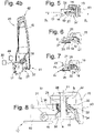
- FIG 4a and 4b the armrest 20 is shown separately without the other components of the vehicle seat.
- the lateral mechanism 27 is provided for the lateral movement in the directions y1 and y2 between the first position and the third position of the armrest 15 and is explained in more detail below.
- a first part 16 has fastening means 17 in the form of a flange (see Figures 5 to 9a) with which it is firmly fixed to the structure of the backrest 13.
- a second part 18 is connected to the armrest 15 .
- the first part 16 and the second part 18 are connected to one another with an articulated connection 37 .
- the articulated connection 37 is designed as a linkage, in particular, as in the present embodiment, as a four-bar linkage.
- the movement of the second part takes place, for example, in a horizontal x-y plane without a significant vertical z component of the movement.
- the joint connection 37 comprises a link 19 and a link 21.
- Each of the links 19 and 21 forms a swivel joint with the first part 16 and with the second part 18.
- the first part 16, the second part 18 and the links 19 and 21 form a four-bar linkage 23.
- the armrest 15 can therefore be moved by means of the four-bar linkage 23 on a coupling curve between the first position and the third position.
- the first position and the third position of the lateral Mechanisms of movement 27 are fixed in the form of stops, not shown.
- the second part 18 is also a support for part of the pivot mechanism 28. It forms a pivot joint S with a pivot structure 22 to which the armrest 15 is firmly connected. With the pivot joint S, the armrest 15 is about the pivot axis a, which is physical axis 31 fixedly connected to the second part 18 is pivotally supported on the second part 18 between the primary position and the tertiary position.
- the primary position and the tertiary position of the pivot mechanism 28 are defined with stops, not shown.
- the armrest 15 could be moved manually into defined positions and locked there. That is, lateral movement and the pivoting movement could be carried out manually.
- the lateral movement and/or the pivoting movement to take place in a driven manner in at least a partial area of the movement.
- the movement of the armrest 15 is semi-automatic. Movement between the first position and the third position is fully powered with respect to both directions of movement.
- the armrest 10 has a drive device with a motor and a lateral gear 35 .
- the movement between the primary position and a secondary position (see 19 ) is powered about through an angle of about 45° relative to the primary position.
- the armrest 10 has a swivel gear 36 for this purpose. Movement between the secondary and tertiary positions is automatic and driven by the potential energy of the armrest 15.
- the lateral mechanism and the pivoting mechanism are driven by only one drive 26, e.g. an electric motor.
- the lateral mechanism may be driven by a first drive and for the pivoting mechanism to be driven by a second drive.
- the lateral gear 35 comprises a spindle 24 which is in engagement with a spindle nut 25 (see, e.g 7 ) and pivotally connected to the first part.
- the spindle nut 25 is fixed to one of the handlebars 19 or 21, here with the handlebar 21 connected.
- the spindle 24 can be rotated about its longitudinal central axis b by means of a motor 26 . In this way, the armrest 15 can be adjusted between the first and the third position of the lateral mechanism 27 by means of the lateral gear 35, in the present case the spindle 24 and the spindle nut 25.
- the armrest is moved so far in direction y1 that the backrest 13 does not move in the pivoting path between the primary position and the tertiary position of the armrest 15 located.
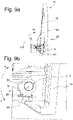
- the swivel gear 36 for the movement between the primary and the secondary position comprises a first toothing 29, here in the form of a first gear wheel (see FIG Figures 9a and 9b ), which is arranged on the handlebar 21 and immovable is firmly connected to the link 21 and a second toothing 32, here in the form of a rotatably connected to the armrest 15 and relative to the axis 31 in the directions u1 and u2 rotatable second gear.
- the axle 31 is held firmly on the second part 18 .
- the first toothing 29 and the second toothing 32 are formed only by quadrant toothings. Alternatively, however, they could also be designed differently, for example as full-circle toothing.
- the swivel gear 36 and the lateral gear 35 move simultaneously.
- the swivel gear 36 is driven by the relative movement of the coupling gear, i.e. by the relative movement of a part of the lateral mechanism 27 relative to the second gear wheel 32.
- the armrest 10 has a coupling device 34, for example in the 16 and 24 is shown.
- the armrest 15 can be decoupled from the drive mechanism by means of the coupling device 34 so that it can be moved manually.
- the clutch device 34 comprises a first clutch structure 38 connected to the armrest 15 and a second clutch structure 39 firmly connected to the second gear wheel Coupling structure 39 are moved.
- the clutch structures 38 and 39 form control structures, ie the clutch includes a freewheeling area in which the clutch structures 38 and 39 are not engaged and an engagement area in which the clutch structures 38 and 39 are engaged. In other words, in certain relative positions of the first toothing to the second toothing 32 move Coupling structures 38 and 39 engaged. Transmission of movement of the second gear takes place when the clutch structures 38 and 39 are engaged in an engaged position. In a release position, the clutch structures 38 and 39 are disengaged and no transmission takes place.
- the clutch structures 38 and 39 are engaged when the lateral mechanism 27 has moved from the first position to the second position.
- the coupling structures 38 and 39 are in the release position between the first position and the second position of the lateral mechanism 27 .
- the armrest 10 has a control device 30 which interacts with a sensor device 40 (not shown). This has position sensors, not shown.
- the controller 30 controls the motor 26.
- the sensors of the sensor device 40 detect whether the lateral mechanism is in the first or the third position and whether the pivot mechanism 28 is in the primary position or the tertiary position or whether it is from the tertiary position to the secondary position has been moved and has reached the secondary position.
- the control device 30 receives the signal that the armrest 15 should be transferred from the non-use position to a use position.
- the armrest 15 is according to the Figures 1 to 9b shown in the non-use position.
- the drive 26 is then activated by the control device. This moves the spindle nut 25 of the lateral gear 35, so that the lateral mechanism 27 is moved in a first direction of movement of the coupling cam. Due to the Movement of the lateral mechanism also drives the swivel gear 36, so that the teeth 38 and 39 also roll off one another.
- the changes in the relative positions of the multi-joint relative to the second toothing 32 are used as a drive to pivot the armrest 15 .
- the lateral drive is in the position according to 7 and the swivel drive 36 in the position shown in FIG Figure 9b .
- the swivel gear 36 rolls over a certain area without the armrest 15 moving out of the primary position (cf 1 and 10 - 18b ) emotional.
- the clutch structures 38 and 39 are in the engaged position, which is the case in the second position of the lateral mechanism 27 (see Fig Figures 10 to 18b )
- the swivel gear 36 drives the armrest 15 in direction u1 during the further movement.
- the teeth 38 and 39 have the position shown in FIG Figure 18b on.
- the weight loads the armrest 15 in the direction u1.
- the coupling device 34 allows movement in direction u1.
- a rotation damper prevents the armrest 15 from moving unbraked in direction u1 into the tertiary position according to FIG Figures 27 to 36 emotional.
- the lateral gear 35 is in the position according to FIG 23 and the swivel gear 36 in the position according to FIG Figure 26b , ie that the teeth 29 and 32 are located at a second end.
- the armrest 15 is according to the Figures 20 to 26b shown in a 45° position, although, as explained above, it can move independently of the swing gear 36 due to the overrunning portions of the coupling device 34.
- the control device 30 gives a signal to the lateral drive device 27 to stop the drive 26 .
- the upward movement takes place in the opposite direction.
- the armrest 15 is manually moved from the tertiary position to the secondary position while the secondary drive mechanism 36 is still uncoupled by means of the clutch device 34 .
- the coupling structures 38 and 39 reach the engaged position, the coupling structure 39 is latched to the coupling structure 38 - e.g. by a driving pin (not shown).
- Reaching the secondary position of the armrest 15 is communicated by the sensor device 40 to the control device 30, whereupon the latter causes the drive 26 to move in the reverse direction, such that the armrest 15 pivots in direction u2.
- the armrest 15 After a pivoting radius of about 45°, the armrest 15 is again in the primary position and the lateral mechanism 27 has reached the second position. The latching of the coupling structures 38 and 39 is now released.
- the coupling device 34 allows additional relative movement of the coupling structures 38 and 39 without moving the armrest 15 from the primary position. The further movement of the drive, i. H. of the motor 26, so has no influence on the pivoting position of the armrest 15, because this is then back in the freewheeling area.
- the lateral mechanism 27 can therefore be moved from the second to the first position. As soon as the first position has been reached, the control device 30 stops the drive.
Landscapes
- Engineering & Computer Science (AREA)
- Aviation & Aerospace Engineering (AREA)
- Transportation (AREA)
- Mechanical Engineering (AREA)
- Seats For Vehicles (AREA)
Abstract
Description
- Die Erfindung betrifft eine Armlehne eines Sitzes, insbesondere eines Fahrzeugsitzes. Ein Fahrzeug kann im Sinne dieser Erfindung ein Land-, Luft- oder Wasserfahrzeug sein.
- Eine solche Armlehne ist aus der
10 2019 000 119 A1 - Es war Aufgabe der Erfindung eine Armlehne zu schaffen, die einen geringen Bauraum erfordert und die mit einem relativ geringen Fertigungsaufwand herstellbar ist.
- Die Aufgabe wurde gelöst durch eine Armlehne mit den Merkmalen des Anspruchs 1.
- Die Armlehne umfasst eine Armauflage, die relativ zu dem Sitz mit einer Lateralmechanik zwischen einer ersten proximalen Position und einer dritten distalen Position bewegbar ist. Dabei wird die Armauflage über eine zweite Zwischenposition zwischen der proximalen Position und der distalen Position geschwenkt. In der proximalen Position ist die Armauflage z.B. in einer Aussparung der Rückenlehne des Sitzes aufgenommen und / oder z.B. parallel zu einer Sagittalebene in Richtung x hinter dem Sitz, oder seitlich oder hinter einer Insassen-Anlagefläche des Sitzes angeordnet. In der distalen Position ist die Armauflage z.B. von der Rückenlehne derart lateral in Richtung y, parallel zu einer Transversalebene beabstandet, dass ein Schwenken der Armauflage möglich ist.
- Die Worte Sagittalebene, Transversalebene, proximal und distal sind Begriffe, die Ebenen des Körpers eines Sitzinsassen beschreiben, hier aber in gleicher Weise aber auch auf den Fahrzeugsitz an sich angewendet werden, in welchem der Insasse in der vorgesehenen Sitzhaltung Platz genommen hat.
- Mit einer Schwenkmechanik der Armlehne ist die Armauflage zwischen einer primären Position und einer tertiären Position schwenkbar. Die Armlehne wird über eine sekundäre Position hinweg geschwenkt, die eine Zwischenposition zwischen der primären Position und der sekundären Position ist. In der primären Position ist eine Längsachse der Armauflage z.B. im Bereich einer Vertikalen angeordnet, der Winkel kann aber davon abweichen. Die Abweichung kann bis zu 25° betragen, insbesondere 0° bis 15°. Die primäre Position ist z.B. eine etwa vertikale Position. In der tertiären Position ist die Längsachse der Armauflage z.B. im Bereich einer Horizontalen angeordnet, kann aber davon abweichen, bis zu 25%, insbesondere 0° bis 15°. Die tertiäre Position ist z.B. eine etwa horizontale Position.
- Die Lateralmechanik umfasst eine Gelenkverbindung mit einem an dem Sitz befestigbaren ersten Teil und einem der Armauflage zugeordneten zweiten Teil. Die Gelenkverbindung bildet z.B. mit dem ersten Teil sowie mit dem zweiten Teil wenigstens ein Koppelgetriebe. Mit dem Koppelgetriebe ist das mit der Armlehne verbundene zweite Teil relativ zu dem ersten Teil auf einer Koppelkurve zwischen einer ersten Position und einer dritten Position bewegbar. Die Bewegung des zweiten Teils erfolgt z.B. in einer horizontalen x-y-Ebene ohne wesentlichen vertikalen Bewegungsanteil in Richtung z. Das erste Teil ist z.B. mit wenigstens einem Lenker schwenkbar verbunden, wobei der Lenker außerdem schwenkbar mit dem zweiten Teil verbunden ist.
- Z.B. umfasst die Gelenkverbindung ein Viergelenk. In diesem Fall ist die Armauflage auf einer definierten Bewegungsbahn geführt, die von einer von dem Viergelenk vorgegebenen Koppelkurve gebildet ist. Das Viergelenk umfasst z.B. wenigstens einen ersten Lenker und wenigstens einen zweiten Lenker, wobei jeder Lenker mit dem ersten Teil ein Schwenkgelenk bildet und mit dem zweiten Teil ebenfalls ein Schwenkgelenk bildet. Das Viergelenk kann zur Erhöhung der Stabilität als mehrfaches Viergelenk mit mehreren ersten Lenkern und mehreren zweiten Lenkern oder beliebigen Kombinationen daraus ausgebildet sein. Z.B. weist das Viergelenk zwei erste Lenker und zwei zweite Lenker auf. Alternativ können die zwei ersten Lenker Teil eines ersten Bügels sein und die zwei zweiten Lenker Teil eines zweiten Bügels sein. Z. B. schwenken die Lenker des Viergelenks bei der Bewegung zwischen der ersten und der dritten Position um etwa 90°.
- Vorteile der Bewegung der Lateralmechanik mittels eines Koppelgetriebes liegen z.B. darin, dass die Armauflage eine stabile Führung und eine günstige Bewegungscharakteristik aufweist.
- Die Schwenkmechanik umfasst z.B. das zweite Teil sowie ein armauflagefestes Schwenkteil, wobei das zweite Teil und das Schwenkteil miteinander ein Schwenkgelenk bilden. Anstelle des zweiten Teils kann auch ein daran befestigtes Element Teil der Schwenkmechanik sein. Das zweite Teil und das Schwenkteil definieren eine Schwenkachse, um welche die Armauflage zwischen der ersten Position und der zweiten Position schwenkbar ist.
- Die Bewegung der Lateralmechanik und/oder der Schwenkmechanik kann z.B. manuell erfolgen, d. h., ein Antrieb ist nicht notwendig.
- Die Lateralmechanik und / oder die Schwenkmechanik weisen alternativ z.B. wenigstens in einem Teilbereich ihrer Bewegung einen Antrieb auf. D. h., die Lateralmechanik und/oder die Schwenkmechanik weisen z.B. in dem gesamten Bereich ihrer Bewegung einen Antrieb auf. Alternativ weisen Lateralmechanik und / oder die Schwenkmechanik lediglich in einem Teilbereich einen Antrieb auf. Eine Antriebsvorrichtung kann für die Bewegung der Lateralmechanik ein Lateralgetriebe und / oder für die Bewegung der Schwenkmechanik ein Schwenkgetriebe aufweisen.
- Gemäß einer Alternative sind die Lateralmechanik und die Schwenkmechanik über ein Getriebe gekoppelt und bewegen sich synchron. Das Getriebe ist z.B. von lediglich einem Antrieb angetrieben.
- Die Übersetzung des jeweiligen Getriebes kann z.B. 1:1 betragen, kann alternativ aber auch andere Übersetzungen aufweisen. Die Übersetzung kann z.B. dafür vorgesehen sein, die Bewegung besser dosieren zu können und auf die Kräfte Einfluss zu nehmen. Auf diese Weise kann z.B. die Drehzahl eines in der Regel mit hoher Drehzahl drehenden Antriebsmotors so übersetzt werden, dass eine gewünschte Bewegungsgeschwindigkeit bei der Lateralbewegung und / oder bei der Schwenkbewegung erhalten wird.
- Über die Übersetzung kann z.B. in dem Fall, dass lediglich ein Antrieb vorhanden ist, der Bewegungsbereich der jeweiligen Mechanik, d.h. Lateralmechanik und Schwenkmechanik, festgelegt werden. Z.B. wird die Lateralmechanik über den ganzen Bewegungsbereich angetrieben. Mittels der Übersetzung des Schwenkgetriebes kann dann z.B. festgelegt werden, dass die Schwenkmechanik lediglich über einen Teil der Bewegung, z.B. 45° angetrieben ist.
- Gemäß einer Alternative ist z.B. nur die Lateralmechanik angetrieben. Hier kann die Schwenkmechanik z. B. einen Energiespeicher enthalten. Z. B. wird die Armauflage von einer potentiellen Energie in die tertiäre Position bewegt. Z.B. unterstützt ein Energiespeicher die Bewegung in die primäre Position.
- Gemäß einer weiteren Alternative ist z.B. die Lateralmechanik vollständig angetrieben und die Schwenkmechanik ist in wenigstens einem Teilbereich angetrieben. Hierbei ist es z.B. möglich lediglich das Viergelenk anzutreiben und die Bewegung des Viergelenks ebenfalls für die Bewegung der Schwenkmechanik zu nutzen oder zwei getrennte Antriebe für die Lateralmechanik und die Schwenkmechanik vorzusehen. Diese werden dann nach Bedarf separat angesteuert.
- Bei allen Varianten ist es möglich, dass ein Teil der Bewegungen von einem Energiespeicher, z. B. einer Feder, vorgenommen wird oder diese unterstützend wirkt.
- Das Lateralgetriebe und / oder das Schwenkgetriebe umfassen z.B. wenigstens einen Antrieb, z.B. in Form eines Motors und / oder eines Energiespeichers zur Bewegung der jeweiligen Mechanik, d.h. der Lateralmechanik und / oder der Schwenkmechanik. Energiespeicher im Sinne der Erfindung kann z.B. auch eine potentielle Energie oder eine dynamische Energie eines Elements, z.B. der Armauflage, sein. Es können z.B. nur ein Motor oder z.B. jeweils ein Motor als Antrieb für das Lateralgetriebe und das Schwenkgetriebe vorhanden sein. Z.B. wird die Mechanik von einem Elektromotor bewegt. Der Elektromotor kann z.B. ein rotierendes Teil, wie z.B. eine Spindelmutter oder eine Spindel oder ein Zahnradgetriebe antreiben. Alternativ oder zusätzlich kann die Mechanik auch mittels eines Energiespeichers, z.B. mittels einer Feder angetrieben werden.
- Die Relativbewegung eines ersten Lenkers des Viergelenks relativ zu einem zweiten Lenker des Viergelenks oder einem zu dem zweiten Lenker in definierter Position stehenden Teil wird gemäß einer besonderen Ausführung dazu verwendet, die Schwenkbewegung der Armauflage anzutreiben. Z.B. wird die Relativbewegung der Lenker dazu verwendet, eine an dem ersten Lenker des Viergelenks gelagerte erste Verzahnung relativ zu einer zweiten Verzahnung zu bewegen, die an einem zweiten Lenker des Viergelenks fest oder bewegbar gelagert ist. Z.B. ist die erste Verzahnung von einem ersten Zahnrad und die zweite Verzahnung von einem zweiten Zahnrad gebildet, welches schwenkbar an dem zweiten Lenker des Viergelenks gelagert ist. Z.B. ist das zweite Zahnrad mit der Armauflage verbunden.
- Wenigstens einer der Antriebe von Lateralgetriebe und Schwenkgetriebe umfasst z.B. eine Spindel, die mit einer Spindelmutter in Eingriff steht, wobei die Spindel oder die Spindelmutter antreibbar ist. Auf diese Weise kann z.B. die Lateralmechanik, insbesondere das Viergelenk, zwischen den beiden Endpositionen verstellt werden.
- Wenigstens einer der Antriebe von Lateralgetriebe und Schwenkgetriebe umfasst z.B. wenigstens zwei miteinander in Eingriff stehende Zahnräder. Z.B. ist ein Zahnrad der Armauflage zugeordnet und das andere Zahnrad dem Lateralgetriebe oder dem Fahrzeug, insbesondere dem Fahrzeugsitz, zugeordnet. Z.B. weist das Schwenkgetriebe ein Zahnradpaar auf.
- An wenigstens einem Schwenkgelenk ist z.B. einer der Lenker des Koppelgetriebes unmittelbar angetrieben. Alternativ oder zusätzlich ist die Schwenkachse unmittelbar angetrieben.
- Wenigstens einer der Antriebe von Lateralgetriebe und Schwenkgetriebe ist z.B. mittels wenigstens einer Kupplungsvorrichtung im Weitesten Sinne lösbar mit der jeweiligen Mechanik, d.h. der Lateralmechanik oder der Schwenkmechanik, kuppelbar. Unter Kupplungsvorrichtung sind im Sinne der Erfindung z.B. sowohl trennbare Kupplungselemente, als auch eine Steuerstruktur mit zwei Elementen zu verstehen, wobei ein Element das andere erst nach einem gewissen Bereich des Freilaufs mitnimmt. Mit anderen Worten die mechanische Übertragung der Steuerstruktur von einem ersten Element auf ein zweites Element erfolgt erst nach einem bestimmten Bewegungsbereich des ersten Elements. Unter dem Wort kuppelbar soll im Sinne der Erfindung sowohl einkuppelbar, als auch auskuppelbar verstanden werden. D.h. der Antrieb kann von der jeweiligen Mechanik derart getrennt werden, dass der Antrieb sich unabhängig davon bewegen kann.
- Mit diesen Merkmalen ist es möglich, dass unter Umgehung der Antriebsvorrichtung die Armauflage teilweise oder vollständig manuell zwischen der ersten Position und der dritten Position und / oder zwischen der primären und der tertiären Position bewegt wird. Mit diesen Merkmalen ist es möglich einen Antrieb für das Lateralgetriebe und für das Schwenkgetriebe zu verwenden, wobei der Antrieb nicht in allen Bereichen zu einer Bewegung der Schwenkmechanik und / oder der Lateralmechanik führt. Z.B. können auf diese Weise das Lateralgetriebe sowie das Schwenkgetriebe zugleich angetrieben werden, wobei das nicht in allen Bereichen der Bewegung zu einer Schwenkbewegung der Armauflage führen muss.
- Beispielsweise wird zur Bewegung der Armauflage aus der Stauposition in die Gebrauchsposition der Antrieb aktiviert, wobei das Lateralgetriebe und das Schwenkgetriebe bewegt werden. Dennoch wird dabei z.B. zunächst lediglich die Lateralmechanik bewegt. Die Bewegung der Schwenkmechanik setzt z.B. aufgrund von zusammenwirkenden Kupplungsstrukturen des Schwenkgetriebes erst ein, wenn die Armauflage lateral soweit von der Rückenlehne beabstandet ist, dass sich die Rückenlehne nicht mehr in der Schwenkbahn der Armauflage befindet.
- Beispielsweise wird die Armauflage manuell im ausgekuppelten Zustand des Schwenkgetriebes aus einer etwa horizontalen tertiären Position um ca. 45 Grad nach oben geschwenkt. Die Bewegung in die etwa vertikale primäre Position wird dann z.B. nach dem Einkuppeln des Schwenkgetriebes von selbigem übernommen. Auf diese Weise kann z.B. in einem ergonomisch tolerablen Bereich die Bewegung manuell vorgenommen werden, was z.B. schneller möglich ist. In einem verbleibenden Bewegungsbereich der Armauflage, der manuell nur schwierig durchzuführen bzw. zu unterstützen ist, erfolgt die Bewegung dann mittels des Antriebs.
- Gemäß einer Ausführungsform weist die Armlehne eine Verriegelungsvorrichtung auf, mit welcher die Lateralmechanik und/oder die Schwenkmechanik in wenigstens einer Position verriegelbar ist. Beispielsweise ist die Lateralmechanik und / oder die Schwenkmechanik in wenigstens einer Endstellung verriegelbar. Mit anderen Worten ist die Lateralmechanik z.B. in der ersten Position und der dritten Position verriegelbar. Die Schwenkmechanik ist z.B. in der primären Position und der tertiären Position verriegelbar.
- Ausführungsbeispiele der Erfindung sind in der nachfolgenden Figurenbeschreibung, auch unter Bezugnahme auf die Zeichnungen, beispielhaft beschrieben. Dabei werden der Übersichtlichkeit halber - auch soweit unterschiedliche Ausführungsbespiele betroffen sind - gleiche oder vergleichbare Teile oder Elemente oder Bereiche mit gleichen Bezugszeichen, teilweise unter Hinzufügung kleiner Buchstaben, bezeichnet.
- Merkmale, die nur in Bezug zu einem Ausführungsbeispiel beschrieben sind, können im Rahmen der Erfindung auch bei jedem anderen Ausführungsbeispiel der Erfindung vorgesehen werden. Derartig geänderte Ausführungsbeispiele sind - auch wenn sie in den Zeichnungen nicht dargestellt sind - von der Erfindung mit umfasst.
- Alle offenbarten Merkmale sind für sich erfindungswesentlich. In die Offenbarung der Anmeldung wird hiermit auch der Offenbarungsinhalt der zugehörigen Prioritätsunterlagen (Abschrift der Voranmeldung) sowie der zitierten Druckschriften und der beschriebenen Vorrichtungen des Standes der Technik vollinhaltlich mit einbezogen, auch zu dem Zweck, einzelne oder mehrere Merkmale dieser Unterlagen in einen oder in mehrere Ansprüche der vorliegenden Anmeldung mit aufzunehmen.
- Es zeigen:
-
Fig. 1 eine perspektivische Ansicht eines Fahrzeugsitzes mit der erfindungsgemäßen Armlehne als Teil des Sitzes, wobei sich die Armauflage in einer Nichtgebrauchsposition befindet, -
Fig. 2 eine Seitenansicht des Fahrzeugsitzes gemäßFig. 1 , -
Fig. 3 eine Ansicht gemäß Ansichtspfeil G1 inFig. 2 , -
Fig. 4a eine Ansicht gemäß Ansichtspfeil F1 inFig. 3 , wobei der Übersichtlichkeit halber die Armlehne ohne die übrigen Bestandteile des Fahrzeugsitzes dargestellt ist, -
Fig. 4b eine perspektivische Ansicht der Armauflage gemäßFig. 4a -
Fig. 5 eine Ansicht gemäß Ansichtspfeil E1 inFig. 4a , -
Fig. 6 eine Schnittansicht gemäß Schnittlinie A1 - A1 inFig. 4a -
Fig. 7 eine Schnittansicht gemäß Schnittlinie B1 - B1 inFig. 4a , -
Fig. 8 eine Schnittansicht gemäß Schnittlinie C1 - C1 inFig. 4a , -
Fig. 9a eine Schnittansicht gemäß Schnittlinie D1-D1 inFig. 5 , -
Fig. 9b eine vergrößerte Ansicht gemäß Ausschnitt H1 inFig. 9a , -
Fig. 10 eine perspektivische Ansicht des Fahrzeugsitzes gemäßFig. 1 , wobei sich die Armauflage in einer zweiten Position der Lateralmechanik zwischen der proximalen und der distalen Position befindet, -
Fig. 11 eine Seitenansicht des Fahrzeugsitzes gemäßFig. 10 , -
Fig. 12 eine Draufsicht gemäß Ansichtspfeil G2 inFig. 11 -
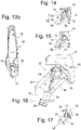
Fig. 13a die Armlehne gemäß Ansichtspfeil F2 inFig. 12 , wobei der Fahrzeugsitz der Übersichtlichkeit halber nicht dargestellt ist, -
Fig. 13b eine perspektivische Ansicht der Armlehne gemäßFig. 13a , -
Fig. 14 eine Ansicht gemäß Ansichtspfeil E2 inFig. 13a , -
Fig. 15 eine Schnittansicht gemäß Schnittlinie A2-A2 inFig. 13a -
Fig. 16 eine Schnittansicht gemäß Schnittlinie B2-B2 inFig. 13a , -
Fig. 17 eine Schnittansicht gemäß Schnittlinie C2 - C2 inFig. 13a , -
Fig. 18a eine Schnittansicht gemäß Schnittlinie D2 - D2 inFig. 14 , -
Fig. 18b eine vergrößerte Ansicht gemäß Ausschnitt H2 inFig. 18a , -
Fig. 19 eine Seitenansicht des Fahrzeugsitzes gemäßFig. 11 , wobei sich die Armauflage in der dritten Position der Lateralmechanik und in einer sekundären Position der Schwenkmechanik befindet, die zwischen der primären Position und der tertiären Position angeordnet ist, -
Fig. 20 eine Draufsicht gemäß Ansichtspfeil G3 inFig. 19 -
Fig. 21a eine Ansicht gemäß Ansichtspfeil F3Fig. 20 , wobei die Armlehne ohne die übrigen Bestandteile des Fahrzeugsitzes dargestellt ist, -
Fig. 21b eine perspektivische Ansicht der Armlehne gemäßFig. 21a , -
Fig. 22 eine Ansicht gemäß Ansichtspfeil E3 inFig. 21 , -
Fig. 23 eine Schnittansicht gemäß Schnittlinie A3 - A3 inFig. 21a -
Fig. 24 eine Schnittansicht gemäß Schnittlinie B3 - B3inFig. 21a , -
Fig. 25 eine Schnittansicht gemäß Schnittlinie C3 - C3 inFig. 21a , -
Fig. 26a eine Schnittansicht gemäß Schnittlinie D3 - D3 inFig. 22 , -
Fig. 26b ein Ausschnitt gemäß Ausschnittlinie H3 inFig. 26a , -
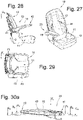
Fig. 27 eine perspektivische Darstellung des Fahrzeugsitzes, wobei sich die Armauflage in einer Gebrauchsposition befindet, -
Fig. 28 eine Seitenansicht des Fahrzeugsitzes, wobei sich die Armauflage in der distalen Position der Lateralmechanik und in der zweiten Position der Schwenkmechanik befindet, -
Fig. 29 eine Draufsicht gemäß Ansichtspfeil G4 inFig. 28 , -
Fig. 30a eine Seitenansicht der Armlehne gemäß Ansichtspfeil F4 inFig. 29 , wobei der Fahrzeugsitz der Übersichtlichkeit halber nicht dargestellt ist, -
Fig. 30b eine perspektivische Ansicht der Armauflage gemäßFig. 30a , -
Fig. 31 eine Ansicht gemäß Ansichtspfeil E4 inFig. 30a , -
Fig. 32 eine Schnittansicht gemäß Schnittlinie A4 - A4 inFig. 30a -
Fig. 33 eine Schnittansicht gemäß Schnittlinie B4 - B4 inFig. 30a , -
Fig. 34 eine Schnittansicht gemäß Schnittlinie C4 - C4 inFig. 30a , -
Fig. 35 eine Schnittansicht gemäß Schnittlinie D4 - D4 inFig. 31 , -
Fig. 36 eine vergrößerte Ansicht gemäß Ausschnittlinie H4 inFig. 35 . - Ein Fahrzeugsitz insgesamt ist in den Fig. mit dem Bezugszeichen 10 bezeichnet.
- Der Fahrzeugsitz 10 umfasst gemäß
Fig. 1 einen Sitzbereich 11 mit einer Sitzfläche 12 sowie eine Rückenlehne 13 mit einer Anlagefläche 14. Die Anlagefläche 14 weist in Richtung x1, parallel zu einer Sagittalebene eines Sitzinsassen. Die Richtung x2 ist der Richtung x1 entgegen gerichtet. - Der Fahrzeugsitz 10 weist eine Armlehne 20 auf, die entsprechend den Merkmalen der Erfindung ausgebildet ist. Die Armlehne 20 umfasst eine Armauflage 15, welche einen befestigungsnahen Endbereich 41 und einen freien Endbereich 42 sowie eine Armauflagefläche 43 umfasst. Mit einer Lateralmechanik 27 ist die Armauflage 15 in die Richtungen y1 und y2 zwischen einer in den
Fig. 1 bis 4 dargestellten proximalen ersten Position sowie einer in denFig. 19 bis 36 dargestellten distalen dritten Position bewegbar. - Die Lateralbewegung der Armauflage 15 erfolgt über eine in den
Fig. 11 bis 18b dargestellte zweite Position, in welcher sich die Lateralmechanik 27 in einer Zwischenposition zwischen der ersten Position und der zweiten Position befindet. In der ersten Position ist die Armauflage 15 bezüglich der Richtungen y1 und y2 relativ zu der Rückenlehne 13 proximal, d.h. nahe an der Rückenlehne 13, angeordnet und in der dritten Position ist die Armauflage 15 relativ zu der Rückenlehne 13 distal, d.h. in Richtung y2 von der Rückenlehne 13 entfernt, angeordnet. - Die Armauflage 15 ist z.B. mit einer Schwenkmechanik 28 in die Drehrichtungen u1 und u2 zwischen einer primären Position (siehe
Fig. 1 bis 18b ), und einer tertiären Position um eine Schwenkachse a schwenkbar, die in denFig. 27 bis 36 gezeigt ist. Eine Zwischenposition zwischen der primären Position und der tertiären Position ist als sekundäre Position bezeichnet und in denFig. 19 bis 26b dargestellt. - Die Armauflage 15 kann in umgekehrte Richtung u2 zwischen der tertiären und der primären Position der Schwenkmechanik 28 nach oben geschwenkt und aus der dritten Position in die erste Position der Lateralmechanik 27 bewegt werden.
- In den
Fig. 1 und 3 ist erkennbar, dass sich die Armauflage 15 in der ersten Position teilweise in x-Richtung hinter einer Insassen-Anlagefläche der Rückenlehne 13 befindet, so dass ein Schwenken der Armauflage 15 in Richtung u1 gemäßFig. 2 nicht möglich wäre, weil sich die Rückenlehne 13 in der Bewegungsbahn der Armauflage 15 befände. In dieser Position ragt die Armauflage 15 z. B. seitlich, d.h. bezüglich der Richtung y2, nicht oder lediglich geringfügig über die sich in Richtung y1 und y2 erstreckenden Dimensionen des Sitzbereichs 11 sowie der Rückenlehne 13 hinaus. - In
Fig. 4a und4b ist die Armlehne 20 ohne die übrigen Bestandteile des Fahrzeugsitzes separat dargestellt. Für die Lateralbewegung in die Richtungen y1 und y2 zwischen der ersten Position und der dritten Position der Armauflage 15 ist, wie oben beschrieben, die Lateralmechanik 27 vorgesehen, die nachfolgend näher erläutert wird. Ein erstes Teil 16 weist Befestigungsmittel 17 in Form eines Flansches auf (siehe die 5 bis 9a), mit welchem es fest an der Struktur der Rückenlehne 13 befestigt ist. Ein zweites Teil 18 ist mit der Armauflage 15 verbunden. - Das erste Teil 16 und das zweite Teil 18 sind untereinander mit einer Gelenkverbindung 37 verbunden. Z.B. ist die Gelenkverbindung 37 als Koppelgetriebe, insbesondere, wie im vorliegenden Ausführungsbeispiel, als Viergelenk ausgebildet. Die Bewegung des zweiten Teils erfolgt z.B. einer horizontalen x-y-Ebene ohne wesentlichen vertikalen z-Anteil der Bewegung.
- Die Gelenkverbindung 37 umfasst bei diesem Ausführungsbeispiel einen Lenker 19 sowie einen Lenker 21. Jeder der Lenker 19 und 21 bildet ein Schwenkgelenk mit dem ersten Teil 16 sowie mit dem zweiten Teil 18. Das erste Teil 16, das zweite Teil 18 sowie die Lenker 19 und 21 bilden ein Viergelenk 23. Die Armauflage 15 ist daher mittels des Viergelenks 23 auf einer Koppelkurve zwischen der ersten Position und der dritten Position bewegbar. Die erste Position und die dritte Position der lateralen Bewegungsmechanik 27 sind in Form nicht dargestellter Anschläge festgelegt.
- Das zweite Teil 18 ist zudem Träger für einen Teil der Schwenkmechanik 28. Es bildet mit einer Schwenkstruktur 22, mit welcher die Armauflage 15 fest verbunden ist, ein Schwenkgelenk S. Mit dem Schwenkgelenk S ist die Armauflage 15 um die Schwenkachse a, die von der fest mit dem zweiten Teil 18 verbundenen physischen Achse 31 gebildet ist, zwischen der primären Position und der tertiären Position schwenkbar an dem zweiten Teil 18 gehalten. Die primäre Position und die tertiäre Position der Schwenkmechanik 28 sind mit nicht dargestellten Anschlägen definiert.
- Grundsätzlich könnte die Armauflage 15 manuell in definierte Positionen bewegt und dort verriegelt werden. D. h., Lateralbewegung sowie die Schwenkbewegung wären manuell durchführbar.
- Alternativ wäre es ebenfalls möglich, dass alle vorgenannten Bewegungen der Armauflage 15, d.h. die Bewegung zwischen der ersten und der dritten Position der Lateralmechanik 27 sowie die Bewegung zwischen der primären Position und der tertiären Position der Schwenkmechanik 28 vollständig von wenigstens einem Antrieb angetrieben erfolgten.
- Gemäß einer weiteren Alternative wäre es möglich, dass die Lateralbewegung und/oder die Schwenkbewegung in wenigstens einem Teilbereich der Bewegung angetrieben erfolgt.
- Im vorliegenden Ausführungsbeispiel verläuft die Bewegung der Armauflage 15 teilautomatisch. Die Bewegung zwischen der ersten Position und der dritten Position wird bezüglich beider Bewegungsrichtungen vollständig angetrieben. Dafür weist die Armlehne 10 eine Antriebsvorrichtung mit einem Motor sowie einem Lateralgetriebe 35 auf.
- Die Bewegung zwischen der primären Position und einer sekundären Position (siehe
Fig. 19 ) erfolgt etwa über einen Winkel von etwa 45° relativ zu der primären Position motorisch angetrieben. Dafür weist die Armlehne 10 ein Schwenkgetriebe 36 auf. Die Bewegung zwischen der sekundären und der tertiären Position erfolgt automatisch und wird von der potentiellen Energie der Armauflage 15 angetrieben. - Im vorliegenden Ausführungsbeispiel werden die Lateralmechanik sowie die Schwenkmechanik von nur einem Antrieb 26, z.B. einem Elektromotor angetrieben. Alternativ wäre es ebenfalls möglich, dass die Lateralmechanik von einem ersten Antrieb angetrieben wird und die Schwenkmechanik von einem zweiten Antrieb angetrieben wird.
- Das Lateralgetriebe 35 umfasst im vorliegenden Ausführungsbeispiel eine Spindel 24, die mit einer Spindelmutter 25 in Eingriff steht (siehe z.B.
Fig. 7 ) und schwenkbar mit dem ersten Teil verbunden ist. Die Spindelmutter 25 ist fest mit einem der Lenker 19 oder 21, hier mit dem Lenker 21, verbunden. Die Spindel 24 ist mittels eines Motors 26 um ihre Längsmittelachse b drehbar. Auf diese Weise kann mittels des Lateralgetriebes 35, im vorliegenden Fall der Spindel 24 und der Spindelmutter 25, die Armauflage 15 zwischen der ersten und der dritten Position der Lateralmechanik 27 verstellt werden. Bereits in der zweiten Position (sieheFig. 10 ), in welcher die Lenker 19 und 21 bzgl. der ersten Position etwa um 45° geschwenkt werden, ist die Armauflage soweit in Richtung y1 bewegt, dass sich die Rückenlehne 13 nicht in der Schwenkbahn zwischen der primären Position und der tertiären Position der Armauflage 15 befindet. - Das Schwenkgetriebe 36 für die Bewegung zwischen der primären und der sekundären Position umfasst im vorliegenden Ausführungsbeispiel eine erste Verzahnung 29, hier in Form eines ersten Zahnrades (siehe
Fig. 9a und 9b ), welches auf dem Lenker 21 angeordnet und unbewegbar fest mit dem Lenker 21 verbunden ist sowie eine zweite Verzahnung 32, hier in Form eines mit der Armauflage 15 drehverbundenen und relativ zu der Achse 31 in die Richtungen u1 und u2 drehbaren zweiten Zahnrades. Die Achse 31 ist fest an dem zweiten Teil 18 gehalten. Die erste Verzahnung 29 sowie die zweite Verzahnung 32 sind im vorliegenden Fall lediglich von Viertelkreisverzahnungen gebildet. Sie könnten alternativ aber auch anders ausgebildet sein, z.B. als Vollkreisverzahnungen. Das Schwenkgetriebe 36 und das Lateralgetriebe 35 bewegen sich gleichzeitig. - Im vorliegenden Ausführungsbeispiel wird das Schwenkgetriebe 36 von der Relativbewegung des Koppelgetriebes angetrieben, also von der Relativbewegung eines Teils der Lateralmechanik 27 relativ zu dem zweiten Zahnrad 32.
- Die Armlehne 10 weist eine Kupplungsvorrichtung 34 auf, die z.B. in den
Fig. 16 und24 dargestellt ist. Mittels der Kupplungsvorrichtung 34 kann die Armauflage 15 von der Antriebsmechanik entkoppelt werden, so dass sie manuell bewegbar ist. Die Kupplungsvorrichtung 34 umfasst im vorliegenden Ausführungsbeispiel eine mit der Armauflage 15 verbundene erste Kupplungsstruktur 38 sowie eine fest mit dem zweiten Zahnrad verbundene zweite Kupplungsstruktur 39. Die erste Kupplungsstruktur 38 kann in Abhängigkeit von der relativen Drehposition zu der zweiten Kupplungsstruktur 39 lösbar in Eingriff mit der zweiten Kupplungsstruktur 39 bewegt werden. - Die Kupplungsstrukturen 38 und 39 bilden Steuerstrukturen, d. h. die Kupplung umfasst einen Freilaufbereich, in welchem die Kupplungsstrukturen 38 und 39 nicht in Eingriff sind sowie einen Eingriffsbereich, in welchem sich die Kupplungsstrukturen 38 und 39 in Eingriff befinden. Mit anderen Worten, in bestimmten Relativpositionen der ersten Verzahnung zu der zweiten Verzahnung 32 bewegen sich die Kupplungsstrukturen 38 und 39 in Eingriff. Eine Übertragung der Bewegung der zweiten Verzahnung findet statt, wenn die Kupplungsstrukturen 38 und 39 in einer Eingriffsposition in Eingriff stehen. In einer Löseposition sind die Kupplungsstrukturen 38 und 39 außer Eingriff und es findet keine Übertragung statt.
- Im vorliegenden Ausführungsbeispiel stehen die Kupplungsstrukturen 38 und 39 in Eingriff, wenn sich die Lateralmechanik 27 aus der ersten Position in die zweite Position bewegt hat. Zwischen der ersten Position und der zweiten Position der Lateralmechanik 27 befinden sich die Kupplungsstrukturen 38 und 39 in der Löseposition.
- Ferner weist die Armlehne 10 eine Steuervorrichtung 30 auf, die mit einer nicht dargestellten Sensorvorrichtung 40 zusammenwirkt. Diese weist nicht dargestellte Positionssensoren auf. Die Steuervorrichtung 30 steuert den Motor 26. Die Sensoren der Sensorvorrichtung 40 erkennen, ob sich die Lateralmechanik in der ersten oder der dritten Position befindet und ob die Schwenkmechanik 28 in der primären Position oder der tertiären Position steht oder ob sie aus der tertiären Position in die sekundäre Position bewegt wurde und die sekundäre Position erreicht hat.
- Nachfolgend wird der gesamte Bewegungsablauf der Armauflage 15 noch einmal vollständig erläutert.
- Z.B. nach Betätigung eines nicht dargestellten Schalters von einem Sitzinsassen erhält die Steuervorrichtung 30 das Signal, dass die Armauflage 15 aus der Nichtgebrauchsposition in eine Gebrauchsposition überführt werden soll. Die Armauflage 15 ist gemäß der
Fig. 1 bis 9b in der Nichtgebrauchsposition gezeigt. Von der Steuervorrichtung wird dann der Antrieb 26 aktiviert. Dieser bewegt die Spindelmutter 25 des Lateralgetriebes 35, so dass die Lateralmechanik 27 in eine erste Bewegungsrichtung der Koppelkurve bewegt wird. Aufgrund der Bewegung der Lateralmechanik wird auch das Schwenkgetriebe 36 angetrieben, so dass auch die Verzahnungen 38 und 39 aufeinander abwälzen. Die Veränderungen der Relativpositionen des Vielgelenkes relativ zu der zweiten Verzahnung 32 werden als Antrieb genutzt, um die Armauflage 15 zu schwenken. - Zu Beginn der Bewegung befinden sich der Lateralantrieb in der Position gemäß
Fig. 7 und der Schwenkantrieb 36 in der Position gemäßFig. 9b . - Aufgrund des Freilaufbereiches der Kupplungsvorrichtung 34 wälzt das Schwenkgetriebe 36 über einen bestimmten Bereich aufeinander ab, ohne dass die Armauflage 15 sich aus der primären Position (vgl. die
Fig. 1 und10 - 18b ) bewegt. Wenn der Freilaufbereich überwunden ist und sich die Kupplungsstrukturen 38 und 39 in der Eingriffsposition befinden, was in der zweiten Position der Lateralmechanik 27 der Fall ist (siehe dieFig. 10 bis 18b ), treibt das Schwenkgetriebe 36 bei der weiteren Bewegung die Armauflage 15 in Richtung u1 an. In der Eingriffsposition weisen die Verzahnungen 38 und 39 die Position gemäßFig. 18b auf. - Wenn die Armauflage 15 aus der primären Position einen bestimmten Schwenkwinkel in Richtung u1 zurückgelegt hat, belastet die Gewichtskraft die Armauflage 15 in Richtung u1. Die Kupplungsvorrichtung 34 lässt die Bewegung in Richtung u1 zu. Mittels eines Rotationsdämpfers wird verhindert, dass sich die Armauflage 15 unter Belastung durch die Gewichtskraft ungebremst in Richtung u1 in die tertiäre Position gemäß
Fig. 27 bis 36 bewegt. - Wenn die Lateralmechanik 27 die dritte Position erreicht hat, befindet sich das Lateralgetriebe 35 in der Position gemäß
Fig. 23 und das Schwenkgetriebe 36 in der Position gemäßFig. 26b , d.h. dass sich die Verzahnungen 29 und 32 an einem zweiten Endbereich befinden. Die Armauflage 15 ist gemäß derFig. 20 bis 26b in einer 45°-Position gezeigt, obwohl sie sich, wie oben erläutert, aufgrund der Freilaufbereiche der Kupplungsvorrichtung 34 unabhängig von dem Schwenkgetriebe 36 bewegen kann. Sobald über die Positionssensoren der Sensorvorrichtung 40 eine Rückmeldung gegeben wird, dass die dritte Position erreicht ist, gibt die Steuervorrichtung 30 ein Signal an die laterale Antriebsvorrichtung 27, den Antrieb 26 zu stoppen. - Die Aufwärtsbewegung findet in umgekehrte Richtung statt. Die Armauflage 15 wird aus der tertiären Position manuell in die sekundäre Position bewegt, während mittels der Kupplungsvorrichtung 34 die sekundäre Antriebsmechanik 36 weiterhin entkuppelt ist. Erreichen die Kupplungsstrukturen 38 und 39 die Eingriffsposition, wird die Kupplungsstruktur 39 mit der Kupplungsstruktur 38 - z.B. von einem nicht dargestellten Mitnahmestift - verrastet. Das Erreichen der sekundären Position der Armauflage 15 wird von der Sensorvorrichtung 40 an die Steuervorrichtung 30 übermittelt, woraufhin diese den Antrieb 26 zur Bewegung in umgekehrte Richtung veranlasst, derart, dass die Armauflage 15 in Richtung u2 schwenkt.
- Nach einem Schwenkradius von etwa 45° hat die Armauflage 15 wieder die primäre Position und die Lateralmechanik 27 hat die zweite Position erreicht. Die Verrastung der Kupplungsstrukturen 38 und 39 wird nun gelöst. Die Kupplungsvorrichtung 34 erlaubt eine zusätzliche Relativbewegung der Kupplungsstrukturen 38 und 39, ohne dass dabei die Armauflage 15 aus der primären Position bewegt wird. Die weitere Bewegung des Antriebs, d. h. des Motors 26, hat also keinen Einfluss auf die Schwenk-Position der Armauflage 15, weil diese sich danach wieder in dem Freilaufbereich befindet.
- Die Lateralmechanik 27 kann daher aus der zweiten in die erste Position bewegt werden. Sobald die erste Position erreicht wurde, wird der Antrieb von der Steuervorrichtung 30 angehalten.
Claims (14)
- Armlehne mit einer Armauflage (15) für einen Fahrzeugsitz (10), die mit einer Lateralmechanik (27) relativ zu einer Basis zwischen einer proximalen und einer distalen Position bewegbar ist und mit einer Schwenkmechanik (28) zwischen einer ersten Schwenkposition und einer zweiten Schwenkposition schwenkbar ist, wobei die Lateralmechanik (27) ein erstes Teil (16) der Basis und ein der Armauflage (15) zugeordnetes zweites Teil (18) umfasst, wobei das erste Teil (16) mit einer Gelenkverbindung (37) mit dem zweiten Teil (21) verbunden ist.
- Armlehne nach Anspruch 1, dadurch gekennzeichnet, dass die Gelenkverbindung (37) wenigstens ein Koppelgetriebe umfasst, welches insbesondere als wenigstens ein Viergelenk ausgebildet ist.
- Armlehne nach Anspruch 1, dadurch gekennzeichnet, dass die Relativbewegung eines der Lenker (21) des Koppelgetriebes relativ zu einem Element des Schwenkgetriebes, insbesondere des Viergelenks, zugleich Antrieb für das Schwenkgetriebe ist.
- Armlehne nach einem der vorangehenden Ansprüche, dadurch gekennzeichnet, dass die Schwenkmechanik (28) ein dem zweiten Teil zugeordnetes erstes Schwenkelement (18) sowie ein armauflagefestes zweites Schwenkelement umfasst, wobei das erste Schwenkelement und das zweite Schwenkelement miteinander ein Schwenkgelenk (S) bilden.
- Armlehne nach einem der vorangehenden Ansprüche, dadurch gekennzeichnet, dass die Lateralmechanik (27) mit einem Lateralgetriebe (35) antreibbar ist, wobei das Lateralgetriebe (35) ein erstes Antriebsteil aufweist, welches dem ersten Teil (16) zugeordnet ist und ein mit dem ersten Antriebsteil in Eingriff stehendes zweites Antriebsteil aufweist, welches dem zweiten Teil (18) zugeordnet ist.
- Armlehne nach einem der vorangehenden Ansprüche, dadurch gekennzeichnet, dass die dass die Schwenkmechanik (28) mit einem Schwenkgetriebe (36) antreibbar ist, wobei das Schwenkgetriebe (35) ein erstes Antriebsteil aufweist, welches dem zweiten Teil (18) zugeordnet ist und ein mit dem ersten Antriebsteil in Eingriff stehendes zweites Antriebsteil aufweist, welches der Armauflage (15) zugeordnet ist.
- Armlehne nach einem der vorangehenden Ansprüche, dadurch gekennzeichnet, dass eine Antriebsvorrichtung vorgesehen ist, welche das Lateralgetriebe (35) und / oder das Schwenkgetriebe (36) sowie wenigstens einen Motor und / oder einen Energiespeicher umfasst.
- Armlehne nach einem der vorangehenden Ansprüche, dadurch gekennzeichnet, dass wenigstens ein Antrieb von Lateralgetriebe (35) und Schwenkgetriebe (36) eine Spindel (24) umfasst, die mit einer Spindelmutter (25) in Eingriff steht, wobei die Spindel (24) oder die Spindelmutter (25) antreibbar ist.
- Armlehne nach einem der vorangehenden Ansprüche, dadurch gekennzeichnet, dass wenigstens ein Antrieb von Lateralgetriebe (35) und Schwenkgetriebe (36) ein erstes Zahnrad (29) sowie ein zweites Zahnrad (32) aufweist, wobei die Zahnräder (29, 32) in Eingriff stehen.
- Armlehne nach einem der vorangehenden Ansprüche, dadurch gekennzeichnet, dass mittels wenigstens einer Kupplungsvorrichtung (34) mit einer der Basis zugeordneten ersten Kupplungsstruktur (38) und einer der Armauflage (15) zugeordneten zweiten Kupplungsstruktur (39) das Lateralgetriebe (35) und / oder das Schwenkgetriebe (36) mit der Armauflage (15) lösbar kuppelbar ist.
- Armlehne nach einem der vorangehenden Ansprüche, dadurch gekennzeichnet, dass die Kupplungsvorrichtung (34) die erste Kupplungsstruktur (38) mit einem ersten Antriebsteil und die zweite Kupplungsstruktur (39) mit einem zweiten Antriebsteil des Lateralgetriebes und / oder des Schwenkgetriebes verbunden ist.
- Armlehne nach einem der vorangehenden Ansprüche, dadurch gekennzeichnet, dass eine Steuervorrichtung (30) vorgesehen ist, welche das Lateralgetriebe (35) und das Schwenkgetriebe (36) steuert.
- Armlehne nach Anspruch 12, dadurch gekennzeichnet, dass eine Sensorvorrichtung (40) vorgesehen ist, welche Positionssensoren umfasst, mit welchen die Position der Armauflage (15) ermittelbar ist und mit welcher die ermittelten Daten an die Steuervorrichtung (30) übertragbar sind.
- Armlehne nach Anspruch 12, dadurch gekennzeichnet, dass Armlehne nach Anspruch 12, dadurch gekennzeichnet, dass eine Arretiervorrichtung vorgesehen ist, mittels welcher die Lateralmechanik (27) und / oder die Schwenkmechanik (28) in wenigstens einer Position verriegelbar ist.
Applications Claiming Priority (1)
| Application Number | Priority Date | Filing Date | Title |
|---|---|---|---|
| DE102021112868.4A DE102021112868A1 (de) | 2021-05-18 | 2021-05-18 | Armlehne |
Publications (2)
| Publication Number | Publication Date |
|---|---|
| EP4091875A1 true EP4091875A1 (de) | 2022-11-23 |
| EP4091875B1 EP4091875B1 (de) | 2025-04-02 |
Family
ID=81653463
Family Applications (1)
| Application Number | Title | Priority Date | Filing Date |
|---|---|---|---|
| EP22173312.4A Active EP4091875B1 (de) | 2021-05-18 | 2022-05-13 | Armlehne |
Country Status (3)
| Country | Link |
|---|---|
| US (1) | US11827131B2 (de) |
| EP (1) | EP4091875B1 (de) |
| DE (1) | DE102021112868A1 (de) |
Families Citing this family (2)
| Publication number | Priority date | Publication date | Assignee | Title |
|---|---|---|---|---|
| KR20250089663A (ko) * | 2023-12-12 | 2025-06-19 | 현대자동차주식회사 | 회전 메커니즘 및 이를 포함하는 시트 |
| DE102024136303A1 (de) | 2024-08-30 | 2026-03-05 | Grammer Aktiengesellschaft | Armlehne für einen Fahrzeugsitz |
Citations (2)
| Publication number | Priority date | Publication date | Assignee | Title |
|---|---|---|---|---|
| US7469964B2 (en) * | 2005-09-07 | 2008-12-30 | Recaro Aircraft Seating Gmbh & Co. Kg | Seating system for passenger service vehicles, for aircraft in particular |
| DE102019000119A1 (de) | 2019-01-11 | 2020-07-16 | Grammer Ag | Armlehne |
Family Cites Families (6)
| Publication number | Priority date | Publication date | Assignee | Title |
|---|---|---|---|---|
| SE527730C2 (sv) * | 2004-10-07 | 2006-05-23 | Volvo Constr Equip Holding Se | Fällbart armstöd för ett fordonssäte |
| FR2885329A1 (fr) | 2005-05-04 | 2006-11-10 | Peugeot Citroen Automobiles Sa | Accoudoir a double articulation pour siege de vehicule automobile |
| DE102010013041A1 (de) * | 2010-03-26 | 2011-09-29 | Bomag Gmbh | Bedienarbeitsplatz einer Baumaschine |
| CN109070779B (zh) * | 2016-04-29 | 2021-11-05 | 恺博座椅机械部件有限公司 | 用于车辆座椅的扶手和车辆座椅 |
| US10723249B2 (en) | 2018-06-20 | 2020-07-28 | Ford Global Technologies, Llc | Adjustable armrest assembly |
| DE102018008817B3 (de) | 2018-11-09 | 2019-10-31 | Grammer Ag | Armlehne |
-
2021
- 2021-05-18 DE DE102021112868.4A patent/DE102021112868A1/de active Pending
-
2022
- 2022-05-12 US US17/743,068 patent/US11827131B2/en active Active
- 2022-05-13 EP EP22173312.4A patent/EP4091875B1/de active Active
Patent Citations (2)
| Publication number | Priority date | Publication date | Assignee | Title |
|---|---|---|---|---|
| US7469964B2 (en) * | 2005-09-07 | 2008-12-30 | Recaro Aircraft Seating Gmbh & Co. Kg | Seating system for passenger service vehicles, for aircraft in particular |
| DE102019000119A1 (de) | 2019-01-11 | 2020-07-16 | Grammer Ag | Armlehne |
Also Published As
| Publication number | Publication date |
|---|---|
| US20220371495A1 (en) | 2022-11-24 |
| EP4091875B1 (de) | 2025-04-02 |
| US11827131B2 (en) | 2023-11-28 |
| DE102021112868A1 (de) | 2022-11-24 |
Similar Documents
| Publication | Publication Date | Title |
|---|---|---|
| DE60035085T2 (de) | Teleskopische welle für kraftfahrzeuglenksäulen mit einem gleitsteuersystem | |
| DE102009006387B4 (de) | Vorrichtung zur elektrischen Einstellung eines Fahrzeugsitzes | |
| DE3525374A1 (de) | Hoeheneinstelleinrichtung fuer einen fahrzeugsitz | |
| EP1002693A2 (de) | Motorischer Kopfstützen-Verstellantrieb für Fahrzeugsitze | |
| DE102015201232A1 (de) | Fahrzeugsitz | |
| EP3996553B1 (de) | Klappsitz für ein schienenfahrzeug | |
| DE3230256A1 (de) | Lenksystem fuer ein fahrzeug | |
| DE3013774A1 (de) | Betaetigungsanordnung fuer fluegelklappen | |
| DE3345985A1 (de) | Flugzeugfahrwerk | |
| DE19935161C2 (de) | Gelenk, insbesondere für einen Kraftfahrzeugsitz | |
| EP4091875B1 (de) | Armlehne | |
| DE3406359A1 (de) | Frontfahrwerk fuer luftfahrzeug | |
| DE102006039270A1 (de) | Einstellbare Pedalanordnung | |
| EP1272909B1 (de) | Verstellbare pedalwerke | |
| DE102018109611B4 (de) | Kopfstütze | |
| DE102009027464A1 (de) | Sitzgestell eines Kraftfahrzeugsitzes | |
| DE4302329B4 (de) | Höhenverstelleinrichtung für Sitze, insbesondere Kraftfahrzeugsitze | |
| DE1238788B (de) | Progressive Lenkung fuer Kraftfahrzeuge | |
| EP0755824A1 (de) | Fahrzeugsitz | |
| DE102021134098B4 (de) | Ausstattungsteil für ein Fahrzeug | |
| WO2002047976A2 (de) | Aerodynamischer flügel mit zumindest bereichsweise variabler wölbung sowie struktur-gelenke | |
| DE102020134716B4 (de) | Verlagerbares Bauteil eines Kraftfahrzeuges | |
| DE102019131595B4 (de) | Fahrzeugsitz | |
| DE3346608C2 (de) | ||
| DE102018002479B4 (de) | Verstellvorrichtung für einen Fahrzeugsitz, Fahrzeugsitzanordnung und Fahrzeug |
Legal Events
| Date | Code | Title | Description |
|---|---|---|---|
| PUAI | Public reference made under article 153(3) epc to a published international application that has entered the european phase |
Free format text: ORIGINAL CODE: 0009012 |
|
| STAA | Information on the status of an ep patent application or granted ep patent |
Free format text: STATUS: THE APPLICATION HAS BEEN PUBLISHED |
|
| AK | Designated contracting states |
Kind code of ref document: A1 Designated state(s): AL AT BE BG CH CY CZ DE DK EE ES FI FR GB GR HR HU IE IS IT LI LT LU LV MC MK MT NL NO PL PT RO RS SE SI SK SM TR |
|
| STAA | Information on the status of an ep patent application or granted ep patent |
Free format text: STATUS: REQUEST FOR EXAMINATION WAS MADE |
|
| 17P | Request for examination filed |
Effective date: 20230523 |
|
| RBV | Designated contracting states (corrected) |
Designated state(s): AL AT BE BG CH CY CZ DE DK EE ES FI FR GB GR HR HU IE IS IT LI LT LU LV MC MK MT NL NO PL PT RO RS SE SI SK SM TR |
|
| RIC1 | Information provided on ipc code assigned before grant |
Ipc: B60N 2/75 20180101AFI20240923BHEP |
|
| GRAP | Despatch of communication of intention to grant a patent |
Free format text: ORIGINAL CODE: EPIDOSNIGR1 |
|
| STAA | Information on the status of an ep patent application or granted ep patent |
Free format text: STATUS: GRANT OF PATENT IS INTENDED |
|
| INTG | Intention to grant announced |
Effective date: 20241118 |
|
| GRAS | Grant fee paid |
Free format text: ORIGINAL CODE: EPIDOSNIGR3 |
|
| P01 | Opt-out of the competence of the unified patent court (upc) registered |
Free format text: CASE NUMBER: APP_3520/2025 Effective date: 20250122 |
|
| GRAA | (expected) grant |
Free format text: ORIGINAL CODE: 0009210 |
|
| STAA | Information on the status of an ep patent application or granted ep patent |
Free format text: STATUS: THE PATENT HAS BEEN GRANTED |
|
| AK | Designated contracting states |
Kind code of ref document: B1 Designated state(s): AL AT BE BG CH CY CZ DE DK EE ES FI FR GB GR HR HU IE IS IT LI LT LU LV MC MK MT NL NO PL PT RO RS SE SI SK SM TR |
|
| REG | Reference to a national code |
Ref country code: GB Ref legal event code: FG4D Free format text: NOT ENGLISH |
|
| REG | Reference to a national code |
Ref country code: CH Ref legal event code: EP |
|
| REG | Reference to a national code |
Ref country code: IE Ref legal event code: FG4D Free format text: LANGUAGE OF EP DOCUMENT: GERMAN |
|
| REG | Reference to a national code |
Ref country code: DE Ref legal event code: R096 Ref document number: 502022003387 Country of ref document: DE |
|
| PGFP | Annual fee paid to national office [announced via postgrant information from national office to epo] |
Ref country code: DE Payment date: 20250528 Year of fee payment: 4 |
|
| PGFP | Annual fee paid to national office [announced via postgrant information from national office to epo] |
Ref country code: FR Payment date: 20250528 Year of fee payment: 4 |
|
| PGFP | Annual fee paid to national office [announced via postgrant information from national office to epo] |
Ref country code: AT Payment date: 20250721 Year of fee payment: 4 |
|
| REG | Reference to a national code |
Ref country code: NL Ref legal event code: MP Effective date: 20250402 |
|
| PG25 | Lapsed in a contracting state [announced via postgrant information from national office to epo] |
Ref country code: NL Free format text: LAPSE BECAUSE OF FAILURE TO SUBMIT A TRANSLATION OF THE DESCRIPTION OR TO PAY THE FEE WITHIN THE PRESCRIBED TIME-LIMIT Effective date: 20250402 |
|
| PG25 | Lapsed in a contracting state [announced via postgrant information from national office to epo] |
Ref country code: ES Free format text: LAPSE BECAUSE OF FAILURE TO SUBMIT A TRANSLATION OF THE DESCRIPTION OR TO PAY THE FEE WITHIN THE PRESCRIBED TIME-LIMIT Effective date: 20250402 Ref country code: PT Free format text: LAPSE BECAUSE OF FAILURE TO SUBMIT A TRANSLATION OF THE DESCRIPTION OR TO PAY THE FEE WITHIN THE PRESCRIBED TIME-LIMIT Effective date: 20250804 Ref country code: FI Free format text: LAPSE BECAUSE OF FAILURE TO SUBMIT A TRANSLATION OF THE DESCRIPTION OR TO PAY THE FEE WITHIN THE PRESCRIBED TIME-LIMIT Effective date: 20250402 |
|
| REG | Reference to a national code |
Ref country code: LT Ref legal event code: MG9D |
|
| PG25 | Lapsed in a contracting state [announced via postgrant information from national office to epo] |
Ref country code: NO Free format text: LAPSE BECAUSE OF FAILURE TO SUBMIT A TRANSLATION OF THE DESCRIPTION OR TO PAY THE FEE WITHIN THE PRESCRIBED TIME-LIMIT Effective date: 20250702 Ref country code: GR Free format text: LAPSE BECAUSE OF FAILURE TO SUBMIT A TRANSLATION OF THE DESCRIPTION OR TO PAY THE FEE WITHIN THE PRESCRIBED TIME-LIMIT Effective date: 20250703 |
|
| PG25 | Lapsed in a contracting state [announced via postgrant information from national office to epo] |
Ref country code: PL Free format text: LAPSE BECAUSE OF FAILURE TO SUBMIT A TRANSLATION OF THE DESCRIPTION OR TO PAY THE FEE WITHIN THE PRESCRIBED TIME-LIMIT Effective date: 20250402 |
|
| PG25 | Lapsed in a contracting state [announced via postgrant information from national office to epo] |
Ref country code: BG Free format text: LAPSE BECAUSE OF FAILURE TO SUBMIT A TRANSLATION OF THE DESCRIPTION OR TO PAY THE FEE WITHIN THE PRESCRIBED TIME-LIMIT Effective date: 20250402 |
|
| PG25 | Lapsed in a contracting state [announced via postgrant information from national office to epo] |
Ref country code: HR Free format text: LAPSE BECAUSE OF FAILURE TO SUBMIT A TRANSLATION OF THE DESCRIPTION OR TO PAY THE FEE WITHIN THE PRESCRIBED TIME-LIMIT Effective date: 20250402 |
|
| PG25 | Lapsed in a contracting state [announced via postgrant information from national office to epo] |
Ref country code: RS Free format text: LAPSE BECAUSE OF FAILURE TO SUBMIT A TRANSLATION OF THE DESCRIPTION OR TO PAY THE FEE WITHIN THE PRESCRIBED TIME-LIMIT Effective date: 20250702 |
|
| PG25 | Lapsed in a contracting state [announced via postgrant information from national office to epo] |
Ref country code: IS Free format text: LAPSE BECAUSE OF FAILURE TO SUBMIT A TRANSLATION OF THE DESCRIPTION OR TO PAY THE FEE WITHIN THE PRESCRIBED TIME-LIMIT Effective date: 20250802 |
|
| PG25 | Lapsed in a contracting state [announced via postgrant information from national office to epo] |
Ref country code: LV Free format text: LAPSE BECAUSE OF FAILURE TO SUBMIT A TRANSLATION OF THE DESCRIPTION OR TO PAY THE FEE WITHIN THE PRESCRIBED TIME-LIMIT Effective date: 20250402 |
|
| REG | Reference to a national code |
Ref country code: CH Ref legal event code: H13 Free format text: ST27 STATUS EVENT CODE: U-0-0-H10-H13 (AS PROVIDED BY THE NATIONAL OFFICE) Effective date: 20251223 |
|
| REG | Reference to a national code |
Ref country code: DE Ref legal event code: R097 Ref document number: 502022003387 Country of ref document: DE |
|
| PG25 | Lapsed in a contracting state [announced via postgrant information from national office to epo] |
Ref country code: SM Free format text: LAPSE BECAUSE OF FAILURE TO SUBMIT A TRANSLATION OF THE DESCRIPTION OR TO PAY THE FEE WITHIN THE PRESCRIBED TIME-LIMIT Effective date: 20250402 Ref country code: DK Free format text: LAPSE BECAUSE OF FAILURE TO SUBMIT A TRANSLATION OF THE DESCRIPTION OR TO PAY THE FEE WITHIN THE PRESCRIBED TIME-LIMIT Effective date: 20250402 |
|
| PG25 | Lapsed in a contracting state [announced via postgrant information from national office to epo] |
Ref country code: LU Free format text: LAPSE BECAUSE OF NON-PAYMENT OF DUE FEES Effective date: 20250513 |
|
| PG25 | Lapsed in a contracting state [announced via postgrant information from national office to epo] |
Ref country code: CH Free format text: LAPSE BECAUSE OF NON-PAYMENT OF DUE FEES Effective date: 20250531 |
|
| PG25 | Lapsed in a contracting state [announced via postgrant information from national office to epo] |
Ref country code: CZ Free format text: LAPSE BECAUSE OF FAILURE TO SUBMIT A TRANSLATION OF THE DESCRIPTION OR TO PAY THE FEE WITHIN THE PRESCRIBED TIME-LIMIT Effective date: 20250402 |
|
| PG25 | Lapsed in a contracting state [announced via postgrant information from national office to epo] |
Ref country code: EE Free format text: LAPSE BECAUSE OF FAILURE TO SUBMIT A TRANSLATION OF THE DESCRIPTION OR TO PAY THE FEE WITHIN THE PRESCRIBED TIME-LIMIT Effective date: 20250402 |
|
| PG25 | Lapsed in a contracting state [announced via postgrant information from national office to epo] |
Ref country code: SK Free format text: LAPSE BECAUSE OF FAILURE TO SUBMIT A TRANSLATION OF THE DESCRIPTION OR TO PAY THE FEE WITHIN THE PRESCRIBED TIME-LIMIT Effective date: 20250402 |
|
| PG25 | Lapsed in a contracting state [announced via postgrant information from national office to epo] |
Ref country code: IT Free format text: LAPSE BECAUSE OF FAILURE TO SUBMIT A TRANSLATION OF THE DESCRIPTION OR TO PAY THE FEE WITHIN THE PRESCRIBED TIME-LIMIT Effective date: 20250402 |
|
| REG | Reference to a national code |
Ref country code: BE Ref legal event code: MM Effective date: 20250531 |
|
| PG25 | Lapsed in a contracting state [announced via postgrant information from national office to epo] |
Ref country code: MC Free format text: LAPSE BECAUSE OF FAILURE TO SUBMIT A TRANSLATION OF THE DESCRIPTION OR TO PAY THE FEE WITHIN THE PRESCRIBED TIME-LIMIT Effective date: 20250402 |
|
| PLBE | No opposition filed within time limit |
Free format text: ORIGINAL CODE: 0009261 |
|
| STAA | Information on the status of an ep patent application or granted ep patent |
Free format text: STATUS: NO OPPOSITION FILED WITHIN TIME LIMIT |
|
| PG25 | Lapsed in a contracting state [announced via postgrant information from national office to epo] |
Ref country code: RO Free format text: LAPSE BECAUSE OF FAILURE TO SUBMIT A TRANSLATION OF THE DESCRIPTION OR TO PAY THE FEE WITHIN THE PRESCRIBED TIME-LIMIT Effective date: 20250402 |
|
| REG | Reference to a national code |
Ref country code: CH Ref legal event code: L10 Free format text: ST27 STATUS EVENT CODE: U-0-0-L10-L00 (AS PROVIDED BY THE NATIONAL OFFICE) Effective date: 20260211 |
|
| 26N | No opposition filed |
Effective date: 20260105 |
|
| PG25 | Lapsed in a contracting state [announced via postgrant information from national office to epo] |
Ref country code: IE Free format text: LAPSE BECAUSE OF NON-PAYMENT OF DUE FEES Effective date: 20250513 |
|
| PG25 | Lapsed in a contracting state [announced via postgrant information from national office to epo] |
Ref country code: BE Free format text: LAPSE BECAUSE OF NON-PAYMENT OF DUE FEES Effective date: 20250531 |