EP4091581B1 - Armature à commissures souples - Google Patents
Armature à commissures souples Download PDFInfo
- Publication number
- EP4091581B1 EP4091581B1 EP22183861.8A EP22183861A EP4091581B1 EP 4091581 B1 EP4091581 B1 EP 4091581B1 EP 22183861 A EP22183861 A EP 22183861A EP 4091581 B1 EP4091581 B1 EP 4091581B1
- Authority
- EP
- European Patent Office
- Prior art keywords
- frame
- struts
- axial
- rows
- angled struts
- Prior art date
- Legal status (The legal status is an assumption and is not a legal conclusion. Google has not performed a legal analysis and makes no representation as to the accuracy of the status listed.)
- Active
Links
- 210000003709 heart valve Anatomy 0.000 claims description 25
- 239000000463 material Substances 0.000 claims description 19
- 229910045601 alloy Inorganic materials 0.000 claims description 11
- 239000000956 alloy Substances 0.000 claims description 11
- PXHVJJICTQNCMI-UHFFFAOYSA-N Nickel Chemical compound [Ni] PXHVJJICTQNCMI-UHFFFAOYSA-N 0.000 claims description 6
- 239000008280 blood Substances 0.000 claims description 4
- 210000004369 blood Anatomy 0.000 claims description 4
- 238000002788 crimping Methods 0.000 claims description 4
- 238000002513 implantation Methods 0.000 claims description 4
- 239000010935 stainless steel Substances 0.000 claims description 4
- 229910001220 stainless steel Inorganic materials 0.000 claims description 4
- 230000001351 cycling effect Effects 0.000 claims description 3
- 229910052759 nickel Inorganic materials 0.000 claims description 3
- WAIPAZQMEIHHTJ-UHFFFAOYSA-N [Cr].[Co] Chemical class [Cr].[Co] WAIPAZQMEIHHTJ-UHFFFAOYSA-N 0.000 claims description 2
- PRQRQKBNBXPISG-UHFFFAOYSA-N chromium cobalt molybdenum nickel Chemical compound [Cr].[Co].[Ni].[Mo] PRQRQKBNBXPISG-UHFFFAOYSA-N 0.000 claims description 2
- SZMZREIADCOWQA-UHFFFAOYSA-N chromium cobalt nickel Chemical compound [Cr].[Co].[Ni] SZMZREIADCOWQA-UHFFFAOYSA-N 0.000 claims description 2
- HLXZNVUGXRDIFK-UHFFFAOYSA-N nickel titanium Chemical compound [Ti].[Ti].[Ti].[Ti].[Ti].[Ti].[Ti].[Ti].[Ti].[Ti].[Ti].[Ni].[Ni].[Ni].[Ni].[Ni].[Ni].[Ni].[Ni].[Ni].[Ni].[Ni].[Ni].[Ni].[Ni] HLXZNVUGXRDIFK-UHFFFAOYSA-N 0.000 claims description 2
- 229910001000 nickel titanium Inorganic materials 0.000 claims description 2
- 229920000642 polymer Polymers 0.000 claims description 2
- 239000000602 vitallium Substances 0.000 claims description 2
- 238000009434 installation Methods 0.000 claims 1
- 238000000034 method Methods 0.000 description 14
- 229920000139 polyethylene terephthalate Polymers 0.000 description 6
- 239000005020 polyethylene terephthalate Substances 0.000 description 6
- 230000007246 mechanism Effects 0.000 description 5
- 210000001765 aortic valve Anatomy 0.000 description 4
- 230000000994 depressogenic effect Effects 0.000 description 3
- 210000000709 aorta Anatomy 0.000 description 2
- 210000004351 coronary vessel Anatomy 0.000 description 2
- 238000013016 damping Methods 0.000 description 2
- 230000006870 function Effects 0.000 description 2
- 238000003780 insertion Methods 0.000 description 2
- 230000037431 insertion Effects 0.000 description 2
- 229920002994 synthetic fiber Polymers 0.000 description 2
- 241000283690 Bos taurus Species 0.000 description 1
- VYZAMTAEIAYCRO-UHFFFAOYSA-N Chromium Chemical compound [Cr] VYZAMTAEIAYCRO-UHFFFAOYSA-N 0.000 description 1
- 229910000684 Cobalt-chrome Inorganic materials 0.000 description 1
- ZOKXTWBITQBERF-UHFFFAOYSA-N Molybdenum Chemical compound [Mo] ZOKXTWBITQBERF-UHFFFAOYSA-N 0.000 description 1
- 238000005452 bending Methods 0.000 description 1
- 230000000903 blocking effect Effects 0.000 description 1
- 230000000747 cardiac effect Effects 0.000 description 1
- 229910052804 chromium Inorganic materials 0.000 description 1
- 239000011651 chromium Substances 0.000 description 1
- 239000010941 cobalt Substances 0.000 description 1
- 229910017052 cobalt Inorganic materials 0.000 description 1
- GUTLYIVDDKVIGB-UHFFFAOYSA-N cobalt atom Chemical compound [Co] GUTLYIVDDKVIGB-UHFFFAOYSA-N 0.000 description 1
- 239000010952 cobalt-chrome Substances 0.000 description 1
- 238000005260 corrosion Methods 0.000 description 1
- 230000007797 corrosion Effects 0.000 description 1
- 125000004122 cyclic group Chemical group 0.000 description 1
- 230000000694 effects Effects 0.000 description 1
- 238000005516 engineering process Methods 0.000 description 1
- 239000004744 fabric Substances 0.000 description 1
- 210000001105 femoral artery Anatomy 0.000 description 1
- 210000005240 left ventricle Anatomy 0.000 description 1
- 210000004115 mitral valve Anatomy 0.000 description 1
- 229910052750 molybdenum Inorganic materials 0.000 description 1
- 239000011733 molybdenum Substances 0.000 description 1
- -1 polyethylene terephthalate Polymers 0.000 description 1
- 230000008569 process Effects 0.000 description 1
- 230000002685 pulmonary effect Effects 0.000 description 1
- 210000003102 pulmonary valve Anatomy 0.000 description 1
- 230000008707 rearrangement Effects 0.000 description 1
- 230000009467 reduction Effects 0.000 description 1
- 230000003014 reinforcing effect Effects 0.000 description 1
- 210000000591 tricuspid valve Anatomy 0.000 description 1
- 210000005166 vasculature Anatomy 0.000 description 1
- 210000003462 vein Anatomy 0.000 description 1
- 210000002073 venous valve Anatomy 0.000 description 1
Images


Classifications
-
- A—HUMAN NECESSITIES
- A61—MEDICAL OR VETERINARY SCIENCE; HYGIENE
- A61F—FILTERS IMPLANTABLE INTO BLOOD VESSELS; PROSTHESES; DEVICES PROVIDING PATENCY TO, OR PREVENTING COLLAPSING OF, TUBULAR STRUCTURES OF THE BODY, e.g. STENTS; ORTHOPAEDIC, NURSING OR CONTRACEPTIVE DEVICES; FOMENTATION; TREATMENT OR PROTECTION OF EYES OR EARS; BANDAGES, DRESSINGS OR ABSORBENT PADS; FIRST-AID KITS
- A61F2/00—Filters implantable into blood vessels; Prostheses, i.e. artificial substitutes or replacements for parts of the body; Appliances for connecting them with the body; Devices providing patency to, or preventing collapsing of, tubular structures of the body, e.g. stents
- A61F2/02—Prostheses implantable into the body
- A61F2/24—Heart valves ; Vascular valves, e.g. venous valves; Heart implants, e.g. passive devices for improving the function of the native valve or the heart muscle; Transmyocardial revascularisation [TMR] devices; Valves implantable in the body
- A61F2/2412—Heart valves ; Vascular valves, e.g. venous valves; Heart implants, e.g. passive devices for improving the function of the native valve or the heart muscle; Transmyocardial revascularisation [TMR] devices; Valves implantable in the body with soft flexible valve members, e.g. tissue valves shaped like natural valves
- A61F2/2418—Scaffolds therefor, e.g. support stents
Definitions
- This disclosure is in the field of prosthetic heart valves, stents for use with prosthetic heart valves.
- Existing frames for prosthetic heart valves typically comprise rows of angled struts and a plurality of axial frame members spaced apart around the circumference of the frame.
- the plurality of axial frame members may comprise a plurality of leaflet attachment members (for attaching to the commissures of the supported valvular structure) and a multitude of axially directed struts extending between the rows of angled struts.
- a frame usually has three or more axially directed struts for every leaflet attachment member, and generally has no more than two angled struts located in between adjacent struts or other axial frame members. Indeed, having a large number of axially directed struts is perceived to be necessary for preserving the structural stability of the stent and/or valve. Unfortunately, having a large number of axial struts can come at the expense of valve flexibility.
- WO 2013/155474 A1 discloses a frame for a prosthetic valve frame having a plurality of axial frame members comprises a plurality of axially extending leaflet attachment members and a plurality of axial struts in a 1:1 ratio.
- a prosthetic device for implantation at a cardiac valve annulus has an annular frame with an inflow end, an outflow end, and a plurality of axial frame members bridging two circumferentially extending rows of angled struts, wherein the plurality of axial frame members comprises a plurality of axially extending leaflet attachment members and a plurality of axial struts in a 1:1 ratio.
- the device comprises a leaflet structure positioned within the frame, the leaflet structure having a plurality of commissures that are secured to the frame at the leaflet attachment members.
- At least three angled struts separate adjacent axial frame members along each of the two rows of angled struts.
- exactly six angled struts separate adjacent leaflet attachment members along each of the two rows of angled struts, and exactly three angled struts separate adjacent axial frame members along each of the two rows of angled struts, such that each axial strut is positioned halfway between adjacent leaflet attachment members.
- each axial frame member extends between locations defined by the convergence of adjacent angled struts.
- the device further comprises an inner skirt secured to an interior portion of the annular frame, and an outer skirt secured to an exterior portion of the annular frame.
- the frame comprises exactly four rows of angled struts.
- the valve member comprises exactly three leaflets arranged in a tricuspid configuration, wherein the frame comprises exactly three axial struts and exactly three leaflet attachment members, and wherein the exactly three angled struts separate adjacent axial frame members along each of the two rows of angled struts.
- an annular frame for a prosthetic heart valve can comprise an inflow end, an outflow end, and a plurality of axial frame members spaced angularly around the circumference of the frame.
- the plurality of axial frame members can bridge two circumferentially extending rows of angled struts, wherein each of the two rows comprise at least three angled struts between adjacent axial frame members.
- each of the two rows comprises exactly three angled struts between adjacent axial frame members.
- the plurality of axial frame members comprises a plurality of axially extending leaflet attachment members, and each of the two rows comprises exactly six angled struts between adjacent leaflet attachment members.
- the plurality of axial frame members comprises a plurality of axially extending leaflet attachment members, wherein each of the two rows comprises four angled struts between adjacent axial frame members and eight angled struts between adjacent leaflet attachment members.
- the plurality of axial frame members comprises exactly three leaflet attachment members and exactly three axial struts.
- the leaflet attachment members extend between locations defined by the convergence of the upper ends of adjacent angled struts of each row of angled struts, and the axial struts extend between locations defined by the convergence of the lower ends of adjacent angled struts of each row of angled struts.
- the two rows of angled struts can comprise a first row and a second row, wherein the first row is closer to the outflow end than the second row.
- the leaflet attachment members extend from locations defined by the convergence of the upper ends of adjacent angled struts along the first row of angled struts to locations defined by the convergence of the lower ends of adjacent angled struts along the second row of angled struts, and the axial struts extend between locations defined by the convergence of the lower ends of adjacent angled struts along the first row of angled struts to locations defined by the convergence of upper ends of adjacent angled struts along the second row of angled struts.
- the leaflet attachment members extend from locations defined by the convergence of the upper ends of adjacent angled struts along the first row of angled struts to locations defined by the convergence of the upper ends of adjacent angled struts along the second row of angled struts, and the axial struts extend between locations defined by the convergence of the lower ends of adjacent angled struts along the first row of angled struts to locations defined by the convergence of lower ends of adjacent angled struts along the second row of angled struts.
- the frame comprises exactly four rows of angled struts.
- a prosthetic device for implantation at a cardiac valve annulus comprising an annular frame having an inflow end, an outflow end, at least four rows of circumferentially extending angled struts, and exactly six axial frame members bridging two rows of the four rows of circumferentially extending angled struts.
- the plurality of axial frame members can comprise exactly three axially extending leaflet attachment members and exactly three axial struts, wherein each of the two rows comprises exactly three angled struts between each adjacent pair of a leaflet attachment member and an axial strut, and exactly six angled struts between adjacent leaflet attachment members.
- the device can further comprise a tri-leaflet valve member positioned within the frame having commissures that are secured to the frame at the leaflet attachment members.
- prosthetic heart valves and stents for use with such valves that are capable of a high degree of flexibility.
- This flexibility can be useful for delivery to the valve annulus (such as for crimping/expanding a transcatheter heart valve (THV)) and/or for accommodating movement of the valve during cardiac cycling.
- strategically selected locations around the circumference of the frame are without axial struts, resulting in the improved flexibility.
- the flexibility of the commissures is enhanced as a result of an increase in the distance between each commissure and the nearest axial frame member (other than any support member located at the commissure such as a commissure support or window frame member).
- the frame can have one or more circumferentially extending rows of struts with three continuous angled struts between one or more pairs of axial supports. In some embodiments, these one or more rows of struts are located towards an outflow end of the frame. In some embodiments, the frame can have two rows of circumferentially extending struts (towards the outflow end of the valve) having three continuous angled struts between pairs of axial supports. In some embodiments, the frame has three continuous angled struts separating each commissure support (located at each commissure) from the nearest axial support. In another embodiment, there are four such angled struts separating each commissure support from the nearest axial strut.
- an "axial support” is a junction where at least three struts are connected, such as two angled struts connecting to a single axial strut or a junction of two angled struts and another axial member such as a commissure support.
- an "axial frame member” is any axially extending support member that connects two (or more) circumferentially extending rows of angled struts.
- an axial frame member can be an axial support member that engages one or more leaflets, such as a commissure support.
- An axial frame member can also be a simple axial strut or other axial member that does not engage a leaflet.
- a “commissure support” (also referred to as a “leaflet attachment member”) is an axially extending support member configured to support a respective commissure of a prosthetic valve member.
- a commissure support can be a commissure “window frame member” configured to receive a commissure of a prosthetic valve member through an opening in the frame member, as further described below.
- a commissure support can also be an axial strut or other axial support member that does not include a window or other opening sized to receive a commissure.
- a commissure can be supported by a leaflet attachment member using various techniques or mechanisms, such as by securing commissures to respective leaflet attachment members with sutures extending through suture openings in the leaflet attachment members.
- FIGS. 1-2 show a prosthetic heart valve 100, according to one embodiment in side view and in perspective, respectively.
- the illustrated prosthetic valve is adapted to be implanted in the native aortic annulus, although in other embodiments it can be adapted to be implanted in the other native annuluses of the heart ( i.e. , the native mitral, pulmonary, and tricuspid valves) or in other tubular passageways in the body.
- the valve 100 can have four main components: a stent or frame 102, a valvular structure 104, an inner skirt 106, and an outer skirt 108.
- the frame 102 can have an inflow end 103 and an outflow end 105.
- the valvular structure 104 can comprise three leaflets 110, collectively forming a leaflet structure, which can be arranged to collapse in a tricuspid arrangement.
- the leaflets 110 can be secured to one another at their adjacent sides to form commissures.
- the leaflets 110 can be formed of pericardial tissue (e.g., bovine pericardial tissue), biocompatible synthetic materials, or various other suitable natural or synthetic materials as known in the art and described in U.S. Pat. No. 6,730,118 .
- the bare frame 102 is shown in FIGS. 3-5 in a side view, a perspective view, and an unrolled and flattened configuration, respectively.
- the frame 102 can be formed with a plurality of circumferentially spaced slots, or commissure windows 120 (three in the illustrated embodiment), that are adapted to mount the commissures of the valvular structure 104 to the frame, as described in greater detail below.
- the frame 102 can be made of any of various suitable plastically-expandable materials (e . g ., stainless steel, etc. ) or self-expanding materials (e.g., nitinol) as known in the art.
- Suitable plastically-expandable materials that can be used to form the frame 102 can include, without limitation, stainless steel, a nickel based alloy (e.g., a cobalt-chromium or a nickel-cobalt-chromium alloy), polymers, or combinations thereof.
- the frame 102 can be made of a nickel-cobalt-chromium-molybdenum alloy, such as MP35N ® alloy (SPS Technologies), which is equivalent to UNS R30035 alloy (covered by ASTM F562-02).
- MP35N ® /UNS R30035 alloy comprises 35% nickel, 35% cobalt, 20% chromium, and 10% molybdenum, by weight.
- MP35N ® alloy to form the frame 102 can provide superior structural results over stainless steel.
- MP35N ® alloy when MP35N ® alloy is used as the frame material, less material is needed to achieve the same or better performance in radial and crush force resistance, fatigue resistances, and corrosion resistance.
- the crimped profile of the frame 102 can be reduced, thereby providing a lower profile valve assembly for percutaneous delivery to the treatment location in the body.
- the frame 102 When constructed of a plastically-expandable material, the frame 102 (and thus the valve 10) can be crimped to a radially compressed state on a delivery catheter and then expanded inside a patient by an inflatable balloon or equivalent expansion mechanism.
- the frame 102 When constructed of a self-expandable material, the frame 102 (and thus the valve 100) can be crimped to a radially compressed state and restrained in the compressed state by insertion into a sheath or equivalent mechanism of a delivery catheter. Once inside the body, the valve can be advanced from the delivery sheath, which allows the valve to expand to its functional size.
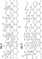
- the frame 102 (shown in a flattened configuration) in the illustrated embodiment comprises a first, lower row I of angled struts 112 arranged end-to- end and extending circumferentially at the inflow end of the frame; a second row II of circumferentially extending, angled struts 114; a third row III of circumferentially extending, angled struts 116; a fourth row IV of circumferentially extending, angled struts 118; and a fifth row V of circumferentially extending, angled struts 122 at the outflow end 105.
- a plurality of substantially straight, axially extending struts 124 can be used to interconnect the struts 112 of the first row I with the struts 114 of the second row II.
- the fifth row V of angled struts 122 are connected to the fourth row IV of angled struts 118 by a plurality of axially extending window frame portions 130 (which define the commissure windows 120) and a plurality of axially extending struts 132.
- Each commissure window frame portion 130 mounts a respective commissure of the valvular structure 104.
- each window frame portion 130 is secured at its upper and lower ends to the adjacent rows of angled struts to provide a robust configuration that enhances fatigue resistance under cyclic loading of the valve compared with known frames using cantilevered struts for supporting the commissures of the leaflet structure.
- This configuration enables a reduction in the frame wall thickness to achieve a smaller crimped diameter of the valve.
- the thickness of the frame 12 as measured between the inner diameter and outer diameter is about 0.48 mm or less.
- the struts and frame portions of the frame collectively define a plurality of open cells of the frame.
- struts 112, struts 114, and struts 134 define a lower row of cells defining openings 136.
- the second, third, and fourth rows of struts 114, 116, and 118 define two intermediate rows of cells defining openings 138.
- the fourth and fifth rows of struts 118 and 122, along with window frame portions 130 and struts 132, define an upper row of cells defining openings 140.
- the openings 140 are relatively large and are sized to allow portions of the valvular structure 104 to protrude, or bulge, into and/or through the openings 140 when the frame 102 is crimped in order to minimize the crimping profile.
- the frame can be specifically constructed to integrate window frame portions 130 and axially extending struts 132 in a 1:1 ratio.
- FIGS. 3-5 there are exactly three window frame portions 130 and exactly three axial struts 132. Minimizing or reducing the number of axially extending struts 132 between window frame portions 130 promotes more compact crimping of the prosthetic valve. This also maximizes or increases the size of openings 140, which, for example, is advantageous in cases where the outflow end 105 of the prosthetic valve extends higher than the level of the coronary ostia. In such cases, the larger openings 140 can provide access to the coronary arteries for future procedures, such as procedures requiring catheterization of the coronary arteries.
- Each window frame portion 130 and/or each axially extending strut 132 can each extend between locations 142 characterized by the convergence of the lower ends of two angled struts 122 (of row V, at the outflow end 105) to locations or nodes 144 defined by the convergence of the upper ends of two angled struts 118 (of row IV).
- the frame 102 can comprise an axially extending frame member (i.e., a frame portion 130 or a strut 132) at every other such pair of such locations 142, 144 along the rows V and VI, respectively.
- the frame 102 can have a window frame portion 130 every four such locations, and spaced equally apart around the circumference of the frame 102, which can provide for a total of three window frame portions 130 (corresponding to the three commissures in a tri-leaflet valve).
- the frame 102 can comprise, in sequence along the row V, a window frame portion 130 extending between a pair of such locations 142, 144 followed next by a second pair of locations 142, 144 lacking an axially extending strut or frame member extending therebetween, followed then by an axially extending strut 132 extending between a third pair of locations 142, 144, followed then by a fourth pair of locations 142, 144 again lacking an axially extending strut or frame member, followed by another window frame portion 130 extending between a pair of such locations 142, 144 (and thus re-starting the sequence of struts and frame portions).
- this embodiment can thus have sets of eight angled struts between adjacent window frame portions 130, along each row, with four continuous angled struts between each window frame portion 130 and its adjacent axial struts 132 ( i.e. , no other axial frame members in between).
- the prosthetic valve 100 can cycle between open and closed states to permit or restrict the flow of blood.
- the frame 102 of the prosthetic heart valve 100 provides a measure of damping during valve closure by bending inwards during diastole, which relieves stress on the leaflets. For example, forces that pull the commissures of the leaflets 110 radially inwards (such as during valve closure) can also pull areas of the frame immediately adjacent the commissures (such as the window frame portions 130) radially inward, while the axial struts 132 can be urged radially outward.
- this damping effect (including pulling of the frame portions 130 radially inward and pushing of the axial struts 132 radially outward) is enhanced by reducing the number of axial struts present along the top rungs (between rows IV and V in valve 100) as disclosed herein, relative to frames having a greater number of axial frame members (e.g., greater number of axial struts).
- the main functions of the inner skirt 106 are to assist in securing the valvular structure 104 to the frame 102 and to assist in forming a good seal between the valve 100 and the native annulus by blocking the flow of blood through the open cells of the frame 102 below the lower edge of the leaflets 110.
- the inner skirt 106 desirably comprises a tough, tear resistant material such as polyethylene terephthalate (PET), although various other synthetic or natural materials can be used.
- PET polyethylene terephthalate
- the inner skirt 106 can be secured to the inside of the frame 102 via sutures.
- the valvular structure 104 can be attached to the inner skirt 106 with the assistance of one or more thin PET reinforcing strips (which collectively can form a sleeve, not pictured), which can enable secure suturing and protect the pericardial tissue of the leaflet structure from tearing.
- the valvular structure 104 can be sandwiched between the inner skirt 106 and the thin PET strips.
- the upper edge portion of the inner skirt 106 can be formed with a plurality of projections that define an undulating shape that generally follows the shape of the fourth row of struts 118 (row IV) immediately adjacent the lower ends of axial struts 132. In this manner, as best shown in FIG. 1 , the upper edge of inner skirt 106 can be tightly secured to struts 118 with suture 146.
- the inner skirt 106 can also be secured to the first, second, and/or third rows of struts 112, 114, and 116 (rows I-III), respectively, with suture 146.
- the inner skirt 106 can be sutured to the frame 102 at locations away from the suture line attaching the lower edges of the leaflets 110 to the inner skirt 106, which both reduces concentration of stress at the leaflet-suture-line and increases pliability to the skirt in that area.
- a plurality of flexible connectors 125 can be used to interconnect each pair of adjacent edges of the leaflets 110 and to mount the leaflets 110 to the commissure window frame portions 130.
- the flexible connectors 125 can be made from a piece of woven PET fabric, although other synthetic and/or natural materials can be used.
- Each commissure can comprise two tab portions of two adjacent leaflets.
- Each commissure can be secured to the frame, for example, by inserting the tab portions through the commissure windows 120 of the window frame portions 130, and suturing the tab portions to a connector 125 outside of the frame 102.
- the outer skirt 108 can be laser cut or otherwise formed from a strong, durable piece of material, such as woven PET, although other synthetic or natural materials can be used.
- the outer skirt 108 can have a substantially straight lower edge and an upper edge defining a plurality of alternating projections 150 and notches 152.
- the lower edge of the outer skirt 108 can be sutured to the lower edge of the inner skirt 106 at the inflow end of the valve 100.
- the inner skirt 106 and outer skirt 108 are integrally manufactured as a single component. As shown in FIGS. 1-2 , each projection 150 can be affixed to the second rung II of struts 114 of the frame 102 with sutures 154.
- a frame can be constructed to have greater or fewer rows of angled struts than in frame 102, such as four or six rows of angled struts.
- each window frame portion and/or each axially extending strut can extend between two locations each defined by the convergence of the upper ends of angled struts.
- each window frame portion and/or each axially extending strut can extend between two locations each defined by the convergence of the lower ends of angled struts.
- FIG. 6 shows a perspective view of another exemplary prosthetic valve 200 with an inner skirt 206, an outer skirt 208, and a valve member 204 mounted within a stent 202.
- the valve member 204 can have a set of three leaflets 210.
- a plurality of flexible connectors 225 can be used to interconnect pairs of adjacent edges of the leaflets 210 and to mount the leaflets 210 to the commissure window frame portions 230.
- FIGS. 7-8 show perspective and flattened, unrolled views of the bare stent 202 having an inflow end 203, an outflow end 205, and four rows (I-IV) of struts 214, 216, 218, 222 (instead of five rows as shown in FIGS. 1-5 ).
- the fourth row IV of angled struts 222 can be connected to the third row IV of angled struts 218 by a plurality of axially extending window frame portions 230 (which define commissure windows 220) and a plurality of axially extending struts 232.
- each window frame portion 230 and each axially extending strut 232 can extend between the two rows of angled struts that are closest to the outflow end 205.
- each window frame portion 230 can extend between a location 242 defined by the convergence of the upper ends of two angled struts 222 and a location 244 defined by the convergence of the upper ends of two angled struts 218.
- Each axially extending strut 232 can extend between another location 246 defined by the convergence of the lower ends of two angled struts 222 and another location 248 defined by the convergence of the lower ends of two angled struts 218.
- the frame 202 can comprise three window frame portions 230 spaced equally apart around the circumference of the frame 202. As shown, the frame 202 can be constructed to have six angled struts (along each of rows III and IV) between the window frame portions 230 along each row. The frame can be constructed to have three angled struts between each window frame portion 230 and the adjacent axial struts 232. Thus, each axial strut 232 can be located halfway between adjacent window frame portions 230, and the frame 200 can be constructed to integrate window frame portions and axially extending struts in a 1:1 ratio. In the illustrated embodiment, there are exactly three window frame portions 230 and exactly three axial struts 232.
- the frame 202 can comprise, in sequence along the rows III and IV, a window frame portion 230 extending between a pair of locations 242, 244, followed by a pair of locations 246, 248 lacking an axially extending member, followed by a pair of locations 242, 244 lacking an axially extending member, followed by an axially extending strut 232 extending between a pair of locations 246, 248, followed by a pair of locations 242, 244 lacking an axially extending member, followed by a pair of locations 246, 248 lacking an axially extending member, followed by another window frame portion 230 extending between a pair of locations 242, 244 (and thus re-starting the sequence of window frame portions 230 and axially extending struts 232).
- the valve 200 can cycle between open and closed states to permit or restrict the flow of blood.
- forces that pull the commissures radially inwards during cycling can also pull the window frame portions 230 radially inward to relieve stress on the leaflets during valve closure. Meanwhile, the axial struts 232 can be urged radially outward.
- the frame 200 can be capable of assuming a collapsed configuration (such as for delivery on or within a catheter) and an expanded configuration (i.e., functional configuration at the valve annulus).
- the plurality of axial struts in the collapsed configuration, is positioned radially outwards relative to the leaflet attachment members and/or commissures.
- the valve 200 in the process of transitioning from an expanded configuration to a collapsed configuration and/or from an collapsed configuration to an expanded configuration, the valve 200 can assume an intermediate configuration in which only those struts 222 of row IV that are adjacent to an axially extending strut 232 are brought together to extend axially (side-by-side and in substantial axial alignment with struts 232).
- a frame 302 can have axial window frame members 330 extending between locations 342 defined by the convergence of the upper ends of two angled struts 322 and locations 344 defined by the convergence of the lower ends of two angled struts 318.
- the frame 302 can have axially extending struts 332 extending between locations 346 defined by the convergence of the lower ends of two angled struts 322 and locations 348 defined by the convergence of the upper ends of two angled struts 318.
- Frame 302 is similar to frame 202 except that the first three rows of angled struts (rows I, II, and III) are shifted 20 degrees relative to the same rows of frame 202.
- each window frame member 330 is axially aligned with a location 344 defined by the convergence of the lower ends of two angled struts 318 of row III.
- Each window frame member 330 can comprise a lower strut portion 334 below the level of the commissure window 320 (towards the inflow end of the stent 302).
- This lower strut portion 334 extends from the lower end of a window frame member 330 to a location 344 defined by the convergence of the lower ends of two angled struts 318.
- the lower strut portion 334 provides added length to the window frame member 330 and allows the frame member 330 to effectively bridge the larger distance between locations 342, 344 in this embodiment.
- Other features and components of frame 302 can be similar to as described above for frame 202.
- FIG. 10 shows a portion of a frame 402, according to another embodiment.
- the frame 402 can have axial window frame members 430 extending between locations 442 defined by the convergence of the lower ends of two angled struts 422 and locations 444 defined by the convergence of the lower ends of two angled struts 418.
- the frame 402 can have axially extending struts 432 extending between locations 446 defined by the convergence of the upper ends of two angled struts 422 and locations 448 defined by the convergence of the upper ends of two angled struts 418.
- the two upper rows of angled struts includes a total of three axial window frame members 430 and a total of three axially extending struts 432 located equidistant between the window frame members 430 with three angled struts 418 and three angled struts 422 extending between a window frame member 430 and an adjacent axially extending strut 432.
- the frame 402 can also include three additional rows of angled struts located at the inflow end of the frame (not shown in FIG. 10 ), similar to embodiments discussed above.
- the lower end of each window frame member 430 can be connected to the upper ends of two angled struts of an adjacent row (the third row from the outflow end of the frame) at a location 444.
- the lower end of each axially extending strut 432 is not connected to any struts of the adjacent row.
- FIG. 11 shows a portion of a frame 502, according to another embodiment.
- the frame 502 can have axial window frame members 530 extending between locations 542 defined by the convergence of the lower ends of two angled struts 552 and locations 554 defined by the convergence of the upper ends of two angled struts 518.
- the frame 502 can have axially extending struts 532 extending between locations 546 defined by the convergence of the upper ends of two angled struts 522 and locations 548 defined by the convergence of the lower ends of two angled struts 518.
- the axially extending struts 532 in this embodiment can be longer than the window frame members 530 to account for the greater distance between locations 546, 548 compared to the distance between locations 542, 544.
- the two upper rows of angled struts includes a total of three axial window frame members 530 and a total of three axially extending struts 532 located equidistant between the window frame members 530 with three angled struts 518 and three angled struts 522 extending between a window frame member 530 and an adjacent axially extending strut 532.
- the frame 502 can also include three additional rows of angled struts located at the inflow end of the frame (not shown in FIG. 11 ), similar to embodiments discussed above.
- each axially extending strut 532 can be connected to the upper ends of two angled struts of an adjacent row (the third row from the outflow end of the frame) at a location 548.
- the lower end of each window frame member 530 is not connected to any angled struts of the adjacent row.
- FIG. 12 shows a portion of a frame 602, according to another embodiment.
- the frame 602 can have axial window frame members 630 extending between locations 642 defined by the convergence of the upper ends of two angled struts 622 and locations 644 defined by the convergence of the upper ends of two angled struts 618.
- the frame 602 can have axially extending struts 632 extending between locations 646 defined by the convergence of the lower ends of two angled struts 622 and locations 648 defined by the convergence of the lower ends of two angled struts 618.
- the two upper rows of angled struts includes a total of three axial window frame members 630 and a total of six axially extending struts 632.
- the frame 602 can also include three additional rows of angled struts located at the inflow end of the frame (not shown in FIG. 12 ), similar to embodiments discussed above.
- the lower end of each axially extending strut 632 can be connected to the upper ends of two angled struts of an adjacent row (the third row from the outflow end of the frame) at a location 648.
- the lower end of each window frame member 630 is not connected to any struts of the adjacent row.
- FIG. 13 shows a portion of a frame 702, according to another embodiment.
- the frame 702 can have axial window frame members 730 extending between locations 742 defined by the convergence of the lower ends of two angled struts 722 and locations 744 defined by the convergence of the upper ends of two angled struts 718.
- the frame 702 can have axially extending struts 732 extending between locations 746 defined by the convergence of the upper ends of two angled struts 722 and locations 748 defined by the convergence of the lower ends of two angled struts 718.
- the two upper rows of angled struts includes a total of three axial window frame members 730 and a total of six axially extending struts 732.
- struts 732 can be longer than window frame members 730 to account for the greater distance between locations 746, 748 compared to the distance between locations 742, 744.
- the frame 702 can also include three additional rows of angled struts located at the inflow end of the frame (not shown in FIG. 13 ), similar to embodiments discussed above.
- the lower end of each axially extending strut 732 can be connected to the upper ends of two angled struts of an adjacent row (the third row from the outflow end of the frame) at a location 748.
- the lower end of each window frame member 730 is not connected to any struts of the adjacent row.
- the prosthetic valve embodiments disclosed herein can be surgically implanted and/or can be delivered using a delivery apparatus, such as a catheter.
- the prosthetic valve can be mounted in a crimped state on or adjacent an inflatable balloon or equivalent expansion mechanism of the delivery apparatus.
- the delivery apparatus and crimped prosthetic valve can be inserted into the patient's vasculature and advanced through the patient's body using known techniques.
- the prosthetic valve is delivered in a transfemoral procedure in which the delivery apparatus is inserted into a femoral artery and advanced through the aorta to the native aortic valve (or another native valve of the heart).
- the prosthetic valve can be delivered in a transventricular procedure in which the delivery apparatus is inserted through a small surgical opening in the chest and another surgical opening in the wall of the heart, such as the wall of the left ventricle.
- the prosthetic valve can be delivered in a transaortic procedure in which the delivery apparatus is inserted through a small surgical opening in the chest and another surgical opening in the ascending aorta, at a location above the aortic valve.
- the prosthetic valve is a replacement venous valve for implantation in a vein, or a replacement for another valve with a lower flow rate relative to the aortic valve.
- the balloon of the delivery apparatus can be inflated to radially expand the prosthetic valve.
- the outer skirt of the prosthetic valve can be forced into contact with the surrounding tissue of the native valve, establishing a seal between the outer surface of the frame and the surrounding tissue.
- the frame of the prosthetic valve when in the radially compressed, mounted configuration, can comprise an inflow end portion that has an outer diameter that is smaller than the outer diameter of the outflow end portion of the frame.
- the prosthetic valve When constructed of a self-expanding material, the prosthetic valve can be crimped to a radially compressed state and restrained in the compressed state by insertion into a sheath or equivalent mechanism of a delivery catheter. After the delivery apparatus is inserted into the body and advanced to position the prosthetic valve at the desired deployment location, the prosthetic valve can be advanced from the delivery sheath. As the prosthetic valve is deployed from the delivery sheath, the prosthetic valve can radially self-expand to its functional size.
- the prosthetic heart valve can comprise commissure portions of the leaflets extending radially outwardly through corresponding window frame portions to locations outside of the frame and sutured to the side struts of the commissure window frame.
- the window frame portions can be depressed radially inwardly relative to the surrounding portions of the frame, such as the frame portions extending between adjacent commissure windows, when the prosthetic valve is radially compressed to the collapsed configuration on a catheter.
- the commissure windows of the frame can be depressed inwardly a radial distance, such as between 0.2 mm and 1.0 mm, relative to the portions of the frame extending between adjacent commissure windows when the prosthetic valve is radially collapsed.
- the outer diameter of the outflow end portion the prosthetic valve comprising the commissure portions can be generally consistent, as opposed to the commissure portions jutting outward from the surrounding portions of the prosthetic valve, which could hinder delivery of the prosthetic valve into the body.
- the outer diameter of the inflow end portion of the frame can still be smaller than, or about equal to, the outer diameter of the outflow end portion of the frame when the prosthetic valve is radially collapsed on the catheter, allowing for a minimal or reduced maximum overall diameter of the prosthetic valve.
- the diameter of a delivery catheter through which the prosthetic valve is advanced can also be minimized or reduced. This allows the prosthetic valve to be delivered through smaller vessels in the body, making the delivery procedure less invasive, in general.
- the term “and/or” used between the last two of a list of elements means any one or more of the listed elements.
- the phrase “A, B, and/or C” means “A”, “B”, “C”, “A and B”, “A and C", “B and C”, or "A, B, and C”.
Claims (12)
- Dispositif prothétique (100 ; 200) destiné à être implanté au niveau d'un anneau de valvule cardiaque, le dispositif prothétique (100 ; 200) comprenant :un cadre annulaire (102 ; 202 ; 302) constitué d'un matériau plastiquement expansible présentant une extrémité d'entrée (103 ; 203), une extrémité de sortie (105 ; 205), au moins quatre rangées d'entretoises inclinées s'étendant de manière circonférentielle (112, 114, 116, 118, 122) et une pluralité d'éléments de cadre axiaux (330, 332, 334) pontant deux desdites au moins quatre rangées d'entretoises inclinées, la pluralité d'éléments de cadre axiaux comprenant une pluralité d'éléments de fixation de feuillet s'étendant axialement (330, 334) et une pluralité d'entretoises axiales (332) dans un rapport 1 :1,le dispositif prothétique (100 ; 200) comprenant en outre une structure de feuillet (104 ; 204) positionnée au sein du cadre (302), la structure de feuillet (104 ; 204) présentant une pluralité de commissures qui sont fixées au cadre (302) au niveau des éléments de fixation de feuillet (330),chaque élément de fixation de feuillet comprenant une partie de cadre de fenêtre (130, 230, 330) qui définit une fenêtre de commissure (120, 220, 320) etchaque élément de fixation de feuillet (130, 230, 330) et chaque entretoise axiale s'étendant uniquement entre les deux rangées d'entretoises inclinées qui sont les plus proches de l'extrémité de sortie (105, 205).
- Dispositif selon la revendication 1, le cadre étant constitué d'un matériau plastiquement expansible, en particulier d'un matériau parmi l'acier inoxydable, un alliage à base de nickel, un alliage de nickel-cobalt-chrome, un alliage de nickel-cobalt-chrome-molybdène, un alliage MP35N®, un alliage UNS R30035, un alliage de cobalt-chrome ou un polymère ; ou le cadre étant constitué d'une combinaison de deux, ou plus, de ces matériaux plastiquement expansibles mentionnés ; ou le cadre étant constitué d'un matériau auto-expansible, en particulier de nitinol.
- Dispositif selon l'une quelconque des revendications précédentes, la pluralité d'éléments de cadre axiaux comprenant exactement trois éléments de fixation de feuillet et exactement trois entretoises axiales.
- Dispositif selon l'une quelconque des revendications précédentes, les deux rangées d'entretoises inclinées (318, 322) pontées par la pluralité d'éléments de cadre axiaux (330, 332, 334) comprenant une première rangée (322) et une deuxième rangée (318), la première rangée (322) étant plus proche de l'extrémité de sortie (105 ;205) que la deuxième et que les autres rangées desdites au moins quatre rangées.
- Dispositif selon la revendication 4, la deuxième rangée comprenant quatre entretoises inclinées (118, 122) entre des éléments de cadre axiaux (130, 132) adjacents et huit entretoises inclinées (118, 122) entre des éléments de fixation de feuillet (130) adjacents.
- Dispositif selon l'une quelconque des revendications précédentes, des emplacements sélectionnés autour de la circonférence du cadre étant sans entretoises axiales.
- Dispositif selon l'une quelconque des revendications précédentes, chaque commissure comprenant deux parties de languette de deux feuillets adjacents de la structure de feuillet qui sont insérées à travers l'une respective des fenêtres de commissure (120, 220, 320).
- Dispositif selon l'une quelconque des revendications précédentes, oùlors de l'installation correcte du dispositif au niveau de l'anneau de valvule cardiaque, le dispositif est conçu pour effectuer un cycle entre des états fermé et ouvert de la structure de feuillet pour limiter ou permettre l'écoulement de sang etpendant la fermeture de la structure de feuillet, la pluralité d'entretoises axiales est positionnée radialement vers l'extérieur par rapport aux éléments de fixation de feuillet.
- Dispositif selon l'une quelconque des revendications précédentes, comprenant en outre une collerette externe fixée à une partie extérieure du cadre annulaire (302).
- Dispositif selon l'une quelconque des revendications précédentes, comprenant en outre une collerette interne fixée à une partie intérieure du cadre annulaire (302).
- Dispositif selon l'une quelconque des revendications précédentes, qui est conçu pour adopter un état radialement comprimé pour le sertissage sur un cathéter d'administration pourvu d'un ballonnet gonflable et pour adopter un état déployé lors de la dilatation du ballonnet gonflable du cathéter d'administration.
- Cathéter d'administration comprenant un ballonnet gonflable et un dispositif selon la revendication 11 monté à l'état comprimé sur le ballonnet gonflable ou à côté de celui-ci.
Applications Claiming Priority (4)
| Application Number | Priority Date | Filing Date | Title |
|---|---|---|---|
| US201461941123P | 2014-02-18 | 2014-02-18 | |
| EP21209237.3A EP4014928B1 (fr) | 2014-02-18 | 2015-02-18 | Armature à commissures souples |
| EP15752088.3A EP3107500B1 (fr) | 2014-02-18 | 2015-02-18 | Cadre à commissure flexible |
| PCT/US2015/016367 WO2015126933A1 (fr) | 2014-02-18 | 2015-02-18 | Cadre à commissure flexible |
Related Parent Applications (3)
| Application Number | Title | Priority Date | Filing Date |
|---|---|---|---|
| EP21209237.3A Division EP4014928B1 (fr) | 2014-02-18 | 2015-02-18 | Armature à commissures souples |
| EP21209237.3A Division-Into EP4014928B1 (fr) | 2014-02-18 | 2015-02-18 | Armature à commissures souples |
| EP15752088.3A Division EP3107500B1 (fr) | 2014-02-18 | 2015-02-18 | Cadre à commissure flexible |
Publications (2)
| Publication Number | Publication Date |
|---|---|
| EP4091581A1 EP4091581A1 (fr) | 2022-11-23 |
| EP4091581B1 true EP4091581B1 (fr) | 2023-12-27 |
Family
ID=53797053
Family Applications (8)
| Application Number | Title | Priority Date | Filing Date |
|---|---|---|---|
| EP22167265.2A Active EP4062874B1 (fr) | 2014-02-18 | 2015-02-18 | Armature à commissures souples |
| EP22182369.3A Pending EP4104797A1 (fr) | 2014-02-18 | 2015-02-18 | Armature à commissures souples |
| EP15752088.3A Active EP3107500B1 (fr) | 2014-02-18 | 2015-02-18 | Cadre à commissure flexible |
| EP23203298.7A Pending EP4285866A3 (fr) | 2014-02-18 | 2015-02-18 | Cadre de commissure flexible |
| EP22183861.8A Active EP4091581B1 (fr) | 2014-02-18 | 2015-02-18 | Armature à commissures souples |
| EP23201694.9A Pending EP4275656A3 (fr) | 2014-02-18 | 2015-02-18 | Cadre de commissure flexible |
| EP21209237.3A Active EP4014928B1 (fr) | 2014-02-18 | 2015-02-18 | Armature à commissures souples |
| EP23203320.9A Pending EP4285867A3 (fr) | 2014-02-18 | 2015-02-18 | Cadre de commissure flexible |
Family Applications Before (4)
| Application Number | Title | Priority Date | Filing Date |
|---|---|---|---|
| EP22167265.2A Active EP4062874B1 (fr) | 2014-02-18 | 2015-02-18 | Armature à commissures souples |
| EP22182369.3A Pending EP4104797A1 (fr) | 2014-02-18 | 2015-02-18 | Armature à commissures souples |
| EP15752088.3A Active EP3107500B1 (fr) | 2014-02-18 | 2015-02-18 | Cadre à commissure flexible |
| EP23203298.7A Pending EP4285866A3 (fr) | 2014-02-18 | 2015-02-18 | Cadre de commissure flexible |
Family Applications After (3)
| Application Number | Title | Priority Date | Filing Date |
|---|---|---|---|
| EP23201694.9A Pending EP4275656A3 (fr) | 2014-02-18 | 2015-02-18 | Cadre de commissure flexible |
| EP21209237.3A Active EP4014928B1 (fr) | 2014-02-18 | 2015-02-18 | Armature à commissures souples |
| EP23203320.9A Pending EP4285867A3 (fr) | 2014-02-18 | 2015-02-18 | Cadre de commissure flexible |
Country Status (15)
| Country | Link |
|---|---|
| US (3) | US10058420B2 (fr) |
| EP (8) | EP4062874B1 (fr) |
| JP (5) | JP6615790B2 (fr) |
| CN (2) | CN105555232B (fr) |
| CA (3) | CA3205819A1 (fr) |
| CR (1) | CR20150598A (fr) |
| DK (1) | DK3107500T3 (fr) |
| ES (2) | ES2964127T3 (fr) |
| HR (1) | HRP20211867T1 (fr) |
| HU (1) | HUE057160T2 (fr) |
| PL (2) | PL4062874T3 (fr) |
| PT (1) | PT3107500T (fr) |
| SG (1) | SG11201508887SA (fr) |
| SI (1) | SI3107500T1 (fr) |
| WO (1) | WO2015126933A1 (fr) |
Families Citing this family (47)
| Publication number | Priority date | Publication date | Assignee | Title |
|---|---|---|---|---|
| US8579964B2 (en) | 2010-05-05 | 2013-11-12 | Neovasc Inc. | Transcatheter mitral valve prosthesis |
| US9554897B2 (en) | 2011-04-28 | 2017-01-31 | Neovasc Tiara Inc. | Methods and apparatus for engaging a valve prosthesis with tissue |
| US9308087B2 (en) | 2011-04-28 | 2016-04-12 | Neovasc Tiara Inc. | Sequentially deployed transcatheter mitral valve prosthesis |
| US9345573B2 (en) | 2012-05-30 | 2016-05-24 | Neovasc Tiara Inc. | Methods and apparatus for loading a prosthesis onto a delivery system |
| WO2014124356A2 (fr) * | 2013-02-11 | 2014-08-14 | Cook Medical Technologies Llc | Cadre de support extensible et dispositif médical |
| US9572665B2 (en) | 2013-04-04 | 2017-02-21 | Neovasc Tiara Inc. | Methods and apparatus for delivering a prosthetic valve to a beating heart |
| US10433952B2 (en) | 2016-01-29 | 2019-10-08 | Neovasc Tiara Inc. | Prosthetic valve for avoiding obstruction of outflow |
| US10231829B2 (en) | 2016-05-04 | 2019-03-19 | Boston Scientific Scimed Inc. | Leaflet stitching backer |
| US9999502B2 (en) | 2016-11-04 | 2018-06-19 | Highlife Sas | Transcather valve prosthesis |
| CN113893064A (zh) | 2016-11-21 | 2022-01-07 | 内奥瓦斯克迪亚拉公司 | 用于快速收回经导管心脏瓣膜递送系统的方法和系统 |
| CN109414322B (zh) * | 2017-04-07 | 2021-05-11 | 上海甲悦医疗器械有限公司 | 一种人工瓣膜 |
| US10898319B2 (en) * | 2017-08-17 | 2021-01-26 | Edwards Lifesciences Corporation | Sealing member for prosthetic heart valve |
| CN111263622A (zh) | 2017-08-25 | 2020-06-09 | 内奥瓦斯克迪亚拉公司 | 顺序展开的经导管二尖瓣假体 |
| WO2019147846A2 (fr) | 2018-01-25 | 2019-08-01 | Edwards Lifesciences Corporation | Système de distribution pour recapture de valvule de remplacement assistée et post-déploiement de repositionnement |
| WO2019195860A2 (fr) | 2018-04-04 | 2019-10-10 | Vdyne, Llc | Dispositifs et procédés d'ancrage d'une valvule cardiaque transcathéter |
| US10595994B1 (en) | 2018-09-20 | 2020-03-24 | Vdyne, Llc | Side-delivered transcatheter heart valve replacement |
| US11344413B2 (en) | 2018-09-20 | 2022-05-31 | Vdyne, Inc. | Transcatheter deliverable prosthetic heart valves and methods of delivery |
| US11278437B2 (en) | 2018-12-08 | 2022-03-22 | Vdyne, Inc. | Compression capable annular frames for side delivery of transcatheter heart valve replacement |
| US10321995B1 (en) | 2018-09-20 | 2019-06-18 | Vdyne, Llc | Orthogonally delivered transcatheter heart valve replacement |
| US11071627B2 (en) | 2018-10-18 | 2021-07-27 | Vdyne, Inc. | Orthogonally delivered transcatheter heart valve frame for valve in valve prosthesis |
| US11109969B2 (en) | 2018-10-22 | 2021-09-07 | Vdyne, Inc. | Guidewire delivery of transcatheter heart valve |
| US11737872B2 (en) | 2018-11-08 | 2023-08-29 | Neovasc Tiara Inc. | Ventricular deployment of a transcatheter mitral valve prosthesis |
| US11253359B2 (en) | 2018-12-20 | 2022-02-22 | Vdyne, Inc. | Proximal tab for side-delivered transcatheter heart valves and methods of delivery |
| WO2020150378A1 (fr) * | 2019-01-17 | 2020-07-23 | Edwards Lifesciences Corporation | Structure pour valvule cardiaque prothétique |
| US11185409B2 (en) | 2019-01-26 | 2021-11-30 | Vdyne, Inc. | Collapsible inner flow control component for side-delivered transcatheter heart valve prosthesis |
| US11273032B2 (en) | 2019-01-26 | 2022-03-15 | Vdyne, Inc. | Collapsible inner flow control component for side-deliverable transcatheter heart valve prosthesis |
| US11648109B2 (en) * | 2019-02-04 | 2023-05-16 | Medtronic, Inc. | Balloon expandable frame for transcatheter implantation of a cardiac valve prosthesis |
| JP2022522411A (ja) | 2019-03-05 | 2022-04-19 | ブイダイン,インコーポレイテッド | 直交経カテーテルによる心臓弁プロテーゼ用の三尖弁閉鎖逆流制御装置 |
| US11173027B2 (en) | 2019-03-14 | 2021-11-16 | Vdyne, Inc. | Side-deliverable transcatheter prosthetic valves and methods for delivering and anchoring the same |
| US11076956B2 (en) | 2019-03-14 | 2021-08-03 | Vdyne, Inc. | Proximal, distal, and anterior anchoring tabs for side-delivered transcatheter mitral valve prosthesis |
| AU2020256195B2 (en) | 2019-04-01 | 2022-10-13 | Neovasc Tiara Inc. | Controllably deployable prosthetic valve |
| US11491006B2 (en) | 2019-04-10 | 2022-11-08 | Neovasc Tiara Inc. | Prosthetic valve with natural blood flow |
| WO2020227249A1 (fr) | 2019-05-04 | 2020-11-12 | Vdyne, Inc. | Dispositif cinch et procédé de déploiement d'une valvule cardiaque prothétique à pose latérale dans un anneau natif |
| WO2020236520A1 (fr) | 2019-05-17 | 2020-11-26 | Medtronic, Inc. | Endoprothèse effilée supra-annulaire extensible par ballonnet pour l'implantation transcathéter d'une prothèse de valvule cardiaque |
| CA3140925A1 (fr) | 2019-05-20 | 2020-11-26 | Neovasc Tiara Inc. | Dispositif d'introduction avec mecanisme d'hemostase |
| EP3986332A4 (fr) | 2019-06-20 | 2023-07-19 | Neovasc Tiara Inc. | Valve mitrale prothétique à profil bas |
| EP4017442A4 (fr) | 2019-08-20 | 2023-07-26 | Vdyne, Inc. | Dispositifs d'administration et de récupération et procédés pour valvules prothétiques transcathéter à pose latérale |
| AU2020337235A1 (en) | 2019-08-26 | 2022-03-24 | Vdyne, Inc. | Side-deliverable transcatheter prosthetic valves and methods for delivering and anchoring the same |
| US11234813B2 (en) | 2020-01-17 | 2022-02-01 | Vdyne, Inc. | Ventricular stability elements for side-deliverable prosthetic heart valves and methods of delivery |
| US20210275299A1 (en) * | 2020-03-04 | 2021-09-09 | Medtronic, Inc. | Devices and methods for multi-alignment of implantable medical devices |
| US20210275298A1 (en) * | 2020-03-04 | 2021-09-09 | Medtronic, Inc. | Balloon expandable stent with lengthened commissure posts for transcatheter implantation of a cardiac valve prosthesis |
| US20230248513A1 (en) * | 2020-07-07 | 2023-08-10 | Anteris Technologies Corporation | Expandable frame for improved hemodynamic performance of transcatheter replacement heart valve |
| EP4185244A4 (fr) * | 2020-07-23 | 2024-03-27 | St Jude Medical Cardiology Div Inc | Valve cardiaque extensible à profil bas |
| CN114469446A (zh) * | 2020-11-13 | 2022-05-13 | 上海微创心通医疗科技有限公司 | 瓣膜支架和瓣膜假体 |
| WO2023009379A1 (fr) * | 2021-07-28 | 2023-02-02 | Edwards Lifesciences Corporation | Armatures de valvules cardiaques prothétiques à parties de commissure radialement décalées |
| WO2023086650A1 (fr) * | 2021-11-15 | 2023-05-19 | Edwards Lifesciences Corporation | Valves prothétiques à cellules d'évacuation plus larges |
| JP2023127496A (ja) | 2022-03-01 | 2023-09-13 | 株式会社デンソー | 回転電機の固定子 |
Citations (1)
| Publication number | Priority date | Publication date | Assignee | Title |
|---|---|---|---|---|
| CN103550015A (zh) * | 2013-11-01 | 2014-02-05 | 金仕生物科技(常熟)有限公司 | 一种人工心脏瓣膜瓣架和采用此瓣架的介入人工心脏瓣膜 |
Family Cites Families (126)
| Publication number | Priority date | Publication date | Assignee | Title |
|---|---|---|---|---|
| US3755823A (en) | 1971-04-23 | 1973-09-04 | Hancock Laboratories Inc | Flexible stent for heart valve |
| US4035849A (en) | 1975-11-17 | 1977-07-19 | William W. Angell | Heart valve stent and process for preparing a stented heart valve prosthesis |
| IT1212547B (it) | 1982-08-09 | 1989-11-30 | Iorio Domenico | Strumento di impiego chirurgico destinato a rendere piu' facili e piu' sicuri gli interventi per l'impianto di bioprotesi in organi umani |
| US4787899A (en) | 1983-12-09 | 1988-11-29 | Lazarus Harrison M | Intraluminal graft device, system and method |
| SU1271508A1 (ru) | 1984-11-29 | 1986-11-23 | Горьковский государственный медицинский институт им.С.М.Кирова | Искусственный клапан сердца |
| US4777951A (en) | 1986-09-19 | 1988-10-18 | Mansfield Scientific, Inc. | Procedure and catheter instrument for treating patients for aortic stenosis |
| US4878495A (en) | 1987-05-15 | 1989-11-07 | Joseph Grayzel | Valvuloplasty device with satellite expansion means |
| US4796629A (en) | 1987-06-03 | 1989-01-10 | Joseph Grayzel | Stiffened dilation balloon catheter device |
| US4856516A (en) | 1989-01-09 | 1989-08-15 | Cordis Corporation | Endovascular stent apparatus and method |
| US4966604A (en) | 1989-01-23 | 1990-10-30 | Interventional Technologies Inc. | Expandable atherectomy cutter with flexibly bowed blades |
| US4994077A (en) | 1989-04-21 | 1991-02-19 | Dobben Richard L | Artificial heart valve for implantation in a blood vessel |
| US5059177A (en) | 1990-04-19 | 1991-10-22 | Cordis Corporation | Triple lumen balloon catheter |
| US5411552A (en) | 1990-05-18 | 1995-05-02 | Andersen; Henning R. | Valve prothesis for implantation in the body and a catheter for implanting such valve prothesis |
| DK124690D0 (da) | 1990-05-18 | 1990-05-18 | Henning Rud Andersen | Klapprotes til implantering i kroppen for erstatning af naturlig klap samt kateter til brug ved implantering af en saadan klapprotese |
| US5282847A (en) | 1991-02-28 | 1994-02-01 | Medtronic, Inc. | Prosthetic vascular grafts with a pleated structure |
| US5769812A (en) | 1991-07-16 | 1998-06-23 | Heartport, Inc. | System for cardiac procedures |
| US5370685A (en) | 1991-07-16 | 1994-12-06 | Stanford Surgical Technologies, Inc. | Endovascular aortic valve replacement |
| US5584803A (en) | 1991-07-16 | 1996-12-17 | Heartport, Inc. | System for cardiac procedures |
| US5558644A (en) | 1991-07-16 | 1996-09-24 | Heartport, Inc. | Retrograde delivery catheter and method for inducing cardioplegic arrest |
| US5192297A (en) | 1991-12-31 | 1993-03-09 | Medtronic, Inc. | Apparatus and method for placement and implantation of a stent |
| US5683448A (en) | 1992-02-21 | 1997-11-04 | Boston Scientific Technology, Inc. | Intraluminal stent and graft |
| US6346074B1 (en) | 1993-02-22 | 2002-02-12 | Heartport, Inc. | Devices for less invasive intracardiac interventions |
| CA2125258C (fr) | 1993-08-05 | 1998-12-22 | Dinah B Quiachon | Systeme de greffe intraluminale multicapsulaire et methode |
| US5609627A (en) | 1994-02-09 | 1997-03-11 | Boston Scientific Technology, Inc. | Method for delivering a bifurcated endoluminal prosthesis |
| US5554185A (en) | 1994-07-18 | 1996-09-10 | Block; Peter C. | Inflatable prosthetic cardiovascular valve for percutaneous transluminal implantation of same |
| DE19532846A1 (de) | 1995-09-06 | 1997-03-13 | Georg Dr Berg | Ventileinrichtung |
| US5591195A (en) | 1995-10-30 | 1997-01-07 | Taheri; Syde | Apparatus and method for engrafting a blood vessel |
| DE19546692C2 (de) | 1995-12-14 | 2002-11-07 | Hans-Reiner Figulla | Selbstexpandierende Herzklappenprothese zur Implantation im menschlichen Körper über ein Kathetersystem |
| DE69719237T2 (de) | 1996-05-23 | 2003-11-27 | Samsung Electronics Co Ltd | Flexibler, selbstexpandierbarer Stent und Verfahren zu dessen Herstellung |
| EP0850607A1 (fr) | 1996-12-31 | 1998-07-01 | Cordis Corporation | Prothèse de valve pour implantation dans des canaux corporels |
| US5855597A (en) | 1997-05-07 | 1999-01-05 | Iowa-India Investments Co. Limited | Stent valve and stent graft for percutaneous surgery |
| US6245102B1 (en) | 1997-05-07 | 2001-06-12 | Iowa-India Investments Company Ltd. | Stent, stent graft and stent valve |
| US5925063A (en) | 1997-09-26 | 1999-07-20 | Khosravi; Farhad | Coiled sheet valve, filter or occlusive device and methods of use |
| EP0935978A1 (fr) | 1998-02-16 | 1999-08-18 | Medicorp S.A. | Cathéter d'angioplastie et de mise en place d'un stent |
| EP0943300A1 (fr) | 1998-03-17 | 1999-09-22 | Medicorp S.A. | Dispositif pour la mise en place d'un stent de manière réversible |
| US6527979B2 (en) | 1999-08-27 | 2003-03-04 | Corazon Technologies, Inc. | Catheter systems and methods for their use in the treatment of calcified vascular occlusions |
| DE19857887B4 (de) | 1998-12-15 | 2005-05-04 | Fraunhofer-Gesellschaft zur Förderung der angewandten Forschung e.V. | Verankerungsstütze für eine Herzklappenprothese |
| FR2788217A1 (fr) | 1999-01-12 | 2000-07-13 | Brice Letac | Valvule prothetique implantable par catheterisme, ou chirurgicalement |
| US6425916B1 (en) | 1999-02-10 | 2002-07-30 | Michi E. Garrison | Methods and devices for implanting cardiac valves |
| DE19907646A1 (de) | 1999-02-23 | 2000-08-24 | Georg Berg | Ventileinrichtung zum Einsetzen in ein Hohlorgan |
| FR2800984B1 (fr) | 1999-11-17 | 2001-12-14 | Jacques Seguin | Dispositif de remplacement d'une valve cardiaque par voie percutanee |
| US7018406B2 (en) | 1999-11-17 | 2006-03-28 | Corevalve Sa | Prosthetic valve for transluminal delivery |
| FR2815844B1 (fr) | 2000-10-31 | 2003-01-17 | Jacques Seguin | Support tubulaire de mise en place, par voie percutanee, d'une valve cardiaque de remplacement |
| US6458153B1 (en) | 1999-12-31 | 2002-10-01 | Abps Venture One, Ltd. | Endoluminal cardiac and venous valve prostheses and methods of manufacture and delivery thereof |
| ES2286097T7 (es) | 2000-01-31 | 2009-11-05 | Cook Biotech, Inc | Valvulas de endoprotesis. |
| US20050267560A1 (en) * | 2000-02-03 | 2005-12-01 | Cook Incorporated | Implantable bioabsorbable valve support frame |
| DE10010074B4 (de) | 2000-02-28 | 2005-04-14 | Fraunhofer-Gesellschaft zur Förderung der angewandten Forschung e.V. | Vorrichtung zur Befestigung und Verankerung von Herzklappenprothesen |
| DE10010073B4 (de) | 2000-02-28 | 2005-12-22 | Fraunhofer-Gesellschaft zur Förderung der angewandten Forschung e.V. | Verankerung für implantierbare Herzklappenprothesen |
| US6454799B1 (en) | 2000-04-06 | 2002-09-24 | Edwards Lifesciences Corporation | Minimally-invasive heart valves and methods of use |
| US7510572B2 (en) | 2000-09-12 | 2009-03-31 | Shlomo Gabbay | Implantation system for delivery of a heart valve prosthesis |
| WO2002022054A1 (fr) | 2000-09-12 | 2002-03-21 | Gabbay S | Prothese valvulaire et son procede d'utilisation |
| US6461382B1 (en) | 2000-09-22 | 2002-10-08 | Edwards Lifesciences Corporation | Flexible heart valve having moveable commissures |
| US6482228B1 (en) | 2000-11-14 | 2002-11-19 | Troy R. Norred | Percutaneous aortic valve replacement |
| US20040093075A1 (en) | 2000-12-15 | 2004-05-13 | Titus Kuehne | Stent with valve and method of use thereof |
| US6503272B2 (en) | 2001-03-21 | 2003-01-07 | Cordis Corporation | Stent-based venous valves |
| US6733525B2 (en) | 2001-03-23 | 2004-05-11 | Edwards Lifesciences Corporation | Rolled minimally-invasive heart valves and methods of use |
| US7556646B2 (en) | 2001-09-13 | 2009-07-07 | Edwards Lifesciences Corporation | Methods and apparatuses for deploying minimally-invasive heart valves |
| US7374571B2 (en) | 2001-03-23 | 2008-05-20 | Edwards Lifesciences Corporation | Rolled minimally-invasive heart valves and methods of manufacture |
| US6893460B2 (en) | 2001-10-11 | 2005-05-17 | Percutaneous Valve Technologies Inc. | Implantable prosthetic valve |
| WO2003043676A2 (fr) | 2001-11-23 | 2003-05-30 | Mindguard Ltd. | Appareil de positionnement extensible servant en particulier a mettre en place des dispositifs intravasculaires |
| US7141064B2 (en) | 2002-05-08 | 2006-11-28 | Edwards Lifesciences Corporation | Compressed tissue for heart valve leaflets |
| US6878162B2 (en) | 2002-08-30 | 2005-04-12 | Edwards Lifesciences Ag | Helical stent having improved flexibility and expandability |
| US7137184B2 (en) | 2002-09-20 | 2006-11-21 | Edwards Lifesciences Corporation | Continuous heart valve support frame and method of manufacture |
| US20100003253A1 (en) | 2002-11-08 | 2010-01-07 | Ablynx N.V. | Single domain antibodies directed against epidermal growth factor receptor and uses therefor |
| US7399315B2 (en) | 2003-03-18 | 2008-07-15 | Edwards Lifescience Corporation | Minimally-invasive heart valve with cusp positioners |
| US8221492B2 (en) | 2003-04-24 | 2012-07-17 | Cook Medical Technologies | Artificial valve prosthesis with improved flow dynamics |
| JP2006526464A (ja) | 2003-06-05 | 2006-11-24 | フローメディカ,インコーポレイテッド | 分枝した身体管腔において両側介入または診断を行うためのシステムおよび方法 |
| US20050075725A1 (en) | 2003-10-02 | 2005-04-07 | Rowe Stanton J. | Implantable prosthetic valve with non-laminar flow |
| US20050075713A1 (en) * | 2003-10-06 | 2005-04-07 | Brian Biancucci | Minimally invasive valve replacement system |
| DE10352874B4 (de) | 2003-11-10 | 2008-03-27 | Qualimed Innovative Medizinprodukte Gmbh | Stent |
| US7258697B1 (en) | 2003-12-22 | 2007-08-21 | Advanced Cardiovascular Systems, Inc. | Stent with anchors to prevent vulnerable plaque rupture during deployment |
| US8182528B2 (en) | 2003-12-23 | 2012-05-22 | Sadra Medical, Inc. | Locking heart valve anchor |
| US8828078B2 (en) | 2003-12-23 | 2014-09-09 | Sadra Medical, Inc. | Methods and apparatus for endovascular heart valve replacement comprising tissue grasping elements |
| US7959666B2 (en) | 2003-12-23 | 2011-06-14 | Sadra Medical, Inc. | Methods and apparatus for endovascularly replacing a heart valve |
| WO2005076973A2 (fr) | 2004-02-05 | 2005-08-25 | Children's Medical Center Corporation | Apport par catheter d'une valvule cardiaque de remplacement |
| WO2005084595A1 (fr) | 2004-02-27 | 2005-09-15 | Cardiacmd, Inc. | Systemes et procedes de mise en place de valvules cardiaques prothetiques |
| AU2005234793B2 (en) | 2004-04-23 | 2012-01-19 | 3F Therapeutics, Inc. | Implantable prosthetic valve |
| US20060095115A1 (en) * | 2004-05-10 | 2006-05-04 | Youssef Bladillah | Stent and method of manufacturing same |
| US20060122693A1 (en) | 2004-05-10 | 2006-06-08 | Youssef Biadillah | Stent valve and method of manufacturing same |
| US20060122692A1 (en) * | 2004-05-10 | 2006-06-08 | Ran Gilad | Stent valve and method of using same |
| US7462191B2 (en) | 2004-06-30 | 2008-12-09 | Edwards Lifesciences Pvt, Inc. | Device and method for assisting in the implantation of a prosthetic valve |
| US7276078B2 (en) | 2004-06-30 | 2007-10-02 | Edwards Lifesciences Pvt | Paravalvular leak detection, sealing, and prevention |
| AU2005284739B2 (en) | 2004-09-14 | 2011-02-24 | Edwards Lifesciences Ag | Device and method for treatment of heart valve regurgitation |
| ITTO20050074A1 (it) * | 2005-02-10 | 2006-08-11 | Sorin Biomedica Cardio Srl | Protesi valvola cardiaca |
| SE531468C2 (sv) | 2005-04-21 | 2009-04-14 | Edwards Lifesciences Ag | En anordning för styrning av blodflöde |
| US8500798B2 (en) | 2005-05-24 | 2013-08-06 | Edwards Lifesciences Corporation | Rapid deployment prosthetic heart valve |
| US7780723B2 (en) | 2005-06-13 | 2010-08-24 | Edwards Lifesciences Corporation | Heart valve delivery system |
| US20080058856A1 (en) | 2005-06-28 | 2008-03-06 | Venkatesh Ramaiah | Non-occluding dilation device |
| US8167932B2 (en) | 2005-10-18 | 2012-05-01 | Edwards Lifesciences Corporation | Heart valve delivery system with valve catheter |
| US8778017B2 (en) | 2005-10-26 | 2014-07-15 | Cardiosolutions, Inc. | Safety for mitral valve implant |
| US7785366B2 (en) | 2005-10-26 | 2010-08-31 | Maurer Christopher W | Mitral spacer |
| US8449606B2 (en) | 2005-10-26 | 2013-05-28 | Cardiosolutions, Inc. | Balloon mitral spacer |
| US8764820B2 (en) | 2005-11-16 | 2014-07-01 | Edwards Lifesciences Corporation | Transapical heart valve delivery system and method |
| CA2631662C (fr) | 2005-12-07 | 2014-08-05 | Arbor Surgical Technologies, Inc. | Systemes de connexion pour ensembles valve cardiaque prosthetique en deux parties |
| EP1988851A2 (fr) | 2006-02-14 | 2008-11-12 | Sadra Medical, Inc. | Systemes et procedes pour installer un implant medical |
| US8147541B2 (en) | 2006-02-27 | 2012-04-03 | Aortx, Inc. | Methods and devices for delivery of prosthetic heart valves and other prosthetics |
| EP2020958B1 (fr) | 2006-05-30 | 2012-05-30 | Cook Medical Technologies LLC | Prothèse de valve artificielle |
| US8029556B2 (en) | 2006-10-04 | 2011-10-04 | Edwards Lifesciences Corporation | Method and apparatus for reshaping a ventricle |
| US7655034B2 (en) | 2006-11-14 | 2010-02-02 | Medtronic Vascular, Inc. | Stent-graft with anchoring pins |
| US8133270B2 (en) * | 2007-01-08 | 2012-03-13 | California Institute Of Technology | In-situ formation of a valve |
| US9510943B2 (en) | 2007-01-19 | 2016-12-06 | Medtronic, Inc. | Stented heart valve devices and methods for atrioventricular valve replacement |
| DE102007043830A1 (de) | 2007-09-13 | 2009-04-02 | Lozonschi, Lucian, Madison | Herzklappenstent |
| EP3245980B1 (fr) | 2007-09-26 | 2022-07-20 | St. Jude Medical, LLC | Valvules cardiaques prothétiques repliables |
| HUE056405T2 (hu) | 2007-12-14 | 2022-02-28 | Edwards Lifesciences Corp | Vitorlarögzítõ keret egy billentyûprotézishez |
| EP3572044B1 (fr) * | 2008-01-24 | 2021-07-28 | Medtronic, Inc. | Stents pour des valvules cardiaques prothétiques |
| US20090276040A1 (en) | 2008-05-01 | 2009-11-05 | Edwards Lifesciences Corporation | Device and method for replacing mitral valve |
| US9061119B2 (en) | 2008-05-09 | 2015-06-23 | Edwards Lifesciences Corporation | Low profile delivery system for transcatheter heart valve |
| ATE554731T1 (de) * | 2008-05-16 | 2012-05-15 | Sorin Biomedica Cardio Srl | Atraumatische prothetische herzklappenprothese |
| DK3653173T3 (da) | 2008-06-06 | 2021-05-03 | Edwards Lifesciences Corp | Transkateterhjerteklap med lav profil |
| US8323335B2 (en) | 2008-06-20 | 2012-12-04 | Edwards Lifesciences Corporation | Retaining mechanisms for prosthetic valves and methods for using |
| EP3878408A1 (fr) | 2008-07-21 | 2021-09-15 | Jenesis Surgical, LLC | Appareil de support endoluminal |
| US8652202B2 (en) | 2008-08-22 | 2014-02-18 | Edwards Lifesciences Corporation | Prosthetic heart valve and delivery apparatus |
| EP2367505B1 (fr) * | 2008-09-29 | 2020-08-12 | Edwards Lifesciences CardiAQ LLC | Valvule cardiaque |
| EP2419050B2 (fr) | 2009-04-15 | 2023-10-18 | Edwards Lifesciences CardiAQ LLC | Implant vasculaire et système d'introduction |
| EP2437689B1 (fr) | 2009-06-05 | 2023-08-02 | Medtronic ATS Medical Inc. | Structure a commissure flexible servant a fixer une bioprothese de valvule |
| US8439970B2 (en) | 2009-07-14 | 2013-05-14 | Edwards Lifesciences Corporation | Transapical delivery system for heart valves |
| WO2011025896A1 (fr) | 2009-08-26 | 2011-03-03 | Coalstar Industries, Inc. | Appareil et procédés de fabrication dhuiles dérivées du charbon |
| LT3669829T (lt) | 2010-10-05 | 2021-10-25 | Edwards Lifesciences Corporation | Protezinis širdies vožtuvas |
| US20120172980A1 (en) * | 2011-01-05 | 2012-07-05 | Curia, Inc. | Kits with prosthetic valves formed with isotropic filter screen leaflets and methods thereof |
| US8888843B2 (en) | 2011-01-28 | 2014-11-18 | Middle Peak Medical, Inc. | Device, system, and method for transcatheter treatment of valve regurgitation |
| US9717593B2 (en) * | 2011-02-01 | 2017-08-01 | St. Jude Medical, Cardiology Division, Inc. | Leaflet suturing to commissure points for prosthetic heart valve |
| US20130023984A1 (en) * | 2011-07-20 | 2013-01-24 | Edwards Lifesciences Corporation | Commissure modification of prosthetic heart valve frame for improved leaflet attachment |
| US9039757B2 (en) | 2011-10-19 | 2015-05-26 | Twelve, Inc. | Prosthetic heart valve devices, prosthetic mitral valves and associated systems and methods |
| WO2013155474A1 (fr) * | 2012-04-12 | 2013-10-17 | California Institute Of Technology | Systèmes de mise en place percutanée de valvule cardiaque |
| US10039638B2 (en) * | 2012-12-19 | 2018-08-07 | W. L. Gore & Associates, Inc. | Geometric prosthetic heart valves |
| US9326856B2 (en) * | 2013-03-14 | 2016-05-03 | St. Jude Medical, Cardiology Division, Inc. | Cuff configurations for prosthetic heart valve |
-
2015
- 2015-02-18 HU HUE15752088A patent/HUE057160T2/hu unknown
- 2015-02-18 EP EP22167265.2A patent/EP4062874B1/fr active Active
- 2015-02-18 CN CN201580001526.4A patent/CN105555232B/zh active Active
- 2015-02-18 EP EP22182369.3A patent/EP4104797A1/fr active Pending
- 2015-02-18 EP EP15752088.3A patent/EP3107500B1/fr active Active
- 2015-02-18 ES ES21209237T patent/ES2964127T3/es active Active
- 2015-02-18 DK DK15752088.3T patent/DK3107500T3/da active
- 2015-02-18 EP EP23203298.7A patent/EP4285866A3/fr active Pending
- 2015-02-18 SI SI201531765T patent/SI3107500T1/sl unknown
- 2015-02-18 EP EP22183861.8A patent/EP4091581B1/fr active Active
- 2015-02-18 ES ES15752088T patent/ES2900857T3/es active Active
- 2015-02-18 CA CA3205819A patent/CA3205819A1/en active Pending
- 2015-02-18 HR HRP20211867TT patent/HRP20211867T1/hr unknown
- 2015-02-18 JP JP2016569582A patent/JP6615790B2/ja active Active
- 2015-02-18 US US14/625,344 patent/US10058420B2/en active Active
- 2015-02-18 PT PT157520883T patent/PT3107500T/pt unknown
- 2015-02-18 SG SG11201508887SA patent/SG11201508887SA/en unknown
- 2015-02-18 WO PCT/US2015/016367 patent/WO2015126933A1/fr active Application Filing
- 2015-02-18 CA CA3153863A patent/CA3153863C/fr active Active
- 2015-02-18 CA CA2910087A patent/CA2910087C/fr active Active
- 2015-02-18 EP EP23201694.9A patent/EP4275656A3/fr active Pending
- 2015-02-18 PL PL22167265.2T patent/PL4062874T3/pl unknown
- 2015-02-18 EP EP21209237.3A patent/EP4014928B1/fr active Active
- 2015-02-18 CN CN201911323089.4A patent/CN110934666B/zh active Active
- 2015-02-18 PL PL15752088T patent/PL3107500T3/pl unknown
- 2015-02-18 EP EP23203320.9A patent/EP4285867A3/fr active Pending
- 2015-11-02 CR CR20150598A patent/CR20150598A/es unknown
-
2018
- 2018-08-24 US US16/112,556 patent/US11432923B2/en active Active
-
2019
- 2019-11-05 JP JP2019200980A patent/JP6992034B2/ja active Active
-
2021
- 2021-12-08 JP JP2021199320A patent/JP7358443B2/ja active Active
-
2022
- 2022-03-28 US US17/706,419 patent/US20220218470A1/en active Pending
- 2022-07-28 JP JP2022120636A patent/JP7439183B2/ja active Active
- 2022-07-28 JP JP2022120637A patent/JP7439184B2/ja active Active
Patent Citations (1)
| Publication number | Priority date | Publication date | Assignee | Title |
|---|---|---|---|---|
| CN103550015A (zh) * | 2013-11-01 | 2014-02-05 | 金仕生物科技(常熟)有限公司 | 一种人工心脏瓣膜瓣架和采用此瓣架的介入人工心脏瓣膜 |
Also Published As
Similar Documents
| Publication | Publication Date | Title |
|---|---|---|
| US11432923B2 (en) | Flexible commissure frame | |
| CN106999273B (zh) | 具有无支撑瓣膜区段的分段式经导管瓣膜假体 | |
| EP3082656B1 (fr) | Valve prothétique à feuillet inversé | |
| US11484406B2 (en) | Prosthetic heart valve having leaflet inflow below frame | |
| US11957574B2 (en) | Flexible commissure frame | |
| JP2024052774A (ja) | 可撓性交連フレーム | |
| JP2024052775A (ja) | 可撓性交連フレーム |
Legal Events
| Date | Code | Title | Description |
|---|---|---|---|
| PUAI | Public reference made under article 153(3) epc to a published international application that has entered the european phase |
Free format text: ORIGINAL CODE: 0009012 |
|
| STAA | Information on the status of an ep patent application or granted ep patent |
Free format text: STATUS: REQUEST FOR EXAMINATION WAS MADE |
|
| 17P | Request for examination filed |
Effective date: 20220708 |
|
| AC | Divisional application: reference to earlier application |
Ref document number: 3107500 Country of ref document: EP Kind code of ref document: P Ref document number: 4014928 Country of ref document: EP Kind code of ref document: P |
|
| AK | Designated contracting states |
Kind code of ref document: A1 Designated state(s): AL AT BE BG CH CY CZ DE DK EE ES FI FR GB GR HR HU IE IS IT LI LT LU LV MC MK MT NL NO PL PT RO RS SE SI SK SM TR |
|
| GRAP | Despatch of communication of intention to grant a patent |
Free format text: ORIGINAL CODE: EPIDOSNIGR1 |
|
| STAA | Information on the status of an ep patent application or granted ep patent |
Free format text: STATUS: GRANT OF PATENT IS INTENDED |
|
| INTG | Intention to grant announced |
Effective date: 20230315 |
|
| RIN1 | Information on inventor provided before grant (corrected) |
Inventor name: LEVI, TAMIR S. |
|
| GRAJ | Information related to disapproval of communication of intention to grant by the applicant or resumption of examination proceedings by the epo deleted |
Free format text: ORIGINAL CODE: EPIDOSDIGR1 |
|
| STAA | Information on the status of an ep patent application or granted ep patent |
Free format text: STATUS: REQUEST FOR EXAMINATION WAS MADE |
|
| GRAP | Despatch of communication of intention to grant a patent |
Free format text: ORIGINAL CODE: EPIDOSNIGR1 |
|
| INTC | Intention to grant announced (deleted) | ||
| STAA | Information on the status of an ep patent application or granted ep patent |
Free format text: STATUS: GRANT OF PATENT IS INTENDED |
|
| INTG | Intention to grant announced |
Effective date: 20230713 |
|
| P01 | Opt-out of the competence of the unified patent court (upc) registered |
Effective date: 20230821 |
|
| GRAS | Grant fee paid |
Free format text: ORIGINAL CODE: EPIDOSNIGR3 |
|
| GRAA | (expected) grant |
Free format text: ORIGINAL CODE: 0009210 |
|
| STAA | Information on the status of an ep patent application or granted ep patent |
Free format text: STATUS: THE PATENT HAS BEEN GRANTED |
|
| AC | Divisional application: reference to earlier application |
Ref document number: 3107500 Country of ref document: EP Kind code of ref document: P Ref document number: 4014928 Country of ref document: EP Kind code of ref document: P |
|
| AK | Designated contracting states |
Kind code of ref document: B1 Designated state(s): AL AT BE BG CH CY CZ DE DK EE ES FI FR GB GR HR HU IE IS IT LI LT LU LV MC MK MT NL NO PL PT RO RS SE SI SK SM TR |
|
| REG | Reference to a national code |
Ref country code: GB Ref legal event code: FG4D |
|
| REG | Reference to a national code |
Ref country code: CH Ref legal event code: EP |
|
| REG | Reference to a national code |
Ref country code: DE Ref legal event code: R096 Ref document number: 602015087127 Country of ref document: DE |
|
| REG | Reference to a national code |
Ref country code: IE Ref legal event code: FG4D |
|
| U01 | Request for unitary effect filed |
Effective date: 20240129 |
|
| REG | Reference to a national code |
Ref country code: NL Ref legal event code: FP |
|
| PG25 | Lapsed in a contracting state [announced via postgrant information from national office to epo] |
Ref country code: GR Free format text: LAPSE BECAUSE OF FAILURE TO SUBMIT A TRANSLATION OF THE DESCRIPTION OR TO PAY THE FEE WITHIN THE PRESCRIBED TIME-LIMIT Effective date: 20240328 |
|
| REG | Reference to a national code |
Ref country code: LT Ref legal event code: MG9D |