EP4089285B1 - Umkehrlüfter - Google Patents
Umkehrlüfter Download PDFInfo
- Publication number
- EP4089285B1 EP4089285B1 EP22169808.7A EP22169808A EP4089285B1 EP 4089285 B1 EP4089285 B1 EP 4089285B1 EP 22169808 A EP22169808 A EP 22169808A EP 4089285 B1 EP4089285 B1 EP 4089285B1
- Authority
- EP
- European Patent Office
- Prior art keywords
- spoke
- motor
- rotation axis
- impeller
- fan
- Prior art date
- Legal status (The legal status is an assumption and is not a legal conclusion. Google has not performed a legal analysis and makes no representation as to the accuracy of the status listed.)
- Active
Links
Images


Classifications
-
- F—MECHANICAL ENGINEERING; LIGHTING; HEATING; WEAPONS; BLASTING
- F04—POSITIVE - DISPLACEMENT MACHINES FOR LIQUIDS; PUMPS FOR LIQUIDS OR ELASTIC FLUIDS
- F04D—NON-POSITIVE-DISPLACEMENT PUMPS
- F04D19/00—Axial-flow pumps
- F04D19/002—Axial flow fans
- F04D19/005—Axial flow fans reversible fans
-
- F—MECHANICAL ENGINEERING; LIGHTING; HEATING; WEAPONS; BLASTING
- F04—POSITIVE - DISPLACEMENT MACHINES FOR LIQUIDS; PUMPS FOR LIQUIDS OR ELASTIC FLUIDS
- F04D—NON-POSITIVE-DISPLACEMENT PUMPS
- F04D25/00—Pumping installations or systems
- F04D25/02—Units comprising pumps and their driving means
- F04D25/06—Units comprising pumps and their driving means the pump being electrically driven
- F04D25/0693—Details or arrangements of the wiring
-
- F—MECHANICAL ENGINEERING; LIGHTING; HEATING; WEAPONS; BLASTING
- F04—POSITIVE - DISPLACEMENT MACHINES FOR LIQUIDS; PUMPS FOR LIQUIDS OR ELASTIC FLUIDS
- F04D—NON-POSITIVE-DISPLACEMENT PUMPS
- F04D25/00—Pumping installations or systems
- F04D25/02—Units comprising pumps and their driving means
- F04D25/08—Units comprising pumps and their driving means the working fluid being air, e.g. for ventilation
-
- F—MECHANICAL ENGINEERING; LIGHTING; HEATING; WEAPONS; BLASTING
- F04—POSITIVE - DISPLACEMENT MACHINES FOR LIQUIDS; PUMPS FOR LIQUIDS OR ELASTIC FLUIDS
- F04D—NON-POSITIVE-DISPLACEMENT PUMPS
- F04D29/00—Details, component parts, or accessories
- F04D29/40—Casings; Connections of working fluid
- F04D29/52—Casings; Connections of working fluid for axial pumps
- F04D29/54—Fluid-guiding means, e.g. diffusers
- F04D29/541—Specially adapted for elastic fluid pumps
- F04D29/542—Bladed diffusers
- F04D29/544—Blade shapes
-
- F—MECHANICAL ENGINEERING; LIGHTING; HEATING; WEAPONS; BLASTING
- F04—POSITIVE - DISPLACEMENT MACHINES FOR LIQUIDS; PUMPS FOR LIQUIDS OR ELASTIC FLUIDS
- F04D—NON-POSITIVE-DISPLACEMENT PUMPS
- F04D29/00—Details, component parts, or accessories
- F04D29/40—Casings; Connections of working fluid
- F04D29/52—Casings; Connections of working fluid for axial pumps
- F04D29/54—Fluid-guiding means, e.g. diffusers
- F04D29/541—Specially adapted for elastic fluid pumps
- F04D29/545—Ducts
- F04D29/547—Ducts having a special shape in order to influence fluid flow
-
- F—MECHANICAL ENGINEERING; LIGHTING; HEATING; WEAPONS; BLASTING
- F04—POSITIVE - DISPLACEMENT MACHINES FOR LIQUIDS; PUMPS FOR LIQUIDS OR ELASTIC FLUIDS
- F04D—NON-POSITIVE-DISPLACEMENT PUMPS
- F04D29/00—Details, component parts, or accessories
- F04D29/60—Mounting; Assembling; Disassembling
- F04D29/64—Mounting; Assembling; Disassembling of axial pumps
- F04D29/644—Mounting; Assembling; Disassembling of axial pumps especially adapted for elastic fluid pumps
- F04D29/646—Mounting or removal of fans
-
- F—MECHANICAL ENGINEERING; LIGHTING; HEATING; WEAPONS; BLASTING
- F04—POSITIVE - DISPLACEMENT MACHINES FOR LIQUIDS; PUMPS FOR LIQUIDS OR ELASTIC FLUIDS
- F04D—NON-POSITIVE-DISPLACEMENT PUMPS
- F04D29/00—Details, component parts, or accessories
- F04D29/66—Combating cavitation, whirls, noise, vibration or the like; Balancing
- F04D29/661—Combating cavitation, whirls, noise, vibration or the like; Balancing especially adapted for elastic fluid pumps
-
- F—MECHANICAL ENGINEERING; LIGHTING; HEATING; WEAPONS; BLASTING
- F04—POSITIVE - DISPLACEMENT MACHINES FOR LIQUIDS; PUMPS FOR LIQUIDS OR ELASTIC FLUIDS
- F04D—NON-POSITIVE-DISPLACEMENT PUMPS
- F04D29/00—Details, component parts, or accessories
- F04D29/66—Combating cavitation, whirls, noise, vibration or the like; Balancing
- F04D29/661—Combating cavitation, whirls, noise, vibration or the like; Balancing especially adapted for elastic fluid pumps
- F04D29/667—Combating cavitation, whirls, noise, vibration or the like; Balancing especially adapted for elastic fluid pumps by influencing the flow pattern, e.g. suppression of turbulence
-
- H—ELECTRICITY
- H02—GENERATION; CONVERSION OR DISTRIBUTION OF ELECTRIC POWER
- H02K—DYNAMO-ELECTRIC MACHINES
- H02K7/00—Arrangements for handling mechanical energy structurally associated with dynamo-electric machines, e.g. structural association with mechanical driving motors or auxiliary dynamo-electric machines
- H02K7/14—Structural association with mechanical loads, e.g. with hand-held machine tools or fans
-
- F—MECHANICAL ENGINEERING; LIGHTING; HEATING; WEAPONS; BLASTING
- F05—INDEXING SCHEMES RELATING TO ENGINES OR PUMPS IN VARIOUS SUBCLASSES OF CLASSES F01-F04
- F05D—INDEXING SCHEME FOR ASPECTS RELATING TO NON-POSITIVE-DISPLACEMENT MACHINES OR ENGINES, GAS-TURBINES OR JET-PROPULSION PLANTS
- F05D2240/00—Components
- F05D2240/10—Stators
- F05D2240/12—Fluid guiding means, e.g. vanes
- F05D2240/126—Baffles or ribs
Definitions
- the present disclosure relates to a reversible fan.
- a reversible fan that produces a current of air in the normal direction and the reverse direction is known from, for example, Japanese Patent No. 6802022 .
- CN 211 174 698 U describes a two-blade noise-reducing forward and reverse fan, comprising: a fan frame, a first fan blade group and a second fan blade group, a motor, a fan bracket and a rotation shaft; said rotation shaft penetrates said motor and both shaft ends protrude from said motor; said fan bracket is mounted with said motor and said fan bracket is provided with feet, both connected to said fan frame; wherein said first fan blade group and said second fan blade group are mounted on the back of the fan blades opposite each other and rotate in the same direction.
- US 6,388,196 B1 discloses a wire collection structure installed on a fan main body for fixing and protecting wires connecting from said fan main body to the exterior, comprising: a base; a rise portion formed on said base; at least one flank supports, each connecting to one side of said base; and at least one stop boards, each connecting to one of said flank supports integrally; wherein wires are twisted in a space defined by said base, said rise portion, said at least one flank supports, and said at least one stop boards.
- a reversible fan according to the present invention produces a current of air in both of a normal direction and a reverse direction, and is defined by claim 1.
- Such a reversible fan is attached to, for example, the wall of a house.
- the reversible fan is used to draw outside air into the room and increase the room temperature when the outside air is warmer, or discharge the air in the room to the outside and decrease the temperature when the room temperature is high.
- the noise generated when the outside air is drawn in is different from the noise generated when the air in the room is discharged, the resident may suspect that the fan is faulty.
- an object of the present disclosure is to provide a reversible fan having noise characteristics upon blowing in the reverse direction, which are close to noise characteristics upon blowing in the normal direction.
- a reversible fan produces a current of air in both of a normal direction and a reverse direction, and includes: an impeller configured to be rotatable about a rotation axis; a motor configured to rotate the impeller; a base portion supporting the motor; a tubular frame housing the impeller, the motor, and the base portion; a spoke extending from an inner peripheral surface of the frame toward the rotation axis, the spoke supporting the base portion; and a holding portion configured to hold at least a part of a lead wire provided along the spoke to apply power to the motor.
- the holding portion is provided with a housing space opening in the reverse direction and extending along the spoke.
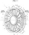
- Fig. 1 is a perspective view of a reversible fan 1 according to the embodiment of the present disclosure as viewed from the front.
- the side where wind is discharged when a motor provided to the reversible fan 1 rotates in a counterclockwise direction is referred to as the front side of the reversible fan 1.
- the side where wind is discharged when the motor rotates in a clockwise direction is referred to as the back side of the reversible fan 1.
- the left side is the front side
- the right side is the back side.
- the direction pointing to the front side along a direction of a rotation axis X (a direction of an arrow N) is referred to as the "normal direction,” and the direction pointing to the back side along the rotation direction X (a direction of an arrow R) is referred to as the "reverse direction.”
- the reversible fan 1 is a fan that can blow air (produce a current of air) in both of the normal and reverse directions.
- the reversible fan 1 includes an impeller 2 that can rotate about the rotation axis X, a motor 3 that rotates the impeller 2, a base portion 4 that supports the motor 3, and a tubular frame 5 where these members are housed.
- the impeller 2, the motor 3, and the base portion 4 are provided in such a manner as to overlap along the direction of the rotation axis X.
- the impeller 2 is formed in a substantially cup shape.
- a plurality of blades 2a is radially attached to the perimeter of the impeller 2.
- the blades 2a attached to the impeller 2 are provided in such a manner as to be inclined relative to an axial direction (the same direction as the rotation axis X) of a rotating shaft portion of the reversible fan 1. With the rotation of the blades 2a, the impeller 2 produces a current of air in the normal or reverse direction.
- the motor 3 is provided in the impeller 2.
- the motor 3 is configured as, for example, an outer rotor brushless motor.
- the motor 3 includes a stator, and a rotor that is placed outward of the stator.
- the rotor portion of the motor 3 in the impeller 2 is fixed to the impeller 2.
- the motor 3 is assembled in the impeller 2 in such a manner as to be placed on the front side (the normal direction side) relative to the impeller 2.
- the base portion 4 is formed in the form of, for example, a circular cup.
- the base portion 4 is provided in such a manner as to cover the normal direction side of the motor 3.
- the base portion 4 supports the stator portion of the motor 3.
- the base portion 4 is assembled in the frame 5 in such a manner as to be placed on the front side relative to the motor 3.
- the base portion 4 is supported by a plurality of spokes 6.
- the spokes 6 are provided in such a manner as to extend from an inner peripheral surface of the frame 5 toward the rotation axis X, and are connected to a peripheral portion of the base portion 4.
- the spokes 6 extend radially in the radial direction from the peripheral portion of the base portion 4, and are connected to the inner peripheral surface of the frame 5.
- the base portion 4 supported by the spokes 6 is attached at a position close to the front side of the tubular frame 5 extending along the rotation axis X (to the front side of the reversible fan 1).
- the spokes 6 that support the base portion 4 have a flat cross-sectional shape.
- the cross-sectional shape extends in a direction substantially along the rotation axis X, that is, a direction in which a current of air produced flows.
- the spoke 6 is formed in such a manner as to have a small surface area as viewed in the direction of the rotation axis X.
- the spoke 6 is provided with a holding portion 10 and a retaining portion 20 for holding a lead wire (illustration omitted) that supplies power to the motor 3.
- the holding portion 10 and the retaining portion 20 are provided to a predetermined spoke 6 at a position where the lead wire is placed. In the example, two spokes 6 are each provided with the holding portion 10 and the retaining portion 20.
- the frame 5 includes a main body portion 51 forming the tubular part, and a flange portion 52 (52a and 52b) provided on an outer region of each end of the main body portion 51.
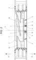
- Fig. 2 is a cross-sectional view taken along line A-A in Fig. 1 .
- Fig. 3 is a partial enlarged view illustrating the spokes 6 provided with the holding portions 10 and the retaining portions 20.
- the holding portion 10 is provided in such a manner as to jut in a direction intersecting the rotation axis X from a distal end in the normal direction (the direction of the arrow N) of the spoke 6 that is flat in such a manner as to extend along the direction of the rotation axis X. Moreover, the holding portion 10 extends in the reverse direction (the direction of the arrow R). Furthermore, the holding portion 10 has a shape that is convex toward the normal direction.
- the holding portion 10 is provided with a housing space 11 for housing a lead wire L for supply of power, the lead wire L being placed along the spoke 6.
- the holding portion 10 and a side surface of the flat spoke 6 define the housing space 11.
- the housing space 11 is formed in the form of a groove that opens in the reverse direction.
- the housing space 11 is formed in the form of a groove that extends along the length direction of the spoke 6, that is, in the form of a groove that has a length in the placement direction of the lead wire L to be placed along the spoke 6.
- the width (the length in the extension direction of the spoke 6) of the holding portion 10 is equal to or greater than 1/10 and less than 1/3 the length of the spoke 6 in the radial direction of the reversible fan 1.
- the holding portion 10 is provided in such a manner that the part forming the convex shape faces the normal direction side, that is, the opening of the housing space 11 faces the reverse direction side.
- Fig. 4 is a partial enlarged view illustrating the retaining portion 20 provided to the spoke 6.
- the retaining portion 20 is provided in such a manner as to jut in the direction intersecting the rotation axis X from an end in the reverse direction (the direction of the arrow R) of the spoke 6 that is flat in such a manner as to extend along the direction of the rotation axis X.
- the retaining portion 20 is a member for restraining the lead wire L housed in the housing space 11 from coming out of the opening of the housing space 11.
- the retaining portion 20 is provided in such a manner as to be able to surround the lead wire L in cooperation with the holding portion 10.
- Fig. 5 is a diagram illustrating the flow of wind blowing in the reverse direction in the reversible fan 1.
- Fig. 6 is a diagram illustrating the flow of wind blowing in the normal direction in the reversible fan 1.
- Fig. 7 is a perspective view illustrating a lead wire fixing portion 30 provided to the frame 5 of the reversible fan 1.
- the lead wire fixing portion 30 is a part for further fixing the lead wire L held by the holding portion 10 and the retaining portion 20 of the spoke 6.
- the lead wire fixing portion 30 includes a protruding portion 31 and an attachment groove 32.
- the protruding portion 31 is provided on a bottom surface 53 located at an end on the normal direction side of the main body portion 51 of the frame 5.
- the protruding portion 31 is provided in such a manner as to protrude from the bottom surface 53 toward the base portion 4 (toward the central part of the reversible fan 1).
- the attachment groove 32 is provided to the flange portion 52a of the frame 5 on the normal direction side.
- the attachment groove 32 is formed in such a manner as to extend across the flange portion 52a in the radial direction.
- the attachment groove 32 is formed in such a manner as to penetrate the flange portion 52a and open into the reverse direction side of the flange portion 52a.
- the attachment groove 32 is provided in such a manner as to stretch across the flange portion 52a from the protruding portion 31.
- the attachment groove 32 is provided in the approximately central part of the protruding portion 31 in such a manner as to extend in the radial direction. In other words, the attachment groove 32 divides the protruding portion 31 into two in the peripheral direction.
- the attachment groove 32 includes a straight portion 33 extending in the radial direction, and a bent portion 34 bent in the radial direction.
- the straight portion 33 is provided in the flange portion 52a.
- the bent portion 34 is provided in the protruding portion 31.
- the groove of the bent portion 34 is formed with a depth that reaches the bottom surface 53 provided with the protruding portion 31 and also reaches into a part of the main body portion 51 continuous to the bottom surface 53.
- the lead wire L held by the holding portion 10 and the retaining portion 20 of the spoke 6 is guided by the bent portion 34 and the straight portion 33 of the attachment groove 32 in such a manner as to be caught on the protruding portion 31. In this manner, the lead wire L is placed through the opening of the flange portion 52a.
- the embodiment is described in terms of the case where both of the holding portion 10 and the attachment groove 32 are provided to fix the lead wire L.
- the embodiment is not limited to this mode.
- only one of the holding portion 10 and the attachment groove 32 may be provided.
- the lead wire L is fixed only by the holding portion 10, or only by the attachment groove 32.
- the holding portion 10 that is configured to hold the lead wire L is provided to the spoke 6.
- the lead wire L is placed along the spoke 6 to apply power to the motor 3.
- the housing space 11 where the lead wire L is housed is provided between the holding portion 10 and the spoke 6.
- the housing space 11 has a groove shape that opens in the reverse direction, and extends along the spoke 6.
- the holding portion 10 is formed in such a manner as to protrude in the direction intersecting the rotation axis X from the end on the normal direction side of the spoke 6 of the flat shape extending in the direction along the rotation axis X, and to extend further in the reverse direction.
- the holding portion 10 has the convex shape facing in the normal direction.
- the current of air that hits the holding portion 10 at times of blowing in the reverse direction can flow smoothly along the convex shape.
- the holding portion 10 does not enhance the noise characteristics. As a result, it is easy to match the noise characteristics upon blowing in the normal direction with the noise characteristics upon blowing in the reverse direction.
- the holding portion 10 is formed in such a manner that the length along the spoke 6 is equal to or greater than 1/10 and less than 1/3 the radial dimension of the spoke 6. Hence, the lead wire L can be reliably held. In addition, the noise characteristics upon blowing in the normal direction can be brought close to the noise characteristics upon blowing in the reverse direction.
- the spoke 6 is provided with the retaining portion 20 configured to restrain the lead wire L housed in the housing space 11 from coming out of the opening.
- the retaining portion 20 protrudes in the direction intersecting the rotation axis X from the end of the spoke 6 in the reverse direction.
- the retaining portion 20, together with the holding portion 10 can surround the lead wire L.
- the bottom surface 53, which is located at the end of the main body portion 51 on the normal direction side, of the frame 5 is provided with the protruding portion 31 protruding toward the base portion 4.
- the attachment groove 32 configured to fix the lead wire L is provided.
- the attachment groove 32 extends in the radial direction in such a manner as to stretch across the flange portion 52a from the protruding portion 31.
- the attachment groove 32 is formed in the flange portion 52a in such a manner as to open in the reverse direction.
- the attachment groove 32 includes the bent portion 34 bent in the radial direction, in the protruding portion 31.
- the size of the flange portion 52a can be changed while the shapes of the bent portion 34 and the protruding portion 31 are maintained.
- the frame 5 of a different size can be easily designed.
- the application of the reversible fan can easily cover and extend the range of sizes.
Landscapes
- Engineering & Computer Science (AREA)
- Mechanical Engineering (AREA)
- General Engineering & Computer Science (AREA)
- Physics & Mathematics (AREA)
- Fluid Mechanics (AREA)
- Geometry (AREA)
- Power Engineering (AREA)
- Structures Of Non-Positive Displacement Pumps (AREA)
Claims (6)
- Umkehrlüfter (1), das einen Luftstrom sowohl in einer normalen Richtung (N) als auch in einer umgekehrten Richtung (R) erzeugt, wobei der Umkehrlüfter eine Vorderseite und eine Rückseite aufweist:ein einzelnes Laufrad (2), das so konfiguriert ist, dass es um eine Drehachse (X) drehbar ist, wobei eine Vielzahl von Blättern (2a) radial am Umfang des Laufrads angebracht ist;einen Motor (3), der so konfiguriert ist, dass er das Laufrad dreht, wobei die Vorderseite des Lüfters die Seite des Lüfters ist, auf der Wind ausgestoßen wird, wenn der Motor gegen den Uhrzeigersinn dreht, wobei eine Richtung, die entlang einer Richtung einer Drehachse (X) auf die Vorderseite zeigt, die normale Richtung (N) ist, die Rückseite des Lüfters die Seite des Lüfters ist, an der der Wind ausgestoßen wird, wenn der Motor im Uhrzeigersinn dreht, wobei eine Richtung, die entlang der Richtung einer Drehachse (X) zur Rückseite zeigt, die umgekehrte Richtung (R) ist, und der Motor so in das Laufrad eingebaut ist, dass er auf der Seite mit der normalen Richtung relativ zum Laufrad angeordnet ist;einen Basisabschnitt (4), der den Motor trägt und so beschaffen ist, dass er die normal ausgerichtete Seite des Motors abdeckt;einen rohrförmigen Rahmen (5), der das Laufrad, den Motor und den Basisabschnitt aufnimmt;eine Speiche (6), die sich von einer inneren Umfangsfläche des Rahmens in Richtung der Drehachse erstreckt, wobei die Speiche den Basisabschnitt trägt und eine flache Querschnittsform aufweist, die sich in einer Richtung im Wesentlichen entlang der Drehachse (X) erstreckt; undeinen Halteabschnitt (10), der so gestaltet ist, dass er mindestens einen Teil eines Leitungsdrahtes hält, um den Motor mit Strom zu versorgen, und der entlang der Speiche vorgesehen ist,wobei der Halteabschnitt so geformt ist, dass er in der Richtung, welche die Rotationsachse (X) schneidet, von einem Ende auf der Seite der normalen Richtung der Speiche, die sich in Richtung entlang der Rotationsachse erstreckt, vorsteht, und sich weiter in der umgekehrten Richtung erstreckt, so dass der Halteabschnitt eine konvexe Form hat, die in die Seite der normalen Richtung weist, und so, dass der Halteabschnitt und eine Seitenfläche der Speiche einen Gehäuseraum (11) definieren, der eine Öffnung in der Seite der umgekehrten Richtung hat und sich entlang der Speiche erstreckt.
- Umkehrlüfter nach Anspruch 1, wobei die Speiche ferner mit einem Rückhalteabschnitt (20) versehen ist, der so konfiguriert ist, dass er den in dem Gehäuseraum (11) untergebrachten Leitungsdraht daran hindert, aus der Öffnung herauszukommen.
- Umkehrlüfter nach Anspruch 2, bei dem der Rückhalteabschnitt (20) in einer die Rotationsachse (X) schneidenden Richtung von einem Ende der Speiche in die umgekehrte Richtung (R) ragt.
- Umkehrlüfter nach Anspruch 1, wobei der Halteabschnitt (10) eine Länge aufweist, die gleich oder größer als 1/10 und kleiner als 1/3 der radialen Abmessung der Speiche (6) ist.
- Umkehrlüfter nach Anspruch 1, wobeider Rahmen (5) einen Hauptkörperabschnitt (51), der ein rohrförmiges Teil bildet, und einen Flanschabschnitt (52, 52a, 52b) umfasst, der an einem äußeren Bereich des Hauptkörperabschnitts vorgesehen ist,eine Bodenfläche (53), die sich an einem Ende des Hauptkörperabschnitts in der normalen Richtung (N) befindet, mit einem vorstehenden Abschnitt (31) versehen ist, der in Richtung des Basisabschnitts (4) vorsteht,eine Befestigungsnut (32) an dem Flanschabschnitt (52a) des Rahmens auf der Seite in normaler Richtung vorgesehen ist, wobei die Befestigungsnut (32) so konfiguriert ist, dass sie den Leitungsdraht befestigt, sich in einer radialen Richtung erstreckt, sich in der Seite in umgekehrter Richtung des Flanschabschnitts öffnet und an einer Position vorgesehen ist, die sich von dem vorstehenden Abschnitt über den Flanschabschnitt erstreckt.
- Umkehrlüfter nach Anspruch 5, wobeidie Befestigungsnut (32) einen geraden Abschnitt (33), der sich in der radialen Richtung erstreckt, und einen gebogenen Abschnitt (34), der in der radialen Richtung gebogen ist, aufweist, undder gebogene Abschnitt in dem vorstehenden Abschnitt (31) vorgesehen ist.
Applications Claiming Priority (1)
| Application Number | Priority Date | Filing Date | Title |
|---|---|---|---|
| JP2021081096A JP7634421B2 (ja) | 2021-05-12 | 2021-05-12 | リバーシブルファン |
Publications (2)
| Publication Number | Publication Date |
|---|---|
| EP4089285A1 EP4089285A1 (de) | 2022-11-16 |
| EP4089285B1 true EP4089285B1 (de) | 2024-08-21 |
Family
ID=81386776
Family Applications (1)
| Application Number | Title | Priority Date | Filing Date |
|---|---|---|---|
| EP22169808.7A Active EP4089285B1 (de) | 2021-05-12 | 2022-04-25 | Umkehrlüfter |
Country Status (5)
| Country | Link |
|---|---|
| US (1) | US11572883B2 (de) |
| EP (1) | EP4089285B1 (de) |
| JP (1) | JP7634421B2 (de) |
| CN (1) | CN115342066A (de) |
| PH (1) | PH12022050189A1 (de) |
Families Citing this family (2)
| Publication number | Priority date | Publication date | Assignee | Title |
|---|---|---|---|---|
| EP3982518A1 (de) * | 2020-10-06 | 2022-04-13 | mdGroup Germany GmbH | Impeller und verfahren zum montieren eines impellers |
| JP7633878B2 (ja) * | 2021-05-12 | 2025-02-20 | 山洋電気株式会社 | リバーシブルファン |
Family Cites Families (15)
| Publication number | Priority date | Publication date | Assignee | Title |
|---|---|---|---|---|
| JPS6356024A (ja) | 1986-08-27 | 1988-03-10 | Nec Corp | 同期バ−スト送信位相制御方式 |
| TW502821U (en) * | 1999-10-20 | 2002-09-11 | Delta Electronics Inc | Wire arranging structure for fan |
| JP4442029B2 (ja) * | 2000-12-15 | 2010-03-31 | パナソニック株式会社 | 送風装置 |
| JP2003009470A (ja) | 2001-06-21 | 2003-01-10 | Toshiba Corp | ファンモータ |
| CN2630545Y (zh) * | 2003-05-30 | 2004-08-04 | 幸孺企业有限公司 | 风扇兼具灯光的结构 |
| JP2005127319A (ja) * | 2003-10-02 | 2005-05-19 | Nippon Densan Corp | ファン装置 |
| JP4469736B2 (ja) | 2005-02-07 | 2010-05-26 | 山洋電気株式会社 | 軸流送風機 |
| ATE449912T1 (de) * | 2005-08-19 | 2009-12-15 | Ebm Papst St Georgen Gmbh & Co | Lüfter |
| JP2008115696A (ja) * | 2006-10-31 | 2008-05-22 | Nippon Densan Corp | ファン装置 |
| JP5129667B2 (ja) * | 2008-06-26 | 2013-01-30 | 山洋電気株式会社 | 軸流送風機 |
| JP5832052B1 (ja) | 2015-04-24 | 2015-12-16 | 山洋電気株式会社 | 双方向軸流ファン装置 |
| JP6802022B2 (ja) | 2016-09-29 | 2020-12-16 | 山洋電気株式会社 | リバーシブルファン |
| CN207961001U (zh) * | 2018-01-17 | 2018-10-12 | 博罗县鑫正恒电子有限公司 | 一种散热风扇 |
| JP3218705U (ja) | 2018-08-23 | 2018-11-01 | 株式会社ドウシシャ | 照明器具 |
| CN211174698U (zh) | 2019-11-06 | 2020-08-04 | 深圳市东维丰电子科技股份有限公司 | 双叶片降噪正反转风扇 |
-
2021
- 2021-05-12 JP JP2021081096A patent/JP7634421B2/ja active Active
-
2022
- 2022-04-22 CN CN202210427091.1A patent/CN115342066A/zh active Pending
- 2022-04-25 EP EP22169808.7A patent/EP4089285B1/de active Active
- 2022-05-02 US US17/734,173 patent/US11572883B2/en active Active
- 2022-05-06 PH PH1/2022/050189A patent/PH12022050189A1/en unknown
Also Published As
| Publication number | Publication date |
|---|---|
| US20220364567A1 (en) | 2022-11-17 |
| US11572883B2 (en) | 2023-02-07 |
| CN115342066A (zh) | 2022-11-15 |
| JP7634421B2 (ja) | 2025-02-21 |
| PH12022050189A1 (en) | 2024-02-12 |
| JP2022175000A (ja) | 2022-11-25 |
| EP4089285A1 (de) | 2022-11-16 |
| TW202244399A (zh) | 2022-11-16 |
Similar Documents
| Publication | Publication Date | Title |
|---|---|---|
| EP4089285B1 (de) | Umkehrlüfter | |
| JP5636788B2 (ja) | 送風ファン | |
| JP5072506B2 (ja) | ファンモータ | |
| EP2069621B1 (de) | Axiallüfter | |
| EP1906028A1 (de) | Axiallüfter | |
| KR950008058B1 (ko) | 팬과 쉬라우드 조립체 | |
| CN106089758B (zh) | 双向轴流风机装置 | |
| JPH06336927A (ja) | 送風装置 | |
| JPWO2012101823A1 (ja) | サーキュレータ | |
| JP2012197740A (ja) | 軸流送風機 | |
| US20180149158A1 (en) | Centrifugal blower | |
| JP6060370B2 (ja) | 送風装置 | |
| JP5905052B2 (ja) | 遠心式ファン | |
| JP2005171987A (ja) | 小型斜流ファンモータ | |
| TWI920294B (zh) | 可逆扇 | |
| JP5353513B2 (ja) | 天井扇 | |
| US20070009353A1 (en) | Airflow generating structure and the apparatus thereof | |
| JP2006214420A5 (de) | ||
| US12203487B2 (en) | Axial fan | |
| US12055150B2 (en) | Reversible fan | |
| KR101658131B1 (ko) | 팬 슈라우드 구조 | |
| JPH0822140B2 (ja) | 電気的に操作される機械のファン | |
| JPS63285298A (ja) | 電動送風機 | |
| KR20070027807A (ko) | 모터일체형 팬쉬라우드 구조 | |
| KR20240136625A (ko) | 저소음형 터보팬 |
Legal Events
| Date | Code | Title | Description |
|---|---|---|---|
| PUAI | Public reference made under article 153(3) epc to a published international application that has entered the european phase |
Free format text: ORIGINAL CODE: 0009012 |
|
| STAA | Information on the status of an ep patent application or granted ep patent |
Free format text: STATUS: THE APPLICATION HAS BEEN PUBLISHED |
|
| AK | Designated contracting states |
Kind code of ref document: A1 Designated state(s): AL AT BE BG CH CY CZ DE DK EE ES FI FR GB GR HR HU IE IS IT LI LT LU LV MC MK MT NL NO PL PT RO RS SE SI SK SM TR |
|
| STAA | Information on the status of an ep patent application or granted ep patent |
Free format text: STATUS: REQUEST FOR EXAMINATION WAS MADE |
|
| 17P | Request for examination filed |
Effective date: 20230202 |
|
| RBV | Designated contracting states (corrected) |
Designated state(s): AL AT BE BG CH CY CZ DE DK EE ES FI FR GB GR HR HU IE IS IT LI LT LU LV MC MK MT NL NO PL PT RO RS SE SI SK SM TR |
|
| GRAP | Despatch of communication of intention to grant a patent |
Free format text: ORIGINAL CODE: EPIDOSNIGR1 |
|
| STAA | Information on the status of an ep patent application or granted ep patent |
Free format text: STATUS: GRANT OF PATENT IS INTENDED |
|
| INTG | Intention to grant announced |
Effective date: 20240430 |
|
| GRAS | Grant fee paid |
Free format text: ORIGINAL CODE: EPIDOSNIGR3 |
|
| GRAA | (expected) grant |
Free format text: ORIGINAL CODE: 0009210 |
|
| STAA | Information on the status of an ep patent application or granted ep patent |
Free format text: STATUS: THE PATENT HAS BEEN GRANTED |
|
| AK | Designated contracting states |
Kind code of ref document: B1 Designated state(s): AL AT BE BG CH CY CZ DE DK EE ES FI FR GB GR HR HU IE IS IT LI LT LU LV MC MK MT NL NO PL PT RO RS SE SI SK SM TR |
|
| REG | Reference to a national code |
Ref country code: GB Ref legal event code: FG4D |
|
| REG | Reference to a national code |
Ref country code: CH Ref legal event code: EP |
|
| REG | Reference to a national code |
Ref country code: IE Ref legal event code: FG4D |
|
| REG | Reference to a national code |
Ref country code: DE Ref legal event code: R096 Ref document number: 602022005420 Country of ref document: DE |
|
| REG | Reference to a national code |
Ref country code: LT Ref legal event code: MG9D |
|
| REG | Reference to a national code |
Ref country code: NL Ref legal event code: MP Effective date: 20240821 |
|
| PG25 | Lapsed in a contracting state [announced via postgrant information from national office to epo] |
Ref country code: NO Free format text: LAPSE BECAUSE OF FAILURE TO SUBMIT A TRANSLATION OF THE DESCRIPTION OR TO PAY THE FEE WITHIN THE PRESCRIBED TIME-LIMIT Effective date: 20241121 |
|
| REG | Reference to a national code |
Ref country code: AT Ref legal event code: MK05 Ref document number: 1715713 Country of ref document: AT Kind code of ref document: T Effective date: 20240821 |
|
| PG25 | Lapsed in a contracting state [announced via postgrant information from national office to epo] |
Ref country code: PT Free format text: LAPSE BECAUSE OF FAILURE TO SUBMIT A TRANSLATION OF THE DESCRIPTION OR TO PAY THE FEE WITHIN THE PRESCRIBED TIME-LIMIT Effective date: 20241223 Ref country code: GR Free format text: LAPSE BECAUSE OF FAILURE TO SUBMIT A TRANSLATION OF THE DESCRIPTION OR TO PAY THE FEE WITHIN THE PRESCRIBED TIME-LIMIT Effective date: 20241122 Ref country code: NL Free format text: LAPSE BECAUSE OF FAILURE TO SUBMIT A TRANSLATION OF THE DESCRIPTION OR TO PAY THE FEE WITHIN THE PRESCRIBED TIME-LIMIT Effective date: 20240821 Ref country code: FI Free format text: LAPSE BECAUSE OF FAILURE TO SUBMIT A TRANSLATION OF THE DESCRIPTION OR TO PAY THE FEE WITHIN THE PRESCRIBED TIME-LIMIT Effective date: 20240821 Ref country code: PL Free format text: LAPSE BECAUSE OF FAILURE TO SUBMIT A TRANSLATION OF THE DESCRIPTION OR TO PAY THE FEE WITHIN THE PRESCRIBED TIME-LIMIT Effective date: 20240821 |
|
| PG25 | Lapsed in a contracting state [announced via postgrant information from national office to epo] |
Ref country code: BG Free format text: LAPSE BECAUSE OF FAILURE TO SUBMIT A TRANSLATION OF THE DESCRIPTION OR TO PAY THE FEE WITHIN THE PRESCRIBED TIME-LIMIT Effective date: 20240821 |
|
| PG25 | Lapsed in a contracting state [announced via postgrant information from national office to epo] |
Ref country code: LV Free format text: LAPSE BECAUSE OF FAILURE TO SUBMIT A TRANSLATION OF THE DESCRIPTION OR TO PAY THE FEE WITHIN THE PRESCRIBED TIME-LIMIT Effective date: 20240821 |
|
| PG25 | Lapsed in a contracting state [announced via postgrant information from national office to epo] |
Ref country code: AT Free format text: LAPSE BECAUSE OF FAILURE TO SUBMIT A TRANSLATION OF THE DESCRIPTION OR TO PAY THE FEE WITHIN THE PRESCRIBED TIME-LIMIT Effective date: 20240821 Ref country code: IS Free format text: LAPSE BECAUSE OF FAILURE TO SUBMIT A TRANSLATION OF THE DESCRIPTION OR TO PAY THE FEE WITHIN THE PRESCRIBED TIME-LIMIT Effective date: 20241221 |
|
| PG25 | Lapsed in a contracting state [announced via postgrant information from national office to epo] |
Ref country code: HR Free format text: LAPSE BECAUSE OF FAILURE TO SUBMIT A TRANSLATION OF THE DESCRIPTION OR TO PAY THE FEE WITHIN THE PRESCRIBED TIME-LIMIT Effective date: 20240821 |
|
| PG25 | Lapsed in a contracting state [announced via postgrant information from national office to epo] |
Ref country code: RS Free format text: LAPSE BECAUSE OF FAILURE TO SUBMIT A TRANSLATION OF THE DESCRIPTION OR TO PAY THE FEE WITHIN THE PRESCRIBED TIME-LIMIT Effective date: 20241121 Ref country code: ES Free format text: LAPSE BECAUSE OF FAILURE TO SUBMIT A TRANSLATION OF THE DESCRIPTION OR TO PAY THE FEE WITHIN THE PRESCRIBED TIME-LIMIT Effective date: 20240821 |
|
| PG25 | Lapsed in a contracting state [announced via postgrant information from national office to epo] |
Ref country code: RS Free format text: LAPSE BECAUSE OF FAILURE TO SUBMIT A TRANSLATION OF THE DESCRIPTION OR TO PAY THE FEE WITHIN THE PRESCRIBED TIME-LIMIT Effective date: 20241121 Ref country code: PT Free format text: LAPSE BECAUSE OF FAILURE TO SUBMIT A TRANSLATION OF THE DESCRIPTION OR TO PAY THE FEE WITHIN THE PRESCRIBED TIME-LIMIT Effective date: 20241223 Ref country code: PL Free format text: LAPSE BECAUSE OF FAILURE TO SUBMIT A TRANSLATION OF THE DESCRIPTION OR TO PAY THE FEE WITHIN THE PRESCRIBED TIME-LIMIT Effective date: 20240821 Ref country code: NO Free format text: LAPSE BECAUSE OF FAILURE TO SUBMIT A TRANSLATION OF THE DESCRIPTION OR TO PAY THE FEE WITHIN THE PRESCRIBED TIME-LIMIT Effective date: 20241121 Ref country code: NL Free format text: LAPSE BECAUSE OF FAILURE TO SUBMIT A TRANSLATION OF THE DESCRIPTION OR TO PAY THE FEE WITHIN THE PRESCRIBED TIME-LIMIT Effective date: 20240821 Ref country code: LV Free format text: LAPSE BECAUSE OF FAILURE TO SUBMIT A TRANSLATION OF THE DESCRIPTION OR TO PAY THE FEE WITHIN THE PRESCRIBED TIME-LIMIT Effective date: 20240821 Ref country code: IS Free format text: LAPSE BECAUSE OF FAILURE TO SUBMIT A TRANSLATION OF THE DESCRIPTION OR TO PAY THE FEE WITHIN THE PRESCRIBED TIME-LIMIT Effective date: 20241221 Ref country code: HR Free format text: LAPSE BECAUSE OF FAILURE TO SUBMIT A TRANSLATION OF THE DESCRIPTION OR TO PAY THE FEE WITHIN THE PRESCRIBED TIME-LIMIT Effective date: 20240821 Ref country code: GR Free format text: LAPSE BECAUSE OF FAILURE TO SUBMIT A TRANSLATION OF THE DESCRIPTION OR TO PAY THE FEE WITHIN THE PRESCRIBED TIME-LIMIT Effective date: 20241122 Ref country code: FI Free format text: LAPSE BECAUSE OF FAILURE TO SUBMIT A TRANSLATION OF THE DESCRIPTION OR TO PAY THE FEE WITHIN THE PRESCRIBED TIME-LIMIT Effective date: 20240821 Ref country code: ES Free format text: LAPSE BECAUSE OF FAILURE TO SUBMIT A TRANSLATION OF THE DESCRIPTION OR TO PAY THE FEE WITHIN THE PRESCRIBED TIME-LIMIT Effective date: 20240821 Ref country code: BG Free format text: LAPSE BECAUSE OF FAILURE TO SUBMIT A TRANSLATION OF THE DESCRIPTION OR TO PAY THE FEE WITHIN THE PRESCRIBED TIME-LIMIT Effective date: 20240821 Ref country code: AT Free format text: LAPSE BECAUSE OF FAILURE TO SUBMIT A TRANSLATION OF THE DESCRIPTION OR TO PAY THE FEE WITHIN THE PRESCRIBED TIME-LIMIT Effective date: 20240821 |
|
| PG25 | Lapsed in a contracting state [announced via postgrant information from national office to epo] |
Ref country code: DK Free format text: LAPSE BECAUSE OF FAILURE TO SUBMIT A TRANSLATION OF THE DESCRIPTION OR TO PAY THE FEE WITHIN THE PRESCRIBED TIME-LIMIT Effective date: 20240821 Ref country code: SM Free format text: LAPSE BECAUSE OF FAILURE TO SUBMIT A TRANSLATION OF THE DESCRIPTION OR TO PAY THE FEE WITHIN THE PRESCRIBED TIME-LIMIT Effective date: 20240821 Ref country code: RO Free format text: LAPSE BECAUSE OF FAILURE TO SUBMIT A TRANSLATION OF THE DESCRIPTION OR TO PAY THE FEE WITHIN THE PRESCRIBED TIME-LIMIT Effective date: 20240821 |
|
| PG25 | Lapsed in a contracting state [announced via postgrant information from national office to epo] |
Ref country code: EE Free format text: LAPSE BECAUSE OF FAILURE TO SUBMIT A TRANSLATION OF THE DESCRIPTION OR TO PAY THE FEE WITHIN THE PRESCRIBED TIME-LIMIT Effective date: 20240821 |
|
| PG25 | Lapsed in a contracting state [announced via postgrant information from national office to epo] |
Ref country code: CZ Free format text: LAPSE BECAUSE OF FAILURE TO SUBMIT A TRANSLATION OF THE DESCRIPTION OR TO PAY THE FEE WITHIN THE PRESCRIBED TIME-LIMIT Effective date: 20240821 |
|
| PG25 | Lapsed in a contracting state [announced via postgrant information from national office to epo] |
Ref country code: SK Free format text: LAPSE BECAUSE OF FAILURE TO SUBMIT A TRANSLATION OF THE DESCRIPTION OR TO PAY THE FEE WITHIN THE PRESCRIBED TIME-LIMIT Effective date: 20240821 Ref country code: IT Free format text: LAPSE BECAUSE OF FAILURE TO SUBMIT A TRANSLATION OF THE DESCRIPTION OR TO PAY THE FEE WITHIN THE PRESCRIBED TIME-LIMIT Effective date: 20240821 |
|
| REG | Reference to a national code |
Ref country code: DE Ref legal event code: R097 Ref document number: 602022005420 Country of ref document: DE |
|
| PLBE | No opposition filed within time limit |
Free format text: ORIGINAL CODE: 0009261 |
|
| STAA | Information on the status of an ep patent application or granted ep patent |
Free format text: STATUS: NO OPPOSITION FILED WITHIN TIME LIMIT |
|
| PGFP | Annual fee paid to national office [announced via postgrant information from national office to epo] |
Ref country code: DE Payment date: 20250422 Year of fee payment: 4 |
|
| 26N | No opposition filed |
Effective date: 20250522 |
|
| PG25 | Lapsed in a contracting state [announced via postgrant information from national office to epo] |
Ref country code: SE Free format text: LAPSE BECAUSE OF FAILURE TO SUBMIT A TRANSLATION OF THE DESCRIPTION OR TO PAY THE FEE WITHIN THE PRESCRIBED TIME-LIMIT Effective date: 20240821 |
|
| REG | Reference to a national code |
Ref country code: CH Ref legal event code: H13 Free format text: ST27 STATUS EVENT CODE: U-0-0-H10-H13 (AS PROVIDED BY THE NATIONAL OFFICE) Effective date: 20251125 |
|
| PG25 | Lapsed in a contracting state [announced via postgrant information from national office to epo] |
Ref country code: LU Free format text: LAPSE BECAUSE OF NON-PAYMENT OF DUE FEES Effective date: 20250425 |
|
| PG25 | Lapsed in a contracting state [announced via postgrant information from national office to epo] |
Ref country code: MC Free format text: LAPSE BECAUSE OF FAILURE TO SUBMIT A TRANSLATION OF THE DESCRIPTION OR TO PAY THE FEE WITHIN THE PRESCRIBED TIME-LIMIT Effective date: 20240821 |
|
| REG | Reference to a national code |
Ref country code: BE Ref legal event code: MM Effective date: 20250430 |
|
| PG25 | Lapsed in a contracting state [announced via postgrant information from national office to epo] |
Ref country code: FR Free format text: LAPSE BECAUSE OF NON-PAYMENT OF DUE FEES Effective date: 20250430 |
|
| PG25 | Lapsed in a contracting state [announced via postgrant information from national office to epo] |
Ref country code: BE Free format text: LAPSE BECAUSE OF NON-PAYMENT OF DUE FEES Effective date: 20250430 |
|
| PG25 | Lapsed in a contracting state [announced via postgrant information from national office to epo] |
Ref country code: CH Free format text: LAPSE BECAUSE OF NON-PAYMENT OF DUE FEES Effective date: 20250430 |
|
| PG25 | Lapsed in a contracting state [announced via postgrant information from national office to epo] |
Ref country code: IE Free format text: LAPSE BECAUSE OF NON-PAYMENT OF DUE FEES Effective date: 20250425 |