EP4084234B1 - Electronic equipment - Google Patents
Electronic equipment Download PDFInfo
- Publication number
- EP4084234B1 EP4084234B1 EP22163795.2A EP22163795A EP4084234B1 EP 4084234 B1 EP4084234 B1 EP 4084234B1 EP 22163795 A EP22163795 A EP 22163795A EP 4084234 B1 EP4084234 B1 EP 4084234B1
- Authority
- EP
- European Patent Office
- Prior art keywords
- protrusion
- waterproofing member
- contact
- connector
- contact portion
- Prior art date
- Legal status (The legal status is an assumption and is not a legal conclusion. Google has not performed a legal analysis and makes no representation as to the accuracy of the status listed.)
- Active
Links
Images


Classifications
-
- H—ELECTRICITY
- H01—ELECTRIC ELEMENTS
- H01R—ELECTRICALLY-CONDUCTIVE CONNECTIONS; STRUCTURAL ASSOCIATIONS OF A PLURALITY OF MUTUALLY-INSULATED ELECTRICAL CONNECTING ELEMENTS; COUPLING DEVICES; CURRENT COLLECTORS
- H01R13/00—Details of coupling devices of the kinds covered by groups H01R12/70 or H01R24/00 - H01R33/00
- H01R13/46—Bases; Cases
- H01R13/52—Dustproof, splashproof, drip-proof, waterproof, or flameproof cases
- H01R13/5219—Sealing means between coupling parts, e.g. interfacial seal
-
- H—ELECTRICITY
- H01—ELECTRIC ELEMENTS
- H01R—ELECTRICALLY-CONDUCTIVE CONNECTIONS; STRUCTURAL ASSOCIATIONS OF A PLURALITY OF MUTUALLY-INSULATED ELECTRICAL CONNECTING ELEMENTS; COUPLING DEVICES; CURRENT COLLECTORS
- H01R13/00—Details of coupling devices of the kinds covered by groups H01R12/70 or H01R24/00 - H01R33/00
- H01R13/46—Bases; Cases
- H01R13/52—Dustproof, splashproof, drip-proof, waterproof, or flameproof cases
- H01R13/5202—Sealing means between parts of housing or between housing part and a wall, e.g. sealing rings
-
- H—ELECTRICITY
- H01—ELECTRIC ELEMENTS
- H01R—ELECTRICALLY-CONDUCTIVE CONNECTIONS; STRUCTURAL ASSOCIATIONS OF A PLURALITY OF MUTUALLY-INSULATED ELECTRICAL CONNECTING ELEMENTS; COUPLING DEVICES; CURRENT COLLECTORS
- H01R13/00—Details of coupling devices of the kinds covered by groups H01R12/70 or H01R24/00 - H01R33/00
- H01R13/46—Bases; Cases
- H01R13/52—Dustproof, splashproof, drip-proof, waterproof, or flameproof cases
- H01R13/5216—Dustproof, splashproof, drip-proof, waterproof, or flameproof cases characterised by the sealing material, e.g. gels or resins
-
- H—ELECTRICITY
- H01—ELECTRIC ELEMENTS
- H01R—ELECTRICALLY-CONDUCTIVE CONNECTIONS; STRUCTURAL ASSOCIATIONS OF A PLURALITY OF MUTUALLY-INSULATED ELECTRICAL CONNECTING ELEMENTS; COUPLING DEVICES; CURRENT COLLECTORS
- H01R13/00—Details of coupling devices of the kinds covered by groups H01R12/70 or H01R24/00 - H01R33/00
- H01R13/73—Means for mounting coupling parts to apparatus or structures, e.g. to a wall
- H01R13/74—Means for mounting coupling parts in openings of a panel
-
- H—ELECTRICITY
- H05—ELECTRIC TECHNIQUES NOT OTHERWISE PROVIDED FOR
- H05K—PRINTED CIRCUITS; CASINGS OR CONSTRUCTIONAL DETAILS OF ELECTRIC APPARATUS; MANUFACTURE OF ASSEMBLAGES OF ELECTRICAL COMPONENTS
- H05K5/00—Casings, cabinets or drawers for electric apparatus
-
- H—ELECTRICITY
- H01—ELECTRIC ELEMENTS
- H01R—ELECTRICALLY-CONDUCTIVE CONNECTIONS; STRUCTURAL ASSOCIATIONS OF A PLURALITY OF MUTUALLY-INSULATED ELECTRICAL CONNECTING ELEMENTS; COUPLING DEVICES; CURRENT COLLECTORS
- H01R12/00—Structural associations of a plurality of mutually-insulated electrical connecting elements, specially adapted for printed circuits, e.g. printed circuit boards [PCB], flat or ribbon cables, or like generally planar structures, e.g. terminal strips, terminal blocks; Coupling devices specially adapted for printed circuits, flat or ribbon cables, or like generally planar structures; Terminals specially adapted for contact with, or insertion into, printed circuits, flat or ribbon cables, or like generally planar structures
- H01R12/70—Coupling devices
- H01R12/71—Coupling devices for rigid printing circuits or like structures
- H01R12/712—Coupling devices for rigid printing circuits or like structures co-operating with the surface of the printed circuit or with a coupling device exclusively provided on the surface of the printed circuit
- H01R12/716—Coupling device provided on the PCB
Definitions
- This invention relates to an electronic equipment comprising a connector having a waterproofing member.
- WO 20101027009 A1 discloses: A connector formed by integrally combining a connector connecting section and a pipe connecting section is configured compact and facilitates fitting operation.
- a connector is provided with a pair of pipe connecting sections and a pair of connector connecting sections, the pairs being provided in a first connector housing and a second connector housing and being connected to each other in a main hood; a pipe seal member for sealing between the pair of the pipe connecting sections; a connector seal member for sealing between the pair of connector connecting sections; and a lever for drawing and fitting to each other the first connector housing and the second connector housing by means of a cam action occurring between a cam pin provided to either the first connector housing or the second connector housing and a cam groove provided in the other.
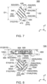
- JPA2014-112484 discloses an electronic equipment 900 of this type.
- the electronic equipment 900 comprises a housing 910 and a housing-side connection portion 920, or a connector 920.
- the connector 920 is attached to a wall surface 912 of the housing 910.
- the connector 920 is mateable along a Z-direction with a cable-side connection portion, or a mating connector, which is not shown in the figure.
- the connector 920 comprises a housing-side housing portion 922, or a housing 922, a first waterproofing rubber 924, a second waterproofing rubber 925 and a gap waterproofing rubber 926.
- the electronic equipment 900 forms a waterproof seal between the housing 922 and the wall surface 912 by using the first waterproofing rubber 924 and the second waterproofing rubber 925 of the connector 920.
- the electronic equipment 900 and the mating connector form a waterproof seal between the housing 922 of the connector 920 and a cable-side housing, which is not shown in the figure, of the mating connector by using the gap waterproofing rubber 926 when the connector 920 and the mating connector are mated with each other.
- the present invention provides an electronic equipment comprising a case and a connector which is attached to the case.
- the case has a main portion.
- the main portion has a top surface and a back surface in a first direction.
- the main portion has an opening.
- the opening pierces the main portion in the first direction.
- the connector is mateable along the first direction with a mating connector which is inserted through the opening.
- the connector comprises a housing and a waterproofing member.
- the housing has a bottom portion and a side portion. The bottom portion is positioned away from the back surface of the main portion in the first direction.
- the side portion extends from the bottom portion toward the back surface of the main portion in the first direction.
- the waterproofing member has an elastic property and is attached to the housing.
- the waterproofing member is sandwiched by the bottom portion and the back surface of the main portion in the first direction.
- the waterproofing member is sandwiched by the mating connector and the side portion in a second direction perpendicular to the first direction when the connector is mated with the mating connector.
- the waterproofing member has at least one first contact portion, at least one second contact portion, at least one third contact portion and at least one fourth contact portion.
- the first contact portion is pressed against and in contact with the bottom portion in the first direction by the elasticity of the waterproofing member.
- the second contact portion is pressed against and in contact with the back surface of the main portion in the first direction by the elasticity of the waterproofing member.
- the third contact portion is in contact with the side portion in the second direction.
- the third contact portion is pressed against the side portion in the second direction by the elasticity of the waterproofing member upon the mating of the connector with the mating connector.
- the fourth contact portion protrudes inward in the second direction beyond the opening.
- the fourth contact portion is pressed against and in contact with the mating connector in the second direction by the elasticity of the waterproofing member upon the mating of the connector with the mating connector.
- the electronic equipment of the present invention is configured as follows: the waterproofing member has the at least one first contact portion, the at least one second contact portion, the at least one third contact portion and the at least one fourth contact portion; the first contact portion is pressed against and in contact with the bottom portion of the housing of the connector in the first direction by the elasticity of the waterproofing member; the second contact portion is pressed against and in contact with the back surface of the main portion of the case in the first direction by the elasticity of the waterproofing member; the third contact portion is in contact with the side portion of the housing of the connector in the second direction; the third contact portion is pressed against the side portion of the housing of the connector in the second direction by the elasticity of the waterproofing member upon the mating of the connector with the mating connector; and the fourth contact portion is pressed against and in contact with the mating connector in the second direction by the elasticity of the waterproofing member upon the mating of the connector with the mating connector.
- the electronic equipment of the present invention is configured so that the single waterproofing member provides a waterproof seal between the connector and the case and provides a waterproof seal between the connector and the mating connector.
- the electronic equipment of the present invention comprises the connector which has a reduced number of waterproofing components.
- an assembly 870 according to a first embodiment of the present invention comprises an electronic equipment 10 and a mating connector 800.
- the mating connector 800 of the present embodiment comprises a mating housing 810 and a plurality of mating terminals 820.
- the mating housing 810 has an abutment portion 812 which faces outward in a second direction perpendicular to a first direction.
- the first direction is a Z-direction.
- the first direction is also referred to as an up-down direction. Specifically, it is assumed that upward is a positive Z-direction while downward is a negative Z-direction.
- the mating terminals 820 are held by the mating housing 810.
- the electronic equipment 10 of the present embodiment comprises a case 600 and a connector 100.
- the case 600 of the present embodiment is made of resin.
- the case 600 has a main portion 610.
- the main portion 610 of the present embodiment has a flat-plate shape perpendicular to the first direction.
- the main portion 610 has a top surface 612 and a back surface 614 in the first direction.
- the top surface 612 faces outward in the first direction. Specifically, the top surface 612 faces upward in the up-down direction.
- the back surface 614 faces inward in the first direction. Specifically, the back surface 614 faces downward in the up-down direction.
- the main portion 610 is provided with an opening 616. The opening 616 pierces the main portion 610 in the first direction.
- the connector 100 of the present embodiment is attached to the case 600.
- the connector 100 is configured to be mounted on a circuit board 850.
- the connector 100 is mateable along the first direction with the mating connector 800 which is inserted through the opening 616. More specifically, the connector 100 is mateable along the up-down direction with the mating connector 800 which is inserted through the opening 616 from above.
- the connector 100 comprises a housing 200, a plurality of terminals 500 and a waterproofing member 300.
- the housing 200 of the present embodiment is made of insulator. As shown in Fig. 5 , the housing 200 has a bottom portion 210 and a side portion 230.
- the bottom portion 210 of the present embodiment has a flat-plate shape perpendicular to the first direction.
- the bottom portion 210 is positioned around an end portion of the connector 100 in the second direction perpendicular to the first direction.
- the bottom portion 210 is positioned away from the back surface 614 of the main portion 610 in the first direction.
- the side portion 230 of the present embodiment has a substantially rectangular shape when viewed along the first direction. As shown in Fig. 5 , the side portion 230 extends from the bottom portion 210 toward the back surface 614 of the main portion 610 in the first direction. Specifically, the side portion 230 extends upward in the up-down direction from the bottom portion 210.
- the electronic equipment 10 is formed with a gap 170 between the case 600 and the side portion 230 of the housing 200. In other words, the back surface 614 of the main portion 610 and the side portion 230 of the housing 200 are spaced away from each other in the first direction.
- the side portion 230 extends upward from an outer end of the bottom portion 210 in the second direction.
- a part consisting of the bottom portion 210 and the side portion 230 has an L-shaped cross-section in a plane which includes the first direction.
- a part consisting of the case 600, and the bottom portion 210 and the side portion 230 of the housing 200 has a substantially angular C-shaped cross-section in the plane which includes the first direction. Specifically, the substantially angular C-shaped cross-section opens inward in the second direction perpendicular to the first direction.
- the part consisting of the case 600, and the bottom portion 210 and the side portion 230 of the housing 200 forms a groove-like recess which accommodates the waterproofing member 300.
- each of the terminals 500 of the present embodiment is made of metal.
- the terminals 500 are held by the housing 200.
- the terminals 500 are connected with the mating terminals 820, respectively, when the connector 100 and the mating connector 800 are mated with each other.
- the waterproofing member 300 of the present embodiment has a rectangular ring shape with rounded corners when viewed along the first direction.
- the waterproofing member 300 has an elastic property.
- the waterproofing member 300 is made of seamless rubber.
- the waterproofing member 300 is a discrete member. As shown in Fig. 5 , the waterproofing member 300 is attached to the housing 200.
- the waterproofing member 300 in a state before the waterproofing member 300 is attached to the housing 200, the waterproofing member 300 has a shape which is mirror-symmetrical with respect to a plane perpendicular to the first direction.
- the plane perpendicular to the first direction is an XY-plane.
- the XY-plane is also referred to as a horizontal plane.
- the waterproofing member 300 is sandwiched by the bottom portion 210 and the back surface 614 of the main portion 610 in the first direction. More specifically, in the first direction, the waterproofing member 300 is sandwiched by the bottom portion 210 and the back surface 614 of the main portion 610 and is brought into contact with both of the bottom portion 210 and the back surface 614 of the main portion 610. In other words, the electronic equipment 10 forms a waterproof seal between the connector 100 and the case 600 by using the waterproofing member 300.
- the waterproofing member 300 is sandwiched by the mating connector 800 and the side portion 230 in the second direction perpendicular to the first direction when the connector 100 is mated with the mating connector 800.
- the assembly 870 forms a waterproof seal between the connector 100 and the mating connector 800 by using the waterproofing member 300.
- the electronic equipment 10 of the present embodiment is configured so that the single waterproofing member 300 provides the waterproof seal between the connector 100 and the case 600 and provides the waterproof seal between the connector 100 and the mating connector 800.
- the single waterproofing member 300 is brought into contact with three members, namely the connector 100, the case 600 and the mating connector 800, when the connector 100 is mated with the mating connector 800.
- the waterproofing member 300 has two first contact portions 310, two second contact portions 320, two third contact portions 330 and a fourth contact portion 340.
- the present invention is not limited thereto.
- the waterproofing member 300 should have at least one first contact portion 310, at least one second contact portion 320, at least one third contact portion 330 and at least one fourth contact portion 340.
- the first contact portions 310 of the present embodiment are positioned away from each other in the second direction in the state before the waterproofing member 300 is attached to the housing 200. As shown in Fig. 5 , the first contact portions 310 are positioned away from each other in the second direction under a state where the waterproofing member 300 is attached to the housing 200.
- each of the first contact portions 310 is pressed against and in contact with the bottom portion 210 in the first direction by the elasticity of the waterproofing member 300.
- the first contact portions 310 of the present embodiment include a first main contact portion 312 and a first sub contact portion 314.
- the present invention is not limited thereto.
- the first contact portions 310 may not include the first sub contact portion 314.
- the first main contact portion 312 of the present embodiment defines an outer end of the waterproofing member 300 in the first direction. Specifically, the first main contact portion 312 defines a lower end of the waterproofing member 300 in the up-down direction.
- the first main contact portion 312 is positioned between the fourth contact portion 340 and any of the third contact portions 330 in the second direction.
- the first main contact portion 312 is positioned inward in the second direction beyond any of the third contact portions 330.
- the first main contact portion 312 is positioned outward in the second direction beyond the fourth contact portion 340.
- the first main contact portion 312 is positioned outward in the second direction beyond the opening 616.
- the first main contact portion 312 of the first contact portions 310 is positioned between the side portion 230 and the fourth contact portion 340 in the second direction.
- the first main contact portion 312 of the first contact portions 310 is positioned closer to the fourth contact portion 340 than to the side portion 230 in the second direction. More specifically, under the state where the waterproofing member 300 is attached to the housing 200, the first main contact portion 312 of the first contact portions 310 is positioned closer to the fourth contact portion 340 than to the side portion 230 in the second direction.
- the first sub contact portion 314 of the present embodiment is positioned outward in the second direction beyond the first main contact portion 312.
- the first sub contact portion 314 is positioned between the fourth contact portion 340 and any of the third contact portions 330 in the second direction.
- the first sub contact portion 314 is positioned inward in the second direction beyond any of the third contact portions 330.
- the first sub contact portion 314 is positioned outward in the second direction beyond the fourth contact portion 340.
- the second contact portions 320 of the present embodiment are positioned away from each other in the second direction in the state before the waterproofing member 300 is attached to the housing 200. As shown in Fig. 5 , the second contact portions 320 are positioned away from each other in the second direction under the state where the waterproofing member 300 is attached to the housing 200.
- each of the second contact portions 320 is pressed against and in contact with the back surface 614 of the main portion 610 in the first direction by the elasticity of the waterproofing member 300.
- the second contact portions 320 of the present embodiment include a second main contact portion 322 and a second sub contact portion 324.
- the present invention is not limited thereto.
- the second contact portions 320 may not include the second sub contact portion 324.
- the second main contact portion 322 of the present embodiment defines an outer end of the waterproofing member 300 in the first direction. Specifically, the second main contact portion 322 defines an upper end of the waterproofing member 300 in the up-down direction.
- the second main contact portion 322 is positioned between the fourth contact portion 340 and any of the third contact portions 330 in the second direction.
- the second main contact portion 322 is positioned inward in the second direction beyond any of the third contact portions 330.
- the second main contact portion 322 is positioned outward in the second direction beyond the fourth contact portion 340.
- the second main contact portion 322 is positioned outward in the second direction beyond the opening 616.
- the second main contact portion 322 of the second contact portions 320 is positioned between the side portion 230 and the fourth contact portion 340 in the second direction.
- the second main contact portion 322 of the second contact portions 320 is positioned closer to the fourth contact portion 340 than to the side portion 230 in the second direction. More specifically, under the state where the waterproofing member 300 is attached to the housing 200, the second main contact portion 322 of the second contact portions 320 is positioned closer to the fourth contact portion 340 than to the side portion 230 in the second direction.
- the second main contact portion 322 of the second contact portions 320 is positioned at a position same as a position of the first main contact portion 312 of the first contact portions 310 in the second direction. This enables the waterproofing member 300 to be reliably held by the connector 100 when the waterproofing member 300 is sandwiched by the case 600 and the bottom portion 210 of the housing 200.
- the second sub contact portion 324 of the present embodiment is positioned between the second main contact portion 322 and any of the third contact portions 330 in the second direction.
- the second sub contact portion 324 is positioned outward in the second direction beyond the second main contact portion 322.
- the second sub contact portion 324 is positioned inward in the second direction beyond any of the third contact portions 330.
- the second sub contact portion 324 is positioned between the fourth contact portion 340 and any of the third contact portions 330 in the second direction.
- the second sub contact portion 324 is positioned outward in the second direction beyond the fourth contact portion 340.
- each of the third contact portions 330 of the present embodiment forms a curved surface which protrudes outward in the second direction in the state before the waterproofing member 300 is attached to the housing 200.
- the third contact portions 330 are positioned away from each other in the first direction in the state before the waterproofing member 300 is attached to the housing 200.
- the third contact portions 330 are positioned away from each other in the first direction under the state where the waterproofing member 300 is attached to the housing 200.
- each of the third contact portions 330 is in contact with the side portion 230 in the second direction. As shown in Fig. 4 , each of the third contact portions 330 is pressed against the side portion 230 in the second direction by the elasticity of the waterproofing member 300 upon the mating of the connector 100 with the mating connector 800.
- the third contact portions 330 of the present embodiment include a third main contact portion 332 and a third sub contact portion 334.
- the third main contact portion 332 of the present embodiment defines an outer end of the waterproofing member 300 in the second direction.
- the third main contact portion 332 is positioned between any of the first contact portions 310 and any of the second contact portions 320 in the first direction.
- the third main contact portion 332 is positioned inward in the first direction beyond any of the first contact portions 310.
- the third main contact portion 332 is positioned inward in the first direction beyond any of the second contact portions 320.
- the third sub contact portion 334 of the present embodiment defines the outer end of the waterproofing member 300 in the second direction.
- the third sub contact portion 334 is positioned between any of the first contact portions 310 and any of the second contact portions 320 in the first direction.
- the third sub contact portion 334 is positioned inward in the first direction beyond any of the first contact portions 310.
- the third sub contact portion 334 is positioned inward in the first direction beyond any of the second contact portions 320.
- the third sub contact portion 334 is positioned above the third main contact portion 332 in the up-down direction.
- the fourth contact portion 340 of the present embodiment defines an inner end of the waterproofing member 300 in the second direction.
- the fourth contact portion 340 protrudes inward in the second direction beyond the opening 616.
- the fourth contact portion 340 is positioned at a first side of the waterproofing member 300 in the second direction.
- a circumferential length of the fourth contact portion 340 is shorter than a circumferential length of the abutment portion 812 under an unmated state where the connector 100 and the mating connector 800 are not mated with each other.
- a distance between the fourth contact portion 340 and the third main contact portion 332 in the second direction under the unmated state is greater than a distance between the side portion 230 and the abutment portion 812 in the second direction upon the mating of the connector 100 with the mating connector 800.
- a distance between the fourth contact portion 340 and the third sub contact portion 334 in the second direction under the unmated state is greater than the distance between the side portion 230 and the abutment portion 812 in the second direction upon the mating of the connector 100 with the mating connector 800.
- the fourth contact portion 340 is pressed against and in contact with the mating connector 800 in the second direction by the elasticity of the waterproofing member 300 upon the mating of the connector 100 with the mating connector 800. More specifically, the fourth contact portion 340 is pressed against and in contact with the abutment portion 812 of the mating housing 810 in the second direction by the elasticity of the waterproofing member 300 upon the mating of the connector 100 with the mating connector 800.
- one of the first contact portions 310 is positioned closer to the fourth contact portion 340 than to the side portion 230 in the second direction. Accordingly, even in a case where the fourth contact portion 340 is pushed down upon the mating of the connector 100 with the mating connector 800, the waterproofing member 300 is prevented from being rotated about an axis which is perpendicular to both the first direction and the second direction. Thus, the third contact portions 330 are prevented from being moved upward even in this case.
- the connector 100 is formed with a space 150 between the waterproofing member 300 and the side portion 230.
- the space 150 is positioned between the third contact portions 330 in the first direction. Specifically, the space 150 is positioned between the third main contact portion 332 and the third sub contact portion 334 in the first direction. Accordingly, even when the connector 100 is mated with the mating connector 800, the third sub contact portion 334 is hardly moved upward in comparison with an assumption where the waterproofing member 300 be brought into close contact with the side portion 230 without the space 150.
- the waterproofing member 300 has a first protrusion 410, a second protrusion 420, a third protrusion 430, a fourth protrusion 440 and a fifth protrusion 450.
- the first protrusion 410 of the present embodiment protrudes outward in the first direction. Specifically, the first protrusion 410 protrudes downward in the up-down direction. The first protrusion 410 is positioned at a position same as a position of the second protrusion 420 in the second direction. The first protrusion 410 is positioned between the third protrusion 430 and the fifth protrusion 450 in the second direction. The first protrusion 410 is positioned between the fourth protrusion 440 and the fifth protrusion 450 in the second direction. The first main contact portion 312 of the first contact portions 310 is provided on the first protrusion 410.
- the second protrusion 420 of the present embodiment protrudes outward in the first direction. Specifically, the second protrusion 420 protrudes upward in the up-down direction.
- the second protrusion 420 is positioned at the position same as the position of the first protrusion 410 in the second direction.
- the second protrusion 420 is positioned between the third protrusion 430 and the fifth protrusion 450 in the second direction.
- the second protrusion 420 is positioned between the fourth protrusion 440 and the fifth protrusion 450 in the second direction.
- the second main contact portion 322 of the second contact portions 320 is provided on the second protrusion 420.
- the third protrusion 430 of the present embodiment protrudes outward in the first direction and extends outward in the second direction. Specifically, the third protrusion 430 protrudes downward in the up-down direction and extends outward in the second direction. The third protrusion 430 is positioned outward in the second direction beyond the first protrusion 410. The third protrusion 430 is positioned outward in the second direction beyond the second protrusion 420. The third protrusion 430 is positioned outward in the second direction beyond the fifth protrusion 450.
- the first sub contact portion 314 of the first contact portions 310 is provided on the third protrusion 430. Additionally, the third main contact portion 332 of the third contact portions 330 is provided on the third protrusion 430.
- the waterproofing member 300 is formed with a first valley portion 460 between the first protrusion 410 and the third protrusion 430.
- the first valley portion 460 of the present embodiment is recessed inward in the first direction. Specifically, the first valley portion 460 is recessed upward in the up-down direction.
- the fourth protrusion 440 of the present embodiment protrudes outward in the first direction and extends outward in the second direction. Specifically, the fourth protrusion 440 protrudes upward in the up-down direction and extends outward in the second direction. The fourth protrusion 440 is positioned outward in the second direction beyond the first protrusion 410. The fourth protrusion 440 is positioned outward in the second direction beyond the second protrusion 420. The fourth protrusion 440 is positioned outward in the second direction beyond the fifth protrusion 450.
- the second sub contact portion 324 of the second contact portions 320 is provided on the fourth protrusion 440. Additionally, the third sub contact portion 334 of the third contact portions 330 is provided on the fourth protrusion 440.
- a distance D1 from an end of the first protrusion 410 to an end of the second protrusion 420 in the first direction is greater than a distance D2 from an end of the third protrusion 430 to an end of the fourth protrusion 440 in the first direction.
- the fourth protrusion 440 has a fit portion 442.
- the fit portion 442 of the present embodiment enters into the gap 170 and is brought into close contact with both of the back surface 614 of the case 600 and the side portion 230. This enhances the waterproof seal between the connector 100 and the case 600.
- the waterproofing member 300 is formed with a second valley portion 470 between the second protrusion 420 and the fourth protrusion 440.
- the second valley portion 470 of the present embodiment is recessed inward in the first direction. Specifically, the second valley portion 470 is recessed downward in the up-down direction.
- the waterproofing member 300 is formed with a recess portion 350 between the third protrusion 430 and the fourth protrusion 440.
- the waterproofing member 300 has a recess portion 350.
- the recess portion 350 of the present embodiment is recessed inward in the second direction.
- the recess portion 350 is positioned at a second side of the waterproofing member 300 which is opposite to the first side of the waterproofing member 300 at which the fifth protrusion 450 is positioned.
- the recess portion 350 is positioned at the second side of the waterproofing member 300 which is opposite to the first side of the waterproofing member 300 at which the fourth contact portion 340 is positioned.
- the recess portion 350 is positioned away from the side portion 230. Specifically, the recess portion 350 is positioned away from the side portion 230 in the second direction.
- the space 150 is positioned between the recess portion 350 of the waterproofing member 300 and the side portion 230 of the housing 200.
- the waterproofing member 300 of the present embodiment has the recess portion 350. This facilitates the fourth contact portion 340 to be moved outward in the second direction upon the mating of the connector 100 with the mating connector 800.
- the fifth protrusion 450 of the present embodiment protrudes inward in the second direction.
- the fifth protrusion 450 has an obtuse apex 452.
- the fourth contact portion 340 is provided on the fifth protrusion 450. More specifically, the fourth contact portion 340 is provided on the apex 452. Accordingly, when the connector 100 is mated with the mating connector 800, the waterproofing member 300 is hardly rotated about the axis which is perpendicular to both the first direction and the second direction. Specifically, the fourth contact portion 340 is easily moved outward in the second direction upon the mating of the connector 100 with the mating connector 800.
- the mating connector 800 is easily inserted into the connector 100 upon the mating of the connector 100 with the mating connector 800, and the assembly 870 can maintain the waterproof seal between the connector 100 and the mating connector 800 under a mated state where the connector 100 is mated with the mating connector 800.
- an assembly (not shown) according to a second embodiment of the present invention comprises an electronic equipment 10A and a mating connector (not shown).
- the mating connector of the present embodiment has a structure same as that of the first embodiment. Accordingly, a detailed explanation thereabout is omitted. As for directions and orientations in the present embodiment, expressions same as those of the first embodiment will be used hereinbelow.
- the electronic equipment 10A of the present embodiment comprises a case 600 and a connector 100A.
- the case 600 of the present embodiment has a structure same as that of the first embodiment.
- Components of the case 600 of the present embodiment which are same as those of the case 600 of the first embodiment are referred by using reference signs same as those of the case 600 of the first embodiment, and a detailed explanation thereabout is omitted.
- the connector 100A of the present embodiment comprises a housing 200, a plurality of terminals 500 and a waterproofing member 300A.
- the housing 200 and the terminal 500 of the present embodiment have structures same as those of the first embodiment. Accordingly, a detailed explanation thereabout is omitted.
- the waterproofing member 300A of the present embodiment has a rectangular ring shape with rounded corners when viewed along the first direction.
- the waterproofing member 300A has an elastic property.
- the waterproofing member 300A is made of seamless rubber. Specifically, the waterproofing member 300A is a discrete member.
- the waterproofing member 300A is attached to the housing 200.
- the waterproofing member 300A of the present embodiment has a structure similar to the waterproofing member 300 of the first embodiment. Components of the waterproofing member 300A which are same as those of the waterproofing member 300 of the first embodiment are referred by using reference signs same as those of the waterproofing member 300 of the first embodiment, and a detailed explanation thereabout is omitted.
- the waterproofing member 300A in a state before the waterproofing member 300A is attached to the housing 200, the waterproofing member 300A has a shape which is mirror-symmetrical with respect to a plane perpendicular to the first direction.
- the waterproofing member 300A is sandwiched by a bottom portion 210 and a back surface 614 of a main portion 610 in the first direction. More specifically, in the first direction, the waterproofing member 300A is sandwiched by the bottom portion 210 and the back surface 614 of the main portion 610 and is brought into contact with both of the bottom portion 210 and the back surface 614 of the main portion 610. In other words, the electronic equipment 10A forms a waterproof seal between the connector 100A and the case 600 by using the waterproofing member 300A.
- the waterproofing member 300A is sandwiched by the mating connector and a side portion 230 in the second direction perpendicular to the first direction when the connector 100A is mated with the mating connector.
- the assembly forms a waterproof seal between the connector 100A and the mating connector by using the waterproofing member 300A.
- the electronic equipment 10A of the present embodiment is configured so that the single waterproofing member 300A provides the waterproof seal between the connector 100A and the case 600 and provides the waterproof seal between the connector 100A and the mating connector.
- the single waterproofing member 300A is brought into contact with three members, namely the connector 100A, the case 600 and the mating connector, when the connector 100A is mated with the mating connector.
- the waterproofing member 300A has two first contact portions 310A, two second contact portions 320A, two third contact portions 330A and a fourth contact portion 340.
- the present invention is not limited thereto.
- the waterproofing member 300A should have at least one first contact portion 310A, at least one second contact portion 320A, at least one third contact portion 330A and at least one fourth contact portion 340.
- the first contact portion 310A, the second contact portion 320A and the fourth contact portion 340 of the present embodiment have structures same as those of the first contact portion 310, the second contact portion 320 and the fourth contact portion 340 of the first embodiment. Accordingly, a detailed explanation thereabout is omitted.
- each of the third contact portions 330A of the present embodiment forms a flat surface perpendicular to the second direction in a state before the waterproofing member 300A is attached to the housing 200.
- the third contact portions 330A are positioned away from each other in the first direction in the state before the waterproofing member 300A is attached to the housing 200.
- the third contact portions 330A are positioned away from each other in the first direction under a state where the waterproofing member 300A is attached to the housing 200.
- each of the third contact portions 330A is in contact with the side portion 230 in the second direction. Referring to Fig. 8 , each of the third contact portions 330A is pressed against the side portion 230 in the second direction by the elasticity of the waterproofing member 300A upon the mating of the connector 100A with the mating connector.
- each of the third contact portions 330A forms the flat surface perpendicular to the second direction in the state before the waterproofing member 300A is attached to the housing 200.
- each of the third contact portions 330A of the present embodiment can make large-area contact with the side portion 230 in comparison with the third contact portion 330 of the first embodiment.
- the third contact portions 330A of the present embodiment include a third main contact portion 332A and a third sub contact portion 334A.
- the third main contact portion 332A of the present embodiment defines an outer end of the waterproofing member 300A in the second direction.
- the third main contact portion 332A is positioned between any of the first contact portions 310A and any of the second contact portions 320A in the first direction.
- the third main contact portion 332A is positioned inward in the first direction beyond any of the first contact portions 310A.
- the third main contact portion 332A is positioned inward in the first direction beyond any of the second contact portions 320A.
- the third sub contact portion 334A of the present embodiment defines the outer end of the waterproofing member 300A in the second direction.
- the third sub contact portion 334A is positioned between any of the first contact portions 310A and any of the second contact portions 320A in the first direction.
- the third sub contact portion 334A is positioned inward in the first direction beyond any of the first contact portions 310A.
- the third sub contact portion 334A is positioned inward in the first direction beyond any of the second contact portions 320A.
- the third sub contact portion 334A is positioned above the third main contact portion 332A in the up-down direction.
- the connector 100A is formed with a space 150A between the waterproofing member 300A and the side portion 230.
- the space 150A has a structure similar to that of the space 150 of the first embodiment. Accordingly, a detailed explanation thereabout is omitted.
- the waterproofing member 300A has a first protrusion 410, a second protrusion 420, a third protrusion 430A, a fourth protrusion 440A and a fifth protrusion 450.
- the first protrusion 410, the second protrusion 420 and the fifth protrusion 450 of the present embodiment have structures same as those of the first embodiment. Accordingly, a detailed explanation thereabout is omitted.
- the third protrusion 430A of the present embodiment protrudes outward in the first direction and extends outward in the second direction. Specifically, the third protrusion 430A protrudes downward in the up-down direction and extends outward in the second direction. The third protrusion 430A is positioned outward in the second direction beyond the first protrusion 410. The third protrusion 430A is positioned outward in the second direction beyond the second protrusion 420. The third protrusion 430A is positioned outward in the second direction beyond the fifth protrusion 450.
- a first sub contact portion 314A of the first contact portions 310A is provided on the third protrusion 430A. Additionally, the third main contact portion 332A of the third contact portions 330A is provided on the third protrusion 430A.
- the fourth protrusion 440A of the present embodiment protrudes outward in the first direction and extends outward in the second direction. Specifically, the fourth protrusion 440A protrudes upward in the up-down direction and extends outward in the second direction. The fourth protrusion 440A is positioned outward in the second direction beyond the first protrusion 410. The fourth protrusion 440A is positioned outward in the second direction beyond the second protrusion 420. The fourth protrusion 440A is positioned outward in the second direction beyond the fifth protrusion 450.
- a second sub contact portion 324A of the second contact portions 320A is provided on the fourth protrusion 440A. Additionally, the third sub contact portion 334A of the third contact portions 330A is provided on the fourth protrusion 440A.
- a distance from an end of the first protrusion 410 to an end of the second protrusion 420 in the first direction is greater than a distance from an end of the third protrusion 430A to an end of the fourth protrusion 440A in the first direction.
- the fourth protrusion 440A has a fit portion 442A.
- the fit portion 442A of the present embodiment enters into a gap 170 and is brought into close contact with both of the back surface 614 of the case 600 and the side portion 230. This enhances the waterproof seal between the connector 100A and the case 600.
- an assembly (not shown) according to a third embodiment of the present invention comprises an electronic equipment 10B and a mating connector (not shown).
- the mating connector of the present embodiment has a structure same as that of the first embodiment. Accordingly, a detailed explanation thereabout is omitted. As for directions and orientations in the present embodiment, expressions same as those of the first embodiment will be used hereinbelow.
- the electronic equipment 10B of the present embodiment comprises a case 600 and a connector 100B.
- the case 600 of the present embodiment has a structure same as that of the first embodiment.
- Components of the case 600 of the present embodiment which are same as those of the case 600 of the first embodiment are referred by using reference signs same as those of the case 600 of the first embodiment, and a detailed explanation thereabout is omitted.
- the connector 100B of the present embodiment comprises a housing 200, a plurality of terminals 500 and a waterproofing member 300B.
- the housing 200 and the terminal 500 of the present embodiment have structures same as those of the first embodiment. Accordingly, a detailed explanation thereabout is omitted.
- the waterproofing member 300B of the present embodiment has a rectangular ring shape with rounded corners when viewed along the first direction.
- the waterproofing member 300B has an elastic property.
- the waterproofing member 300B is made of seamless rubber. Specifically, the waterproofing member 300B is a discrete member.
- the waterproofing member 300B is attached to the housing 200.
- the waterproofing member 300B of the present embodiment has a structure similar to the waterproofing member 300 of the first embodiment. Components of the waterproofing member 300B which are same as those of the waterproofing member 300 of the first embodiment are referred by using reference signs same as those of the waterproofing member 300 of the first embodiment, and a detailed explanation thereabout is omitted.
- the waterproofing member 300B in a state before the waterproofing member 300B is attached to the housing 200, the waterproofing member 300B has a shape which is mirror-symmetrical with respect to a plane perpendicular to the first direction.
- the waterproofing member 300B is sandwiched by a bottom portion 210 and a back surface 614 of a main portion 610 in the first direction. More specifically, in the first direction, the waterproofing member 300B is sandwiched by the bottom portion 210 and the back surface 614 of the main portion 610 and is brought into contact with both of the bottom portion 210 and the back surface 614 of the main portion 610. In other words, the electronic equipment 10B forms a waterproof seal between the connector 100B and the case 600 by using the waterproofing member 300B.
- the waterproofing member 300B is sandwiched by the mating connector and the side portion 230 in the second direction perpendicular to the first direction when the connector 100B is mated with the mating connector.
- the assembly forms a waterproof seal between the connector 100B and the mating connector by using the waterproofing member 300B.
- the electronic equipment 10B of the present embodiment is configured so that the single waterproofing member 300B provides the waterproof seal between the connector 100B and the case 600 and provides the waterproof seal between the connector 100B and the mating connector.
- the single waterproofing member 300B is brought into contact with three members, namely the connector 100B, the case 600 and the mating connector, when the connector 100B is mated with the mating connector.
- the waterproofing member 300B has three first contact portions 310B, three second contact portions 320B, two third contact portions 330B and a fourth contact portion 340.
- the present invention is not limited thereto.
- the waterproofing member 300B should have at least one first contact portion 310B, at least one second contact portion 320B, at least one third contact portion 330B and at least one fourth contact portion 340.
- the third contact portions 330B of the present embodiment have structures similar to those of the third contact portions 330A of the second embodiment. Accordingly, a detailed explanation thereabout is omitted.
- the fourth contact portion 340 of the present embodiment has a structure same as that of the first embodiment. Accordingly, a detailed explanation thereabout is omitted.
- the first contact portions 310B of the present embodiment are positioned away from one another in the second direction in the state before the waterproofing member 300B is attached to the housing 200. As shown in Fig. 10 , the first contact portions 310B are positioned away from one another in the second direction under a state where the waterproofing member 300B is attached to the housing 200.
- each of the first contact portions 310B is pressed against and in contact with the bottom portion 210 in the first direction by the elasticity of the waterproofing member 300B.
- the first contact portions 310B of the present embodiment include a first main contact portion 312, a first sub contact portion 314B and a first auxiliary contact portion 316.
- the first main contact portion 312 of the present embodiment has a structure same as that of the first embodiment. Accordingly, a detailed explanation thereabout is omitted.
- the first sub contact portion 314B of the present embodiment is positioned outward in the second direction beyond the first main contact portion 312.
- the first sub contact portion 314B is positioned between the first main contact portion 312 and the first auxiliary contact portion 316 in the second direction.
- the first sub contact portion 314B is positioned between the fourth contact portion 340 and any of the third contact portions 330B in the second direction.
- the first sub contact portion 314B is positioned inward in the second direction beyond any of the third contact portions 330B.
- the first sub contact portion 314B is positioned outward in the second direction beyond the fourth contact portion 340.
- the first auxiliary contact portion 316 of the present embodiment is positioned outward in the second direction beyond the first sub contact portion 314B.
- the first auxiliary contact portion 316 is positioned between the fourth contact portion 340 and any of the third contact portions 330B in the second direction.
- the first auxiliary contact portion 316 is positioned inward in the second direction beyond any of the third contact portions 330B.
- the first auxiliary contact portion 316 is positioned outward in the second direction beyond the fourth contact portion 340.
- the second contact portions 320B of the present embodiment are positioned away from one another in the second direction in the state before the waterproofing member 300B is attached to the housing 200. As shown in Fig. 10 , the second contact portions 320B are positioned away from one another in the second direction under the state where the waterproofing member 300B is attached to the housing 200.
- each of the second contact portions 320B is pressed against and in contact with the back surface 614 of the main portion 610 in the first direction by the elasticity of the waterproofing member 300B.
- the second contact portions 320B of the present embodiment include a second main contact portion 322, a second sub contact portion 324B and a second auxiliary contact portion 326.
- the second main contact portion 322 of the present embodiment has a structure same as that of the first embodiment. Accordingly, a detailed explanation thereabout is omitted.
- the second sub contact portion 324B of the present embodiment is positioned outward in the second direction beyond the second main contact portion 322.
- the second sub contact portion 324B is positioned between the second main contact portion 322 and the second auxiliary contact portion 326 in the second direction.
- the second sub contact portion 324B is positioned between the fourth contact portion 340 and any of the third contact portions 330B in the second direction.
- the second sub contact portion 324B is positioned inward in the second direction beyond any of the third contact portions 330B.
- the second sub contact portion 324B is positioned outward in the second direction beyond the fourth contact portion 340.
- the second auxiliary contact portion 326 of the present embodiment is positioned outward in the second direction beyond the second sub contact portion 324B.
- the second auxiliary contact portion 326 is positioned between the fourth contact portion 340 and any of the third contact portions 330B in the second direction.
- the second auxiliary contact portion 326 is positioned inward in the second direction beyond any of the third contact portions 330B.
- the second auxiliary contact portion 326 is positioned outward in the second direction beyond the fourth contact portion 340.
- the connector 100B is formed with a space 150B between the waterproofing member 300B and the side portion 230.
- the space 150B has a structure similar to that of the space 150 of the first embodiment. Accordingly, a detailed explanation thereabout is omitted.
- the waterproofing member 300B has a first protrusion 410, a second protrusion 420, a third protrusion 430B, a fourth protrusion 440B and a fifth protrusion 450.
- the first protrusion 410, the second protrusion 420 and the fifth protrusion 450 of the present embodiment have structures same as those of the first embodiment. Accordingly, a detailed explanation thereabout is omitted.
- the third protrusion 430B of the present embodiment protrudes outward in the first direction and extends outward in the second direction. Specifically, the third protrusion 430B protrudes downward in the up-down direction and extends outward in the second direction. The third protrusion 430B is positioned outward in the second direction beyond the first protrusion 410. The third protrusion 430B is positioned outward in the second direction beyond the second protrusion 420. The third protrusion 430B is positioned outward in the second direction beyond the fifth protrusion 450.
- the first sub contact portion 314B and the first auxiliary contact portion 316 of the first contact portions 310B are provided on the third protrusion 430B. Additionally, a third main contact portion 332B of the third contact portions 330B is provided on the third protrusion 430B.
- the waterproofing member 300B is formed with a first valley portion 460B between the first protrusion 410 and the third protrusion 430B.
- the first valley portion 460B has a structure similar to that of the first valley portion 460 of the first embodiment. Accordingly, a detailed explanation thereabout is omitted.
- the fourth protrusion 440B of the present embodiment protrudes outward in the first direction and extends outward in the second direction. Specifically, the fourth protrusion 440B protrudes upward in the up-down direction and extends outward in the second direction. The fourth protrusion 440B is positioned outward in the second direction beyond the first protrusion 410. The fourth protrusion 440B is positioned outward in the second direction beyond the second protrusion 420. The fourth protrusion 440B is positioned outward in the second direction beyond the fifth protrusion 450.
- the second sub contact portion 324B and the second auxiliary contact portion 326 of the second contact portions 320B are provided on the fourth protrusion 440B. Additionally, a third sub contact portion 334B of the third contact portions 330B is provided on the fourth protrusion 440B.
- a distance from an end of the first protrusion 410 to an end of the second protrusion 420 in the first direction is greater than a distance from an end of the third protrusion 430B to an end of the fourth protrusion 440B in the first direction.
- the fourth protrusion 440B has a fit portion 442B.
- the fit portion 442B of the present embodiment enters into a gap 170 and is brought into close contact with both of the back surface 614 of the case 600 and the side portion 230. This enhances the waterproof seal between the connector 100B and the case 600.
- the waterproofing member 300B is formed with a second valley portion 470B between the second protrusion 420 and the fourth protrusion 440B.
- the second valley portion 470B has a structure similar to that of the second valley portion 470 of the first embodiment. Accordingly, a detailed explanation thereabout is omitted.
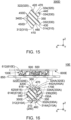
- an assembly (not shown) according to a fourth embodiment of the present invention comprises an electronic equipment 10C and a mating connector (not shown).
- the mating connector of the present embodiment has a structure same as that of the first embodiment. Accordingly, a detailed explanation thereabout is omitted. As for directions and orientations in the present embodiment, expressions same as those of the first embodiment will be used hereinbelow.
- the electronic equipment 10C of the present embodiment comprises a case 600 and a connector 100C.
- the case 600 of the present embodiment has a structure same as that of the first embodiment.
- Components of the case 600 of the present embodiment which are same as those of the case 600 of the first embodiment are referred by using reference signs same as those of the case 600 of the first embodiment, and a detailed explanation thereabout is omitted.
- the connector 100C of the present embodiment comprises a housing 200, a plurality of terminals 500 and a waterproofing member 300C.
- the housing 200 and the terminal 500 of the present embodiment have structures same as those of the first embodiment. Accordingly, a detailed explanation thereabout is omitted.
- the waterproofing member 300C of the present embodiment has a rectangular ring shape with rounded corners when viewed along the first direction.
- the waterproofing member 300C has an elastic property.
- the waterproofing member 300C is made of seamless rubber. Specifically, the waterproofing member 300C is a discrete member.
- the waterproofing member 300C is attached to the housing 200.
- the waterproofing member 300C is sandwiched by a bottom portion 210 and a back surface 614 of a main portion 610 in the first direction. More specifically, in the first direction, the waterproofing member 300C is sandwiched by the bottom portion 210 and the back surface 614 of the main portion 610 and is brought into contact with both of the bottom portion 210 and the back surface 614 of the main portion 610. In other words, the electronic equipment 10C forms a waterproof seal between the connector 100C and the case 600 by using the waterproofing member 300C.
- the waterproofing member 300C is sandwiched by the mating connector and a side portion 230 in the second direction perpendicular to the first direction when the connector 100C is mated with the mating connector.
- the assembly forms a waterproof seal between the connector 100C and the mating connector by using the waterproofing member 300C.
- the electronic equipment 10C of the present embodiment is configured so that the single waterproofing member 300C provides the waterproof seal between the connector 100C and the case 600 and provides the waterproof seal between the connector 100C and the mating connector.
- the single waterproofing member 300C is brought into contact with three members, namely the connector 100C, the case 600 and the mating connector, when the connector 100C is mated with the mating connector.
- the waterproofing member 300C has a first contact portion 310C, a second contact portion 320C, a third contact portion 330C and a fourth contact portion 340C.
- the first contact portion 310C faces outward in the first direction. Specifically, the first contact portion 310C faces downward in the up-down direction. As shown in Fig. 12 , the first contact portion 310C is pressed against and in contact with the bottom portion 210 in the first direction by the elasticity of the waterproofing member 300C.
- the second contact portion 320C faces outward in the first direction. Specifically, the second contact portion 320C faces upward in the up-down direction. As shown in Fig. 12 , the second contact portion 320C is pressed against and in contact with the back surface 614 of the main portion 610 in the first direction by the elasticity of the waterproofing member 300C.
- the third contact portion 330C faces outward in the second direction. As shown in Fig. 12 , the third contact portion 330C is in contact with the side portion 230 in the second direction. Referring to Fig. 12 , the third contact portion 330C is pressed against the side portion 230 in the second direction by the elasticity of the waterproofing member 300C upon the mating of the connector 100C with the mating connector.
- the fourth contact portion 340C of the present embodiment protrudes inward in the second direction beyond an opening 616.
- the fourth contact portion 340C has an obtuse apex 342.
- the fourth contact portion 340C is positioned at a first side of the waterproofing member 300C in the second direction.
- a circumferential length of the fourth contact portion 340C is shorter than a circumferential length of an abutment portion (not shown) of a mating housing (not shown) of the mating connector under an unmated state where the connector 100C and the mating connector are not mated with each other.
- a distance between the fourth contact portion 340C and the third contact portion 330C in the second direction under the unmated state is greater than a distance between the side portion 230 and the abutment portion in the second direction upon the mating of the connector 100C with the mating connector.
- the fourth contact portion 340C is pressed against and in contact with the mating connector in the second direction by the elasticity of the waterproofing member 300C upon the mating of the connector 100C with the mating connector. More specifically, the fourth contact portion 340C is pressed against and in contact with the abutment portion of the mating housing in the second direction by the elasticity of the waterproofing member 300C upon the mating of the connector 100C with the mating connector.
- the connector 100C is formed with a space 150C between the waterproofing member 300C and the side portion 230. Furthermore, the waterproofing member 300C has a recess portion 350C.
- the recess portion 350C of the present embodiment is recessed inward in the second direction.
- the recess portion 350C is positioned at a second side of the waterproofing member 300C which is opposite to the first side of the waterproofing member 300C at which the fourth contact portion 340C is positioned.
- the recess portion 350C is positioned away from the side portion 230.
- the recess portion 350C is positioned away from the side portion 230 in the second direction.
- the recess portion 350C is positioned closer to the second contact portion 320C than to the first contact portion 310C in the first direction.
- the space 150C is positioned between the recess portion 350C of the waterproofing member 300C and the side portion 230 of the housing 200.
- the waterproofing member 300C of the present embodiment has the recess portion 350C. This facilitates the fourth contact portion 340C to be moved outward in the second direction upon the mating of the connector 100C with the mating connector.
- the waterproofing member 300C of the present embodiment has a sandwiched portion 370.
- the sandwiched portion 370 extends outward in the second direction.
- the sandwiched portion 370 defines an outer end of the waterproofing member 300C in the second direction.
- the sandwiched portion 370 is sandwiched by the case 600 and the side portion 230 in the first direction. This enables the waterproofing member 300C to be reliably held by the electronic equipment 10C.
- an assembly (not shown) according to a fifth embodiment of the present invention comprises an electronic equipment 10D and a mating connector (not shown).
- the mating connector of the present embodiment has a structure same as that of the first embodiment. Accordingly, a detailed explanation thereabout is omitted. As for directions and orientations in the present embodiment, expressions same as those of the first embodiment will be used hereinbelow.
- the electronic equipment 10D of the present embodiment comprises a case 600 and a connector 100D.
- the case 600 of the present embodiment has a structure same as that of the first embodiment.
- Components of the case 600 of the present embodiment which are same as those of the case 600 of the first embodiment are referred by using reference signs same as those of the case 600 of the first embodiment, and a detailed explanation thereabout is omitted.
- the connector 100D of the present embodiment comprises a housing 200, a plurality of terminals 500 and a waterproofing member 300D.
- the housing 200 and the terminal 500 of the present embodiment have structures same as those of the first embodiment. Accordingly, a detailed explanation thereabout is omitted.
- the waterproofing member 300D of the present embodiment has a rectangular ring shape with rounded corners when viewed along the first direction.
- the waterproofing member 300D has an elastic property.
- the waterproofing member 300D is made of seamless rubber. Specifically, the waterproofing member 300D is a discrete member.
- the waterproofing member 300D is attached to the housing 200.
- the waterproofing member 300D of the present embodiment has a structure similar to the waterproofing member 300 of the first embodiment. Components of the waterproofing member 300D which are same as those of the waterproofing member 300 of the first embodiment are referred by using reference signs same as those of the waterproofing member 300 of the first embodiment, and a detailed explanation thereabout is omitted.
- the waterproofing member 300D in a state before the waterproofing member 300D is attached to the housing 200, the waterproofing member 300D has a shape which is mirror-symmetrical with respect to a plane perpendicular to the first direction.
- the waterproofing member 300D is sandwiched by a bottom portion 210 and a back surface 614 of a main portion 610 in the first direction. More specifically, in the first direction, the waterproofing member 300D is sandwiched by the bottom portion 210 and the back surface 614 of the main portion 610 and is brought into contact with both of the bottom portion 210 and the back surface 614 of the main portion 610. In other words, the electronic equipment 10D forms a waterproof seal between the connector 100D and the case 600 by using the waterproofing member 300D.
- the waterproofing member 300D is sandwiched by the mating connector and the side portion 230 in the second direction perpendicular to the first direction when the connector 100D is mated with the mating connector.
- the assembly forms a waterproof seal between the connector 100D and the mating connector by using the waterproofing member 300D.
- the electronic equipment 10D of the present embodiment is configured so that the single waterproofing member 300D provides the waterproof seal between the connector 100D and the case 600 and provides the waterproof seal between the connector 100D and the mating connector.
- the single waterproofing member 300D is brought into contact with three members, namely the connector 100D, the case 600 and the mating connector, when the connector 100D is mated with the mating connector.
- the waterproofing member 300D has two first contact portions 310, two second contact portions 320, two third contact portions 330 and a plurality of fourth contact portions 340D. More specifically, the number of the fourth contact portions 340D of the present embodiment is three. However, the present invention is not limited thereto. Specifically, the waterproofing member 300D should have at least one first contact portion 310, at least one second contact portion 320, at least one third contact portion 330 and at least one fourth contact portion 340D.
- the first contact portion 310, the second contact portion 320 and the third contact portion 330 of the present embodiment have structures same as those of the first embodiment. Accordingly, a detailed explanation thereabout is omitted.
- each of the fourth contact portions 340D of the present embodiment protrudes inward in the second direction beyond an opening 616.
- Each of the fourth contact portions 340D is positioned at a first side of the waterproofing member 300 in the second direction.
- a circumferential length of each of the fourth contact portions 340D is shorter than a circumferential length of an abutment portion (not shown) of a mating housing (not shown) of the mating connector under an unmated state where the connector 100D and the mating connector are not mated with each other.
- a distance between a third main contact portion 332 and any of the fourth contact portions 340D in the second direction under the unmated state is greater than a distance between the side portion 230 and the abutment portion in the second direction upon the mating of the connector 100D with the mating connector.
- a distance between a third sub contact portion 334 and any of the fourth contact portions 340D in the second direction under the unmated state is greater than the distance between the side portion 230 and the abutment portion in the second direction upon the mating of the connector 100D with the mating connector.
- each of the fourth contact portions 340D is pressed against and in contact with the mating connector in the second direction by the elasticity of the waterproofing member 300D upon the mating of the connector 100D with the mating connector. More specifically, each of the fourth contact portions 340D is pressed against and in contact with the abutment portion of the mating housing in the second direction by the elasticity of the waterproofing member 300D upon the mating of the connector 100D with the mating connector.
- the waterproofing member 300D has a first protrusion 410, a second protrusion 420, a third protrusion 430, a fourth protrusion 440 and a plurality of fifth protrusions 450D. More specifically, the number of the fifth protrusions 450D of the present embodiment is three.
- the first protrusion 410, the second protrusion 420, the third protrusion 430 and the fourth protrusion 440 of the present embodiment have structures same as those of the first embodiment. Accordingly, a detailed explanation thereabout is omitted.
- each of the fifth protrusions 450D of the present embodiment protrudes inward in the second direction.
- the fourth contact portions 340D are provided on the fifth protrusions 450D, respectively. Accordingly, the fourth contact portions 340D are hardly dragged to be moved downward by the mating connector upon the mating of the connector 100D with the mating connector. Specifically, each of the fourth contact portions 340D is easily moved outward in the second direction upon the mating of the connector 100D with the mating connector.
- the mating connector is easily inserted into the connector 100D upon the mating of the connector 100 with the mating connector, and the assembly can maintain the waterproof seal between the connector 100D and the mating connector under a mated state where the connector 100D is mated with the mating connector.
- a recess portion 350 of the present embodiment is positioned at a second side of the waterproofing member 300D which is opposite to the first side of the waterproofing member 300D at which each of the fourth contact portions 340D is positioned.
- the waterproofing member 300D of the present embodiment has the recess portion 350. This facilitates each of the fourth contact portions 340D to be moved outward in the second direction upon the mating of the connector 100D with the mating connector.
- an assembly (not shown) according to a sixth embodiment of the present invention comprises an electronic equipment 10E and a mating connector (not shown).
- the mating connector of the present embodiment has a structure same as that of the first embodiment. Accordingly, a detailed explanation thereabout is omitted. As for directions and orientations in the present embodiment, expressions same as those of the first embodiment will be used hereinbelow.
- the electronic equipment 10E of the present embodiment comprises a case 600E and a connector 100E.
- the case 600E of the present embodiment is made of resin.
- the case 600E has a main portion 610E.
- the main portion 610E of the present embodiment has a flat-plate shape perpendicular to the first direction.
- the main portion 610E has a top surface 612 and a back surface 614E in the first direction.
- the main portion 610E is provided with an opening 616.
- the opening 616 pierces the main portion 610E in the first direction.
- the case 600E has a ditch 615.
- the ditch 615 is recessed outward in the first direction. More specifically, the ditch 615 is recessed upward in the up-down direction.
- the ditch 615 forms a part of the back surface 614E.
- the ditch 615 has a receiving portion 620. In other words, the case 600E has the receiving portion 620.
- the receiving portion 620 faces inward in the second direction.
- the connector 100E of the present embodiment comprises a housing 200, a plurality of terminals 500 and a waterproofing member 300E.
- the housing 200 and the terminal 500 of the present embodiment have structures same as those of the first embodiment. Accordingly, a detailed explanation thereabout is omitted.
- a bottom portion 210 of the housing 200 is positioned away from the back surface 614E of the main portion 610E in the first direction.
- a side portion 230 of the housing 200 extends from the bottom portion 210 toward the back surface 614E of the main portion 610E in the first direction.
- the electronic equipment 10E is formed with a gap 170E between the case 600E and the side portion 230 of the housing 200.
- the back surface 614E of the main portion 610E and the side portion 230 of the housing 200 are spaced away from each other in the first direction.
- the waterproofing member 300E of the present embodiment has a rectangular ring shape with rounded corners when viewed along the first direction.
- the waterproofing member 300E has an elastic property.
- the waterproofing member 300E is made of seamless rubber. Specifically, the waterproofing member 300E is a discrete member.
- the waterproofing member 300E is attached to the housing 200.
- the waterproofing member 300E of the present embodiment has a structure similar to the waterproofing member 300A of the second embodiment. Components of the waterproofing member 300E which are same as those of the waterproofing member 300A of the second embodiment are referred by using reference signs same as those of the waterproofing member 300A of the second embodiment, and a detailed explanation thereabout is omitted.
- the waterproofing member 300E is sandwiched by the bottom portion 210 and the back surface 614E of the main portion 610E in the first direction. More specifically, in the first direction, the waterproofing member 300E is sandwiched by the bottom portion 210 and the back surface 614E of the main portion 610E and is brought into contact with both of the bottom portion 210 and the back surface 614E of the main portion 610E. In other words, the electronic equipment 10E forms a waterproof seal between the connector 100E and the case 600E by using the waterproofing member 300E.
- the waterproofing member 300E is sandwiched by the mating connector and the side portion 230 in the second direction perpendicular to the first direction when the connector 100E is mated with the mating connector.
- the assembly forms a waterproof seal between the connector 100E and the mating connector by using the waterproofing member 300E.
- the electronic equipment 10E of the present embodiment is configured so that the single waterproofing member 300E provides the waterproof seal between the connector 100E and the case 600E and provides the waterproof seal between the connector 100E and the mating connector.
- the single waterproofing member 300E is brought into contact with three members, namely the connector 100E, the case 600E and the mating connector, when the connector 100E is mated with the mating connector.
- the waterproofing member 300E has two first contact portions 310A, two second contact portions 320E, two third contact portions 330A and a fourth contact portion 340.
- the present invention is not limited thereto.
- the waterproofing member 300E should have at least one first contact portion 310A, at least one second contact portion 320E, at least one third contact portion 330A and at least one fourth contact portion 340.
- the first contact portion 310A, the third contact portion 330A and the fourth contact portion 340 of the present embodiment have structures same as those of the second embodiment. Accordingly, a detailed explanation thereabout is omitted.
- the second contact portions 320E of the present embodiment are positioned away from each other in the second direction in a state before the waterproofing member 300E is attached to the housing 200. As shown in Fig. 16 , the second contact portions 320E are positioned away from each other in the second direction under a state where the waterproofing member 300E is attached to the housing 200.
- each of the second contact portions 320E is pressed against and in contact with the back surface 614E of the main portion 610E in the first direction by the elasticity of the waterproofing member 300E.
- the second contact portions 320E include a second main contact portion 322E and a second sub contact portion 324A.
- the second main contact portion 322E is pressed against and in contact with the ditch 615 in the first direction by the elasticity of the waterproofing member 300E.
- the second main contact portion 322E and the second sub contact portion 324A of the present embodiment have structures same as those of the second main contact portion 322 and the second sub contact portion 324A of the second embodiment. Accordingly, a detailed explanation thereabout is omitted.
- the waterproofing member 300E has a first protrusion 410, a second protrusion 420E, a third protrusion 430A, a fourth protrusion 440A and a fifth protrusion 450.
- the first protrusion 410, the third protrusion 430A, the fourth protrusion 440A and the fifth protrusion 450 have structures same as those of the second embodiment. Accordingly, a detailed explanation thereabout is omitted.
- the second main contact portion 322E of the second contact portions 320E is provided on the second protrusion 420E.
- the second protrusion 420E is received in the ditch 615 under the state where the waterproofing member 300E is attached to the housing 200.
- the second protrusion 420E is provided with a received portion 360.
- the waterproofing member 300E has the received portion 360.
- the received portion 360 of the present embodiment faces outward in the second direction.
- the received portion 360 neighbors to the second main contact portion 322E of the second contact portions 320E in the second direction.
- the received portion 360 is provided at a location between the second main contact portion 322E of the second contact portions 320E and the side portion 230 in the second direction. Referring to Fig. 16 , the received portion 360 is pressed against the receiving portion 620 upon the mating of the connector 100E with the mating connector. This can form a reliable waterproof seal between the case 600E and the housing 200 in the electronic equipment 10E of the present embodiment.
- a fit portion 442A of the present embodiment enters into the gap 170E and is brought into close contact with both of the back surface 614E of the case 600E and the side portion 230. This enhances the waterproof seal between the connector 100E and the case 600E.
Landscapes
- Engineering & Computer Science (AREA)
- Microelectronics & Electronic Packaging (AREA)
- Chemical & Material Sciences (AREA)
- Dispersion Chemistry (AREA)
- Connector Housings Or Holding Contact Members (AREA)
- Coupling Device And Connection With Printed Circuit (AREA)
Applications Claiming Priority (1)
| Application Number | Priority Date | Filing Date | Title |
|---|---|---|---|
| JP2021075537A JP7608260B2 (ja) | 2021-04-28 | 2021-04-28 | 電子機器 |
Publications (2)
| Publication Number | Publication Date |
|---|---|
| EP4084234A1 EP4084234A1 (en) | 2022-11-02 |
| EP4084234B1 true EP4084234B1 (en) | 2023-12-20 |
Family
ID=80930138
Family Applications (1)
| Application Number | Title | Priority Date | Filing Date |
|---|---|---|---|
| EP22163795.2A Active EP4084234B1 (en) | 2021-04-28 | 2022-03-23 | Electronic equipment |
Country Status (4)
| Country | Link |
|---|---|
| US (1) | US11804669B2 (https=) |
| EP (1) | EP4084234B1 (https=) |
| JP (1) | JP7608260B2 (https=) |
| CN (1) | CN115249916B (https=) |
Families Citing this family (2)
| Publication number | Priority date | Publication date | Assignee | Title |
|---|---|---|---|---|
| US12567686B2 (en) * | 2023-04-18 | 2026-03-03 | Cisco Technology, Inc. | Termination of cables for a connector |
| US20250202158A1 (en) * | 2023-12-19 | 2025-06-19 | Te Connectivity Solutions Gmbh | Peripheral Seal with Sloped Ribs |
Family Cites Families (26)
| Publication number | Priority date | Publication date | Assignee | Title |
|---|---|---|---|---|
| JPS5986754A (ja) | 1982-11-08 | 1984-05-19 | Honda Motor Co Ltd | シ−ルリング |
| JPS6218661U (https=) | 1985-07-17 | 1987-02-04 | ||
| US4944688A (en) * | 1989-09-25 | 1990-07-31 | Amp Incorporated | Programmable sealed connector |
| JP2542639Y2 (ja) * | 1990-11-27 | 1997-07-30 | 住友電装株式会社 | コネクタ |
| US5492487A (en) * | 1993-06-07 | 1996-02-20 | Ford Motor Company | Seal retention for an electrical connector assembly |
| JPH08250198A (ja) * | 1995-03-14 | 1996-09-27 | Sumitomo Wiring Syst Ltd | コネクタにおけるシール構造 |
| US6045383A (en) * | 1996-05-17 | 2000-04-04 | The Whitaker Corporation | Sealing member for waterproof connector |
| JP2001110520A (ja) * | 1999-10-04 | 2001-04-20 | Sumitomo Wiring Syst Ltd | コネクタ |
| US6244886B1 (en) * | 2000-01-24 | 2001-06-12 | Delphi Technologies, Inc. | Electrical connection system having force distribution seal |
| JP3478385B2 (ja) * | 2000-05-11 | 2003-12-15 | 住友電装株式会社 | 防水コネクタ |
| JP2002195411A (ja) | 2001-11-15 | 2002-07-10 | Nok Corp | ガスケット |
| JP4900590B2 (ja) | 2007-03-02 | 2012-03-21 | Nok株式会社 | 電子機器の防水構造 |
| US7611369B2 (en) * | 2007-08-01 | 2009-11-03 | Sumitomo Wiring Systems, Ltd | Connector |
| JP5072781B2 (ja) | 2008-09-04 | 2012-11-14 | 住友電装株式会社 | コネクタ |
| JP5428730B2 (ja) * | 2009-10-13 | 2014-02-26 | 住友電装株式会社 | 防水コネクタ |
| JP4922424B2 (ja) * | 2010-03-05 | 2012-04-25 | 日本航空電子工業株式会社 | 防水コネクタ |
| JP6180714B2 (ja) | 2012-08-21 | 2017-08-16 | Nok株式会社 | 機器ケースの開閉部分の防水構造 |
| JP2014107122A (ja) | 2012-11-28 | 2014-06-09 | Jst Mfg Co Ltd | 防水仕様のコネクタ |
| JP5985971B2 (ja) | 2012-12-05 | 2016-09-06 | 日本航空電子工業株式会社 | 防水コネクタ |
| JP6106443B2 (ja) * | 2013-01-28 | 2017-03-29 | 矢崎総業株式会社 | シール部材及びシール構造 |
| JP6247604B2 (ja) | 2014-06-24 | 2017-12-13 | 日本航空電子工業株式会社 | 防水コネクタ |
| JP5835434B1 (ja) * | 2014-07-31 | 2015-12-24 | 第一精工株式会社 | 防水コネクタ |
| KR101651654B1 (ko) | 2015-09-07 | 2016-09-05 | 주식회사 신화콘텍 | 패브릭 모듈용 방수 커넥터 |
| KR102589304B1 (ko) | 2016-06-22 | 2023-10-16 | 삼성전자주식회사 | 커넥터 장치 및 이를 구비한 전자 장치 |
| JP2018174037A (ja) * | 2017-03-31 | 2018-11-08 | タイコエレクトロニクスジャパン合同会社 | シール部材および電気コネクタ |
| WO2019077722A1 (ja) | 2017-10-19 | 2019-04-25 | 三菱電機株式会社 | 防水型コネクタおよびその組立方法 |
-
2021
- 2021-04-28 JP JP2021075537A patent/JP7608260B2/ja active Active
-
2022
- 2022-03-22 US US17/700,619 patent/US11804669B2/en active Active
- 2022-03-23 EP EP22163795.2A patent/EP4084234B1/en active Active
- 2022-03-29 CN CN202210321072.0A patent/CN115249916B/zh active Active
Also Published As
| Publication number | Publication date |
|---|---|
| US20220352671A1 (en) | 2022-11-03 |
| US11804669B2 (en) | 2023-10-31 |
| JP7608260B2 (ja) | 2025-01-06 |
| CN115249916B (zh) | 2025-04-08 |
| CN115249916A (zh) | 2022-10-28 |
| JP2022169856A (ja) | 2022-11-10 |
| EP4084234A1 (en) | 2022-11-02 |
Similar Documents
| Publication | Publication Date | Title |
|---|---|---|
| EP4084234B1 (en) | Electronic equipment | |
| CN1196234C (zh) | 带有经改进的导向部分的连接器 | |
| US6935893B1 (en) | Electrical connector with terminal position assurance device | |
| CN1115757C (zh) | 带开关的同轴连接器 | |
| CN106663903A (zh) | 具有浮动机构的同轴连接器 | |
| CN1324770C (zh) | 带开关的同轴连接器 | |
| CN113839258B (zh) | 连接器 | |
| US6814605B2 (en) | Connector having a shielding shell provided with a locking portion | |
| EP4170830B1 (en) | Waterproof connector | |
| CN115413389B (zh) | 连接器装置 | |
| US12494600B2 (en) | Terminal and a connector | |
| CN219843200U (zh) | 连接器、连接器装置和车辆 | |
| WO2025218035A1 (zh) | 连接器及连接器组件 | |
| US20240120693A1 (en) | Connector with floating mechanism | |
| CN211530237U (zh) | 耐大电流防瞬断针式连接器 | |
| KR101922566B1 (ko) | 전기 커넥터 및 전기 커넥터 조립체 | |
| CN219286692U (zh) | 电连接器组件、连接器端子及插头端子 | |
| CN221226614U (zh) | 一种用于电力系统的连接器 | |
| CN224217761U (zh) | 母座连接器 | |
| US20240235115A1 (en) | Electrical connector with floating mechanism | |
| US7314381B2 (en) | Electric component having connector attached to case via seal member | |
| KR20260036723A (ko) | 플로팅 다접점 소켓 유동 동축 커넥터 | |
| CN118630507A (zh) | 防止触点从结构脱落的构造 | |
| CN120834458A (zh) | 电连接装置 | |
| CN111262076A (zh) | 耐大电流防瞬断针式连接器 |
Legal Events
| Date | Code | Title | Description |
|---|---|---|---|
| PUAI | Public reference made under article 153(3) epc to a published international application that has entered the european phase |
Free format text: ORIGINAL CODE: 0009012 |
|
| STAA | Information on the status of an ep patent application or granted ep patent |
Free format text: STATUS: THE APPLICATION HAS BEEN PUBLISHED |
|
| AK | Designated contracting states |
Kind code of ref document: A1 Designated state(s): AL AT BE BG CH CY CZ DE DK EE ES FI FR GB GR HR HU IE IS IT LI LT LU LV MC MK MT NL NO PL PT RO RS SE SI SK SM TR |
|
| STAA | Information on the status of an ep patent application or granted ep patent |
Free format text: STATUS: REQUEST FOR EXAMINATION WAS MADE |
|
| 17P | Request for examination filed |
Effective date: 20230406 |
|
| RBV | Designated contracting states (corrected) |
Designated state(s): AL AT BE BG CH CY CZ DE DK EE ES FI FR GB GR HR HU IE IS IT LI LT LU LV MC MK MT NL NO PL PT RO RS SE SI SK SM TR |
|
| GRAP | Despatch of communication of intention to grant a patent |
Free format text: ORIGINAL CODE: EPIDOSNIGR1 |
|
| STAA | Information on the status of an ep patent application or granted ep patent |
Free format text: STATUS: GRANT OF PATENT IS INTENDED |
|
| INTG | Intention to grant announced |
Effective date: 20230714 |
|
| GRAS | Grant fee paid |
Free format text: ORIGINAL CODE: EPIDOSNIGR3 |
|
| GRAA | (expected) grant |
Free format text: ORIGINAL CODE: 0009210 |
|
| STAA | Information on the status of an ep patent application or granted ep patent |
Free format text: STATUS: THE PATENT HAS BEEN GRANTED |
|
| AK | Designated contracting states |
Kind code of ref document: B1 Designated state(s): AL AT BE BG CH CY CZ DE DK EE ES FI FR GB GR HR HU IE IS IT LI LT LU LV MC MK MT NL NO PL PT RO RS SE SI SK SM TR |
|
| REG | Reference to a national code |
Ref country code: GB Ref legal event code: FG4D |
|
| REG | Reference to a national code |
Ref country code: CH Ref legal event code: EP |
|
| REG | Reference to a national code |
Ref country code: DE Ref legal event code: R096 Ref document number: 602022001337 Country of ref document: DE |
|
| REG | Reference to a national code |
Ref country code: IE Ref legal event code: FG4D |
|
| PG25 | Lapsed in a contracting state [announced via postgrant information from national office to epo] |
Ref country code: GR Free format text: LAPSE BECAUSE OF FAILURE TO SUBMIT A TRANSLATION OF THE DESCRIPTION OR TO PAY THE FEE WITHIN THE PRESCRIBED TIME-LIMIT Effective date: 20240321 |
|
| REG | Reference to a national code |
Ref country code: LT Ref legal event code: MG9D |
|
| PG25 | Lapsed in a contracting state [announced via postgrant information from national office to epo] |
Ref country code: LT Free format text: LAPSE BECAUSE OF FAILURE TO SUBMIT A TRANSLATION OF THE DESCRIPTION OR TO PAY THE FEE WITHIN THE PRESCRIBED TIME-LIMIT Effective date: 20231220 |
|
| REG | Reference to a national code |
Ref country code: NL Ref legal event code: MP Effective date: 20231220 |
|
| PG25 | Lapsed in a contracting state [announced via postgrant information from national office to epo] |
Ref country code: ES Free format text: LAPSE BECAUSE OF FAILURE TO SUBMIT A TRANSLATION OF THE DESCRIPTION OR TO PAY THE FEE WITHIN THE PRESCRIBED TIME-LIMIT Effective date: 20231220 |
|
| PG25 | Lapsed in a contracting state [announced via postgrant information from national office to epo] |
Ref country code: LT Free format text: LAPSE BECAUSE OF FAILURE TO SUBMIT A TRANSLATION OF THE DESCRIPTION OR TO PAY THE FEE WITHIN THE PRESCRIBED TIME-LIMIT Effective date: 20231220 Ref country code: GR Free format text: LAPSE BECAUSE OF FAILURE TO SUBMIT A TRANSLATION OF THE DESCRIPTION OR TO PAY THE FEE WITHIN THE PRESCRIBED TIME-LIMIT Effective date: 20240321 Ref country code: FI Free format text: LAPSE BECAUSE OF FAILURE TO SUBMIT A TRANSLATION OF THE DESCRIPTION OR TO PAY THE FEE WITHIN THE PRESCRIBED TIME-LIMIT Effective date: 20231220 Ref country code: ES Free format text: LAPSE BECAUSE OF FAILURE TO SUBMIT A TRANSLATION OF THE DESCRIPTION OR TO PAY THE FEE WITHIN THE PRESCRIBED TIME-LIMIT Effective date: 20231220 Ref country code: BG Free format text: LAPSE BECAUSE OF FAILURE TO SUBMIT A TRANSLATION OF THE DESCRIPTION OR TO PAY THE FEE WITHIN THE PRESCRIBED TIME-LIMIT Effective date: 20240320 |
|
| REG | Reference to a national code |
Ref country code: AT Ref legal event code: MK05 Ref document number: 1643262 Country of ref document: AT Kind code of ref document: T Effective date: 20231220 |
|
| PG25 | Lapsed in a contracting state [announced via postgrant information from national office to epo] |
Ref country code: NL Free format text: LAPSE BECAUSE OF FAILURE TO SUBMIT A TRANSLATION OF THE DESCRIPTION OR TO PAY THE FEE WITHIN THE PRESCRIBED TIME-LIMIT Effective date: 20231220 |
|
| PG25 | Lapsed in a contracting state [announced via postgrant information from national office to epo] |
Ref country code: SE Free format text: LAPSE BECAUSE OF FAILURE TO SUBMIT A TRANSLATION OF THE DESCRIPTION OR TO PAY THE FEE WITHIN THE PRESCRIBED TIME-LIMIT Effective date: 20231220 Ref country code: RS Free format text: LAPSE BECAUSE OF FAILURE TO SUBMIT A TRANSLATION OF THE DESCRIPTION OR TO PAY THE FEE WITHIN THE PRESCRIBED TIME-LIMIT Effective date: 20231220 Ref country code: NO Free format text: LAPSE BECAUSE OF FAILURE TO SUBMIT A TRANSLATION OF THE DESCRIPTION OR TO PAY THE FEE WITHIN THE PRESCRIBED TIME-LIMIT Effective date: 20240320 Ref country code: NL Free format text: LAPSE BECAUSE OF FAILURE TO SUBMIT A TRANSLATION OF THE DESCRIPTION OR TO PAY THE FEE WITHIN THE PRESCRIBED TIME-LIMIT Effective date: 20231220 Ref country code: LV Free format text: LAPSE BECAUSE OF FAILURE TO SUBMIT A TRANSLATION OF THE DESCRIPTION OR TO PAY THE FEE WITHIN THE PRESCRIBED TIME-LIMIT Effective date: 20231220 Ref country code: HR Free format text: LAPSE BECAUSE OF FAILURE TO SUBMIT A TRANSLATION OF THE DESCRIPTION OR TO PAY THE FEE WITHIN THE PRESCRIBED TIME-LIMIT Effective date: 20231220 |
|
| PG25 | Lapsed in a contracting state [announced via postgrant information from national office to epo] |
Ref country code: IS Free format text: LAPSE BECAUSE OF FAILURE TO SUBMIT A TRANSLATION OF THE DESCRIPTION OR TO PAY THE FEE WITHIN THE PRESCRIBED TIME-LIMIT Effective date: 20240420 |
|
| PG25 | Lapsed in a contracting state [announced via postgrant information from national office to epo] |
Ref country code: CZ Free format text: LAPSE BECAUSE OF FAILURE TO SUBMIT A TRANSLATION OF THE DESCRIPTION OR TO PAY THE FEE WITHIN THE PRESCRIBED TIME-LIMIT Effective date: 20231220 Ref country code: AT Free format text: LAPSE BECAUSE OF FAILURE TO SUBMIT A TRANSLATION OF THE DESCRIPTION OR TO PAY THE FEE WITHIN THE PRESCRIBED TIME-LIMIT Effective date: 20231220 |
|
| PG25 | Lapsed in a contracting state [announced via postgrant information from national office to epo] |
Ref country code: SK Free format text: LAPSE BECAUSE OF FAILURE TO SUBMIT A TRANSLATION OF THE DESCRIPTION OR TO PAY THE FEE WITHIN THE PRESCRIBED TIME-LIMIT Effective date: 20231220 |
|
| PG25 | Lapsed in a contracting state [announced via postgrant information from national office to epo] |
Ref country code: SM Free format text: LAPSE BECAUSE OF FAILURE TO SUBMIT A TRANSLATION OF THE DESCRIPTION OR TO PAY THE FEE WITHIN THE PRESCRIBED TIME-LIMIT Effective date: 20231220 Ref country code: SK Free format text: LAPSE BECAUSE OF FAILURE TO SUBMIT A TRANSLATION OF THE DESCRIPTION OR TO PAY THE FEE WITHIN THE PRESCRIBED TIME-LIMIT Effective date: 20231220 Ref country code: RO Free format text: LAPSE BECAUSE OF FAILURE TO SUBMIT A TRANSLATION OF THE DESCRIPTION OR TO PAY THE FEE WITHIN THE PRESCRIBED TIME-LIMIT Effective date: 20231220 Ref country code: IT Free format text: LAPSE BECAUSE OF FAILURE TO SUBMIT A TRANSLATION OF THE DESCRIPTION OR TO PAY THE FEE WITHIN THE PRESCRIBED TIME-LIMIT Effective date: 20231220 Ref country code: IS Free format text: LAPSE BECAUSE OF FAILURE TO SUBMIT A TRANSLATION OF THE DESCRIPTION OR TO PAY THE FEE WITHIN THE PRESCRIBED TIME-LIMIT Effective date: 20240420 Ref country code: EE Free format text: LAPSE BECAUSE OF FAILURE TO SUBMIT A TRANSLATION OF THE DESCRIPTION OR TO PAY THE FEE WITHIN THE PRESCRIBED TIME-LIMIT Effective date: 20231220 Ref country code: CZ Free format text: LAPSE BECAUSE OF FAILURE TO SUBMIT A TRANSLATION OF THE DESCRIPTION OR TO PAY THE FEE WITHIN THE PRESCRIBED TIME-LIMIT Effective date: 20231220 Ref country code: AT Free format text: LAPSE BECAUSE OF FAILURE TO SUBMIT A TRANSLATION OF THE DESCRIPTION OR TO PAY THE FEE WITHIN THE PRESCRIBED TIME-LIMIT Effective date: 20231220 |
|
| PG25 | Lapsed in a contracting state [announced via postgrant information from national office to epo] |
Ref country code: PL Free format text: LAPSE BECAUSE OF FAILURE TO SUBMIT A TRANSLATION OF THE DESCRIPTION OR TO PAY THE FEE WITHIN THE PRESCRIBED TIME-LIMIT Effective date: 20231220 Ref country code: PT Free format text: LAPSE BECAUSE OF FAILURE TO SUBMIT A TRANSLATION OF THE DESCRIPTION OR TO PAY THE FEE WITHIN THE PRESCRIBED TIME-LIMIT Effective date: 20240422 |
|
| PG25 | Lapsed in a contracting state [announced via postgrant information from national office to epo] |
Ref country code: PT Free format text: LAPSE BECAUSE OF FAILURE TO SUBMIT A TRANSLATION OF THE DESCRIPTION OR TO PAY THE FEE WITHIN THE PRESCRIBED TIME-LIMIT Effective date: 20240422 Ref country code: PL Free format text: LAPSE BECAUSE OF FAILURE TO SUBMIT A TRANSLATION OF THE DESCRIPTION OR TO PAY THE FEE WITHIN THE PRESCRIBED TIME-LIMIT Effective date: 20231220 |
|
| REG | Reference to a national code |
Ref country code: DE Ref legal event code: R097 Ref document number: 602022001337 Country of ref document: DE |
|
| PG25 | Lapsed in a contracting state [announced via postgrant information from national office to epo] |
Ref country code: DK Free format text: LAPSE BECAUSE OF FAILURE TO SUBMIT A TRANSLATION OF THE DESCRIPTION OR TO PAY THE FEE WITHIN THE PRESCRIBED TIME-LIMIT Effective date: 20231220 |
|
| PLBE | No opposition filed within time limit |
Free format text: ORIGINAL CODE: 0009261 |
|
| STAA | Information on the status of an ep patent application or granted ep patent |
Free format text: STATUS: NO OPPOSITION FILED WITHIN TIME LIMIT |
|
| PG25 | Lapsed in a contracting state [announced via postgrant information from national office to epo] |
Ref country code: SI Free format text: LAPSE BECAUSE OF FAILURE TO SUBMIT A TRANSLATION OF THE DESCRIPTION OR TO PAY THE FEE WITHIN THE PRESCRIBED TIME-LIMIT Effective date: 20231220 |
|
| RAP4 | Party data changed (patent owner data changed or rights of a patent transferred) |
Owner name: JAPAN AVIATION ELECTRONICS INDUSTRY, LIMITED |
|
| PG25 | Lapsed in a contracting state [announced via postgrant information from national office to epo] |
Ref country code: SI Free format text: LAPSE BECAUSE OF FAILURE TO SUBMIT A TRANSLATION OF THE DESCRIPTION OR TO PAY THE FEE WITHIN THE PRESCRIBED TIME-LIMIT Effective date: 20231220 Ref country code: DK Free format text: LAPSE BECAUSE OF FAILURE TO SUBMIT A TRANSLATION OF THE DESCRIPTION OR TO PAY THE FEE WITHIN THE PRESCRIBED TIME-LIMIT Effective date: 20231220 |
|
| PG25 | Lapsed in a contracting state [announced via postgrant information from national office to epo] |
Ref country code: LU Free format text: LAPSE BECAUSE OF NON-PAYMENT OF DUE FEES Effective date: 20240323 |
|
| PG25 | Lapsed in a contracting state [announced via postgrant information from national office to epo] |
Ref country code: MC Free format text: LAPSE BECAUSE OF FAILURE TO SUBMIT A TRANSLATION OF THE DESCRIPTION OR TO PAY THE FEE WITHIN THE PRESCRIBED TIME-LIMIT Effective date: 20231220 |
|
| 26N | No opposition filed |
Effective date: 20240923 |
|
| PG25 | Lapsed in a contracting state [announced via postgrant information from national office to epo] |
Ref country code: MC Free format text: LAPSE BECAUSE OF FAILURE TO SUBMIT A TRANSLATION OF THE DESCRIPTION OR TO PAY THE FEE WITHIN THE PRESCRIBED TIME-LIMIT Effective date: 20231220 Ref country code: LU Free format text: LAPSE BECAUSE OF NON-PAYMENT OF DUE FEES Effective date: 20240323 |
|
| REG | Reference to a national code |
Ref country code: BE Ref legal event code: MM Effective date: 20240331 |
|
| PG25 | Lapsed in a contracting state [announced via postgrant information from national office to epo] |
Ref country code: BE Free format text: LAPSE BECAUSE OF NON-PAYMENT OF DUE FEES Effective date: 20240331 |
|
| PG25 | Lapsed in a contracting state [announced via postgrant information from national office to epo] |
Ref country code: IE Free format text: LAPSE BECAUSE OF NON-PAYMENT OF DUE FEES Effective date: 20240323 |
|
| PG25 | Lapsed in a contracting state [announced via postgrant information from national office to epo] |
Ref country code: IE Free format text: LAPSE BECAUSE OF NON-PAYMENT OF DUE FEES Effective date: 20240323 Ref country code: BE Free format text: LAPSE BECAUSE OF NON-PAYMENT OF DUE FEES Effective date: 20240331 |
|
| PG25 | Lapsed in a contracting state [announced via postgrant information from national office to epo] |
Ref country code: CY Free format text: LAPSE BECAUSE OF FAILURE TO SUBMIT A TRANSLATION OF THE DESCRIPTION OR TO PAY THE FEE WITHIN THE PRESCRIBED TIME-LIMIT; INVALID AB INITIO Effective date: 20220323 |
|
| REG | Reference to a national code |
Ref country code: CH Ref legal event code: H13 Free format text: ST27 STATUS EVENT CODE: U-0-0-H10-H13 (AS PROVIDED BY THE NATIONAL OFFICE) Effective date: 20251023 |
|
| PG25 | Lapsed in a contracting state [announced via postgrant information from national office to epo] |
Ref country code: TR Free format text: LAPSE BECAUSE OF FAILURE TO SUBMIT A TRANSLATION OF THE DESCRIPTION OR TO PAY THE FEE WITHIN THE PRESCRIBED TIME-LIMIT Effective date: 20231220 |
|
| PG25 | Lapsed in a contracting state [announced via postgrant information from national office to epo] |
Ref country code: CH Free format text: LAPSE BECAUSE OF NON-PAYMENT OF DUE FEES Effective date: 20250331 |
|
| PGFP | Annual fee paid to national office [announced via postgrant information from national office to epo] |
Ref country code: DE Payment date: 20260128 Year of fee payment: 5 |
|
| PGFP | Annual fee paid to national office [announced via postgrant information from national office to epo] |
Ref country code: FR Payment date: 20260209 Year of fee payment: 5 |