EP4079524A2 - Kopfsystem, flüssigkeitsausstossvorrichtung, druckvorrichtung und verfahren zum zuführen von flüssigkeit - Google Patents
Kopfsystem, flüssigkeitsausstossvorrichtung, druckvorrichtung und verfahren zum zuführen von flüssigkeit Download PDFInfo
- Publication number
- EP4079524A2 EP4079524A2 EP22164502.1A EP22164502A EP4079524A2 EP 4079524 A2 EP4079524 A2 EP 4079524A2 EP 22164502 A EP22164502 A EP 22164502A EP 4079524 A2 EP4079524 A2 EP 4079524A2
- Authority
- EP
- European Patent Office
- Prior art keywords
- coolant
- sub
- tank
- ink
- liquid
- Prior art date
- Legal status (The legal status is an assumption and is not a legal conclusion. Google has not performed a legal analysis and makes no representation as to the accuracy of the status listed.)
- Granted
Links
Images




Classifications
-
- B—PERFORMING OPERATIONS; TRANSPORTING
- B41—PRINTING; LINING MACHINES; TYPEWRITERS; STAMPS
- B41J—TYPEWRITERS; SELECTIVE PRINTING MECHANISMS, i.e. MECHANISMS PRINTING OTHERWISE THAN FROM A FORME; CORRECTION OF TYPOGRAPHICAL ERRORS
- B41J29/00—Details of, or accessories for, typewriters or selective printing mechanisms not otherwise provided for
- B41J29/377—Cooling or ventilating arrangements
-
- B—PERFORMING OPERATIONS; TRANSPORTING
- B41—PRINTING; LINING MACHINES; TYPEWRITERS; STAMPS
- B41J—TYPEWRITERS; SELECTIVE PRINTING MECHANISMS, i.e. MECHANISMS PRINTING OTHERWISE THAN FROM A FORME; CORRECTION OF TYPOGRAPHICAL ERRORS
- B41J2/00—Typewriters or selective printing mechanisms characterised by the printing or marking process for which they are designed
- B41J2/005—Typewriters or selective printing mechanisms characterised by the printing or marking process for which they are designed characterised by bringing liquid or particles selectively into contact with a printing material
- B41J2/01—Ink jet
- B41J2/17—Ink jet characterised by ink handling
- B41J2/175—Ink supply systems ; Circuit parts therefor
- B41J2/17503—Ink cartridges
- B41J2/17513—Inner structure
-
- B—PERFORMING OPERATIONS; TRANSPORTING
- B41—PRINTING; LINING MACHINES; TYPEWRITERS; STAMPS
- B41J—TYPEWRITERS; SELECTIVE PRINTING MECHANISMS, i.e. MECHANISMS PRINTING OTHERWISE THAN FROM A FORME; CORRECTION OF TYPOGRAPHICAL ERRORS
- B41J2/00—Typewriters or selective printing mechanisms characterised by the printing or marking process for which they are designed
- B41J2/005—Typewriters or selective printing mechanisms characterised by the printing or marking process for which they are designed characterised by bringing liquid or particles selectively into contact with a printing material
- B41J2/01—Ink jet
- B41J2/135—Nozzles
- B41J2/14—Structure thereof only for on-demand ink jet heads
- B41J2/14201—Structure of print heads with piezoelectric elements
- B41J2/14233—Structure of print heads with piezoelectric elements of film type, deformed by bending and disposed on a diaphragm
-
- B—PERFORMING OPERATIONS; TRANSPORTING
- B41—PRINTING; LINING MACHINES; TYPEWRITERS; STAMPS
- B41J—TYPEWRITERS; SELECTIVE PRINTING MECHANISMS, i.e. MECHANISMS PRINTING OTHERWISE THAN FROM A FORME; CORRECTION OF TYPOGRAPHICAL ERRORS
- B41J2/00—Typewriters or selective printing mechanisms characterised by the printing or marking process for which they are designed
- B41J2/005—Typewriters or selective printing mechanisms characterised by the printing or marking process for which they are designed characterised by bringing liquid or particles selectively into contact with a printing material
- B41J2/01—Ink jet
- B41J2/17—Ink jet characterised by ink handling
- B41J2/175—Ink supply systems ; Circuit parts therefor
-
- B—PERFORMING OPERATIONS; TRANSPORTING
- B41—PRINTING; LINING MACHINES; TYPEWRITERS; STAMPS
- B41J—TYPEWRITERS; SELECTIVE PRINTING MECHANISMS, i.e. MECHANISMS PRINTING OTHERWISE THAN FROM A FORME; CORRECTION OF TYPOGRAPHICAL ERRORS
- B41J2/00—Typewriters or selective printing mechanisms characterised by the printing or marking process for which they are designed
- B41J2/005—Typewriters or selective printing mechanisms characterised by the printing or marking process for which they are designed characterised by bringing liquid or particles selectively into contact with a printing material
- B41J2/01—Ink jet
- B41J2/17—Ink jet characterised by ink handling
- B41J2/175—Ink supply systems ; Circuit parts therefor
- B41J2/17503—Ink cartridges
- B41J2/17553—Outer structure
-
- B—PERFORMING OPERATIONS; TRANSPORTING
- B41—PRINTING; LINING MACHINES; TYPEWRITERS; STAMPS
- B41J—TYPEWRITERS; SELECTIVE PRINTING MECHANISMS, i.e. MECHANISMS PRINTING OTHERWISE THAN FROM A FORME; CORRECTION OF TYPOGRAPHICAL ERRORS
- B41J2/00—Typewriters or selective printing mechanisms characterised by the printing or marking process for which they are designed
- B41J2/005—Typewriters or selective printing mechanisms characterised by the printing or marking process for which they are designed characterised by bringing liquid or particles selectively into contact with a printing material
- B41J2/01—Ink jet
- B41J2/17—Ink jet characterised by ink handling
- B41J2/18—Ink recirculation systems
-
- B—PERFORMING OPERATIONS; TRANSPORTING
- B41—PRINTING; LINING MACHINES; TYPEWRITERS; STAMPS
- B41J—TYPEWRITERS; SELECTIVE PRINTING MECHANISMS, i.e. MECHANISMS PRINTING OTHERWISE THAN FROM A FORME; CORRECTION OF TYPOGRAPHICAL ERRORS
- B41J2/00—Typewriters or selective printing mechanisms characterised by the printing or marking process for which they are designed
- B41J2/005—Typewriters or selective printing mechanisms characterised by the printing or marking process for which they are designed characterised by bringing liquid or particles selectively into contact with a printing material
- B41J2/01—Ink jet
- B41J2/135—Nozzles
- B41J2/14—Structure thereof only for on-demand ink jet heads
- B41J2002/14459—Matrix arrangement of the pressure chambers
-
- B—PERFORMING OPERATIONS; TRANSPORTING
- B41—PRINTING; LINING MACHINES; TYPEWRITERS; STAMPS
- B41J—TYPEWRITERS; SELECTIVE PRINTING MECHANISMS, i.e. MECHANISMS PRINTING OTHERWISE THAN FROM A FORME; CORRECTION OF TYPOGRAPHICAL ERRORS
- B41J2202/00—Embodiments of or processes related to ink-jet or thermal heads
- B41J2202/01—Embodiments of or processes related to ink-jet heads
- B41J2202/08—Embodiments of or processes related to ink-jet heads dealing with thermal variations, e.g. cooling
-
- B—PERFORMING OPERATIONS; TRANSPORTING
- B41—PRINTING; LINING MACHINES; TYPEWRITERS; STAMPS
- B41J—TYPEWRITERS; SELECTIVE PRINTING MECHANISMS, i.e. MECHANISMS PRINTING OTHERWISE THAN FROM A FORME; CORRECTION OF TYPOGRAPHICAL ERRORS
- B41J2202/00—Embodiments of or processes related to ink-jet or thermal heads
- B41J2202/01—Embodiments of or processes related to ink-jet heads
- B41J2202/20—Modules
Definitions
- the present invention relates to a head system, a liquid discharging device, a printing device, and a method for supplying a liquid.
- an image recording device that discharges onto a medium such as a paper sheet a liquid such as ink via a liquid discharging head.
- a liquid discharging head employs a structure in which a plurality of the liquid discharging heads are disposed staggered along a width direction of the medium (that is, a direction orthogonal to a direction that the medium is conveyed during image recording) and are held integrally by a casing (for example, Patent Literature 1).
- Patent Literature 1 Japanese Laid-Open Patent Publication No. 2020-157680
- the present invention has an object of providing a compact head system and a printing device comprising the head system.
- the present invention additionally has an object of providing a head system, a liquid discharging device, a printing device (an image forming device), and a method for supplying a liquid that enable temperature adjustment of a liquid to be supplied to a liquid discharging head to be suitably performed.
- a head system including:
- a liquid discharging device including:
- a printing device including:
- a method for supplying a liquid to a plurality of heads in a head system including:
- the present invention makes it possible to provide a compact head system and a printing device comprising the head system.
- the present invention makes it possible to provide a head system, a liquid discharging device, a printing device (an image forming device), and a method for supplying a liquid that enable temperature adjustment of a liquid to be supplied to a liquid discharging head to be suitably performed.
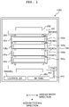
- Ahead system 100 and a printer (a printing device) 1000 being one embodiment of the present invention will be described with reference to FIGS. 1 to 23 .
- the printer 1000 mainly comprises four of the head systems 100, a platen 200, a pair of conveying rollers 301, 302 as a conveying device, an ink tank 400, a reservoir 500, a controller (control unit) 600, and a casing (housing) 700 that houses these.
- a direction that the pair of conveying rollers 301, 302 are aligned that is, a direction that a medium PM is conveyed during image formation will be called a "medium feeding direction”.
- a direction extending in a horizontal plane and orthogonal to the medium feeding direction will be called a "medium width direction”.
- Each of the four head systems 100 is a so-called line type head (a head bar), and is supported at both end portions thereof in the medium width direction by a frame 100a.
- the frame 100a supports each of the four head systems 100 so that the medium feeding direction (a conveying direction) of the printer 1000 matches with a front-rear direction (mentioned later) of each of the four head systems 100, and nozzle surfaces 40n (mentioned later) of the four head systems 100 face an upper surface of the platen 200.
- the frame 100a is provided to each of the head systems 100.
- the four head systems 100 may be collectively supported by a single frame 100a.
- each of the four head systems 100 is configured to discharge two kinds out of four mutually differing kinds of inks.
- These four kinds of inks are, for example, cyan ink, magenta ink, yellow ink, and black ink.
- the ink may be an ultraviolet curing type ink (a UV ink). Specific structure and function of the head system 100 will be mentioned later.
- the platen 200 is a plate-like member that supports the medium PM from an opposite side to the head system 100 (from below), when ink is discharged toward the medium PM from the head system 100. Hence, the upper surface of the platen 200 corresponds to a conveying surface of the medium PM.
- the pair of conveying rollers 301, 302 are disposed (arranged) sandwiching the platen 200 in the medium feeding direction.
- the pair of conveying rollers 301, 302 function as the conveying device that feeds the medium PM in the medium feeding direction in a certain form, when an image is formed on the medium PM by the head system 100.
- the ink tank 400 is divided into four to enable it to house the four colors of inks.
- the four colors of inks are fed to the reservoir 500 by a duct 410.
- the reservoir 500 too is divided into four to enable it to house the four colors of inks.
- Each color of ink that has been fed to the reservoir 500 is circulated between the reservoir 500 and the head system 100 via an unillustrated duct and unillustrated pump.
- the controller 600 carries out overall control of each of portions configuring the printer 1000 to cause each of the portions to perform image formation on the medium PM, and so on.
- the controller 600 comprises an FPGA (Field Programmable Gate Array), an EEPROM (Electrically Erasable Programmable Read-Only Memory), a RAM (Random Access Memory), and so on.
- the controller 600 may comprise the likes of a CPU (Central Processing Unit) or an ASIC (Application Specific Integrated Circuit).
- the controller 600 is data-communication-capably connected to an external device such as a PC (not illustrated), and controls each of the portions of the printer 1000 based on printing data sent from said external device.
- a liquid discharging device (liquid discharge device) 900 of the present embodiment comprises the controller 600 and at least one head system 100.
- each of the four head systems 100 mainly comprises a casing (housing) 10, and, housed in the casing 10, two preheating channels 20, a sub-tank 30, ten head mechanisms 40, ten sets of ink tube sets ITS linking the sub-tank 30 and the ten head mechanisms 40, a coolant circulation mechanism 50, a relay board 70, and a control board unit 80. Since the four head systems have the same configuration as each other, hereafter, description will be made focusing on one of the four.
- a direction that the ten head mechanisms 40 are aligned staggered (in a zigzag manner) will be called a width direction of the head system 100 (a first direction), and a direction that the ten head mechanisms 40 and the sub-tank 30 are aligned will be called an up-down direction.
- a direction orthogonal to the width direction and the up-down direction will be called the front-rear direction of the head system 100 (a second direction).
- a near side and far side of a paper surface of FIG. 2 will be assumed to be a front side and rear side in the front-rear direction.
- a left side and right side when looking from the front side in the front-rear direction will be assumed to be a left side and right side in the width direction.
- a side that the sub-tank 30 is positioned with respect to the ten head mechanisms 40 will be assumed to be an upper side, and an opposite side thereto will be assumed to be a lower side.
- the width direction of the head system 100 corresponds to (matches with) the medium width direction of the printer 1000
- the front-rear direction of the head system 100 corresponds to (matches with) the medium feeding direction of the printer 1000.
- the casing 10 may be formed by a metal, for example.
- the casing 10 includes: a first portion 11; and a second portion 12 attachable/detachable to/from the first portion 11.
- the first portion 11 has a top plate 11a and bottom portion 11b, a front wall 11c ( FIG. 18 ; illustration of the front wall 11c is omitted in FIG. 2 to render visible inside the first portion 11), a rear wall 11d, a left wall (side wall) 11e, and a right wall 11f.
- the top plate 11a and bottom portion 11b have a rectangular shape long in the width direction in planar view.
- the top plate 11a which has a step portion ST 11 , has its left end vicinity positioned above another region (a region rightward of the left end vicinity) thereof.
- the front wall 11c and rear wall 11d are each a flat plate extending along a plane including the width direction and the up-down direction
- the left wall 11e and right wall 11f are each a flat plate extending along a plane including the front-rear direction and the up-down direction.
- the left wall 11e and right wall 11f are orthogonal to the front wall 11c (a rear surface of the front wall 11c) and rear wall 11d (a front surface of the rear wall 11d).
- an upper portion of the left wall 11e is provided with an electrical connector CN, and below the electrical connector CN, there are provided four air flow ports AP 10 .
- Below the four air flow ports AP 10 there are provided two ink supply ports ISP 10 and two ink discharge ports IDP 10 , and below these, there are provided a coolant supply port CSP 10 and a coolant discharge port CDP 10 .
- FIG. 2 illustration of the electrical connector CN, the air flow ports AP 10 , and each of the supply ports and discharge ports is omitted.
- an electrical short circuit can be prevented from occurring in the electrical connector CN, even when ink or coolant (for example, water) has leaked from each of the supply ports or each of the discharge ports.
- ink or coolant for example, water
- an insulative ink such as UV ink, for example, is employed as the ink
- a risk of electrical short circuit occurrence in the case of it having leaked is smaller than in the case of water leakage.
- the coolant supply port CSP 10 and the coolant discharge port CDP 10 being disposed below the ink supply ports ISP 10 and the ink discharge ports IDP 10 , the risk of electrical short circuit occurrence is further reduced.
- the second portion 12 has a top plate 12a, a bottom plate 12b, a front wall 12c, a rear wall 12d, a left wall 12e, and a right wall 12f.
- the bottom plate 12b of the second portion 12 abuts on a right end vicinity of the top plate 11a of the first portion 11.
- the preheating channel 20 feeds to the sub-tank 30 ink that has been supplied to the head system 100 via the ink supply port ISP 10 of the casing 10, and, at the same time, raises the temperature of the ink.
- two of the preheating channels 20 are disposed aligned in the front-rear direction in a vicinity of the bottom portion 11b of the first portion 11 of the casing 10.
- Each of the two preheating channels 20 has a long shape, and has its longitudinal direction disposed matching with the width direction of the head system 100.
- the preheating channel 20 is positioned on a downstream side of the ink supply port ISP 10 and an upstream side of the sub-tank 30 in a flow direction of the ink. Note that the preheating channel 20 of FIG. 2 is depicted by dotted lines, in order to allow visual observation of a structure positioned on its far side.
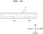
- each of the two preheating channels 20 has: a channel block 21; a heater module 22 thermally connected to the channel block 21; and a radiation sheet 23 affixed to the channel block 21.
- the channel block 21 passes ink along a channel defined (demarcated) on its inside, and, while doing so, applies heat from the heater module 22 to the ink.
- the channel block 21 is preferably formed by a material having a high heat transfer coefficient, and may be formed by a metal such as aluminum, for example.
- the channel block 21 has: a main body portion 211; and heater support pieces 212, 213 formed integrally with the main body portion 211.
- the main body portion 211 is rectangular bar shaped, and extends along the width direction of the head system 100.
- the main body portion 211 has a front surface 211c and a rear surface 211d that extend along a plane orthogonal to the front-rear direction of the head system 100.
- an ink channel IC 20 is defined inside the main body portion 211.
- the ink channel IC 20 includes: a linear first portion A1 extending in a longitudinal direction of the main body portion 211 (that is, the left-right direction) in a plane including the left-right direction and the front-rear direction; a linear second portion A2 positioned above the first portion A1 and extending parallel to the first portion A1; and a U-shaped turnback portion A3 linking a right end A1f of the first portion A1 and a right end A2f of the second portion A2.
- a left end A1e of the first portion A1 is an upstream end ICa 20 of the ink channel IC 20 .
- the right end A1f of the first portion A1 is connected to a lower end A3b of the turnback portion A3.
- a left end A2e of the second portion A2 is a downstream end ICb 20 of the ink channel IC 20 .
- the right end A2f of the second portion A2 is connected to an upper end A3a of the turnback portion A3.
- a cross-sectional shape of the ink channel IC 20 is an ellipse or oval.
- a long axis of the ellipse corresponds to (matches with) the up-down direction, and a short axis of the ellipse corresponds to (matches with) the front-rear direction.
- the cross-sectional shape of the ink channel IC 20 is configured as an ellipse, it is easier for a contact area between the ink flowing along the ink channel IC 20 and the main body portion 211 to be made large, compared to when the cross-sectional shape is a perfect circle.
- heat from the heater module 22 can be efficiently applied to the ink, and a generated heat amount of the heater module 22 required for warming the ink can be reduced.
- excessive temperature rise of the heater module 22 can be suppressed, and, consequently, excessive temperature rise in the casing 10 can be suppressed.
- a channel length of the ink channel IC 20 that is, a channel length between the upstream end ICa 20 and the downstream end ICb 20 is about 600 mm to 900 mm, for example.
- a cross-sectional area of the ink channel IC 20 (an area of a cross section in a plane orthogonal to a direction that the channel extends) is about 5 mm 2 to 15 mm 2 , for example.
- These channel length and cross-sectional area which are a channel length and cross-sectional area of the channel defined within the channel block 21, are a channel length and cross-sectional area of a region where warming of ink by the heater module 22 is performed.
- the channel length of the ink channel IC 20 is larger than a dimension in the left-right direction of first through fourth reservoir portions R1-R4 (mentioned later) of the sub-tank 30. Moreover, the cross-sectional area of the ink channel IC 20 is smaller than an area of a cross section in a plane orthogonal to the left-right direction of each of the first through fourth reservoir portions R1-R4 of the sub-tank 30.
- the heater support piece 212 is an angular portion projecting forwards and bending downwards from an upper edge of the front surface 211c of the main body portion 211, and has a surface 212s facing the front surface 211c ( FIG. 4B ).
- the heater support piece 213 is an angular portion projecting forwards and bending upwards from a lower edge of the front surface 211c of the main body portion 211, and has a surface 213s facing the front surface 211c.
- a slit SL 21 casing the heater module 22 is defined by the front surface 211c and the heater support pieces 212, 213.
- the heater module 22 generates heat for applying to the channel block 21.
- the heater module 22 has: a heater 221; a heat-dissipating (heat-radiating, heat-releasing) sheet 222; and a metal plate 223.
- the heater 221 is a long planar (belt-like) heater.
- the heater 221 has: a long heat-generating surface 221m; and an opposite surface 221n on an opposite side to the heat-generating surface 221m.
- the heat-dissipating sheet 222 releases to outside of the preheating channel 20 excess heat generated by the heater 221.
- the heat-dissipating sheet 222 may be configured as a long planar (belt-like) member formed by an elastic material having a high heat transfer coefficient, such as silicone, for example.
- the heat-dissipating sheet 222 is bonded to the heater 221 with its longitudinal direction matched with a longitudinal direction of the heater 221. Specifically, one surface of the heat-dissipating sheet 222 is bonded to the opposite surface 221n of the heater 221.
- the metal plate 223 releases to outside of the preheating channel 20 excess heat transmitted to the heat-dissipating sheet 222 from the heater 221.
- the metal plate 223 may be configured as a long flat plate formed by a material having a high heat transfer coefficient, for example, aluminum.
- the metal plate 223 is bonded to the heat-dissipating sheet 222 with its longitudinal direction matched with a longitudinal direction of the heat-dissipating sheet 222. Specifically, one surface of the metal plate 223 is bonded to an entire region of a surface on an opposite side to a surface bonded to the heater 221 of the heat-dissipating sheet 222.
- the heater module 22 is inserted into the slit SL 21 to be disposed therein.
- the heat-dissipating sheet 222 is compressed in a thickness direction, whereby the heater 221 and the metal plate 223 are respectively pressed rearwards and frontwards.
- the heat-generating surface 221m of the heater 221 is closely or tightly in contact with the front surface 211c of the main body portion 211
- the metal plate 223 is closely or tightly in contact with the surfaces 212s, 213s of the heater support pieces 212, 213.
- the radiation sheet 23 is provided for efficiently radiating heat of the channel block 21 to outside. As depicted in FIG. 4D , the radiation sheet 23 is affixed (attached) to the rear surface 211d in a region excluding a lower edge vicinity and both end portion vicinities in a longitudinal direction of the rear surface 211d of the main body portion 211 of the channel block 21.
- the radiation sheet 23 may be configured as a sheet formed by a material having a higher radiation rate than the channel block 21, for example, a carbon sheet, heat radiating silicone, or the like.
- a temperature measuring device TM 20 is affixed to a vicinity of a left lower end of the rear surface 211d, that is, a vicinity of the upstream end ICa 20 of the ink channel IC 20 .
- the temperature measuring device TM 20 is a thermistor, for example.
- the temperature measuring device TM 20 measures a temperature of ink flowing into the ink channel IC 20 .
- the temperature of ink that has been measured by the temperature measuring device TM 20 is sent to the controller 600 via the relay board 70 (mentioned later).
- the sub-tank 30 receives the ink that has had its temperature raised in the preheating channel 20, and stores the ink. In addition, the sub-tank 30 performs temperature raising of the stored ink too.
- the ink stored in the sub-tank 30 is distributed to each of the plurality of head mechanisms 40.
- the sub-tank 30 is disposed above the two preheating channels 20.
- the sub-tank 30, which has a long shape, is disposed so that its longitudinal direction coincides with the width direction of the head system 10.
- the sub-tank 30 is positioned on a downstream side of the preheating channels 20 and an upstream side of the plurality of head mechanisms 40 in the flow direction of the ink.
- the sub-tank 30 is configured by: a main body portion 31; a top plate 32; and a bottom plate 33.
- a sub-tank heater 34 ( FIG. 6 ) is affixed (attached) to a lower surface of the bottom plate 33.
- the main body portion 31 is formed by a resin such as a POM, for example. Thermal conductivity of these resins is about 0.1 to 0.5 W/m ⁇ K.
- the main body portion 31 has: a front wall 31c and rear wall 31d that extend along a plane orthogonal to the front-rear direction of the head system 100; and a left wall 31e and right wall 31f that extend along a plane orthogonal to the width direction of the head system 100.
- the left wall 31e and right wall 31f each have a step portion ST 31 in their center portion in the front-rear direction. Moreover, front-side portions 31ec, 31fc positioned on front sides of the step portions ST 31 in the left wall 31e and right wall 31f are positioned leftward of rear-side portions 31ed, 31fd positioned on rear sides of the step portions ST 31 in the left wall 31e and right wall 31f.
- the front-side portion 31ec has an ink supply port ISP 30 provided forwardly in its lower edge vicinity, and has an ink discharge port IDP 30 provided rearwardly in its lower edge vicinity. Moreover, the front-side portion 31ec has two air flow ports AP 30 provided aligned to front and rear in its upper edge vicinity.
- the rear-side portion 31ed has an ink supply port ISP 30 provided rearwardly in its lower edge vicinity, and has an ink discharge port IDP 30 provided forwardly in its lower edge vicinity.
- the rear-side portion 31ed has two air flow ports AP 30 provided aligned to front and rear in its upper edge vicinity.
- the main body portion 31 further has a first separating wall 31w1, a second separating wall 31w2, and a third separating wall 31w3 that are parallel to the front wall 31c and rear wall 31d and extend over a space between the left wall 31e and right wall 31f.
- the first separating wall 31w1 is provided in the same position as the step portions ST 31 of the left wall 31e and right wall 31f in the front-rear direction.
- the second separating wall 31w2 is provided between the ink supply port ISP 30 and ink discharge port IDP 30 and between the two air flow ports AP 30 in the front-side portion 31ec of the left wall 31e in the front-rear direction.
- the third separating wall 31w3 is provided between the ink supply port ISP 30 and ink discharge port IDP 30 and between the two air flow ports AP 30 in the rear-side portion 31ed of the left wall 31e in the front-rear direction.
- the top plate 32 is a flat plate formed by a metal, for example.
- a planar view shape of the top plate 32 is the same as a shape of outline of the main body portion 31 viewed from above.
- the top plate 32 is fixed to an upper end portion of the main body portion 31 with unillustrated sealing rubber sandwiched therebetween.
- the bottom plate 33 is a flat plate formed by a metal (for example, aluminum, copper, stainless steel, or the like). Thermal conductivities of these metals, being at a level of approximately 20 to 400 W/m ⁇ K, are larger than the thermal conductivity of the resin forming the main body portion 31.
- a planar view shape of the bottom plate 33 is the same as the shape of outline of the main body portion 31 viewed from above.
- a lower surface of the bottom plate 33 is provided with ten (ten sets of) ink flow port sets S.
- Each of the ink flow port sets S includes a first ink supply port SP1, a second ink supply port SP2, a first ink discharge port DP1, and a second ink discharge port DP2.
- the ten ink flow port sets S are disposed staggered (in a zigzag manner) along the width direction of the head system 100. Moreover, in each ink flow port set S, the first ink supply port SP1, the second ink supply port SP2, the first ink discharge port DP1, and the second ink discharge port DP2 are disposed staggered (in a zigzag manner) along the width direction.
- the bottom plate 33 is fixed to a lower end portion of the main body portion 31 with unillustrated sealing rubber sandwiched therebetween.
- an inside of the sub-tank 30 has defined therein, in order from its front side, the first reservoir portion R1, the second reservoir portion R2, the third reservoir portion R3, and the fourth reservoir portion R4.
- a dimension in a longitudinal direction of each of the first through fourth reservoir portions R1-R4, that is, a dimension between the left wall 31e and right wall 31f is about 300 mm to 500 mm, for example.
- a cross-sectional area of each of the first through fourth reservoir portions R1-R4 is about 1000 mm 2 to 1500 mm 2 , for example.
- FIG. 7 depicts how the first reservoir portion R1, the second reservoir portion R2, the third reservoir portion R3, and the fourth reservoir portion R4 are connected to the ink flow port sets S. Since FIG. 7 is an upper surface view and FIG. 6 is a bottom surface view, disposition of the ten ink flow port sets S and disposition of each of the supply ports and discharge ports in the two drawings are upwardly/downwardly inverted on paper surfaces of the drawings.
- the first reservoir portion R1 communicates with the first ink supply port SP1 of each ink flow port set S (the supply port positioned on a right front side in each set).
- the second reservoir portion R2 communicates with the first ink discharge port DP1 of each ink flow port set S (the discharge port positioned on a left front side in each set).
- the third reservoir portion R3 communicates with the second ink discharge port DP2 of each ink flow port set S (the discharge port positioned on a right rear side in each set).
- the fourth reservoir portion R4 communicates with the second ink supply port SP2 of each ink flow port set S (the supply port positioned on a left rear side in each set).
- the distribution channels DC which are defined by three-dimensional structures formed integrally with each wall of the main body portion 31, include a tunnel-like channel DC1 linking the first reservoir portion R1 and the first ink supply port SP1, a tunnel-like channel DC2 linking the second reservoir portion R2 and the first ink discharge port DP1, a tunnel-like channel DC3 linking the third reservoir portion R3 and the second ink discharge port DP2, and a tunnel-like channel DC4 linking the fourth reservoir portion R4 and the second ink supply port SP2.
- FIG. 8 depicts only a vicinity of the left wall 31e of the main body portion 31.
- Disposition of the channels DC1-DC4 is not limited to the disposition depicted in FIG. 8 , and there may be configured any mode in which channels leading from bottom portions of each of the first through fourth reservoir portions R1-R4 to corresponding supply ports or discharge ports are provided so as not to interfere with each other.
- the distribution channels DC may be formed inside a channel member of a separate body from the main body portion 31.
- the sub-tank heater 34 applies heat to the ink stored in the first through fourth reservoir portions R1-R4.
- the sub-tank heater 34 which is a planar heater similar to the heater 221 of the preheating channel 20, is provided on a bottom surface of the bottom plate 33 ( FIG. 6 ).
- the sub-tank heater 34 is attached or affixed to the bottom surface of the bottom plate 33 so as to be positioned between the ink flow port sets S in the front-rear direction and width direction of the head system 100. Heat generated by the sub-tank heater 34 is applied to the ink in the distribution channels DC and in the first through fourth reservoir portions R1-R4 via the bottom plate 33 which is a metal plate.
- Ink that has been warmed in bottom portions of the first through fourth reservoir portions R1-R4 moves to upper portions of the first through fourth reservoir portions R1-R4 due to temperature rise.
- a convection current of ink occurs inside each of the first through fourth reservoir portions R1-R4, and the ink inside the first through fourth reservoir portions R1-R4 is therefore efficiently heated.
- the four air flow ports AP 30 of the left wall 31e are respectively connected to the four air flow ports AP 10 of the casing 10 by unillustrated ducts.
- An inside of each of the first through fourth reservoir portions R1-R4 is divided into a liquid phase where the ink is stored and a gaseous phase, above the liquid phase, where air is present.
- the first, third, and fifth from left ink flow port sets S, of the five ink flow port sets S aligned on the rear side in the front-rear direction of the head system 100 have temperature measuring devices TM 30 provided one each in their vicinities.
- the temperature measuring device TM 30 is a thermistor, for example.
- the temperature measuring device TM 30 measures a temperature of ink flowing out from the sub-tank 30.
- the temperature of ink that has been measured by the temperature measuring device TM 30 is sent to the controller 600 via the relay board 70 (mentioned later).
- the head mechanism 40 discharges toward the medium PM ink that has been supplied from the sub-tank 30. In addition, the head mechanism 40 performs temperature raising of the ink flowing along inside the head mechanism 40, too.
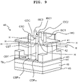
- each of the ten head mechanisms 40 has, in order from above, a connection plate 41, a pair of channel blocks 42, an alignment frame 43, a cooling frame 44, a front-end frame 45, and a head 46.
- an inside of the front-end frame 45 is provided with a head heater mechanism 47 and a discharge controller 48.
- the head mechanism 40 further has a wiring connection portion WC extending in the up-down direction over a space between upwards of the connection plate 41 and the front-end frame 45, as depicted in FIG. 14 .
- connection plate 41 is a plate-like member for connecting the head mechanism 40 and each of ducts (conduits) connected to the head mechanism 40.
- the connection plate 41 is provided with six holes H that penetrate the connection plate 41 in a thickness direction.
- connection plate 41 The six holes H of the connection plate 41 are respectively inserted with a first ink supply tube connecting portion ISC1, a second ink supply tube connecting portion ISC2, a first ink discharge tube connecting portion IDC1, a second ink discharge tube connecting portion IDC2, a coolant supply tube connecting portion CSC, and a coolant discharge tube connecting portion CDC.
- Each of the connecting portions ISC1, ISC2, IDC1, IDC2, CSC, and CDC is a cylindrical member.
- a lower end portion of each connecting portion is provided with an O-ring (not illustrated) surrounding said lower end portion.
- Each connecting portion is inserted in the hole H with the O-ring positioned in the hole H, and thereby projects to an upper surface side of the connection plate 41. In this state, each connecting portion extends in the up-down direction orthogonally to the connection plate 41.
- each connecting portion is configured to be connected with a one-touch joint (a joint configured so that connection and fixing of a tubular member and the joint is completed merely by the tubular member being inserted in the joint). That is, each connecting portion is a one-touch joint-dedicated tubular member to be connected with a one-touch joint.
- the upper end portions of the first and second ink supply tube connecting portions ISC1, ISC2, the first and second ink discharge tube connecting portions IDC1, IDC2, the coolant supply tube connecting portion CSC, and the coolant discharge tube connecting portion CDC are in the same position in the up-down direction. That is, upper end surfaces of the first and second ink supply tube connecting portions ISC1, ISC2, the first and second ink discharge tube connecting portions IDC1, IDC2, the coolant supply tube connecting portion CSC, and the coolant discharge tube connecting portion CDC are flush with each other.
- the upper end portions of each of the connecting portions being positioned at the same height, work to connect each of ink tubes to each of the connecting portions can be made easy.
- the pair of channel blocks 42 define on a lower side of the connection plate 41 a channel that supplies to the head 46 ink that has been supplied from the sub-tank 30 and a channel that discharges to the sub-tank 30 ink that has not been discharged (ejected) by the head 46.
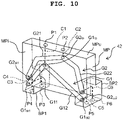
- Each of the pair of channel blocks 42 is formed by a resin such as POM, for example, and, as depicted in FIG. 10 , has: a rectangular plate-like main portion MP; and a first base portion BP1 and second base portion BP2 that project from the main portion MP
- An upper surface MPu of the main portion MP has formed therein flow ports PI, P2 aligned in a long side direction of the main portion MP.
- a lower surface of the first base portion BP1 has formed therein flow ports P3, P4 aligned in a thickness direction of the main portion MP, and a lower surface of the second base portion BP2 has formed therein flow ports P5, P6 aligned in the thickness direction of the main portion MP.
- a surface MPi of the main portion MP has formed therein: a first concave groove G1; and a second concave groove G2.
- the first concave groove G1 includes: a first portion G11 extending obliquely downwardly toward the first base portion BP1 from a top G1 tp to a lower end portion G1 bt1 ; and a second portion G12 extending obliquely downwardly toward the second base portion BP2 from the top G1 tp to a lower end portion G1 bt2 .
- the second concave groove G2 includes: a first portion G21 extending obliquely downwardly toward the first base portion BP1 from a top G2 tp to a lower end portion G2 bt1 ; and a second portion G22 extending obliquely downwardly toward the second base portion BP2 from the top G2 tp to a lower end portion G2 bt2 .
- An inside of the main portion MP is provided with a channel C1 linking the flow port P1 and the first concave groove G1, a channel C2 linking the flow port P2 and the second concave groove G2, a channel C3 linking the flow port P3 and the first concave groove G1, a channel C4 linking the flow port P4 and the second concave groove G2, a channel C5 linking the flow port P5 and the first concave groove G1, and a channel C6 linking the flow port P6 and the second concave groove G2.
- the pair of channel blocks 42 are joined sandwiching an elastic sheet (unillustrated), in such a manner that surfaces MPi of the pair of channel blocks 42 face each other.
- a joined body of the pair of channel blocks 42 is fixed to a lower surface of the connection plate 41 via unillustrated sealing rubber.
- the flow ports PI, P2 of the channel block 42 on the far side of the paper surface of FIG. 9 respectively communicate with the second ink supply tube connecting portion ISC2 and second ink discharge tube connecting portion IDC2 via the holes H of the connection plate 41
- the flow ports PI, P2 of the channel block 42 positioned on the near side of the paper surface of FIG. 9 respectively communicate with the first ink supply tube connecting portion ISC1 and first ink discharge tube connecting portion IDC1 via the holes H of the connection plate 41.
- the alignment frame 43 is a flat plate member made of SUS, for example.
- the alignment frame 43 has: a center through-hole TH 43 rectangular in planar view vertically penetrating a center portion of the alignment frame 43; and eight ink channels IC 43 circular in planar view provided in a periphery of the center through-hole TH 43 .
- the alignment frame 43 is fixed to lower surfaces of the pair of channel blocks 42. In this state, the flow ports P3-P6 on the lower surfaces of the pair of channel blocks 42 communicate with the ink channels IC 43 of the alignment frame 43.
- the cooling frame 44 is a thick plate-like member rectangular in planar view, as depicted in FIG. 11 .
- the cooling member 44 may be formed by a material having high thermal conductivity, such as aluminum, for example.
- a coolant channel CC substantially U-shaped in planar view is formed inside the cooling frame 44.
- the coolant channel CC extends substantially in a U-shaped manner in planar view between a coolant supply port CSP 44 and a coolant discharge port CDP 44 in an upper surface of the cooling frame 44.
- a periphery of the coolant channel CC there are provided: eight ink channels IC 44 circular in planar view; and a center through-hole TH 44 .
- the cooling frame 44 is fixed to a lower surface of the alignment frame 43. In this state, each of the eight ink channels IC 43 of the alignment frame 43 communicate with each of the eight ink channels IC 44 of the cooling frame 44.
- a coolant supply tube CST and a coolant discharge tube CDT are provided between the connection plate 41 and the cooling frame 44.
- An upper end of the coolant supply tube CST is provided with an O-ring (unillustrated).
- the coolant supply tube CST is connected to the connection plate 41 by having its upper end, along with the O-ring, inserted from a lower side into the hole H connected with the coolant supply tube connecting portion CSC of the connection plate 41.
- a lower end portion of the coolant supply tube CST is connected to the coolant supply port CSP 44 of the cooling frame 44 via the center through-hole TH 43 of the alignment frame 43.
- An upper end of the coolant discharge tube CDT is provided with an O-ring (unillustrated).
- the coolant discharge tube CDT is connected to the connection plate 41 by having its upper end, along with the O-ring, inserted from a lower side into the hole H connected with the coolant discharge tube connecting portion CDC of the connection plate 41.
- a lower end portion of the coolant discharge tube CDT is connected to the coolant discharge port CDP 44 of the cooling frame 44 via the center through-hole TH 43 of the alignment frame 43.
- the front-end frame 45 is a flat plate member made of SUS, for example.
- the front-end frame 45 has: a center through-hole TH 45 rectangular in planar view vertically penetrating a center portion of the front-end frame 45; and eight ink channels IC 45 rectangular in planar view provided in a periphery of the center through-hole TH 45 .
- the front-end frame 45 is fixed to a lower surface of the cooling frame 44. In this state, each of the eight ink channels IC 45 communicate with each of the eight ink channels IC 44 of the cooling frame 44.
- the head 46 comprises: a channel unit 461; and a piezoelectric actuator 462 ( FIGS. 11 and 12 ).
- the channel unit 461 is a laminated structure having laminated therein, in order from above, an ink sealing film 461A, plates 461B-461E, and a nozzle plate 461F. As depicted in FIG. 12 , a channel CH is formed inside the channel unit 461.
- the channel CH includes: eight ink flow ports IP 46 ; four manifold channels M1, M2, M3, M4; and forty-eight individual channels iCH.
- Each of the four manifold channels M1-M4 is a linear channel, and communicates at both ends thereof with the ink flow ports IP 46 .
- Each of the four manifold channels M1-M4 is connected with twelve individual channels iCH.
- each of the individual channels iCH includes a pressure chamber 1, a descender channel 2, and a nozzle 3.
- An upper surface of the pressure chamber 1 is formed by the ink sealing film 461A.
- the descender channel 2 extends in the up-down direction from the pressure chamber 1 to the nozzle 3.
- the nozzle 3, which is a minute opening discharging ink toward the medium PM, is formed in the nozzle plate 461F.
- a nozzle line (nozzle array) L 3 ( FIG. 12 ) is formed in the nozzle surface 40n along a direction that the manifold channels M1-M4 extend.
- the piezoelectric actuator 462 is configured by: a first piezoelectric layer L1 provided on an upper surface of the channel unit 461; a second piezoelectric layer L2 above the first piezoelectric layer L1; a common electrode cET sandwiched by the first piezoelectric layer L1 and second piezoelectric layer L2; and a plurality of individual electrodes iET provided on an upper surface of the second piezoelectric layer L2.
- the plurality of individual electrodes iET are provided on the upper surface of the second piezoelectric layer L2 so as to be respectively positioned above the pressure chambers 1 of the plurality of individual channels iCH.
- a portion sandwiched by the common electrode cET and each of the plurality of individual electrodes iET, of the second piezoelectric layer L2 becomes an active portion AC polarized in a thickness direction.
- the head heater mechanism 47 applies heat to the head 46 to heat the ink flowing in the head 46.
- the head heater mechanism 47 has: a heat transfer member 471; a film heater 472; and a plate spring 473.
- the heat transfer member 471 is formed by a metal of high thermal conductivity, for example, aluminum. As depicted in FIG. 11 (the portion in a box of FIG. 11 shows a lower surface perspective view of the heat transfer member 471) and FIG. 14 , the heat transfer member 471 has: a plate portion 471A substantially square in planar view; a pair of wall portions 471B projecting upwardly from both end portions of an upper surface of the plate portion 471A; and a frame-like protruding portion 471C protruding downwardly from an outer edge of a lower surface of the plate portion 471A.
- the heat transfer member 471 is fitted to an upper surface of the head 46 in such a manner that a lower end portion of the frame-like protruding portion 471C abuts on the channel unit 461 in a periphery (on an outer side) of the piezoelectric actuator 462.
- a flexible printed circuit board (FPC) 481 of the discharge controller 48 is partially sandwiched between the frame-like protruding portion 471C and the channel unit 461 (this will be mentioned later).
- the film heater 472 is substantially square in planar view.
- the film heater 472 is disposed on the heat transfer member 471 in such a manner that a heat generating surface of the film heater 472 abuts on the upper surface of the plate portion 471A of the heat transfer member 471. Heat generated by the film heater 472 is applied to the channel unit 461 via the heat transfer member 471.
- the plate spring 473 is disposed on an upper surface of the film heater 472.
- the discharge controller 48 comprises: the FPC (Flexible Printed Circuit, flexible printed circuit board) 481; and a control board 482 mounted with a driver IC. Illustration of the FPC 481 is omitted in FIG. 11 .
- the FPC 481 is belt-like, and, in its center portion 481A in a longitudinal direction, has formed a plurality of contacts (unillustrated).
- the control board 482 is disposed parallel to the plate portion 471A of the heat transfer member 471, above the plate spring 473 of the head heater mechanism 47.
- the control board 482 abuts on the cooling frame 44, while at the same time being separated from the film heater 472 by the plate spring 473. Moreover, radiant heat of the film heater 472 is blocked by the plate spring 473, and heating of the control board 482 is suppressed.
- the FPC 481 is disposed on an upper surface of the piezoelectric actuator 462 in such a manner that each of the plurality of contacts of its center portion 481A are electrically connected to each of the plurality of individual electrodes iET of the piezoelectric actuator 462.
- a portion to an outer side of the center portion 481A of the FPC 481 passes between the heat transfer member 471 of the head heater mechanism 47 and the head 46, and extends upwardly along a side surface of the heat transfer member 471 to be connected to the control board 482.
- each of the plurality of individual electrodes iET of the piezoelectric actuator 462 is connected to the control board 482 via the FPC 481.
- the head 46 is fixed to the front-end frame 45. In this state, each of the eight ink flow ports IP 46 communicate with each of the eight ink channels IC 45 of the front-end frame 45.
- the piezoelectric actuator 462, the head heater mechanism 47, and the discharge controller 48 are disposed inside the center through-hole TH 45 of the front-end frame 45.
- a temperature measuring device TM 40 in a vicinity of a region in contact with the heat transfer member 471, of an upper surface of the channel unit 461, there is provided a temperature measuring device TM 40 .
- the temperature measuring device TM 40 is a thermistor, for example. Note that illustration of the temperature measuring device TM 40 is omitted in FIG. 11 .
- the temperature measuring device TM 40 measures a temperature of ink flowing along the channel CH in the channel unit 461.
- the temperature of ink that has been measured by the temperature measuring device TM 40 is sent to the controller 600 via the relay board 70 (mentioned later).
- the wiring connection portion WC which is circuit board-like, extends vertically as depicted in FIG. 14 .
- An upper end portion of the wiring connection portion WC is disposed at a position above the connection plate 41 and adjacent to the connection plate 41.
- a lower end portion of the wiring connection portion WC is positioned inside the center through-hole TH 45 of the front-end frame 45.
- the wiring connection portion WC penetrates the center through-hole TH 43 of the alignment frame 43 and the center through-hole TH 44 of the cooling frame 44 in the up-down direction.
- An upper end of the wiring connection portion WC is connected with a flexible board 71 extending from the relay board 70 (mentioned later).
- a lower end of the wiring connection portion WC is connected with: the film heater 472 of the head heater mechanism 47; and the control board 482 of the discharge controller 48.
- Each of the head mechanisms 40 is fixed to the bottom portion 11b of the first portion 11 of the casing 10, via the alignment frame 43. In this state, the nozzle surface 40n of each head mechanism 40 is exposed toward a lower side of the casing 10. Moreover, the nozzle line L 3 of the nozzle surface 40n extends along the width direction of the head system 100.
- the bottom portion 11b of the first portion 11 of the casing 10 has the ten head mechanisms 40 disposed staggered (in a zigzag manner) therein along the width direction.
- Each of the ten head mechanisms 40 is provided in such a manner that the coolant supply tube connecting portion CSC and coolant discharge tube connecting portion CDC are positioned on its front side, and the wiring connection portion WC is positioned on its rear side.
- the remaining five head mechanisms 40 are disposed at equal intervals along the width direction of the head system 100, on a rear side of the front line FL.
- a line of head mechanisms 40 on the rear side of the front line FL will appropriately be called a rear line RL.
- Disposition of the first and second ink supply tube connecting portions ISC1, ISC2, the first and second ink discharge tube connecting portions IDC1, IDC2, the coolant supply tube connecting portion CSC, and the coolant discharge tube connecting portion CDC (appropriately collectively called a "connecting portion set") in each head mechanism 40 is as follows.
- the coolant supply tube connecting portion CSC and the coolant discharge tube connecting portion CDC are in the same position in the front-rear direction, and aligned in the width direction.
- the coolant supply tube connecting portion CSC is positioned on a left side of the coolant discharge tube connecting portion CDC.
- the first ink supply tube connecting portion ISC1 and the first ink discharge tube connecting portion IDC1 are positioned rearward of the coolant supply tube connecting portion CSC and the coolant discharge tube connecting portion CDC.
- the first ink supply tube connecting portion ISC1 and the first ink discharge tube connecting portion IDC1 are in the same position in the front-rear direction, and aligned in the width direction.
- the first ink supply tube connecting portion ISC1 is positioned on a right side of the first ink discharge tube connecting portion IDC1.
- the second ink supply tube connecting portion ISC2 and the second ink discharge tube connecting portion IDC2 are positioned rearward of the first ink supply tube connecting portion ISC1 and the first ink discharge tube connecting portion IDC1.
- the second ink supply tube connecting portion ISC2 and the second ink discharge tube connecting portion IDC2 are in the same position in the front-rear direction, and aligned in the width direction.
- the second ink supply tube connecting portion ISC2 is positioned on a left side of the second ink discharge tube connecting portion IDC2.
- the first ink discharge tube connecting portion IDC1 is positioned between the coolant supply tube connecting portion CSC and the coolant discharge tube connecting portion CDC, and the coolant discharge tube connecting portion CDC is positioned between the first ink supply tube connecting portion ISC1 and the first ink discharge tube connecting portion IDC1.
- the coolant supply tube connecting portion CSC, the first ink discharge tube connecting portion IDC1, the coolant discharge tube connecting portion CDC, and the first ink supply tube connecting portion ISC1 are aligned staggered (in a zigzag manner) in this order from left to right along the width direction of the head system 100.
- the first ink discharge tube connecting portion IDC1 is positioned between the second ink supply tube connecting portion ISC2 and the second ink discharge tube connecting portion IDC2, and the second ink discharge tube connecting portion IDC2 is positioned between the first ink supply tube connecting portion ISC1 and the first ink discharge tube connecting portion IDC1.
- the second ink supply tube connecting portion ISC2, the first ink discharge tube connecting portion IDC1, the second ink discharge tube connecting portion IDC2, and the first ink supply tube connecting portion ISC1 are aligned staggered (in a zigzag manner) in this order from left to right along the width direction of the head system 100.
- the second ink discharge tube connecting portion IDC2 is positioned between the coolant supply tube connecting portion CSC and the coolant discharge tube connecting portion CDC, and the coolant supply tube connecting portion CSC is positioned between the second ink supply tube connecting portion ISC2 and the second ink discharge tube connecting portion IDC2. That is, the second ink supply tube connecting portion ISC2, the coolant supply tube connecting portion CSC, the second ink discharge tube connecting portion IDC2, and the coolant discharge tube connecting portion CDC are aligned staggered (in a zigzag manner) in this order from left to right along the width direction of the head system 100.
- the first and second ink supply tube connecting portions ISC1, ISC2, the first and second ink discharge tube connecting portions IDC1, IDC2, the coolant supply tube connecting portion CSC, and the coolant discharge tube connecting portion CDC are in different positions from each other.
- the coolant supply tube connecting portion CSC, the first ink discharge tube connecting portion IDC1, and the second ink supply tube connecting portion ISC2 are aligned staggered (in a zigzag manner) in this order from front to rear along the front-rear direction.
- the coolant discharge tube connecting portion CDC, the first ink supply tube connecting portion ISC1, and the second ink discharge tube connecting portion IDC2 are aligned staggered (in a zigzag manner) in this order from front to rear along the front-rear direction.
- a certain connecting portion being in a different position from another connecting portion may refer to either of a state where, in the width direction, at least part of the certain connecting portion is in a different position from the other connecting portion and a state where, in the width direction, the whole of the certain connecting portion is in a different position from the other connecting portion.
- a certain connecting portion being positioned between another two connecting portions may refer to either of a state where a center portion in the width direction of the certain connecting portion is positioned between center portions in the width direction of each of the other two connecting portions and a state where an entire region in the width direction of the certain connecting portion is positioned between the other two connecting portions without overlapping either of the other two connecting portions.
- disposition of the ten head mechanisms 40 in the bottom portion 11b corresponds to disposition of the ten ink flow port sets S in the bottom plate 33 of the sub-tank 30 ( FIGS. 6 and 7 ). That is, the ten head mechanisms 40 are respectively positioned directly below the ten ink flow port sets S.
- the first ink supply port SP1 and first ink supply tube connecting portion ISC1 are in the same position as each other, the second ink supply port SP2 and second ink supply tube connecting portion ISC2 are in the same position as each other, the first ink discharge port DP1 and first ink discharge tube connecting portion IDC1 are in the same position as each other, and the second ink discharge port DP2 and second ink discharge tube connecting portion IDC2 are in the same position as each other. That is, in planar view, a center of each supply port or discharge port and a center of a channel defined within each connecting portion coincide with each other.
- each of the head mechanisms 40 is connected to the sub-tank 30 by the ink tube set ITS.
- the ink tube set ITS is illustrated by a single line in FIG. 2 , it includes four ducts (conduits, tubes, pipes), that is, a first ink supply tube IST1, a second ink supply tube IST2, a first ink discharge tube IDT1, and a second ink discharge tube IDT2 ( FIG. 19 ).
- the first ink supply tube IST1, the second ink supply tube IST2, the first ink discharge tube IDT1, and the second ink discharge tube IDT2 have the same shape as each other, and each have: a main portion MT extending linearly in the up-down direction; and a joint portion JT provided in a lower end portion of the main portion MT.
- the main portion MT is a circular tube formed by a resin or metal.
- the joint portion JT is a one-touch joint in the present embodiment.
- An outer diameter of the joint portion JT is larger than an outer diameter of the main portion MT.
- the joint portion JT is one example of a "large-diameter portion" of the present invention, and the main portion MT is one example of a "small-diameter portion" of the present invention.
- an upper end of the first ink supply tube IST1 is connected to the first ink supply port SP1, and the joint portion JT of the first ink supply tube IST1 is connected to the first ink supply tube connecting portion ISC1.
- An upper end of the second ink supply tube IST2 is connected to the second ink supply port SP2, and the joint portion JT of the second ink supply tube IST2 is connected to the second ink supply tube connecting portion ISC2.
- An upper end of the first ink discharge tube IDT1 is connected to the first ink discharge port DP1, and the joint portion JT of the first ink discharge tube IDT1 is connected to the first ink discharge tube connecting portion IDC1.
- An upper end of the second ink discharge tube IDT2 is connected to the second ink discharge port DP2, and the joint portion JT of the second ink discharge tube IDT2 is connected to the second ink discharge tube connecting portion IDC2.
- the first ink supply tube IST1, the second ink supply tube IST2, the first ink discharge tube IDT1, and the second ink discharge tube IDT2 extend linearly in the up-down direction in an entire region between the sub-tank 30 and the plurality of head mechanisms 40, below the sub-tank 30 and above the head mechanisms 40, to connect the sub-tank 30 and each of the plurality of head mechanisms 40.
- the channel block 21 of the preheating channel 20 is disposed in the vicinity of the ink tube set ITS.
- the ink tube set ITS is warmed by heat radiated from the radiation sheet 23 affixed to the channel block 21, and temperature drop of ink flowing along an inside of the ink tube set ITS is suppressed.
- the preheating channel 20 directly above said head mechanism 40 is disposed forward of the first ink supply tube IST1 and first ink discharge tube IDT1 connected to said head mechanism 40, in such a manner that the radiation sheet 23 affixed to the channel block 21 faces outer peripheral surfaces of the first ink supply tube IST1 and first ink discharge tube IDT1.
- the preheating channel 20 is disposed such that a lower end portion of the channel block 21 is positioned above upper ends of the joint portions JT of the first ink supply tube IST1 and first ink discharge tube IDT1, that is, such that an entire region of the channel block 21 in the up-down direction faces the main portions MT of the first ink supply tube IST1 and first ink discharge tube IDT1.
- the preheating channel 20 and the ink tube sets ITS can be compactly disposed in the front-rear direction, and heat radiated from the radiation sheet 23 of the preheating channel 20 can be efficiently applied to ink flowing through the ink tube sets ITS.
- the coolant circulation mechanism 50 performs supply of coolant (for example, water) to the ten head mechanisms 40 and discharge of coolant from the ten head mechanisms 40.
- coolant for example, water
- the coolant circulation mechanism 50 is disposed below the sub-tank 30 and above the plurality of head mechanisms 40 inside the first portion 11 of the casing 10.
- the coolant circulation mechanism 50 mainly comprises: two coolant supply manifolds 51 and ten coolant supply tubes 52 connected to the two coolant supply manifolds 51; and two coolant discharge manifolds 53 and ten coolant discharge tubes 54 connected to the two coolant discharge manifolds 53.
- the two coolant supply manifolds 51 are each a linear circular tube extending in the width direction of the head system 100, and each have a coolant channel defined on their inside.
- the coolant supply manifold 51 may be formed by stainless steel, for example.
- Upstream ends 51a of the two coolant supply manifolds 51 are each connected to the coolant supply port CSP 10 of the first portion 11 of the casing 10 by unillustrated ducts. A downstream end 51b of the coolant supply manifold 51 is closed.
- One of the two coolant supply manifolds 51 is positioned above the five head mechanisms 40 included in the front line FL, of the ten head mechanisms 40. More specifically, as depicted in FIG. 18 , it is positioned rearward of the ink tube sets ITS connected to the head mechanisms 40 included in the front line FL, and directly above the wiring connection portions WC of the head mechanisms 40 included in the front line FL.
- the other of the two coolant supply manifolds 51 is positioned above the head mechanisms 40 included in the rear line RL, of the ten head mechanisms 40. More specifically, as depicted in FIG. 18 , it is positioned rearward of the ink tube sets ITS connected to the head mechanisms 40 included in the rear line RL, and directly above the wiring connection portions WC of the five head mechanisms 40 included in the rear line RL.
- the coolant supply tube 52 is a duct connecting the coolant supply manifold 51 and the coolant supply tube connecting portion CSC of the head mechanism 40. Five each of the coolant supply tubes 52 are connected at equal intervals to each of the two coolant supply manifolds 51.
- each of the coolant supply tubes 52 includes: a linear portion 52A extending directly downwards from the coolant supply manifold 51; and a bending joint portion 52B linking the linear portion 52A and the coolant supply tube connecting portion CSC.
- the bending joint portion 52B extends in a front right direction in a plane orthogonal to the up-down direction from a lower end of the linear portion 52A to the coolant supply tube connecting portion CSC.
- the bending joint portion 52B includes: two angle-variable joints JT1, JT2; and a coupling tube JT3.
- the angle-variable joint JT1 includes a first portion JT11 and a second portion JT12, each having a channel defined on its inside.
- the first portion JT11 and the second portion JT12 are coupled via a pivotal axis AX1.
- the angle-variable joint JT2 includes a first portion JT21 and a second portion JT22, each having a channel defined on its inside.
- the first portion JT21 and the second portion JT22 are coupled via a pivotal axis AX2.
- the first portion JT21 is a one-touch joint.
- the coupling tube JT3 which is a circular tube having a central axis AX3, has its one end inserted in the second portion JT12 of the angle-variable joint JT1, and has its other end inserted in the second portion JT22 of the angle-variable joint JT2.
- the first portion JT11 of the angle-variable joint JT1 is fitted to the lower end of the linear portion 52A, and the first portion JT21 of the angle-variable joint JT2 is fitted to the coolant supply tube connecting portion CSC of the head mechanism 40.
- the bending joint portion 52B enables the first portion JT11 of the angle-variable joint JT1 to be pivotally moved with respect to the second portion JT12 around the pivotal axis AX1 to change an angle between an extension direction of the channel in the first portion JT11 and an extension direction of the channel in the second portion JT12, and enables the first portion JT21 of the angle-variable joint JT2 to be pivotally moved with respect to the second portion JT22 around the pivotal axis AX2 to change an angle between an extension direction of the channel in the first portion JT21 and an extension direction of the channel in the second portion JT22.
- angle-variable joints JT1, JT2 can be rotated around the central axis AX3 of the coupling tube JT3. Therefore, work to connect the linear portion 52A and the coolant supply tube connecting portion CSC can be performed easily in a limited space, while a positional relationship of the first portion JT11 and first portion JT21 is flexibly adjusted.
- the two coolant discharge manifolds 53 are each a linear circular tube extending in the width direction of the head system 100, and each have a coolant channel defined on their inside.
- a tube diameter of the coolant discharge manifold 53 may be larger than a tube diameter of the coolant supply manifold 51, and a diameter of the coolant channel define in the coolant discharge manifold 53 may be larger than a diameter of the coolant channel defined in the coolant supply manifold 51.
- the coolant discharge manifold 53 may be formed by stainless steel, for example.
- Upstream ends 53a of the two coolant discharge manifolds 53 are closed. Downstream ends 53b of the two coolant discharge manifolds 53 are each connected to the coolant discharge port CDP 10 of the first portion 11 of the casing 10 by unillustrated ducts.
- one of the two coolant discharge manifolds 53 is positioned directly above the coolant supply manifold 51 connected to the head mechanisms 40 included in the front line FL, to extend parallel to said coolant supply manifold 51.
- the other of the two coolant discharge manifolds 53 is positioned directly above the coolant supply manifold 51 connected to the head mechanisms 40 included in the rear line RL, to extend parallel to said coolant supply manifold 51.
- the coolant discharge tube 54 is a duct connecting the coolant discharge manifold 53 and the coolant discharge tube connecting portion CDC of the head mechanism 40. Five each of the coolant discharge tubes 54 are connected at equal intervals to each of the two coolant discharge manifolds 53.
- each of the coolant discharge tubes 54 includes: a linear portion 54A extending forwardly and downwardly from the coolant discharge manifold 53; and a bending joint portion 54B linking the linear portion 54A and the coolant discharge tube connecting portion CDC.
- a channel length of the coolant channel defined by the linear portion 54A is larger than a channel length of the coolant channel defined by the linear portion 52A of the coolant supply tube 52.
- a channel length of the coolant channel defined by the bending joint portion 54B is the same as a channel length of the coolant channel defined by the bending joint portion 52B of the coolant supply tube 52.
- the bending joint portion 54B extends leftwards in a plane orthogonal to the up-down direction from a lower end of the linear portion 54A to the coolant discharge tube connecting portion CDC.
- the bending joint portion 54B has the same structure as the bending joint portion 52B.
- the first portion JT11 of the angle-variable joint JT1 is fitted to a lower end of the linear portion 54A, and the first portion JT21 of the angle-variable joint JT2 is fitted to the coolant discharge tube connecting portion CDC of the head mechanism 40.
- the coolant circulation mechanism 50 and the cooling frame 44, coolant supply tube CST, and coolant discharge tube CDT of the head mechanism 40 configure the chiller (cooling mechanism) 60 that cools the control board 482 of the discharge controller 48.
- the chiller 60 cools by coolant the cooling frame 44 on which the control board 482 is abutted, and thereby cools the control board 482.
- Flow of coolant in the chiller 60 is as follows.
- Coolant that has been supplied to the coolant supply port CSP 10 of the casing 10 from a coolant tank (unillustrated) passes along the coolant supply manifold 51 and coolant supply tube 52 to be supplied to each head mechanism 40, and reaches the coolant channel CC via the coolant supply tube CST.
- Coolant that has been warmed by heat exchange with the control board 482 in the coolant channel CC passes along the coolant discharge tube CDT and coolant discharge tube 54 to reach the coolant discharge manifold 53, and passes through the coolant discharge port CDP 10 of the casing 10 to be returned to the coolant tank (unillustrated).
- the "chiller” is assumed not to include the likes of ducts or the coolant tank provided outside the head system 100.
- the relay board 70 mainly performs relay between the control board unit 80 and the discharge controller 48 of the head mechanism 40.
- the relay board 70 additionally distributes to the control board unit 80, the discharge controller 48, and each heater in the casing 10 electric power that has been supplied from the electrical connector CN of the casing 10.
- the relay board 70 is fitted, parallel to the top plate 1 1a, to a lower surface on a right end side of the top plate 11a. That is, a mounting surface (a surface of the board on which circuit elements are boarded) of the relay board 70 is parallel to upper and lower surfaces of the top plate 11a, and parallel to a plane including the width direction and the front-rear direction.
- the relay board 70 is disposed above the sub-tank 30 so as to be contained within a plane-of-projection (projection plane) in the up-down direction of the sub-tank 30 in the front-rear direction.
- a front end of the relay board 70 is positioned at the rear side of (further to the rear than) a front end of the sub-tank 30, and a rear end of the relay board 70 is positioned at the front side of (further to the front than) a rear end of the sub-tank 30.
- a region positioned above the relay board 70 of the top plate 11a is provided with a rectangular opening OP long in the width direction of the head system 100.
- the relay board 70 is connected by the flexible board 71 to each of the ten head mechanisms 40.
- the flexible board 71 is provided with the likes of a wiring linking the control board unit 80 and discharge controller 48, a wiring linking the control board unit 80 and temperature measuring device TM 40 , and a wiring supplying electric power to the head heater mechanism 47 and discharge controller 48.
- the flexible boards 71 are provided one each to each of the ten head mechanisms 40. One end of the flexible board 71 is connected to the wiring connection portion WC of the head mechanism 40, and the other end of the flexible board 71 is connected to the relay board 70.
- the flexible board 71 connected to the wiring connection portion WC of a head mechanism 40 of the front line FL extends upwardly passing between the coolant supply manifold 51 and coolant discharge manifold 53 connected to the head mechanisms 40 of the front line FL and the preheating channel 20 positioned above the head mechanisms 40 of the rear line RL.
- the flexible board 71 subsequently extends forwardly passing through a gap between the ink tube set ITS connected to the head mechanism 40 connected with said flexible board 71 and the ink tube set ITS connected to a head mechanism 40 adjacent in the width direction to said head mechanism 40, and further extends upwardly passing through a gap between the front wall 31c of the sub-tank 30 and the front wall 11c of the first portion 11 of the casing 10, to reach the relay board 70.
- the flexible board 71 may be folded in two along an extension direction between the wiring connection portion WC and the relay board 70. As a result, the flexible board 71 can be more compactly disposed, and the flexible board 71 can be disposed even if the gap between two ink tube sets ITS adjacent to each other in the width direction is small.
- the flexible board 71 connected to the wiring connection portion WC of a head mechanism 40 of the rear line RL extends upwardly passing through a gap between the coolant supply manifold 51 and coolant discharge manifold 53 connected to the head mechanisms 40 of the rear line RL and the rear wall 11d of the first portion 11 of the casing 10 and a gap between the rear wall 31d of the sub-tank 30 and the rear wall 11d, to reach the relay board 70.
- the relay board 70 being disposed above the sub-tank 30 so as to be contained within the plane-of-projection in the up-down direction of the sub-tank 30 in the front-rear direction, and by the relay board 70 and head mechanism 40 being connected by the flexible board 71 passing through the gap between the sub-tank 30 and the front wall 11c or rear wall 11d of the first portion 11, the relay board 70 and the flexible board 71 can be disposed without an accompanying increase in dimension in the front-rear direction of the casing 10.
- the relay board 70 is connected to the electrical connector CN of the left wall 11e of the first portion 11, the heater module 22 of the preheating channel 20, and the sub-tank heater 34 of the sub-tank 30, by unillustrated wirings.
- the relay board 70 is connected to the temperature measuring device TM 20 of the preheating channel 20 by an unillustrated wiring.
- the relay board 70 additionally is connected to the temperature measuring devices TM 30 of the sub-tank 30 by unillustrated wirings.
- the control board unit 80 receives a print data signal from the controller 600 of the printer 1000, and sends the print data signal to the discharge controller 48 of each head mechanism 40 via the relay board 70. Moreover, the control board unit 80 sends information, and so on, from the temperature measuring devices TM 20 , TM 30 , TM 40 received from the relay board 70 to the controller 600.
- the control board unit 80 is provided inside the second portion 12 of the casing 10 ( FIG. 2 ).
- a terminal (unillustrated) of the control board unit 80 projects downwardly, via an opening (unillustrated) provided in the bottom plate 12b of the second portion 12. Attachment/Detachment to/from the first portion 11 of the second portion 12 is performed by the terminal being attached/detached to/from a connector (unillustrated) of the relay board 70 via the opening OP provided in the top plate 1 1a of the first portion 11.
- the first ink that has flowed out from the downstream end ICb 20 of the ink channel IC 20 flows into the first reservoir portion R1 from the ink supply port ISP 30 of the sub-tank 30 via a duct.
- the first ink has its temperature raised by the sub-tank heater 34, inside the first reservoir portion R1.
- the first ink on the inside of the first reservoir portion R1 is supplied to the first ink supply port SP1 of each of the ten ink flow port sets S in the bottom portion 33, by the distribution channel DC in the lower portion of the sub-tank 30, and passes along the first ink supply tube IST1 to flow into each of the ten head mechanisms 40 from the first ink supply tube connecting portion ISC1 of each of the ten head mechanisms 40.
- the first ink flowing along the first ink supply tube IST1 has its temperature maintained or its temperature raised by heat radiated from the radiation sheet 23 of the preheating channel 20.
- the first ink that has flowed into the head mechanism 40 flows along the first and second manifolds M1, M2 inside the head mechanism 40, and is discharged onto the medium PM from the nozzles 3 of the individual channels iCH connected to these first and second manifolds M1, M2.
- the first ink flowing along the manifolds M1, M2 has its temperature raised by the head heater mechanism 47.
- the first ink that has not been discharged from the nozzles 3 flows into the first ink discharge port DP1 of the ink flow port set S, via the first ink discharge tube IDT1, from the first ink discharge tube connecting portion IDC1 of the head mechanism 40, and reaches the second reservoir portion R2 via the distribution channel DC.
- the first ink flows out from the ink discharge port IDP 30 on the front side of the sub-tank 30, reaches the ink discharge port IDP 10 of the casing 10 via a duct, and is returned to the reservoir 500.
- a channel on a downstream side of the ink supply port ISP 10 on the front side of the casing 10 and an upstream side of the ink supply port ISP 30 of the sub-tank 30 is assumed to be a front side supply channel ICsi.
- the front side supply channel ICsi is a channel leading from the ink supply port ISP 10 on the front side of the casing 10 to the ink supply port ISP 30 of the sub-tank 30 via the ink channel IC 20 in the preheating channel 20 on the front side.
- a second ink (which may be a different kind from the first ink) that has been supplied to the ink supply port ISP 10 on the rear side, of the two ink supply ports ISP 10 of the casing 10, from the reservoir 500, flows into the upstream end ICa 20 of the ink channel IC 20 of the preheating channel 20 on the rear side via a duct, and, after having had its temperature raised in the ink channel IC 20 , flows out from the downstream end ICb 20 of the ink channel IC 20 .
- the second ink that has flowed out from the downstream end ICb 20 of the ink channel IC 20 flows into the fourth reservoir portion R4 from the ink supply port ISP 30 of the sub-tank 30 via a duct.
- the second ink has its temperature raised by the sub-tank heater 34, inside the fourth reservoir portion R4.
- the second ink on the inside of the fourth reservoir portion R4 is supplied to the second ink supply port SP2 of each of the ten ink flow port sets S in the bottom portion 33, by the distribution channel DC in the lower portion of the sub-tank 30, and passes along the second ink supply tube IST2 to flow into each of the ten head mechanisms 40 from the second ink supply tube connecting portion ISC2 of each of the ten head mechanisms 40.
- the second ink flowing along the second ink supply tube IST2 has its temperature maintained or its temperature raised by heat radiated from the radiation sheet 23 of the preheating channel 20.
- the second ink that has flowed into the head mechanism 40 flows along the third and fourth manifolds M3, M4 inside the head mechanism 40, and is discharged onto the medium PM from the nozzles 3 of the individual channels iCH connected to these third and fourth manifolds M3, M4.
- the second ink flowing along the manifolds M3, M4 has its temperature raised by the head heater mechanism 47.
- the second ink that has not been discharged from the nozzles 3 flows into the second ink discharge port DP2 of the ink flow port set S, via the second ink discharge tube IDT2, from the second ink discharge tube connecting portion IDC2 of the head mechanism 40, and reaches the third reservoir portion R3 via the distribution channel DC.
- the second ink flows out from the ink discharge port IDP 30 of the sub-tank 30, reaches the ink discharge port IDP 10 of the casing 10 via a duct, and is returned to the reservoir 500.
- a channel on a downstream side of the ink supply port ISP 10 on the rear side of the casing 10 and an upstream side of the ink supply port ISP 30 of the sub-tank 30 is assumed to be a rear side supply channel IC S2 .
- the rear side supply channel IC S2 is a channel leading from the ink supply port ISP 10 on the rear side of the casing 10 to the ink supply port ISP 30 of the sub-tank 30 via the ink channel IC 20 in the preheating channel 20 on the rear side.
- each structure provided in a space between the sub-tank 30 and the head mechanism(s) 40 will be described, mainly with reference to FIGS. 2 , 18 , and 19 .
- the dispositions, positional relationships, and so on, of each of the structures described below are those of the present embodiment, and that the present invention is not limited to the forms described below.
- a center position in the front-rear direction of the first portion 11 of the casing 10, that is, a center position in the front-rear direction of a space between the front wall 11c and the rear wall 1Id is assumed to be a center portion 11C (depicted by a one dot chain line in FIG. 18 ). If a distance between an inner surface (rear surface) of the front wall 11c and an inner surface (front surface) of the rear wall 11d is assumed to be D, then a distance along the front-rear direction between the inner surface of the front wall 11c and center portion 11C and a distance along the front-rear direction between the inner surface of the rear wall 11d and center portion 11C will both be D/2. D may be set to about 80 mm to 100 mm, for example.
- the sub-tank 30 is disposed such that a center in the front-rear direction of the casing 10 is positioned on the center portion 11C.
- a dimension in the front-rear direction of the sub-tank 30 may be set to 75 mm to 95 mm, for example (note, smaller than D).
- a dimension of a gap defined by the front wall 31c of the sub-tank 30 and inner surface of the front wall 11c of the first portion 11 and a dimension of a gap defined by the rear wall 31d of the sub-tank 30 and inner surface of the rear wall 11d of the first portion 11 are equal to each other, and may each be set to about 1 mm to 5 mm, for example.
- the two preheating channels 20 extending in the width direction; the ten sets of ink tube sets ITS (that is, the ten sets of ink supply tubes IST1, IST2 and ink discharge tubes IDT1, IDT2) extending in the up-down direction and provided one each for each of the ten head mechanisms 40; the two each of the coolant supply manifolds 51 and coolant discharge manifolds 53 extending in the width direction; the ten coolant supply tubes 52 (illustration of which is omitted in FIG. 18 ); and the ten coolant discharge tubes 54 (illustration of which is omitted in FIG. 18 ).
- the two preheating channels 20, the ten sets of ink tube sets ITS, the two each of the coolant supply manifolds 51 and coolant discharge manifolds 53, and the ten each of the coolant supply tubes 52 and coolant discharge tubes 54 are disposed so as to be contained within the plane-of-projection in the up-down direction of the sub-tank 30 in the front-rear direction.
- first and second ink supply tube connecting portions ISC1, ISC2, the first and second ink discharge tube connecting portions IDC1, IDC2, the coolant supply tube connecting portion CSC, and the coolant discharge tube connecting portion CDC of each head mechanism 40 are also disposed so as to be contained within the plane-of-projection in the up-down direction of the sub-tank 30 in the front-rear direction.
- each structure being disposed so as to be contained within the plane-of-projection in the up-down direction of the sub-tank 30 means that at each position along the width direction, a front end portion at said position of each structure is positioned at the rear side of (further to the rear than) a front end portion at said position of the sub-tank 30, and a rear end portion at said position of each structure is positioned at the front side of (further to the front than) a rear end portion at said position of the sub-tank 30.
- the dotted line L 30f indicates a position of a front surface of the front wall 3 1c of the sub-tank 30 (a front end of the sub-tank 30 in the present embodiment)
- the dotted line L 30r indicates a position of a rear surface of the rear wall 31d of the sub-tank 30 (a rear end of the sub-tank 30 in the present embodiment).
- the preheating channel 20 disposed directly above the head mechanisms 40 included in the front line FL, the ink tube sets ITS connected to the head mechanisms 40 included in the front line FL, and the coolant supply manifold 51 and coolant discharge manifold 53 connected to the head mechanisms 40 included in the front line FL are contained between the inner surface (rear surface) of the front wall 11c and the center portion 11C in the front-rear direction. In other words, they are contained within a range of D/2 rearward from the inner surface of the front wall 11c.
- the preheating channel 20 disposed directly above the head mechanisms 40 included in the front line FL, the ink tube sets ITS connected to the head mechanisms 40 included in the front line FL, and the coolant supply manifold 51 and coolant discharge manifold 53 connected to the head mechanisms 40 included in the front line FL are contained between the front end of the sub-tank 30 and the center portion 11C of the first portion 11 in the front-rear direction. In other words, they are disposed so as to be contained within the plane-of-projection in the up-down direction of the sub-tank 30 in the front-rear direction, and are disposed so as to be contained in a region at the front side of (further to the front than) the center portion 11C of the first portion 11.
- the preheating channel 20 disposed directly above the head mechanisms 40 included in the rear line RL, the ink tube sets ITS connected to the head mechanisms 40 included in the rear line RL, and the coolant supply manifold 51 and coolant discharge manifold 53 connected to the head mechanisms 40 included in the rear line RL are contained between the inner surface (front surface) of the rear wall 11d and the center portion 11C in the front-rear direction. In other words, they are contained within a range of D/2 frontward from the inner surface of the rear wall 11d.
- the preheating channel 20 disposed directly above the head mechanisms 40 included in the rear line RL, the ink tube sets ITS connected to the head mechanisms 40 included in the rear line RL, and the coolant supply manifold 51 and coolant discharge manifold 53 connected to the head mechanisms 40 included in the rear line RL are contained between the rear end of the sub-tank 30 and the center portion 11C of the first portion 11 in the front-rear direction. In other words, they are disposed so as to be contained within the plane-of-projection in the up-down direction of the sub-tank 30 in the front-rear direction, and are disposed so as to be contained in a region at the rear side of (further to the rear than) the center portion 11C of the first portion 11.
- the preheating channel 20 is disposed such that a longitudinal direction of said preheating channel 20 (the channel block 21) will be parallel to a direction that the nozzle line L 3 of each head mechanism 40 extends.
- the preheating channel 20 is positioned directly above the coolant supply tube connecting portion CSC and coolant discharge tube connecting portion CDC of each head mechanism 40. That is, the preheating channel 20 is positioned above the coolant supply tube connecting portion CSC and coolant discharge tube connecting portion CDC such that at least part of the preheating channel 20 (more specifically, the channel block 21) and at least part of the coolant supply tube connecting portion CSC and coolant discharge tube connecting portion CDC overlap in the front-rear direction.
- the ink supply tubes IST1, IST2 and the ink discharge tubes IDT1, IDT2 extend in the up-down direction, that is, a direction orthogonal to the upper surface (upper surface of connecting plate 41) and nozzle surface 40n of each head mechanism 40, in an entire region between the sub-tank 30 and the head mechanism 40, at substantially a center portion in the front-rear direction of each head mechanism 40.
- the upstream end of the tube and the downstream end of the tube are disposed at the same position as each other in planar view.
- the coolant supply manifold 51 and the coolant discharge manifold 53 are disposed so as to extend parallel to a direction that the nozzle line L 3 of each head mechanism 40 extends.
- the coolant supply manifold 51 and the coolant discharge manifold 53 are positioned directly above the wiring connection portions WC of the head mechanisms 40 to which said manifolds are connected. That is, the coolant supply manifold 51 and the coolant discharge manifold 53 are positioned above the wiring connection portions WC such that at least part of the coolant supply manifold 51 and at least part of the coolant discharge manifold 53, and at least parts of the wiring connection portions WC overlap with each other in the front-rear direction.
- the coolant discharge manifold 53 is positioned directly above the coolant supply manifold 51 connected to the head mechanisms 40 to which said coolant discharge manifold 53 is connected. That is, the coolant discharge manifold 53 is positioned above the coolant supply manifold 51 such that at least part of the coolant discharge manifold 53 and at least part of the coolant supply manifold 51 overlap with each other in the width direction. Note that, contrarily, the coolant supply manifold 51 may be positioned directly above the coolant discharge manifold 53.
- the coolant supply manifold 51 and the coolant discharge manifold 53 are disposed at a different position from the coolant supply tube connecting portions CSC and coolant discharge tube connecting portions CDC of the head mechanisms 40 to which said manifolds are connected, in the front-rear direction. More specifically, the coolant supply manifold 51 and the coolant discharge manifold 53 are disposed on an opposite side to the coolant supply tube connecting portions CSC and coolant discharge tube connecting portions CDC with reference to the ink tube sets ITS connected to said head mechanisms 40. That is, the coolant supply manifold 51 and coolant discharge manifold 53 and the coolant supply tube connecting portions CSC and coolant discharge tube connecting portions CDC are disposed sandwiching the ink tube sets ITS in the front-rear direction.
- the coolant supply manifold 51 and coolant discharge manifold 53 connected to a certain head mechanism 40 being disposed on an opposite side to the coolant supply tube connecting portion CSC and coolant discharge tube connecting portion CDC of the certain head mechanism 40 with reference to the ink tube set ITS connected to the certain head mechanism 40, the coolant supply manifold 51 and coolant discharge manifold 53 can be disposed aligned in the up-down direction, without paths of the coolant supply tube 52 and coolant discharge tube 54 being made complicated.
- the coolant supply manifold 51 and coolant discharge manifold 53 can be compactly disposed in the front-rear direction.
- the coolant supply tube 52 extends in a direction inclined with respect to the front-rear direction and the width direction along a plane including the front-rear direction and the width direction, above each head mechanism 40, to connect the coolant supply manifold 51 and the coolant supply tube connecting portion CSC.
- the coolant discharge tube 54 extends in a direction inclined with respect to the front-rear direction and the width direction along a plane including the front-rear direction and the width direction, above each head mechanism 40, to connect the coolant discharge manifold 53 and the coolant discharge tube connecting portion CDC.
- the preheating channel 20 directly above a certain head mechanism 40 is disposed forward of the first ink supply tube IST1 and first ink discharge tube IDT1 connected to the certain head mechanism 40, in such a manner that the rear surface 211d of the main body portion 211 of the channel block 21 faces outer peripheral surfaces of the first ink supply tube IST1 and first ink discharge tube IDT1 connected to the certain head mechanism 40.
- the preheating channel 20 is disposed such that a lower end portion of the channel block 21 is positioned more upwardly than upper ends of the joint portions JT of the first ink supply tube IST1 and first ink discharge tube IDT1, that is, such that an entire region of the rear surface 211d in the up-down direction faces the main portions MT of the first ink supply tube IST1 and first ink discharge tube IDT1.
- a gap between the rear surface 211d of the channel block 21 and the main portions MT of the first ink supply tube IST1 and first ink discharge tube IDT1 can be reduced.
- the preheating channel 20 and the ink tube set ITS can be compactly disposed in the front-rear direction, and heat radiated from the radiation sheet 23 of the preheating channel 20 can be efficiently applied to ink flowing through the ink tube set ITS.
- the coolant supply manifold 51 and coolant discharge manifold 53 connected to a certain head mechanism 40 are each disposed rearward of the second ink supply tube IST2 and second ink discharge tube IDT2 connected to the certain head mechanism 40, in such a manner that outer peripheral surfaces of the manifolds face outer peripheral surfaces of the second ink supply tube IST2 and second ink discharge tube IDT2 connected to the certain head mechanism 40.
- the coolant supply manifold 51 and coolant discharge manifold 53 are each disposed such that their lower end portions are positioned more upwardly than upper ends of the joint portions JT of the second ink supply tube IST2 and second ink discharge tube IDT2, that is, such that an entire region of the coolant supply manifold 51 in the up-down direction and entire region of the coolant discharge manifold 53 in the up-down direction face the main portions MT of the second ink supply tube IST2 and second ink discharge tube IDT2.
- the preheating channel 20 positioned above a certain head mechanism 40, the ink tube set ITS connected to the certain head mechanism 40, and the coolant supply manifold 51 and coolant discharge manifold 53 connected to the certain head mechanism 40 are aligned in the front-rear direction. That is, the preheating channel 20 positioned above a certain head mechanism 40 and the coolant supply manifold 51 and coolant discharge manifold 53 connected to the certain head mechanism 40 face each other in the front-rear direction sandwiching the ink tube set ITS connected to the certain head mechanism 40.
- the ink tube set ITS connected to a certain head mechanism 40 is positioned between the preheating channel 20 positioned above the certain head mechanism 40 and the coolant supply manifold 51 and coolant discharge manifold 53 connected to the certain head mechanism 40.
- the preheating channel 20 positioned above a certain head mechanism 40 and the coolant supply manifold 51 and coolant discharge manifold 53 connected to the certain head mechanism 40 are at the same position in the up-down direction. That is, when viewed in the width direction, the lower end portion of the coolant supply manifold 51 and lower end portion of the coolant discharge manifold 53 are positioned more upwardly than the lower end portion of the channel block 21 of the preheating channel 20, and the upper end portion of the coolant supply manifold 51 and upper end portion of the coolant discharge manifold 53 are positioned more downwardly than the upper end portion of the channel block 21 of the preheating channel 20.
- An optimum discharge temperature (a temperature most suitable for discharge from the nozzles 3 of the head mechanism 40) of UV ink is approximately 39°C to 41°C.
- the controller 600 controls the temperature of ink flowing in the head system 100 such that a temperature of the ink discharged from the nozzles 3 of the head mechanism 40 will be approximately 40°C.
- temperature control of ink flowing along the channel on the front side depicted in FIG. 21 Description will be made here of temperature control of ink flowing along the channel on the front side depicted in FIG. 21 .
- temperature control of ink flowing along the channel on the rear side depicted in FIG. 22 is also substantively the same as temperature control of ink flowing along the channel on the front side.
- the controller 600 performs temperature control of ink by controlling power (output power) of the heater module 22 of the preheating channel 20, the sub-tank heater 34 of the sub-tank 30, and the head heater mechanism 47 of the head mechanism 40.
- controller 600 is assumed here to perform temperature control of ink without performing active control (alteration) of flow rate (flow speed) of ink flowing in the head system 100. However, the controller 600 may be caused to perform active control of flow rate of the ink.
- the controller 600 controls the heater module 22 such that ink at T0[°C] that has flowed into the head system 100 via the ink supply port ISP 10 has its temperature raised to T1[°C] in the front side supply channel ICsi. That is, the controller 600 controls power (output power) of the heater module 22 with a target temperature for ink temperature control in the front side supply channel ICsi set at T1[°C].
- the controller 600 acquires the temperature of ink flowing along the front side supply channel ICsi based on output of the temperature measuring device TM 20 provided in the vicinity of the upstream end ICa 20 of the ink channel IC 20 . Since heating of the ink is not performed on an upstream side of the upstream end ICa 20 of the ink channel IC 20 , the temperature of ink acquired based on output of the temperature measuring device TM 20 will be substantially equal to the initial temperature T0.
- the controller 600 controls power of the heater module 22 based on the initial temperature T0 acquired via the temperature measuring device TM 20 .
- An amount of heat applied to the ink depending on power of the heater module 22 is known based on structure (channel length, channel cross-sectional area, thermal conductivity of each structure, and so on) of the front side supply channel ICsi and on flow rate of the ink. Therefore, the controller 600 enables an amount of power (power output) of the heater module 22 required to achieve the supply channel target temperature T1 to be known, based on the initial temperature T0.
- the initial temperature T0 which is a normal temperature (room temperature) is usually about 20°C to 25°C.
- the supply channel target temperature T1 is approximately 34°C to 36°C in the present embodiment.
- the supply channel target temperature increase ⁇ T1 is approximately 9°C to 16°C in the present embodiment.
- the controller 600 controls the sub-tank heater 34 such that ink that has flowed into the first reservoir portion R1 of the sub-tank 30 via the ink supply port ISP 30 has its temperature raised to T2[°C] in the sub-tank 30. That is, the controller 600 controls power of the sub-tank heater 34 with a target temperature for ink temperature control in the sub-tank 30 set at T2[°C].
- the temperature T2[°C] will be appropriately written as "sub-tank target temperature T2".
- the controller 600 acquires the temperature of ink flowing out from the sub-tank 30 into the first ink supply tube IST1, based on output of the temperature measuring device TM 30 provided in the bottom plate 33 of the sub-tank 30. Then, the controller 600 controls power of the sub-tank heater 34 such that said temperature matches the sub-tank target temperature T2.
- the sub-tank target temperature T2 is approximately 36°C to 37°C in the present embodiment.
- the sub-tank target temperature increase ⁇ T2 is approximately 1°C to 3°C in the present embodiment.
- the controller 600 controls the head heater mechanism 47 such that ink that has flowed into the head mechanism 40 via the first ink supply tube IST1 has its temperature raised to T3[°C] in the head mechanism 40. That is, the controller 600 controls output of the head heater mechanism 47 with a target temperature for ink temperature control in the head mechanism 40 set at T3[°C].
- the temperature T3[°C] will be appropriately written as "target discharge temperature T3".
- the controller 600 acquires the temperature of ink flowing in the manifolds M1, M2 based on output of the temperature measuring device TM 40 provided on the upper surface of the channel unit 461. Then, the controller 600 controls power of the head heater mechanism 47 such that said temperature matches the target discharge temperature T3.
- the target discharge temperature T3 is approximately 39°C to 41°C being the optimum discharge temperature of UV ink, in the present embodiment.
- the head target temperature increase ⁇ T3 is approximately 2°C to 5°C in the present embodiment.
- ink flowing along the first ink supply tube IST1 is applied with radiant heat from the radiation sheet 23 of the preheating channel 20, and sometimes, the ink has its temperature raised by the radiant heat. In this case, part of the head target temperature increase ⁇ T3 is achieved by the radiant heat from the preheating channel 20.
- the controller 600 gradually carries out warming via the preheating channels 20, sub-tank 30, and head mechanisms 40 such that the temperature of ink that has been supplied to the head system 100 will attain the optimum discharge temperature in the head mechanisms 40.
- the sub-tank target temperature T2 is higher than the supply channel target temperature T1
- the target discharge temperature T3 is higher than the sub-tank target temperature T2. That is, there holds a relationship of T1 ⁇ T2 ⁇ T3.
- the supply channel target temperature increase ⁇ T1 is larger than the sub-tank target temperature increase ⁇ T2 and the head target temperature increase ⁇ T3.
- Head systems are desired to be compact, and therefore it is thought that warming of ink is performed in the sub-tank usually included in the head system.
- the inventors of the present invention gained knowledge that when warming is performed in the sub-tank, deterioration may occur in formed image quality, and, after diligent research, found the reason for that to be variation in ink temperature among the plurality of heads arising from ink warming in the sub-tank.
- a specific explanation based on the knowledge of the inventors of the present invention is as follows.
- the sub-tank which is a tank for distributing ink to the plurality of heads, is configured so that ink that has flowed in from one inflow port is let flow out from a plurality of outflow ports.
- the plurality of outflow ports which are provided one each correspondingly to each of the plurality of heads, have differing positions from each other.
- channel lengths of channels leading to each of the plurality of outflow ports from the inflow port of the ink that are defined in the sub-tank differ from each other.
- the channel lengths from the ink supply port ISP 30 provided in the left wall 31e of the sub-tank 30 to each of the plurality of first ink supply ports SP1 disposed along the left-right direction, differ from each other.
- the most leftward positioned first ink supply port SP1 is closest to the ink supply port ISP 30 among the plurality of first ink supply ports SP1, hence the channel length of the channel leading to the most leftward positioned first ink supply port SP1 from the ink supply port ISP 30 is shortest.
- the most rightward positioned first ink supply port SP1 is positioned furthest from the ink supply port ISP 30 among the plurality of first ink supply ports SP1, hence the channel length of the channel leading to the most rightward positioned first ink supply port SP1 from the ink supply port ISP 30 is longest.
- the channel length of a region where warming is performed will be shortest and the amount of temperature rise will be smallest for ink flowing out from the outflow port disposed in a vicinity of the inflow port into the sub-tank.
- the channel length of a region where warming is performed will be longest and the amount of temperature rise will be largest for ink flowing out from the outflow port disposed in a position far from the inflow port into the sub-tank.
- the ink flowing out from the first ink supply port SP1 positioned most leftward in the left-right direction will be at about 26°C
- the ink flowing out from the first ink supply port SP1 positioned most rightward in the left-right direction will be at about 36°C.
- a difference of about 10°C in temperature of the ink flowing inside the head mechanisms 40 will occur between the head mechanism 40 positioned most leftward and the head mechanism 40 positioned most rightward in the width direction of the head system 100.
- the preheating channel 20 being provided on the upstream side of the sub-tank 30 and temperature of ink flowing into the sub-tank 30 being warmed in advance by the preheating channel 20 as in the present embodiment, the amount of temperature rise having to be realized by warming performed by the sub-tank 30 can be reduced. Therefore, a range of variation in ink temperatures between heads that may occur due to warming performed by the sub-tank 30 can be reduced.
- the preheating channel 20 being provided within the head system 100 and being directly connected to the upstream side of the sub-tank 30, ink that has been warmed by the preheating channel 20 can be let flow into the sub-tank 30 substantially without suffering a drop in temperature. Hence, warming of ink towards the optimum discharge temperature can be efficiently performed.
- the preheating channel 20 being directly connected to the upstream side of the sub-tank 30 means that no tank, pump, or valve is provided between the preheating channel 20 and the sub-tank 30.
- the channel length between the downstream end ICb 20 of the preheating channel 20 and the ink supply port ISP 30 of the sub-tank 30 is smaller than the channel length of the ink channel IC 20 .
- preheating channel 20 being provided within the head system 100, warming capacity within the head system 100 increases. Therefore, ink flowing within the head system 100 can be warmed to the optimum discharge temperature without flow rate of the ink being lowered.
- the head system 100 does not have a function of cooling ink in the ink channel (since the chiller 60 does not perform cooling of ink), temperature of the ink cannot be lowered actively within the head system 100. Therefore, if the sub-tank target temperature T2 is set higher than the target discharge temperature T3, or the supply channel target temperature T1 is set higher than the target discharge temperature T3, there is a risk that ink in the head mechanism 40 will end up exceeding the target discharge temperature T3 (that is, the optimum discharge temperature), and that quality of the image formed will deteriorate. By the supply channel target temperature T1 and sub-tank target temperature T2 being set lower than the target discharge temperature T3, such deterioration of image quality can be suppressed.
- the first and second ink supply tubes IST1, IST2 and the first and second ink discharge tubes IDT1, IDT2 included in the ink tube set ITS are linearly disposed in the up-down direction in an entire region between the sub-tank 30 and the head mechanism 40, and the ink tube set ITS and the coolant supply manifold 51 and coolant discharge manifold 53 are aligned in the front-rear direction and contained between the front wall 11c and rear wall 11d of the first portion 11 of the casing 10.
- a dimension in the front-rear direction of the head system 100 can be reduced, and the head system 100 can be compactly configured.
- the preheating channels 20, the ink tube sets ITS, and the coolant supply manifolds 51 and coolant discharge manifolds 53 are disposed so as to be contained within the plane-of-projection in the up-down direction of the sub-tank 30 in the front-rear direction. Hence, the dimension in the front-rear direction of the head system 100 can be further reduced, and the head system 100 can be more compactly configured.
- the coolant supply tube connecting portion CSC, the coolant discharge tube connecting portion CDC, the first ink supply tube connecting portion ISC1, and the first ink discharge tube connecting portion IDC1 are disposed staggered along the width direction.
- the first ink supply tube connecting portion ISC1, the first ink discharge tube connecting portion IDC1, the second ink supply tube connecting portion ISC2, and the second ink discharge tube connecting portion IDC2 are disposed staggered along the width direction.
- the coolant supply tube connecting portion CSC, the coolant discharge tube connecting portion CDC, the second ink supply tube connecting portion ISC2, and the second ink discharge tube connecting portion IDC2 are disposed staggered along the width direction.
- Each connecting portion is to be connected to the joint portion JT of each ink tube of the ink tube set ITS, hence in the case of each connecting portion being disposed at the same position in the width direction, each connecting portion must be separated by a certain degree of distance in the front-rear direction in order to avoid interference of fellow joint portions JT.
- a staggered disposition is employed, then a separation distance of fellow connecting portions can be reduced in the front-rear direction while interference of fellow joint portions JT is avoided, and excessive proximity of fellow connecting portions in the width direction can be avoided.
- the ink tube set ITS connected to each connecting portion can be disposed in a smaller region in the front-rear direction, and a dimension in the front-rear direction of the head mechanism 40 can also be reduced.
- the dimension in the front-rear direction of the head system 100 can be further reduced, and the head system 100 can be more compactly configured.
- reducing the dimension in the front-rear direction of the head system 100 further has the following significance.
- the medium PM when the medium PM undergoes image formation while being conveyed along the medium feeding direction, the medium PM sometimes ends up being conveyed in a direction deviating from the medium feeding direction.
- a center position of the medium PM ends up deviating from a conveying center (a center position in the medium width direction of a conveying path), and an image formation position on the medium PM also ends up deviating from an originally intended position.
- an amount of deviation from the conveying center of the medium PM gets larger as progress is made to a downstream side in the medium feeding direction (a discharge side), and, accordingly, deviation from the intended position of the image formation position also gets larger.
- a plurality of the head systems 100 being disposed in a smaller region in the medium feeding direction, that is, by a distance from the nozzles positioned on the most upstream side in the medium feeding direction (a feeding side) to the nozzles positioned on the most downstream side in the medium feeding direction being reduced, deterioration of image quality (that is, deviation from the intended position of the image formation position) that may occur when the medium PM is conveyed in a direction deviating from the medium feeding direction, can be suppressed.
- the plurality of head systems 100 can be disposed in a smaller region in the medium feeding direction, and deterioration of image quality that may occur when the medium PM is conveyed in a direction deviating from the medium feeding direction can be suppressed.
- the head system 100 of the present embodiment is suitable also for use in a printing device that performs image formation on rolled paper.
- the head system 100 of the present invention has the preheating channel 20 disposed inside the casing 10 on the upstream side of the sub-tank 30. Hence, temperature adjustment of ink supplied to the head mechanism 40 can be suitably performed.
- the preheating channel 20 is directly connected to the upstream side of the sub-tank 30, ink that has been warmed by the preheating channel 20 can be let flow into the sub-tank 30 substantially without suffering a temperature drop.
- liquid discharging device 900 of the present embodiment comprising the head system 100 and the controller 600 will be summarized below.
- the controller 600 controls the head system 100 such that the supply channel target temperature increase ⁇ T1 will be larger than the sub-tank target temperature increase ⁇ T2. As a result, temperature increase in the sub-tank 30 can be reduced, and variation in ink temperatures among the head mechanisms 40 can be suppressed.
- the controller 600 sets the sub-tank target temperature T2 higher than the supply channel target temperature T1, and sets the target discharge temperature T3 higher than the sub-tank target temperature T2.
- the controller 600 controls the head system 100 such that the supply channel target temperature increase ⁇ T1 will be larger than the head target temperature increase ⁇ T3. That is, the controller 600 performs the majority of warming by the supply channels ICsi, IC S2 , and, after having done so, slightly raises ink temperature by the sub-tank 30 and head mechanisms 40 to bring the ink temperature close to the optimum discharge temperature while finely adjusting. Such gradual temperature adjustment enables control of ink temperature to be minutely performed.
- the casing 10 includes: the first portion 11; and the second portion 12 which is attachable/detachable to/from the first portion 11.
- the above-described embodiment is not limited to this.
- the casing 10 may have an arbitrary configuration, and the first portion 11 and second portion 12 may be formed integrally in an inseparable manner.
- a configuration of the preheating channel 20 is arbitrary.
- the preheating channel 20 may be configured having a planar heater affixed directly to a metal-made circular duct.
- the preheating channel 20 may be omitted.
- the first portion A1 and the second portion A2 extend in a plane including the left-right direction and the front-rear direction, that is, in a horizontal plane.
- the ink channel IC 20 may be provided so as to gradually rise from the upstream end ICa 20 to the downstream end ICb 20 .
- the first portion A1 may be provided so as to gradually rise from the left end A1e to the right end A1f
- the second portion A2 may be provided so as to gradually rise from the right end A2f to the left end A2e.
- the ink channel IC 20 being provided so as to gradually rise from the upstream end ICa 20 to the downstream end ICb 20 , a bubble that has got mixed in in the ink channel IC 20 can be favorably let flow to the sub-tank 30. As a result, occurrence of a hot spot (a local high temperature portion due to temperature rise of the bubble) within the ink channel IC 20 can be suppressed.
- the ink channel IC 20 defined in the channel block 21 need not necessarily have a form of making a single round trip in the longitudinal direction along the channel block 21.
- the ink channel IC 20 may be a channel that passes linearly right through between one end and the other end in the longitudinal direction of the channel block 21, or may be a channel that makes two or more round trips in the longitudinal direction along the channel block 21.
- the cross-sectional shape of the ink channel IC 20 need not necessarily be an ellipse.
- the cross-sectional shape of the ink channel IC 20 being configured as an arbitrary longitudinal shape of the likes of an ellipse or rectangle, it becomes easier for a contact surface between ink flowing along the ink channel IC 20 and the channel block 21 to be enlarged, and heat can be efficiently applied to the ink.
- the term "longitudinal shape" in relation to cross-sectional shape of a channel in the present invention means a two-dimensional shape whose dimension in a certain direction is larger than its dimension in an orthogonal direction orthogonal to the certain direction.
- substantially an entire region in the longitudinal direction of the channel block 21 is abutted on by the heater 221 of the heater module 22.
- the above-described embodiment is not limited to this. Specifically, for example, a region excluding a center portion in the longitudinal direction of the channel block 21 may have a pair of heaters 221' provided therein, as depicted in FIG. 23 .
- An area of a region not provided with a heater of the center portion in the longitudinal direction of the channel block 21 may be set to about 1/14 to 1/16 of an area of regions provided with a heater on both sides thereof.
- a "region provided with a heater” means a region on which a heat generating surface (a heat generating body) of the heater abuts directly or via a thermally negligible thin layer.
- a region abutted on by the heat generating body via the protective layers corresponds to a "region provided with a heater”.
- a region abutted on by the protective layers alone without the heat generating body being present does not correspond to a "region provided with a heater” in the present invention, even though it is a region where part of the heater is provided.
- the preheating channel 20 need not have the channel block 21.
- a planar heater may be directly affixed to a tubular channel.
- a region where the planar heater has been affixed in the tubular channel corresponds to a "portion heated by a heater”.
- each heater used in the above-described embodiment may be a linear heater.
- the supply channel target temperature T1, the sub-tank target temperature T2, the target discharge temperature T3, the supply channel target temperature increase ⁇ T1, the sub-tank target temperature increase ⁇ T2, and the head target temperature increase ⁇ T3 are appropriately settable.
- each of the sub-tank target temperature increase ⁇ T2 and head target temperature increase ⁇ T3 may be set to 1/3 or less of the supply channel target temperature increase ⁇ T1, or may be set to 1/4 or less of the supply channel target temperature increase ⁇ T1.
- the controller 600 may perform control in order that temperature of the ink is raised in a short time.
- the controller 600 sets a temperature of the heater 221 in the heater module 22 of the preheating channel 20 to a temperature higher than the sub-tank target temperature T2.
- the controller 600 may lower temperature of the heater 221 to the sub-tank target temperature T2 or less.
- the controller 600 may estimate temperature of the heater 221 based on a certain calculation formula.
- the heater 221 may be provided with a thermistor, whereby actual measurement of temperature of the heater 221 is performed.
- the sub-tank 30 need not comprise the sub-tank heater 34, and the head mechanism 40 need not comprise the head heater mechanism 47.
- the head system 100 of the above-described embodiment comprises ten head mechanisms 40 disposed staggered along the width direction.
- the number of head mechanisms 40 that the head system 100 comprises is arbitrary. In a mode having at least three of the head systems 100, the head systems 100 may be disposed staggered.
- each of the first and second ink supply tubes IST1, IST2 and the first and second ink discharge tubes IDT1, IDT2 have the main portion MT and the joint portion JT whose outer diameter is larger than that of the main portion MT.
- the above-described embodiment is not limited to this.
- each of the first and second ink supply tubes IST1, IST2 and the first and second ink discharge tubes IDT1, IDT2 may have the main portion MT only.
- connection of each ink tube and the head mechanism 40 may be performed by the connecting portion such as the first ink supply tube connecting portion ISC1 being inserted into a lower end portion of the main portion MT.
- a portion whose outer diameter has become larger of the ink tube by the ink tube being inserted with the connecting portion (connecting tube), or a portion whose outer diameter has become larger due to a portion where the ink tube has been inserted with the connecting portion (connecting tube) being surrounded by the likes of a fastening member, corresponds to the large-diameter portion of the present invention.
- each ink tube and the head mechanism 40 may be applied to connection of each ink tube and the sub-tank 30.
- each ink tube has a large-diameter portion also in its upper end portion connected to the sub-tank 30.
- the word "interface" employed in relation to connection of a duct (conduit, tube, pipe) and the head mechanism (head) means both a structure for connecting the duct to the head mechanism (for example, the first and second ink supply tube connecting portions ISC1, ISC2, and so on) and a region (contact point, contact surface) on a surface of the head mechanism that the duct has contacted (or will be in contact with) for connection.
- an entire region of the coolant supply manifold 51 in the up-down direction and entire region of the coolant discharge manifold 53 in the up-down direction are disposed so as to face the main portions MT of the second ink supply tube IST2 and second ink discharge tube IDT2.
- a center portion in the up-down direction of the coolant supply manifold 51 or coolant discharge manifold 53 may be disposed so as to face the main portions MT of the second ink supply tube IST2 and second ink discharge tube IDT2.
- each circular tube-like manifold where width in the front-rear direction will be largest being disposed in this way, the coolant supply manifold 51 and coolant discharge manifold 53 and the ink tube set ITS can be compactly disposed in the front-rear direction.
- the manifold being disposed at a position of the small-diameter portion (the main portion) in the up-down direction includes both a state of the entire region in the up-down direction of the manifold having been disposed in a region where the small-diameter portion (main portion) is positioned in the up-down direction and a state of at least the center portion in the up-down direction of the manifold having been disposed in a region where the small-diameter portion (main portion) is positioned in the up-down direction.
- the head system 100 of the above-described embodiment is configured to be able to simultaneously circulate two kinds of inks.
- the above-described embodiment is not limited to this.
- the head system 100 may be configured to circulate one kind of ink only.
- the second ink supply port SP2 and second ink discharge port DP2 are omitted from the ink circulation port set S, and the distribution channel DC adopts a configuration where one of the two reservoir portions and the first ink supply port SP1 communicate, and the other of the two reservoir portions and the first ink discharge port DP1 communicate.
- the second ink supply tube IST2 and second ink discharge tube IDT2 are omitted from the ink tube set ITS, and the second ink supply tube connecting portion ISC2 and second ink discharge tube connecting portion IDC2 and channel structures related to these are omitted from the head mechanism 40.
- the head system 100 of the above-described embodiment is a circulation-type head system comprising a structure for discharging (draining) to outside of the head system 100 ink that has not been discharged (ejected) by the head mechanism 40.
- the above-described embodiment is not limited to this.
- the head system 100 of the above-described embodiment may have each ink discharge (draining) -related configuration omitted therefrom.
- the head system 100 may be a liquid discharging system discharging an arbitrary liquid for the image formation, and the medium PM on which the image is formed may be the likes of a paper sheet, cloth, or a resin, for example.
- the head system 100 may be employed as a head system of a serial head type printer.
- the embodiment described in the present specification is in all respects an exemplification, and should not be considered limiting.
- the number, configuration, and so on, of the head systems 100 in the printer 1000 may be changed.
- the number of colors simultaneously printable by the printer 1000 is not limited either, and there may be a configuration enabling single-color printing only.
- the number, disposition, and so on, of the individual channels iCH may also be appropriately changed.
- technical features described in each embodiment and modified example are combinable with each other.
- the present invention is not limited to the above-described embodiment, moreover, other forms conceivable in the range of technical ideas of the present invention are also included in the range of the present invention.
Landscapes
- Ink Jet (AREA)
Applications Claiming Priority (2)
| Application Number | Priority Date | Filing Date | Title |
|---|---|---|---|
| JP2021057461A JP7669759B2 (ja) | 2021-03-30 | 2021-03-30 | ヘッドシステム、液体吐出装置、画像形成装置、及び液体供給方法 |
| JP2021057460A JP7669758B2 (ja) | 2021-03-30 | 2021-03-30 | ヘッドシステム、及び印刷装置 |
Publications (3)
| Publication Number | Publication Date |
|---|---|
| EP4079524A2 true EP4079524A2 (de) | 2022-10-26 |
| EP4079524A3 EP4079524A3 (de) | 2022-12-28 |
| EP4079524B1 EP4079524B1 (de) | 2025-01-29 |
Family
ID=80952235
Family Applications (1)
| Application Number | Title | Priority Date | Filing Date |
|---|---|---|---|
| EP22164502.1A Active EP4079524B1 (de) | 2021-03-30 | 2022-03-25 | Kopfsystem, flüssigkeitsausstossvorrichtung, druckvorrichtung und verfahren zum zuführen von flüssigkeit |
Country Status (2)
| Country | Link |
|---|---|
| US (1) | US11993089B2 (de) |
| EP (1) | EP4079524B1 (de) |
Families Citing this family (4)
| Publication number | Priority date | Publication date | Assignee | Title |
|---|---|---|---|---|
| JP7567642B2 (ja) * | 2021-04-28 | 2024-10-16 | コニカミノルタ株式会社 | インク加熱装置および印刷装置 |
| JP7798515B2 (ja) | 2021-09-24 | 2026-01-14 | 株式会社Screenホールディングス | インクジェットヘッド |
| GB2624245B (en) * | 2022-11-14 | 2025-07-09 | Xaar Technology Ltd | A droplet ejection head and method of operation |
| IT202300014844A1 (it) * | 2023-07-14 | 2025-01-14 | Cefla Soc Cooperativa | Sistema di ricircolo d’inchiostro, o simili per apparati di stampa, in particolare a getto d’inchiostro e apparato comprendente detto sistema di ricircolo |
Citations (1)
| Publication number | Priority date | Publication date | Assignee | Title |
|---|---|---|---|---|
| JP2020157680A (ja) | 2019-03-27 | 2020-10-01 | ブラザー工業株式会社 | 液体吐出装置 |
Family Cites Families (7)
| Publication number | Priority date | Publication date | Assignee | Title |
|---|---|---|---|---|
| GB0003760D0 (en) * | 2000-02-17 | 2000-04-05 | Xaar Technology Ltd | Droplet deposition apparatus |
| US8033642B2 (en) * | 2007-11-30 | 2011-10-11 | Canon Kabushiki Kaisha | Ink jet recording head and ink jet recording apparatus |
| JP5404498B2 (ja) | 2010-03-30 | 2014-01-29 | 理想科学工業株式会社 | 印刷装置 |
| JP5755056B2 (ja) * | 2011-07-04 | 2015-07-29 | キヤノン株式会社 | インクジェット記録ヘッド |
| WO2013077170A1 (ja) | 2011-11-21 | 2013-05-30 | コニカミノルタ株式会社 | インクジェット記録装置及びインクジェット記録装置におけるインク供給方法 |
| JP5863493B2 (ja) * | 2012-02-13 | 2016-02-16 | キヤノン株式会社 | 液体吐出記録ヘッド |
| JP6870229B2 (ja) | 2016-07-22 | 2021-05-12 | ブラザー工業株式会社 | ヘッドモジュール、液体吐出装置、及び、ケース |
-
2022
- 2022-03-25 US US17/704,913 patent/US11993089B2/en active Active
- 2022-03-25 EP EP22164502.1A patent/EP4079524B1/de active Active
Patent Citations (1)
| Publication number | Priority date | Publication date | Assignee | Title |
|---|---|---|---|---|
| JP2020157680A (ja) | 2019-03-27 | 2020-10-01 | ブラザー工業株式会社 | 液体吐出装置 |
Also Published As
| Publication number | Publication date |
|---|---|
| US11993089B2 (en) | 2024-05-28 |
| EP4079524A3 (de) | 2022-12-28 |
| EP4079524B1 (de) | 2025-01-29 |
| US20220314670A1 (en) | 2022-10-06 |
Similar Documents
| Publication | Publication Date | Title |
|---|---|---|
| EP4079524B1 (de) | Kopfsystem, flüssigkeitsausstossvorrichtung, druckvorrichtung und verfahren zum zuführen von flüssigkeit | |
| EP2921300B1 (de) | Flüssigkeitsstrahlkopf und flüssigkeitsstrahlvorrichtung | |
| JP7061129B2 (ja) | 加熱されたシールドプレートを有するプリントヘッド | |
| EP3461641B1 (de) | Kopfeinheit und flüssigkeitsauswurfvorrichtung | |
| US8308281B2 (en) | Heated ink delivery system | |
| US10479077B2 (en) | Head module and liquid jetting apparatus including the same | |
| US10442194B2 (en) | Head module, liquid jetting apparatus including the same, and case | |
| EP4067099B1 (de) | Kopfanordnung und druckvorrichtung mit der kopfanordnung | |
| JP7073207B2 (ja) | 液体吐出ヘッド | |
| JP7669759B2 (ja) | ヘッドシステム、液体吐出装置、画像形成装置、及び液体供給方法 | |
| JP7102905B2 (ja) | 記録装置及び配線部材 | |
| JP7669758B2 (ja) | ヘッドシステム、及び印刷装置 | |
| JP2019064147A (ja) | ヘッドユニット及び液体吐出装置 | |
| JP6413805B2 (ja) | 液体吐出装置 | |
| JP2016132226A (ja) | ヘッドユニット及びインクジェット記録装置 | |
| JP2023047194A (ja) | インクジェットヘッド | |
| JP7625964B2 (ja) | 液体噴射装置 | |
| CN114364540A (zh) | 用于冗余页宽打印的模块化喷墨打印头 | |
| JP2023103780A (ja) | 液体吐出ヘッド | |
| US12097698B2 (en) | Head system | |
| CN110816061B (zh) | 液体排放头和记录设备 | |
| US20220314622A1 (en) | Line head assembly, printing apparatus provided with line head assembly, and method of flowing liquid in line head assembly | |
| US20240326423A1 (en) | Head module | |
| JP2007090692A (ja) | ラインヘッド及びインクジェット印画装置 | |
| JPH10217468A (ja) | インクジェットヘッドおよびインクジェット装置 |
Legal Events
| Date | Code | Title | Description |
|---|---|---|---|
| PUAI | Public reference made under article 153(3) epc to a published international application that has entered the european phase |
Free format text: ORIGINAL CODE: 0009012 |
|
| STAA | Information on the status of an ep patent application or granted ep patent |
Free format text: STATUS: THE APPLICATION HAS BEEN PUBLISHED |
|
| AK | Designated contracting states |
Kind code of ref document: A2 Designated state(s): AL AT BE BG CH CY CZ DE DK EE ES FI FR GB GR HR HU IE IS IT LI LT LU LV MC MK MT NL NO PL PT RO RS SE SI SK SM TR |
|
| PUAL | Search report despatched |
Free format text: ORIGINAL CODE: 0009013 |
|
| AK | Designated contracting states |
Kind code of ref document: A3 Designated state(s): AL AT BE BG CH CY CZ DE DK EE ES FI FR GB GR HR HU IE IS IT LI LT LU LV MC MK MT NL NO PL PT RO RS SE SI SK SM TR |
|
| RIC1 | Information provided on ipc code assigned before grant |
Ipc: B41J 2/14 20060101ALI20221124BHEP Ipc: B41J 2/18 20060101ALI20221124BHEP Ipc: B41J 29/377 20060101ALI20221124BHEP Ipc: B41J 2/175 20060101AFI20221124BHEP |
|
| STAA | Information on the status of an ep patent application or granted ep patent |
Free format text: STATUS: REQUEST FOR EXAMINATION WAS MADE |
|
| P01 | Opt-out of the competence of the unified patent court (upc) registered |
Effective date: 20230529 |
|
| 17P | Request for examination filed |
Effective date: 20230622 |
|
| RBV | Designated contracting states (corrected) |
Designated state(s): AL AT BE BG CH CY CZ DE DK EE ES FI FR GB GR HR HU IE IS IT LI LT LU LV MC MK MT NL NO PL PT RO RS SE SI SK SM TR |
|
| GRAP | Despatch of communication of intention to grant a patent |
Free format text: ORIGINAL CODE: EPIDOSNIGR1 |
|
| STAA | Information on the status of an ep patent application or granted ep patent |
Free format text: STATUS: GRANT OF PATENT IS INTENDED |
|
| INTG | Intention to grant announced |
Effective date: 20240503 |
|
| GRAJ | Information related to disapproval of communication of intention to grant by the applicant or resumption of examination proceedings by the epo deleted |
Free format text: ORIGINAL CODE: EPIDOSDIGR1 |
|
| STAA | Information on the status of an ep patent application or granted ep patent |
Free format text: STATUS: REQUEST FOR EXAMINATION WAS MADE |
|
| GRAP | Despatch of communication of intention to grant a patent |
Free format text: ORIGINAL CODE: EPIDOSNIGR1 |
|
| STAA | Information on the status of an ep patent application or granted ep patent |
Free format text: STATUS: GRANT OF PATENT IS INTENDED |
|
| INTC | Intention to grant announced (deleted) | ||
| INTG | Intention to grant announced |
Effective date: 20240820 |
|
| GRAS | Grant fee paid |
Free format text: ORIGINAL CODE: EPIDOSNIGR3 |
|
| GRAA | (expected) grant |
Free format text: ORIGINAL CODE: 0009210 |
|
| STAA | Information on the status of an ep patent application or granted ep patent |
Free format text: STATUS: THE PATENT HAS BEEN GRANTED |
|
| AK | Designated contracting states |
Kind code of ref document: B1 Designated state(s): AL AT BE BG CH CY CZ DE DK EE ES FI FR GB GR HR HU IE IS IT LI LT LU LV MC MK MT NL NO PL PT RO RS SE SI SK SM TR |
|
| REG | Reference to a national code |
Ref country code: GB Ref legal event code: FG4D |
|
| REG | Reference to a national code |
Ref country code: CH Ref legal event code: EP |
|
| REG | Reference to a national code |
Ref country code: DE Ref legal event code: R096 Ref document number: 602022009933 Country of ref document: DE |
|
| REG | Reference to a national code |
Ref country code: IE Ref legal event code: FG4D |
|
| PGFP | Annual fee paid to national office [announced via postgrant information from national office to epo] |
Ref country code: AT Payment date: 20250417 Year of fee payment: 4 |
|
| REG | Reference to a national code |
Ref country code: NL Ref legal event code: MP Effective date: 20250129 |
|
| PG25 | Lapsed in a contracting state [announced via postgrant information from national office to epo] |
Ref country code: NL Free format text: LAPSE BECAUSE OF FAILURE TO SUBMIT A TRANSLATION OF THE DESCRIPTION OR TO PAY THE FEE WITHIN THE PRESCRIBED TIME-LIMIT Effective date: 20250129 |
|
| PG25 | Lapsed in a contracting state [announced via postgrant information from national office to epo] |
Ref country code: RS Free format text: LAPSE BECAUSE OF FAILURE TO SUBMIT A TRANSLATION OF THE DESCRIPTION OR TO PAY THE FEE WITHIN THE PRESCRIBED TIME-LIMIT Effective date: 20250429 |
|
| PG25 | Lapsed in a contracting state [announced via postgrant information from national office to epo] |
Ref country code: FI Free format text: LAPSE BECAUSE OF FAILURE TO SUBMIT A TRANSLATION OF THE DESCRIPTION OR TO PAY THE FEE WITHIN THE PRESCRIBED TIME-LIMIT Effective date: 20250129 |
|
| PG25 | Lapsed in a contracting state [announced via postgrant information from national office to epo] |
Ref country code: PL Free format text: LAPSE BECAUSE OF FAILURE TO SUBMIT A TRANSLATION OF THE DESCRIPTION OR TO PAY THE FEE WITHIN THE PRESCRIBED TIME-LIMIT Effective date: 20250129 |
|
| PG25 | Lapsed in a contracting state [announced via postgrant information from national office to epo] |
Ref country code: ES Free format text: LAPSE BECAUSE OF FAILURE TO SUBMIT A TRANSLATION OF THE DESCRIPTION OR TO PAY THE FEE WITHIN THE PRESCRIBED TIME-LIMIT Effective date: 20250129 |
|
| REG | Reference to a national code |
Ref country code: LT Ref legal event code: MG9D |
|
| PG25 | Lapsed in a contracting state [announced via postgrant information from national office to epo] |
Ref country code: NO Free format text: LAPSE BECAUSE OF FAILURE TO SUBMIT A TRANSLATION OF THE DESCRIPTION OR TO PAY THE FEE WITHIN THE PRESCRIBED TIME-LIMIT Effective date: 20250429 Ref country code: IS Free format text: LAPSE BECAUSE OF FAILURE TO SUBMIT A TRANSLATION OF THE DESCRIPTION OR TO PAY THE FEE WITHIN THE PRESCRIBED TIME-LIMIT Effective date: 20250529 |
|
| REG | Reference to a national code |
Ref country code: AT Ref legal event code: MK05 Ref document number: 1763078 Country of ref document: AT Kind code of ref document: T Effective date: 20250129 |
|
| PG25 | Lapsed in a contracting state [announced via postgrant information from national office to epo] |
Ref country code: HR Free format text: LAPSE BECAUSE OF FAILURE TO SUBMIT A TRANSLATION OF THE DESCRIPTION OR TO PAY THE FEE WITHIN THE PRESCRIBED TIME-LIMIT Effective date: 20250129 |
|
| PG25 | Lapsed in a contracting state [announced via postgrant information from national office to epo] |
Ref country code: LV Free format text: LAPSE BECAUSE OF FAILURE TO SUBMIT A TRANSLATION OF THE DESCRIPTION OR TO PAY THE FEE WITHIN THE PRESCRIBED TIME-LIMIT Effective date: 20250129 Ref country code: PT Free format text: LAPSE BECAUSE OF FAILURE TO SUBMIT A TRANSLATION OF THE DESCRIPTION OR TO PAY THE FEE WITHIN THE PRESCRIBED TIME-LIMIT Effective date: 20250529 |
|
| PG25 | Lapsed in a contracting state [announced via postgrant information from national office to epo] |
Ref country code: GR Free format text: LAPSE BECAUSE OF FAILURE TO SUBMIT A TRANSLATION OF THE DESCRIPTION OR TO PAY THE FEE WITHIN THE PRESCRIBED TIME-LIMIT Effective date: 20250430 Ref country code: BG Free format text: LAPSE BECAUSE OF FAILURE TO SUBMIT A TRANSLATION OF THE DESCRIPTION OR TO PAY THE FEE WITHIN THE PRESCRIBED TIME-LIMIT Effective date: 20250129 |
|
| PG25 | Lapsed in a contracting state [announced via postgrant information from national office to epo] |
Ref country code: AT Free format text: LAPSE BECAUSE OF FAILURE TO SUBMIT A TRANSLATION OF THE DESCRIPTION OR TO PAY THE FEE WITHIN THE PRESCRIBED TIME-LIMIT Effective date: 20250129 |
|
| PG25 | Lapsed in a contracting state [announced via postgrant information from national office to epo] |
Ref country code: SE Free format text: LAPSE BECAUSE OF FAILURE TO SUBMIT A TRANSLATION OF THE DESCRIPTION OR TO PAY THE FEE WITHIN THE PRESCRIBED TIME-LIMIT Effective date: 20250129 |
|
| PG25 | Lapsed in a contracting state [announced via postgrant information from national office to epo] |
Ref country code: SM Free format text: LAPSE BECAUSE OF FAILURE TO SUBMIT A TRANSLATION OF THE DESCRIPTION OR TO PAY THE FEE WITHIN THE PRESCRIBED TIME-LIMIT Effective date: 20250129 |
|
| PG25 | Lapsed in a contracting state [announced via postgrant information from national office to epo] |
Ref country code: DK Free format text: LAPSE BECAUSE OF FAILURE TO SUBMIT A TRANSLATION OF THE DESCRIPTION OR TO PAY THE FEE WITHIN THE PRESCRIBED TIME-LIMIT Effective date: 20250129 |
|
| PG25 | Lapsed in a contracting state [announced via postgrant information from national office to epo] |
Ref country code: MC Free format text: LAPSE BECAUSE OF FAILURE TO SUBMIT A TRANSLATION OF THE DESCRIPTION OR TO PAY THE FEE WITHIN THE PRESCRIBED TIME-LIMIT Effective date: 20250129 |
|
| PG25 | Lapsed in a contracting state [announced via postgrant information from national office to epo] |
Ref country code: IT Free format text: LAPSE BECAUSE OF FAILURE TO SUBMIT A TRANSLATION OF THE DESCRIPTION OR TO PAY THE FEE WITHIN THE PRESCRIBED TIME-LIMIT Effective date: 20250129 |
|
| PG25 | Lapsed in a contracting state [announced via postgrant information from national office to epo] |
Ref country code: CZ Free format text: LAPSE BECAUSE OF FAILURE TO SUBMIT A TRANSLATION OF THE DESCRIPTION OR TO PAY THE FEE WITHIN THE PRESCRIBED TIME-LIMIT Effective date: 20250129 Ref country code: EE Free format text: LAPSE BECAUSE OF FAILURE TO SUBMIT A TRANSLATION OF THE DESCRIPTION OR TO PAY THE FEE WITHIN THE PRESCRIBED TIME-LIMIT Effective date: 20250129 |
|
| PG25 | Lapsed in a contracting state [announced via postgrant information from national office to epo] |
Ref country code: RO Free format text: LAPSE BECAUSE OF FAILURE TO SUBMIT A TRANSLATION OF THE DESCRIPTION OR TO PAY THE FEE WITHIN THE PRESCRIBED TIME-LIMIT Effective date: 20250129 |
|
| REG | Reference to a national code |
Ref country code: CH Ref legal event code: H13 Free format text: ST27 STATUS EVENT CODE: U-0-0-H10-H13 (AS PROVIDED BY THE NATIONAL OFFICE) Effective date: 20251024 |
|
| PG25 | Lapsed in a contracting state [announced via postgrant information from national office to epo] |
Ref country code: SK Free format text: LAPSE BECAUSE OF FAILURE TO SUBMIT A TRANSLATION OF THE DESCRIPTION OR TO PAY THE FEE WITHIN THE PRESCRIBED TIME-LIMIT Effective date: 20250129 |
|
| REG | Reference to a national code |
Ref country code: DE Ref legal event code: R097 Ref document number: 602022009933 Country of ref document: DE |
|
| PG25 | Lapsed in a contracting state [announced via postgrant information from national office to epo] |
Ref country code: LU Free format text: LAPSE BECAUSE OF NON-PAYMENT OF DUE FEES Effective date: 20250325 |
|
| PLBE | No opposition filed within time limit |
Free format text: ORIGINAL CODE: 0009261 |
|
| STAA | Information on the status of an ep patent application or granted ep patent |
Free format text: STATUS: NO OPPOSITION FILED WITHIN TIME LIMIT |
|
| REG | Reference to a national code |
Ref country code: BE Ref legal event code: MM Effective date: 20250331 |
|
| 26N | No opposition filed |
Effective date: 20251030 |
|
| PG25 | Lapsed in a contracting state [announced via postgrant information from national office to epo] |
Ref country code: BE Free format text: LAPSE BECAUSE OF NON-PAYMENT OF DUE FEES Effective date: 20250331 |
|
| PG25 | Lapsed in a contracting state [announced via postgrant information from national office to epo] |
Ref country code: CH Free format text: LAPSE BECAUSE OF NON-PAYMENT OF DUE FEES Effective date: 20250331 |
|
| PG25 | Lapsed in a contracting state [announced via postgrant information from national office to epo] |
Ref country code: IE Free format text: LAPSE BECAUSE OF NON-PAYMENT OF DUE FEES Effective date: 20250325 |
|
| PGFP | Annual fee paid to national office [announced via postgrant information from national office to epo] |
Ref country code: GB Payment date: 20260211 Year of fee payment: 5 |
|
| PGFP | Annual fee paid to national office [announced via postgrant information from national office to epo] |
Ref country code: DE Payment date: 20260213 Year of fee payment: 5 |
|
| PGFP | Annual fee paid to national office [announced via postgrant information from national office to epo] |
Ref country code: FR Payment date: 20260209 Year of fee payment: 5 |