EP4079482B1 - Harzformwerkzeug, verfahren zur herstellung eines harzformwerkzeugs, verfahren zur herstellung eines harzformteils und system zur herstellung eines harzformteils - Google Patents
Harzformwerkzeug, verfahren zur herstellung eines harzformwerkzeugs, verfahren zur herstellung eines harzformteils und system zur herstellung eines harzformteils Download PDFInfo
- Publication number
- EP4079482B1 EP4079482B1 EP19956742.1A EP19956742A EP4079482B1 EP 4079482 B1 EP4079482 B1 EP 4079482B1 EP 19956742 A EP19956742 A EP 19956742A EP 4079482 B1 EP4079482 B1 EP 4079482B1
- Authority
- EP
- European Patent Office
- Prior art keywords
- resin
- layer
- mold
- recesses
- projections
- Prior art date
- Legal status (The legal status is an assumption and is not a legal conclusion. Google has not performed a legal analysis and makes no representation as to the accuracy of the status listed.)
- Active
Links
Images


Classifications
-
- B—PERFORMING OPERATIONS; TRANSPORTING
- B29—WORKING OF PLASTICS; WORKING OF SUBSTANCES IN A PLASTIC STATE IN GENERAL
- B29C—SHAPING OR JOINING OF PLASTICS; SHAPING OF MATERIAL IN A PLASTIC STATE, NOT OTHERWISE PROVIDED FOR; AFTER-TREATMENT OF THE SHAPED PRODUCTS, e.g. REPAIRING
- B29C33/00—Moulds or cores; Details thereof or accessories therefor
- B29C33/38—Moulds or cores; Details thereof or accessories therefor characterised by the material or the manufacturing process
- B29C33/3807—Resin-bonded materials, e.g. inorganic particles
-
- B—PERFORMING OPERATIONS; TRANSPORTING
- B29—WORKING OF PLASTICS; WORKING OF SUBSTANCES IN A PLASTIC STATE IN GENERAL
- B29C—SHAPING OR JOINING OF PLASTICS; SHAPING OF MATERIAL IN A PLASTIC STATE, NOT OTHERWISE PROVIDED FOR; AFTER-TREATMENT OF THE SHAPED PRODUCTS, e.g. REPAIRING
- B29C33/00—Moulds or cores; Details thereof or accessories therefor
- B29C33/38—Moulds or cores; Details thereof or accessories therefor characterised by the material or the manufacturing process
- B29C33/3842—Manufacturing moulds, e.g. shaping the mould surface by machining
- B29C33/3857—Manufacturing moulds, e.g. shaping the mould surface by machining by making impressions of one or more parts of models, e.g. shaped articles and including possible subsequent assembly of the parts
-
- B—PERFORMING OPERATIONS; TRANSPORTING
- B29—WORKING OF PLASTICS; WORKING OF SUBSTANCES IN A PLASTIC STATE IN GENERAL
- B29C—SHAPING OR JOINING OF PLASTICS; SHAPING OF MATERIAL IN A PLASTIC STATE, NOT OTHERWISE PROVIDED FOR; AFTER-TREATMENT OF THE SHAPED PRODUCTS, e.g. REPAIRING
- B29C33/00—Moulds or cores; Details thereof or accessories therefor
- B29C33/42—Moulds or cores; Details thereof or accessories therefor characterised by the shape of the moulding surface, e.g. ribs or grooves
-
- B—PERFORMING OPERATIONS; TRANSPORTING
- B29—WORKING OF PLASTICS; WORKING OF SUBSTANCES IN A PLASTIC STATE IN GENERAL
- B29C—SHAPING OR JOINING OF PLASTICS; SHAPING OF MATERIAL IN A PLASTIC STATE, NOT OTHERWISE PROVIDED FOR; AFTER-TREATMENT OF THE SHAPED PRODUCTS, e.g. REPAIRING
- B29C33/00—Moulds or cores; Details thereof or accessories therefor
- B29C33/56—Coatings, e.g. enameled or galvanised; Releasing, lubricating or separating agents
-
- B—PERFORMING OPERATIONS; TRANSPORTING
- B29—WORKING OF PLASTICS; WORKING OF SUBSTANCES IN A PLASTIC STATE IN GENERAL
- B29C—SHAPING OR JOINING OF PLASTICS; SHAPING OF MATERIAL IN A PLASTIC STATE, NOT OTHERWISE PROVIDED FOR; AFTER-TREATMENT OF THE SHAPED PRODUCTS, e.g. REPAIRING
- B29C35/00—Heating, cooling or curing, e.g. crosslinking or vulcanising; Apparatus therefor
- B29C35/02—Heating or curing, e.g. crosslinking or vulcanizing during moulding, e.g. in a mould
-
- B—PERFORMING OPERATIONS; TRANSPORTING
- B29—WORKING OF PLASTICS; WORKING OF SUBSTANCES IN A PLASTIC STATE IN GENERAL
- B29C—SHAPING OR JOINING OF PLASTICS; SHAPING OF MATERIAL IN A PLASTIC STATE, NOT OTHERWISE PROVIDED FOR; AFTER-TREATMENT OF THE SHAPED PRODUCTS, e.g. REPAIRING
- B29C37/00—Component parts, details, accessories or auxiliary operations, not covered by group B29C33/00 or B29C35/00
- B29C37/0053—Moulding articles characterised by the shape of the surface, e.g. ribs, high polish
-
- B—PERFORMING OPERATIONS; TRANSPORTING
- B29—WORKING OF PLASTICS; WORKING OF SUBSTANCES IN A PLASTIC STATE IN GENERAL
- B29C—SHAPING OR JOINING OF PLASTICS; SHAPING OF MATERIAL IN A PLASTIC STATE, NOT OTHERWISE PROVIDED FOR; AFTER-TREATMENT OF THE SHAPED PRODUCTS, e.g. REPAIRING
- B29C59/00—Surface shaping of articles, e.g. embossing; Apparatus therefor
- B29C59/02—Surface shaping of articles, e.g. embossing; Apparatus therefor by mechanical means, e.g. pressing
- B29C59/022—Surface shaping of articles, e.g. embossing; Apparatus therefor by mechanical means, e.g. pressing characterised by the disposition or the configuration, e.g. dimensions, of the embossments or the shaping tools therefor
-
- C—CHEMISTRY; METALLURGY
- C09—DYES; PAINTS; POLISHES; NATURAL RESINS; ADHESIVES; COMPOSITIONS NOT OTHERWISE PROVIDED FOR; APPLICATIONS OF MATERIALS NOT OTHERWISE PROVIDED FOR
- C09D—COATING COMPOSITIONS, e.g. PAINTS, VARNISHES OR LACQUERS; FILLING PASTES; CHEMICAL PAINT OR INK REMOVERS; INKS; CORRECTING FLUIDS; WOODSTAINS; PASTES OR SOLIDS FOR COLOURING OR PRINTING; USE OF MATERIALS THEREFOR
- C09D5/00—Coating compositions, e.g. paints, varnishes or lacquers, characterised by their physical nature or the effects produced; Filling pastes
- C09D5/28—Coating compositions, e.g. paints, varnishes or lacquers, characterised by their physical nature or the effects produced; Filling pastes for wrinkle, crackle, orange-peel, or similar decorative effects
-
- B—PERFORMING OPERATIONS; TRANSPORTING
- B29—WORKING OF PLASTICS; WORKING OF SUBSTANCES IN A PLASTIC STATE IN GENERAL
- B29C—SHAPING OR JOINING OF PLASTICS; SHAPING OF MATERIAL IN A PLASTIC STATE, NOT OTHERWISE PROVIDED FOR; AFTER-TREATMENT OF THE SHAPED PRODUCTS, e.g. REPAIRING
- B29C33/00—Moulds or cores; Details thereof or accessories therefor
- B29C33/42—Moulds or cores; Details thereof or accessories therefor characterised by the shape of the moulding surface, e.g. ribs or grooves
- B29C2033/422—Moulding surfaces provided with a shape to promote flow of material in the mould cavity
-
- B—PERFORMING OPERATIONS; TRANSPORTING
- B29—WORKING OF PLASTICS; WORKING OF SUBSTANCES IN A PLASTIC STATE IN GENERAL
- B29C—SHAPING OR JOINING OF PLASTICS; SHAPING OF MATERIAL IN A PLASTIC STATE, NOT OTHERWISE PROVIDED FOR; AFTER-TREATMENT OF THE SHAPED PRODUCTS, e.g. REPAIRING
- B29C2791/00—Shaping characteristics in general
- B29C2791/004—Shaping under special conditions
- B29C2791/009—Using laser
Definitions
- the present invention relates to a resin molding mold and, furthermore, to a method for a resin molding mold, a method for manufacturing a resin molded product, and a system for manufacturing a resin molded product.
- the present invention relates to a resin molding mold for performing resin molding and a method of manufacturing the same, a method of manufacturing a resin molded product, and a resin molded product processing system which are used when a resin molded product having a surface having, for example, an embossed pattern (leather texture, skin texture, wood texture, pear skin texture, vein texture, scale texture, marble texture, hairlines, geometric patterns, mirror finish, finish coating, and the like) conditioning a molding surface to improve a product design is manufactured.
- an embossed pattern leather texture, skin texture, wood texture, pear skin texture, vein texture, scale texture, marble texture, hairlines, geometric patterns, mirror finish, finish coating, and the like
- a gloss reduction process is performed by roughening the molding surface of a mold by pear skin texture by an etching process or a sandblast process.
- a molded product is also painted to conceal a defective appearance conventionally (for example, see Patent Literature 1).
- Patent Literature 1 Japanese Published Unexamined Application No. 2007-160637
- a synthetic resin molded product is desired to be high-finished and to have a blind defective appearance, and a molded product which achieves that and to which embossed patterns (leather texture, skin texture, wood texture, pear skin texture, vein texture, scale texture, marble texture, hairlines, geometric patterns, mirror finish, finish coating, and the like) are applied is desired.
- embossed patterns leather texture, skin texture, wood texture, pear skin texture, vein texture, scale texture, marble texture, hairlines, geometric patterns, mirror finish, finish coating, and the like
- a synthetic resin molded product which can prevent background reflection by embossing patters is desired.
- the resin molding mold according to the present invention includes a molding mold main body; and a resin layer being formed and exposed on a mold surface side of the molding mold main body, the resin layer comprising heat resistant composite materials including a synthetic resin and a ceramic powder particle; wherein recesses and projections are formed on the resin layer by excavating a portion of the resin layer.
- the "excavating" is a concept including various processes such as cutting, carving, or marking achieved by adjusting an output magnitude of a laser processing machine LP.
- the resin layer has a plurality of layers that is different ratios of the synthetic resin and the ceramic powder particle, and an end surface of the resin layers is exposed where the recesses and projections are formed. In this case, the characteristics of the layers are made different from each other to make it possible to mold a resin molded product having higher quality.
- any one of the resin layers further includes inorganic fibers, a fiber length is desirably 0.05 to 200 ⁇ m, and a fiber diameter is desirably 0.05 to 80 ⁇ m.
- the fiber length is more preferably 0.4 to 20 ⁇ m, and the fiber diameter is more preferably 5 to 80 ⁇ m.
- the plurality of resin layers are laminated on the molding mold main body, a ratio of the inorganic fiber gradually becomes small.
- the plurality of resin layers are laminated on the mold surface of the molding mold main body, in order that a ratio of the inorganic fiber gradually becomes small, and a resin layer which is farthest from the mold surface is preferably a mirror surface coating material layer, not including the inorganic fiber.
- a coating layer may be provided on a surface of the resin layer.
- the coating layer may be formed on a configuration including a plurality of resin layers.
- An object of the surface coating layer is gloss adjustment for a product.
- a matte layer As a concrete example of the coating layer, a matte layer, a mirror surface coating layer, or a gloss adjustment layer can be given.
- a resin layer is desirably configured to contain 45 to 65% ceramic powder particles.
- the ratios of ceramic powder particle are desirably 50 to 60% and especially desirably 52 to 57%.
- a method for manufacturing a resin molding mold comprising; a resin layer forming step of forming, on a mold surface of a mold main body, a resin layer comprising heat-resistant composite materials including a synthetic resin, a ceramic powder particle and a diluent solvent; a temporarily curing step of temporarily curing resin materials by heating for a given time and maintaining a fixed temperature after the resin layer forming step; a main curing step of curing the resin materials by a heat treatment of the resin materials; and a recesses and projections forming step of forming recesses and projections of a prescribed shape on the resin layer formed in the resin layer forming step.
- ethyl cellosolve monoacetate the evaporating rate of which is known to be lower than that of another ordinary solvent is desirably used. This is because, when the evaporating rate of the solvent is low, material viscosity is hard to increase, a working time in actual working is flexibly set to improve the processability.
- the recesses and projections forming step is desirably performed by irradiation of a laser beam.
- the laser light is radiated by any of a carbon dioxide gas laser processing machine, a fiber laser processing machine, a femtosecond laser processing machine, a blue laser processing machine, a green laser processing machine, and a multi-wavelength composite laser processing machine which can coaxially irradiate at least two wavelengths emitted from laser oscillators is used, the above advantages can be preferably obtained.
- the resin layer forming step and the pre-curing step are preferably performed to each of the plurality of resin layers.
- a system for manufacturing a resin molding mold by providing a mold surface of a mold material with recesses and projections to manufacture a resin molded product including; mold material comprising a molding mold main body; and a resin layer formed and exposed on a mold surface side of the molding mold main body, the resin layer comprising heat-resistant composite materials including a synthetic resin, a ceramic powder particle and a diluent solvent, and having a thickness between 50 ⁇ m and 800 ⁇ m; a scanner; and a laser processing machine, wherein the system further comprises; a scanning step of scanning, with the scanner, a surface shape of recesses and projections samples; and a laser processing step of controlling the laser processing machine according to data scanned in the scanning step and processing a surface of the mold material.
- a resin molding mold 1, a method of manufacturing the same, and a resin molding mold manufacturing system S will be described below as an example of the invention in the embodiment.
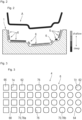
- the resin molding mold 1 according to the embodiment is manufactured by the resin molding mold manufacturing system shown in FIG. 1 .
- the resin molding mold manufacturing system S includes a three-dimensional scanner SC (to also be referred to as a 3D scanner) scanning an uneven sample to make data, a personal computer PC storing three-dimensional data obtained from the three-dimensional scanner SC and performing appropriate processing, and a laser processing machine LP controlled by the personal computer PC.
- a three-dimensional scanner SC to also be referred to as a 3D scanner
- a personal computer PC storing three-dimensional data obtained from the three-dimensional scanner SC and performing appropriate processing
- a laser processing machine LP controlled by the personal computer PC.
- the recesses and projections forming step which gives the recesses and projections 6 to the mold raw material 10, as shown in FIG. 1 is performed by using the laser processing machine LP.
- the laser processing machine LP is connected to the personal computer PC to give the predetermined recesses and projections 6 to the surface of the mold raw material 10 on the basis of the data.
- the recesses and projections 6 formed in the recesses and projections forming step is based on data obtained by scanning the uneven sample M with the three-dimensional scanner SC serving as a scanner in advance. As a matter of course, in addition to the data obtained by scanning, data stored in the personal computer PC in advance can also be used.
- the uneven sample M is a so-called sample having the recesses and projections 6 desired to be given to the surface of a resin molded product.
- the surface of the uneven sample M is scanned by a method or the like in which, for example, image data from a plurality of directions to specify a three-dimensional shape of the surface.
- Data related to the scanned uneven sample M is transferred to the personal computer PC connected to the three-dimensional scanner SC.
- a destination to which the three-dimensional scanner SC transfers the data is not limited to the personal computer PC, a server computer or the like installed at a different position on the network may be used.
- Various existing methods may be conceived.
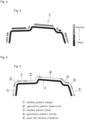
- the personal computer PC can appropriately process the data received from the three-dimensional scanner SC. More specifically, the personal computer PC, by using image editing software, can connect patterns of the different types of installed recesses and projections 6 to each other apparently naturally as shown in FIG. 3 .
- the data related to the recesses and projections 6 exhibits a function of creating a recess portion having a shape successively changed from, for example, a circular shape to a rectangular shape while a change in shape between adjacent recess portions is reduced.
- pattern forming data of the recesses and projections 6 by using the pattern image editing software of the any recesses and projections 6 of different types is created and edited, partial change or the like can be easily performed.
- the resin molding mold manufacturing system S which can manufacture a resin molded product A having an unrestricted surface design is achieved.
- ups and downs to be formed on the surface of the resin molded product A appropriately change in size depending on locations.
- the resin molding mold manufacturing system S is to achieve the recesses and projections forming step to manufacture the resin molding mold 1.
- the recesses and projections forming step is one step in the method of manufacturing the resin molding mold 1 according to the embodiment. A method of manufacturing the resin molded product A will be described later.
- the mold raw material 10 can function as the resin molding mold 1 in the state in which processing by the laser processing machine LP is performed.
- the mold raw material 10 when the thickness of the resin layer 4 disposed on the mold raw material 10 is set to 50 to 800 ⁇ m, the mold raw material 10 can be used as not only the resin molding mold 1, and the recesses and projections 6 is formed on the surface of the resin layer 4, so that a desired surface shape, i.e., a surface having a desired texture can be set.
- the mold raw material 10 which can also function as the resin molding mold 1 which does not form the recesses and projections 6 will be described with reference to FIG. 6 to FIG. 9 .
- the resin molding mold 1 is characterized by including the mold main body 2, as shown in FIGS. 6 to 9 , and the resin layer 4 which is exposedly formed on a mold surface 22 side of the mold main body 2, is made of a heat-resistant complex material containing the synthetic resin 4a and the ceramic powder particle 4b, and has a thickness of 50 to 800 ⁇ m.
- the mold main body 2 itself can be preferably used as a mold for molding a resin.
- the resin layer 4 is arranged on the mold surface 22 on one surface side used in resin molding on the mold main body 2.
- the synthetic resin 4a cured at a low temperature of 200°C or less is used.
- a mold material used as the mold main body 2 various existing material can be applied.
- a raw material except for a metal may be used as the mold raw material, a raw material forming a porous shape as an entire mold material or as a surface shape may be used.
- even the metal raw material may be formed by an existing selective laser sintering method by means of a 3D printer.
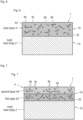
- the resin layer 4, as shown in FIG. 6 to FIG. 9 may include a single layer, two layers, or three layers as long as the layer 4 is formed on the mold surface 22 side of the mold main body 2.
- the resin molding mold 1 having a single layer as the resin layer 4 is shown in FIG. 6 .
- the resin molding mold 1 having two layers as the resin layer 4 is shown in FIG. 7 .
- the resin molding mold 1 having three layers as the resin layer 4 is shown in FIG. 8 and FIG. 9 .
- a first layer 42, a second layer 44, a third layer 46, and a mirror surface coating material layer 48 are shown.
- the resin layer 4 is a so-called heat-resistant complex material containing the synthetic resin 4a and the ceramic powder particle 4b, in manufacturing, diluent solvent 4c.
- the resin layer 4 may be configured by not only a single layer but also a plurality of layers, and the entire thickness of the resin layer 4 may be 50 to 800 ⁇ m.
- the resin layer 4 shown in FIG. 6 to FIG. 8 further contains inorganic fibers 4d.
- the mirror surface coating material layer 48 shown in FIG. 9 is made of a mirror surface coating material.
- the diluent solvent 4c is evaporated to make the completed resin molding mold 1 free from the diluent solvent 4c. However, in the drawing, for descriptive convenient, the diluent agent 4c is also shown.
- the synthetic resin 4a is a main component of the resin layer 4.
- the synthetic resin 4a fulfills a role of keeping the resin layer 4 in a predetermined shape while mixing the ceramic powder particle 4b and the inorganic fibers 4d.
- a resin such as an epoxy resin, an acrylic resin, a polyacetal resin, polyamide resin, a polyimide resin, a polyurethane resin, a polyester resin, a polyethylene resin, polycarbonate resin, a polypropylene resin, a silicon resin, a fluoro resin, a melamine resin, a urea resin, a phenolic resin, a phthalic resin, a styrene resin, a cellulose resin, a vinyl chloride resin, a vinyl acetate resin may be solely used, or a mixture thereof may be used.
- the ceramic powder particle 4b corresponds to an aggregate to give desired strength to the resin layer 4. More specifically, the ceramic powder particle 4b gives strength to external force in a direction in which the resin layer 4 is compressed.
- the ceramic powder particle 4b accounts for 45 to 65% of the entire resin layer 4.
- the ceramic powder particle 4b more preferably accounts for 50 to 60% of the entire resin layer 4, and still more preferably 52 to 57% of the entire resin layer 4.
- As the ceramic powder particle 4b alumina or ceramic is used, and a powder particle having a grain diameter of 0.1 to 70 ⁇ m is desirably used.
- the ceramic powder particle 4b has a porous shape, and can adsorb gas generated in a resin molding state from an exposed surface part.
- the diluent solvent 4c in the embodiment, an organic solvent such as ethyl cellosolve monoacetate which is ordinarily lowly-volatile is used.
- ethyl cellosolve monoacetate which is ordinarily lowly-volatile is used.
- the diluent solvent 4c evaporates in manufacturing, not only the ethyl cellosolve monoacetate but also various existing volatile solvents can be applied.
- the diluent solvent 4c almost entirely evaporates and does not remain in the resin layer 4. However, for descriptive convenience, the diluent solvent 4c is shown in FIG. 6 to FIG. 9 .
- the inorganic fibers 4d is to give desired strength to the resin layer 4 together with the ceramic powder particle 4b.
- the inorganic fibers 4d which is different from the ceramic powder particle 4b, gives strength to external force in a tensile direction to the resin layer 4.
- the inorganic fibers 4d such as glass fibers, carbon fibers, and silicone carbide fibers can be given.
- fibers which are generally referred to as staple fibers, have a fiber length of 5 to 200 ⁇ m, and a fiber diameter of 0.05 to 1.5 ⁇ m are used.
- the first layer 42 and the second layer 44 are formed by a heat-resistant complex material obtained by combining the first layer 42, the ceramic powder particle 4b, the inorganic fibers 4d, and the diluent solvent 4c to each other.
- the first layer 42 and the second layer 44 are different from each other in a compounding ratio of the ceramic powder particle 4b and the inorganic fibers 4d. More specifically, in the embodiment, since the first layer 42 is directly applied on the mold surface 22 of the mold main body 2, fixing force enough to reliably apply the first layer 42 to the mold main body 2 is required. In the configuration shown in FIG.
- the third layer 46 is maximally exposed to the outside.
- the third layer 46 is made of a heat-resistant complex material obtained by combining the synthetic resin 4a and the ceramic powder particle 4b to each other.
- the third layer 46 does not contain the inorganic fibers 4d, or, if contain the inorganic fibers 4d, has a content lower than in the second layer 44.
- the mirror surface coating material layer 48 contains a mirror surface coating material as a main component.
- a mirror surface coating material for example, by using a thermosetting resin having a heat conductivity of 0.10 W/m•k or more and 0.99 W/m•k or less, the mirror surface coating material layer 48 is formed.
- a thermosetting resin used for the mirror surface coating material layer 48 a material having a high thermal insulation is used.
- a thermosetting resin having a heat conductivity of 0.10 W/m•k or more and 0.99 W/m•k or less is used as the thermosetting resin used for the mirror surface coating material layer 48.
- thermosetting resin using the mirror surface coating material layer 48 a phenol resin, an alkyd resin, a melamine urea resin, an epoxy resin, a polyurethane resin, a silicone resin, a chlorinated rubber resin, a vinyl acetate resin, an acrylic resin, a vinyl chloride resin, a fluorocarbon resin, cellulose, a polystyrene resin, or the like is used, and both a simple substance and a copolymer can be used.
- the resin molding mold 1 having the resin layer 4 of the single-layer type 1a is excellent in strength and durability.
- the resin layer 4 including the resin molding mold 1 of the two-layer type 1b, as shown in FIG. 7 is the resin layer 4 having a mode in which the shape of the surface of the second layer 44 is reflected on the resin molded product A while the first layer 42 is strongly fixed to the mold surface 22 of the mold main body 2.
- the surface shape of the molded resin molded product A in other words, the texture of the surface is different from that of the resin molding mold 1 having the resin layer 4 included in the resin molding mold 1 of the single-layer type 1a.
- the heat-resistant complex material configuring the resin layer 4 has a gloss level which increases when the contents of the ceramic powder particle and the inorganic fibers are reduced.
- the surface shape of the molded resin molded product A that is, the texture of the surface is different from those in the resin molding molds 1 having the resin layers 4 of the single-layer type 1a, the second-layer type 1b, or the three-layer type (2) 1c2.
- the recesses and projections 6 is formed on the surface of the resin layer 4 to make it possible to make the resin molding mold 1 having a surface shape different from those in the resin molding molds 1 shown in FIG. 6 to FIG. 9 .
- the resin molding mold 1 before the recesses and projections 6 is formed on the surface of the resin layer 4 fulfills the role of the mold raw material 10.
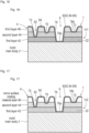
- the resin molding mold 1, according to the embodiment, including the resin layer 4 in which the recesses and projections 6 is formed will be described below with reference to FIG. 10 to FIG. 13 .
- the resin molding mold 1 of the single-layer type 1a including the resin layer 4 in which the recesses and projections 6 is formed is shown in FIG. 10 .
- the resin molding mold 1 of the two-layer type 1b including the resin layer 4 in which the recesses and projections 6 is formed is shown in FIG. 11 .
- the resin molding mold 1 of the three-layer type (1) 1c1 including the resin layer 4 in which the recesses and projections 6 is formed is shown in FIG. 12 .
- the resin molding mold 1 of the three-layer type (2) 1c2 including the resin layer 4 in which the recesses and projections 6 is formed is shown in FIG. 13 .
- the resin molding molds 1 shown in FIG. 10 to FIG. 13 correspond to FIG. 6 to FIG. 9 , respectively.
- the recesses and projections 6 is formed on only the resin layer 4.
- the formation of the recesses and projections 6 does not influence the shape of the mold main body 2 at all.
- the change of the recesses and projections 6 can be achieved by replacing the resin layers 4 without replacing the mold main body 2.
- trial manufacture of the resin layer 4 in which the recesses and projections 6 being capable of expressing a desired surface shape is achieved can be repeatedly performed by means of the same mold main body 2 without replacing the mold main bodies 2 while appropriately using the resin layers 4 in FIG. 6 to FIG. 9 and the resin layers 4 having other configurations. This contributes to a reduction in number of parts related to the trial manufacture of the resin molding mold 1 and to saving troubles.
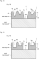
- the recesses and projections 6, as shown in FIG. 10 to FIG. 13 has a tapered recess portion 62 and a tapered projection portion 64.
- the tapered recess portion 62 is a recess obtained by appropriately digging the resin layer 4.
- the tapered recess portion 62 has a bottom surface 70.
- the bottom surface 70 has a mold bottom surface 78a exposing the mold surface 22 of the mold main body 2 and a resin bottom surface 78b formed by any one of the resin layers 4.
- the tapered projection portion 64 is a portion interposed in the tapered recess portion 62. That is, the tapered projection portion 64 is a portion projecting from the bottom surface 70.
- each of the tapered recess portion 62 and the tapered projection portion 64 has a radial portion 72 and a cutout end face 76.
- the radial portion 72 is a radial surface formed between the upper end of the projection portion and the bottom surface 70 at the lower end.
- the cutout end face 76 is an exposed portion of the section of the resin layer 4 formed by digging the resin layer 4.
- the cutout end face 76 has various angles set depending on the shapes of the tapered recess portion 62 and the tapered projection portion 64.
- the recesses and projections 6 shown in FIG. 10 to FIG. 13 has the tapered recess portion 62 tapered toward the mold surface 22 and the rounded (curved) radial portion 72.
- a removing step in manufacture of the resin molded product A can be smoothly performed.
- an angle facing the cutout end face 76 functions as a so-called “draft angle” when the resin molded product A is manufactured.
- the pattern depth of the recesses and projections 6 which can suppress scratches, i.e., so-called galling in removement of a molded product, that is, the arrangement of the mold bottom surface 78a and the depth position of the resin bottom surface 78b can be determined randomly.
- an any depth position of the resin bottom surface 78b sets the pattern depth of the any recesses and projections 6.
- the angle of the cutout end face 76 is appropriately set to make it possible to arbitrarily set the pattern depth of the recesses and projections 6 suitable for a draft angle set for each portion of the mold.
- the recesses and projections 6 is formed on the first layer 42.
- the position of the resin bottom surface 78b in the thickness direction of the resin layer 4 can be adjusted suitably and, in the range of the thickness of the resin layer 4, an appropriate combination of the mold bottom surface 78a serving as the deepest bottom surface 70 and the resin bottom surfaces 78b set at various depths forms the tapered recess portions 62 and the tapered projection portions 64, which have various shapes.
- the resin molding mold 1 (single-layer type 1a) having the single resin layer 4 is excellent in strength and durability while making the quality of the surface of the resin molded product A high.
- the recesses and projections 6 is formed over the first layer 42 and the second layer 44.
- the first layer 42 fulfills a role of an adhesive layer to the mold surface 22, and the second layer 44 has, e.g., a content of the inorganic fibers 4d which is smaller than that of the first layer 42 to obtain characteristics which are excellent in processability of laser processing.
- the second layer 44 contains the ceramic powder particle 4b serving as a porous material and having higher capability to absorbing gas generated in molding of the resin molded product A than that of the ceramic powder particle 4b in the first layer 42.
- the second layer 44 has a surface structure in which gas generated in molding of the resin molded product A easily escapes outside. As shown in FIG. 11 , the position of the resin bottom surface 78b in the thickness direction of the resin layer 4 can be suitably adjusted as in FIG. 10 .
- the recesses and projections 6 is formed over the first layer 42, the second layer 44, and the third layer 46.
- the first layer 42 fulfills the role of an adhesive layer to the mold surface 22, and the second layer 44 has characteristics which are excellent in processability of laser processing by making the content of, for example, the inorganic fibers 4d smaller than that in the first layer 42.
- the third layer 46 for example, has a content of the inorganic fibers 4d further smaller than that in the second layer 44 or does not contain the inorganic fibers 4d to have processability of laser processing which is better than that of the second layer 44. More specifically, the third layer 46 forms a fine surface shape which suppresses a skin layer from being formed at a flow end of a molded resin.
- a cutout end face 76 of the recesses and projections 6 is formed by exposing the first layer 42, the second layer 44, and the third layer 46, by exposing the second layer 44 and the third layer 46, or by exposing only the third layer 46.
- the resin bottom surface 78b is formed by exposing the first layer 42, by exposing the second layer 44, or by exposing the third layer 46. As shown in FIG. 12 , the position of the resin bottom surface 78b in the thickness direction of the resin layer 4 can be suitably adjusted as in FIG. 10 and FIG. 11 .
- the mirror surface coating material layer 48 also serves as a low-friction layer which reduces resin friction in molding.
- desired gloss on the surface of the resin molded product A is provided by the mirror surface coating material layer 48, and the cutout end face 76 of the recesses and projections 6 which can smoothly perform the removing step has surfaces that the first layer 42, the second layer 44, and the mirror surface coating material layer 48; the second layer 44 and the mirror surface coating material layer 48; and only the mirror surface coating material layer 48 are respectively exposed.
- the resin bottom surface 78b has surfaces that the layer 42, exposes the layer 44, and expose the mirror surface coating material layer 48 are exposed. As in FIG. 13 , the position of the resin bottom surface 78b can be suitably adjusted in the thickness direction of the resin layer 4 as in FIG. 10 to FIG. 12 .
- the ratio of the inorganic fibers 4d progressively decreases when the resin layers 4 are progressively laminated from the mold surface 22 of the mold main body 2.
- the ratio of the inorganic fibers 4d progressively decreases when the plurality of resin layers 4 are laminated from the mold surface 22 of the mold main body 2, and, on the resin layer 4 farthest from the mold surface 22, the mirror surface coating material layer 48 (three-layer type (2) 1c2) which does not contain the inorganic fibers 4d (three-layer type (1) 1c1) or is made of a different material is formed.
- the surface can be independently coated. More specifically, a surface coating layer can be further formed on the surface of the resin layer 4.
- a coating layer 8 is a matte layer 82, a mirror surface coating layer 84, or a gloss adjusting layer 86.
- a surface coating having another function can also be applied.
- a matte layer to which various gloss adjusting particles are added and which is different from the above-mentioned matte layer may be configured.
- the degree of gloss of the resin molded product A manufactured by the resin molding mold 1 can be adjusted to a desired degree of gloss while satisfying the adhesiveness of the resin layer 4 to the mold main body 2 made of metal and the reproducibility of the uneven sample M by laser processing.
- the mold raw material 10 which has the resin layer 4 of a different type and can reproduce the surface shape of the uneven sample M shown in FIG. 1 is selected, and a desired frosting process can also be applied to a product in which the shape of the uneven sample M (see FIG. 1 ) is reproduced most faithfully,
- the resin layer 4 containing many inorganic fibers 4d and a plenty of ceramic powder particle 4b tends to have high strength and to be excellent in adhesiveness to the mold surface 22 of the mold main body 2 made of metal.
- the content of the inorganic fibers 4d or the ceramic powder particle 4b becomes low, the laser processability is improved, and the recesses and projections 6 which is more faithful to the sample may be processed.
- the resin molding mold 1 as described above depending on the surface shape of the uneven sample M (see FIG. 1 ), the resin molded product A which is more faithfully reproduced can be manufactured.
- the recesses and projections 6 is not limited to a recesses and projections having a curved surface forming the recesses and projections 6.
- each of the recesses and projections 6 shown in FIG. 10 to FIG. 17 has the tapered recess portion 62 and the radial portion 72 to form a smoothly tapered shape, to have a shape tapered toward the mold surface 22, and to be cornerless (rounded).
- the recesses and projections 6 as shown in FIG. 18 and FIG. 19 may be used.
- the resin molded product A which faithfully represents the recesses and projections 6 can be manufactured.
- the direction of the cutout end face 76 is a direction parallel to the surface direction of the mold surface 22 of the mold main body 2.
- a mode in which the cutout end face 76 vertical to one surface is formed is shown in FIG. 19 , as a matter of course, a mode in which the cutout end face 76 is inclined at a small angle as a "draft angle" in design is also included.
- the resin molded product A which faithfully represents the recesses and projections 6 can be manufactured.
- the recesses and projections 6 shown in FIG. 18 and FIG. 19 and the recesses and projections 6 (not shown) including the straight recess portion 66, the straight projection portion 68, and the radial portion 72 may further include the surface coating layers 8 shown in FIG. 14 to FIG. 17 .
- the resin molding mold 1 not only surface configuration, but also characteristics such as the presence/absence of laminated layers, the number of laminated layers, the shape of the recesses and projections 6, and the presence/absence of the coating layer 8 are appropriately used to make it possible to give a surface shape having a desired appearance to the resin molded product A.
- the resin molding mold 1 according to the embodiment is preferably produced by the method of manufacturing the resin molding mold 1 according to the embodiment shown in FIG. 20 .
- the manufacturing method is preferably achieved by the resin molding mold manufacturing system S shown in FIG. 1 .
- the method of manufacturing the resin molding mold 1 according to the embodiment is characterized by including the resin layer forming step, the pre-curing step, the main curing step, and the recesses and projections forming step.
- the resin layer 4 made of a heat-resistant complex material containing the synthetic resin 4a, the ceramic powder particle 4b, and the diluent solvent 4c is formed.
- the resin layer forming step in the embodiment, is performed by a spraying method of spraying a resin on, for example, the mold surface 22 of the mold main body 2 to have a predetermined thickness.
- the resin layer forming method is not limited to the spraying method.
- a mode which sticks a resin sheet molded by a slip blade method, a doctor blade method, a roll method performing molding by using a roll in place of a doctor blade in the doctor blade method, a calendar method, a paper dipping method, a continuous pressing method, an injection molding method, a slice method slicing a block of mold, a squeeze method, a drawing method drawing a semi-cured resin, a shaving method shaving a block of resin, a press molding method, a centrifugal method drawing a resin by centrifugal method, and an extrusion molding method extruding a resin from an extruder in the form of sheet can be given.
- the resin layer 4 is heated for a predetermined period of time and kept at a predetermined temperature to temporarily cured a resin raw material.
- the temperature in the pre-curing step is set at 80°C.
- the recesses and projections forming step the recesses and projections 6 having a predetermined shape is formed on the resin layer 4 formed in the resin layer forming step.
- the recesses and projections forming step is performed by irradiating a laser beam as shown in FIG. 1 .
- the coating layer forming step to form another coating layer may be performed.
- the coating layer forming step is a step of forming a predetermined surface coating layer 8 on the recesses and projections 6 (see FIG. 14 to FIG. 17 ).
- the coating layer forming step is performed, more specifically, such that a predetermined coating agent is sprayed on the surface of the recesses and projections 6 by a spraying process, and, thereafter, the recesses and projections 6 is held at 150°C for 2 hours in a heating furnace to cure the matte layer 82 serving as a coating agent, the mirror surface coating layer 84, or the gloss adjusting layer 86.
- steps of forming the resin layer 4 having the recesses and projections 6 according to FIG. 10 to FIG. 19 to complete the resin molding mold 1 will be described with reference to the flow chart in FIG. 20 .
- the steps include step ST11 to step ST17.
- a main body of these steps is an operator who performs processes to the mold main body 2 in the steps.
- step ST11 the operator forms the resin layer 4 by spraying or the like on the mold surface 22 side of the mold main body 2. More specifically, the operator performs the resin layer forming step. The process shifts to step ST12. More specifically, on the mold surface 22 of the resin molding mold, by using a spray gun, a resin (configuring the first layer 42, the second layer 44, the third layer 46, or the mirror surface coating material layer 48) is sprayed.
- step ST12 the operator temporarily cures the resin layer 4 formed on the mold surface 22 side of the mold main body 2. More specifically, the operator performs the pre-curing step. The process shifts to step ST13. More specifically, in step ST12, the sprayed resin is temporarily cured.
- step ST14 the operator fully cures the resin layers 4 formed as a single layer or a plurality of layers. More specifically, the operator the main curing step described above. At this stage, the mold raw material 10 is completed. The mold raw material 10, as described above, can also directly used as the resin molding mold 1. The process shifts to step ST15. Thereafter, a step of polishing and adjusting the laser-processed surface of the resin layer 4 and uniforming a resin thickness from the mold surface 22 (removing surface waviness) may be set.
- step ST16 the operator determines whether a coating layer is further formed on the resin layer 4 on which the recesses and projections 6 is formed.
- the process shifts to step ST17.
- the operator determines that the coating layer is not formed (No in step ST17)
- the process ends.
- step ST17 the operator further forms a coating layer on the surface of the formed recesses and projections 6. More specifically, the operator performs the coating layer forming step. The process ends. That is, in step ST17, as needed, the surface coating layer 8 (the matte layer 82, the mirror surface coating layer 84, or the gloss adjusting layer 86) serving as an additional layer is formed by the spraying process.
- the surface coating layer 8 the matte layer 82, the mirror surface coating layer 84, or the gloss adjusting layer 86
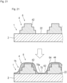
- the resin layer 4 is the resin molding mold 1 of the single-layer type 1a in which the recesses and projections 6 is formed on the first layer 42.
- the second layer 44 (or may be the mirror surface coating material layer 48) is further formed on the resin molding mold 1 in which the recesses and projections 6 shown in the upper part of FIG. 21 is formed by a laser beam to form the recesses and projections 6 which is entirely different from the recesses and projections 6 shown in FIG. 10 to FIG. 19 .
- the recesses and projections 6 shown in the lower part of FIG. 21 has a rolling which is gentle more than those of the recesses and projections 6 shown in FIG. 10 to FIG. 19 .
- the recesses and projections 6 shown in the lower part of FIG. 21 is formed by the surface shape of the uneven (the recesses and projections) sample M (see FIG. 1 )
- the resin molded product A having a surface shape being more faithful to the uneven sample M may be able to be obtained.
- the steps include step ST21 to step ST27.
- a main body of these steps is an operator which performs processes in the steps to the mold main body 2.
- step ST21 the operator forms the resin layer 4 by performing spraying or the like on the mold surface 22 side of the mold main body 2 is performed. The process shifts to step ST22.
- step ST22 the operator temporarily cures the resin layer 4 formed on the mold surface 22 side of the mold main body 2. More specifically, the operator performs the pre-curing step. The process shifts to step ST23.
- step ST23 the operator fully cures the resin layer 4 formed as a single layer. More specifically, the operator performs the main curing step. At this stage, the mold raw material 10 is completed.
- the mold raw material 10, as described above, can also be directly used as the resin molding mold 1. The process shifts to step ST24.
- step ST24 the operator operates the laser processing machine LP shown in FIG. 1 to form the recesses and projections 6 on the resin layer 4 formed on the mold raw material 10. More specifically, the recesses and projections forming step is performed. The process shifts to step ST25.
- step ST26 the operator temporarily cures the resin layer 4 formed on the mold surface 22 side of the mold main body 2. More specifically, the operator performs the pre-curing step. The process shifts to step ST27.
- step ST27 the operator fully cures the resin layer 4 formed as a single layer or a plurality of layers. More specifically, the operator the main curing step. At this stage, the mold raw material 10 is completed. The mold raw material 10, as described above, can be directly used as the resin molding mold 1. The process ends. As a matter of course, after step ST27, the coating layer 8 is further formed.
- the resin molding mold 1 which can obtain the resin molded product A on which the desired recesses and projections 6 is formed can be provided.
- the resin molded product A having a desired surface shape can be obtained.
- the method of manufacturing the resin molded product A according to the embodiment has the resin filling step, a mold resin curing step, and the removing step.
- the molding resin curing step is a step of curing the molding resin after the resin filling step. More specifically, various existing methods such as curing of a resin by a decrease in temperature and curing of a resin by UV irradiation can be applied.
- the removing step is a step of removing the cured molding resin from the resin molding mold 1. In the removing step, thereafter, the step of performing appropriate processing to the resin molded product A removed from the resin-molded mold 1 to obtain a final product a user requires is not denied.
- a main body of the steps is a user who obtains the resin molding molds 1 according to the embodiment and the modification by purchasing or the like to use the resin molding mold 1.
- the steps include step ST31 to step ST33.
- step ST31 the user fills a liquid molding resin into the resin molding mold 1. More specifically, the user performs the resin filling step. The process shifts to step ST32.
- step ST33 the user removes the molding resin filled in the resin molding mold 1 to obtain the resin molded product A according to the embodiment. More specifically, the user performs the removing step. The process ends.
- the ceramic powder particle 4b exposed to the mold surface 22 side effectively adsorbs gas generated in resin molding. In this manner, nonuniformity of quality of the resin product can be effectively suppressed.
- the thickness of the resin layer 4 is set to 50 to 800 ⁇ m, surface processing is additionally performed to a desired position of the resin layer 4 to make it possible to give a desired surface shape to the resin molded product A.
- the resin molding mold 1 which can manufacture the resin molded product A having the desired surface shape can be provided.
- the heat-blocking effect obtained by the resin layer 4 improves the fluidity of the molding resin to obtain an advantage which makes the occurrence of defective molding less.
- the fine unevenness obtained by ceramic powder contained in the resin layer 4 serves as an escapeway for gas generated in molding.
- the ceramic powder itself serving as a porous material contained in the resin layer 4 absorbs gas generated in molding, defective molding caused by gas does not easily occur.
- a multi-layered structure is made of a resin different from that of the resin layer 4, a skin layer formation suppressing effect of the molding resin can be obtained, and the resin molded product A having less defective appearance and a high reversal rate of the uneven pattern can be obtained.
- an etching process is performed by a photoetching method.
- a pattern mask made of a polyester film or the like is cut in, in tight contact with the mold along the mold shape, and exposed to form an acid-proof pattern. For this reason, a seam or an unnatural line may be formed.
- the resin-molded mold 1 according to the embodiment the resin molded product A which forms a high-quality surface shape without a seam and an unnatural line can be provided.
- data in the personal computer PC is brought in while using the uneven sample M as a motif, and the motif and the data are seamlessly processed by software stored in the personal computer so as to achieve the shape of the high-design recesses and projections 6.
- the resin molding mold 1 since the resin layer 4 is partially dug to form the recesses and projections 6, the resin-molded mold 1 to which a unique texture such as embossing is given is provided. As a result, the resin molding mold 1 which can stably manufacture a resin product having a desired surface shape is provided.
- the recesses and projections 6 is formed on only the resin layer 4. More specifically, since a mold itself is not processed unlike an etching process, reprocessing can be easily performed (as long as the resin layer 4 is peeled and reformed). In addition, a pattern formed by the recesses and projections 6 can be formed on an unintended recesses and projections 6 formed by corrosion or a molding mold made of a material increasing in surface roughness by a hollow.
- the recess portion forming the recesses and projections 6 has the recess portion of the mold surface 22 in which the bottom surface 70 is obtained by exposing the mold surface 22 of the mold main body 2 and a resin recess portion having the bottom surface 70 in the resin layer 4.
- the resin layer 4 has a plurality of layers having different ratios of the synthetic resin 4a and the ceramic powder particle 4b, and end faces of the plurality of layers are exposed at a position where the recesses and projections 6 is formed, so that the characteristics of the layers are made different from each other. In this manner, problems such as generation of gas occurring in molding of the resin molded product A and a defective flow of a molding resin which are posed in conventional resin molding are solved to achieve molding of the resin molded product A having higher quality.
- any one of the resin layers 4 further includes the inorganic fibers 4d, and the inorganic fibers 4d have fiber lengths of 5 tom 200 ⁇ m and fiber diameters of 0.05 to 1.5 ⁇ m.
- the ratio of the inorganic fibers 4d decreases when the plurality of resin layers 4 are laminated from the mold surface 22 of the mold main body 2.
- the mirror surface coating material layer 48 which does not include the inorganic fibers 4d is applied to the resin layer 4 farthest from the mold surface 22 (see FIG. 9 and FIG. 13 ).
- the surface costing layer 8 is formed on the surface of the resin layer 4 (see FIG. 14 to FIG. 17 ).
- the resin layer 4 contains 45 to 65% ceramic powder particle 4b.
- the grain diameter of the ceramic powder particle 4b is set to 0.1 to 70 ⁇ m, absorption of gas generated in molding or texture of a degree of matte of the surface of a molded product become preferable.
- the resin molding mold 1 having a surface to which unique texture such as embossing is given is provided.
- the resin molding mold 1 which can stably manufacture a resin product having a desired surface shape can be provided.
- ethyl cellosolve monoacetate which is generally known to have a volatilization rate lower than that of another ordinary solvent is used to achieve high workability in manufacturing of the resin molding mold 1.
- the recesses and projections forming step is performed by irradiating a laser beam. More specifically, by using the laser processing machine LP, formation of a pattern (embossing pattern) of the recesses and projections 6 is achieved at a pattern depth of the any recesses and projections 6 suitable for a draft angle is easily achieved. More specifically, by using the laser processing machine LP, the pattern (embossing pattern) of the recesses and projections 6 is formed at a pattern depth of the any recesses and projections 6 suitable for a draft angle of a mold is easily formed.
- a laser beam emitted by any one of a carbon dioxide gas laser processing machine LP, a fiber laser processing machine LP, a femtosecond laser processing machine LP, a blue laser processing machine LP, a green laser processing machine LP, and a multi-wavelength composite laser processing machine LP which can coaxially irradiate at least two wavelengths emitted from laser oscillators is used, the resin molding mold 1 which can manufacture the resin molded product A having a desired surface shape is achieved.
- the resin layer forming step and the pre-curing step are performed to each of the plurality of resin layers 4.
- the recesses and projections 6 formed in the recesses and projections forming step is based on data obtained by scanning the uneven sample M (see FIG. 1 ) with a scanner.
- the resin molding mold manufacturing system S is the resin molding mold manufacturing system S to manufacture the resin molding mold 1 by giving the recesses and projections 6 to the mold surface 22 of the mold raw material 10 to manufacture the resin molded product A includes the mold raw material 10, a scanner, and the laser processing machine LP and includes the scanning step of scanning the surface shape of the uneven sample M (see FIG. 1 ) with a scanner and the laser processing step of processing the surface of the mold raw material 10.
- the method of manufacturing a resin molded product according to the present invention has the resin filling step, the resin curing step, and the removing step to make it possible to provide the high-quality resin molded product A by using any one of the resin molding molds 1 described above.
- the "high-quality” is a molded product having reduced defective appearance and the high-design (having an uneven pattern which is not easily manually formed) resin molded product A.
- Example 1 manufacturing procedures of a resin molding mold corresponding to the flow chart shown in FIG. 20 according to the embodiment will be further concretely explained.
- Degreasing and washing for a mold surface is performed with an organic solvent such as tetrachloroethylene, methanol, or thinner.
- a part where a resin layer is not formed is masked with a predetermined masking material, a gummed tape, or the like.
- An epoxy resin (80 parts by weight of a synthetic resin, 50 parts by weight of ceramic powder, 10 parts by weight of inorganic fiber, and 50 parts by weight of diluent solvent) is sprayed by using a spray gun, and dried and temporarily cured until the diluent solvent is evaporated. This procedure corresponds to steps ST11 and ST12 in FIG. 20 .
- the surface to be irradiated with a laser of the formed resin layers is polished, adjusted to make a resin thickness from the mold surface uniform (remove surface waviness).
- Uneven pattern processing data created in advance is mapped (positioning and confirmation of pattern) in accordance with a mold shape, and an uneven pattern is formed by a laser processing machine. This procedure corresponds to step ST15 in FIG. 20 .
- a part where the additional layer is not formed is masked with a predetermined masking material, a gummed tape, or the like.
- An additional layer (70 parts by weight of synthetic resin, 15 parts by weight of matte agent, and 15 parts by weight of diluent solvent) is formed by a spraying process and cured in a heating furnace (kept at 150°C for 2 hours). This procedure corresponds to step ST17 in FIG. 20 .
- a mold raw material 10 is prepared, and the shape of the mold raw material is scanned with a three-dimensional scanner SC serving as a scanner. Scanned data is stored in the personal computer PC connected to the three-dimensional scanner SC.
- the step is the mold raw material scanning step.
- an uneven sample M is prepared, at least a surface shape of the uneven sample (M) is scanned with the three-dimensional scanner SC serving as a scanner.
- the scanned data is stored in the personal computer PC connected to the three-dimensional scanner SC.
- the step corresponds to the scanning step of scanning the surface shape of the uneven sample M with the three-dimensional scanner SC.
- data related to the mold raw material 10 and one or a plurality of uneven samples M and stored in the personal computer PC and storage data stored in the computer PC in advance and related to the surface shape are combined to each other.
- the personal computer PC sets a position where the data related to the uneven sample M is reflected on the parts of the mold raw material 10 (see FIG. 1 and FIGS. 6 to 9 ) and sets a surface shape related to the storage data to a position except for the position.
- a specific program which can forms a continuous shape obtained by connecting the surface shape related to the data related to the uneven sample M to the surface shape related to the storage data as if there is no seam is stored (see FIG. 3 ).
- a concrete shape of the recesses and projections 6 to be given to the mold raw material is set.
- the step is the uneven data editing step which can be performed next to the scanning step.
- the laser processing machine LP is controlled depending on data scanned and edited in the scanning step and the uneven data editing step, and the surface of the mold raw material 10 is processed.
- the femtosecond laser processing machine having an output of 20 W is applied as the laser processing machine LP to process the uneven data.
- the depth of the recesses and projections 6, i.e., the shape of the recesses and projections 6 concretely formed in the mold raw material 10 can be adjusted by appropriately changing settings such as the output and the frequency of the femtosecond laser processing machine.
- the step corresponds to the laser processing step of controlling the laser processing machine depending on the data scanned in the scanning step to process the surface of the mold raw material.
- the resin molding mold manufacturing system S according to the embodiment, the personal computer PC is utilized while using one or a plurality of uneven samples M and existing data to make it possible to form a desired recesses and projections 6 on the mold raw material 10.
- the invention relates to a resin molding mold and can be used in a resin molding mold to perform resin molding used when a resin molded product having, on the surface, an embossed pattern (leather texture, skin texture, wood texture, pear skin texture, vein texture, scale texture, marble texture, mirror finish, finish coating, geometric patterns, and the like) conditioning the molding surface for improving, in particular, product design, a method for the same, and a resin molded product molded by the resin molding mold.
- an embossed pattern leather texture, skin texture, wood texture, pear skin texture, vein texture, scale texture, marble texture, mirror finish, finish coating, geometric patterns, and the like
Landscapes
- Engineering & Computer Science (AREA)
- Mechanical Engineering (AREA)
- Manufacturing & Machinery (AREA)
- Chemical & Material Sciences (AREA)
- Inorganic Chemistry (AREA)
- Physics & Mathematics (AREA)
- Health & Medical Sciences (AREA)
- Oral & Maxillofacial Surgery (AREA)
- Thermal Sciences (AREA)
- Materials Engineering (AREA)
- Wood Science & Technology (AREA)
- Organic Chemistry (AREA)
- Life Sciences & Earth Sciences (AREA)
- Moulds For Moulding Plastics Or The Like (AREA)
Claims (13)
- Harzgussform, die folgende Merkmale aufweist:einen Gussformhauptkörper (2) undeine Harzschicht (4), die auf einer Seite einer Formoberfläche (22) des Gussformhauptkörpers (2) gebildet und freigelegt ist, wobei die Harzschicht (4) wärmebeständige Verbundmaterialien aufweist, die ein Kunstharz (4a) und ein Keramikpulverpartikel (4b) enthalten; wobeiAussparungen und Vorsprünge (6) auf der Harzschicht (4) durch Aushöhlen eines Abschnitts der Harzschicht (4) gebildet sind, dadurch gekennzeichnet, dassdie Harzschicht (4) eine Mehrzahl von Schichten aufweist, die unterschiedliche Verhältnisse des Kunstharzes (4a) und des Keramikpulverpartikels (4b) aufweist, undeine Endoberfläche der Mehrzahl von Harzschichten (4) dort freigelegt ist, wo die Aussparungen und Vorsprünge (6) gebildet sind.
- Harzgussform gemäß Anspruch 1, bei der
die Aussparungen und Vorsprünge (6) nur auf der Harzschicht (4) gebildet sind. - Harzgussform gemäß Anspruch 2, bei derdie Aussparungen der Aussparungen und Vorsprünge (6) eine Formoberflächenaussparung (78a) und eine Schichtaussparung (78b) enthalten,wobei die Formoberflächenaussparung (78a) durch Freilegen einer Bodenoberfläche (22) des Gussformhauptkörpers (2) erhalten wird, undein Boden der Schichtaussparung (78b) auf der Harzschicht (4) gebildet ist.
- Harzgussform gemäß einem der Ansprüche 1 bis 3, bei der
in den Aussparungen der Aussparungen und Vorsprünge (6) jede Harzschicht eine Bodenoberfläche der Aussparungen aufgrund einer unterschiedlichen Aushöhlungstiefe aufweist. - Harzgussform gemäß einem der Ansprüche 1 bis 4, die ferner eine anorganische Faser (4d) in einer der Harzschicht (4) aufweist, wobei
die anorganische Faser (4d) eine Faserlänge von 0,05 µm bis 200 µm und einen Faserdurchmesser von 0,05 µm bis 80 µm aufweist. - Harzgussform gemäß Anspruch 5, bei der
wenn die Mehrzahl von Harzschichten (4) auf eine Formoberfläche (22) des Gussformhauptkörpers (2) laminiert ist, ein Verhältnis der anorganischen Faser (4d) allmählich klein wird. - Harzgussform gemäß Anspruch 5 oder 6, bei derwenn die Mehrzahl von Harzschichten (4) auf die Formoberfläche (22) des Gussformhauptkörpers (2) laminiert ist, ein Verhältnis der anorganischen Faser (4d) allmählich klein wird, undeine Harzschicht (4), die am weitesten von der Formoberfläche (22) entfernt ist, eine faserfreie Schicht ist, die die anorganische Faser (4d) nicht enthält.
- Harzgussform gemäß einem der Ansprüche 1 bis 7, die ferner eine Beschichtungsschicht aufweist, die auf einer Oberfläche der Harzschicht (4) vorgesehen ist,
wobei die Beschichtungsschicht eine matte Schicht (82), eine Spiegeloberflächenschicht (84) oder eine Glanzanpassungsschicht (86) ist. - Verfahren zum Herstellen einer Harzgussform, wobei das Verfahren folgende Schritte aufweist:einen Harzschichtbildungsschritt eines Bildens, auf einer Formoberfläche (22) eines Gussformhauptkörpers (2), einer Harzschicht (4), die wärmebeständige Verbundmaterialien aufweist, die ein Kunstharz (4a), ein Keramikpulverpartikel (4b) und ein Verdünnungslösungsmittel (4c) enthalten;einen temporären Härtungsschritt eines temporären Härtens von Harzmaterialien durch Erwärmen für eine gegebene Zeit und Aufrechterhalten einer vorbestimmten Temperatur nach dem Harzschichtbildungsschritt;einen Haupthärtungsschritt eines Härtens der Harzmaterialien durch eine Wärmebehandlung der Harzmaterialien; undeinen Aussparungen- und Vorsprünge-Bildungsschritt eines Bildens von Aussparungen und Vorsprüngen (6) einer vorgeschriebenen Form auf der Harzschicht (4), die bei dem Harzschichtbildungsschritt gebildet wird, wobeidie Harzgussform (1) die Mehrzahl von Harzschichten (4) aufweist undder Harzschichtbildungsschritt und der temporäre Härtungsschritt an jeder der Harzschicht durchgeführt werden.
- Verfahren zum Herstellen der Harzgussform gemäß Anspruch 9, bei dem das Verdünnungslösungsmittel (4c) Ethyl-Cellosolve-Monoacetat ist.
- Verfahren zum Herstellen der Harzgussform gemäß Anspruch 9 oder 10, bei dem der Aussparungen- und Vorsprünge-Bildungsschritt unter Verwendung von Laserlichtbestrahlung durchgeführt wird und
das Laserlicht durch eine beliebige von einer Kohlenstoffdioxidgaslaserbearbeitungsmaschine, einer Faserlaserbearbeitungsmaschine, einer Femtosekundenlaserbearbeitungsmaschine, einer Blaulaserbearbeitungsmaschine, einer Grünlaserbearbeitungsmaschine und einer Mehrwellenlängen-Verbundlaserbearbeitungsmaschine abgestrahlt wird, die zwei Typen oder mehr Wellenlängen, die durch eine Laseroszillationsquelle erzeugt werden, koaxial abstrahlt. - Verfahren zum Herstellen der Harzgussform gemäß einem der Ansprüche 9 bis 11, bei dem
die Aussparungen und Vorsprünge (6), die bei dem Aussparungen- und Vorsprünge-Bildungsschritt gebildet werden, auf Daten basieren, die in einer Aussparungen- und Vorsprünge-Probe mit einem Scanner zuvor abgetastet wurden. - System zum Herstellen einer Harzgussform (1) durch Versehen einer Formoberfläche (22) eines Formmaterials mit Aussparungen und Vorsprüngen (6), um ein Harzgussprodukt herzustellen, das folgende Merkmale aufweist:das Formmaterial, das Folgendes aufweist:einen Gussformhauptkörper (2); undeine Harzschicht (4), die auf einer Seite einer Formoberfläche (22) des Gussformhauptkörpers (2) gebildet und freigelegt ist, wobei die Harzschicht wärmebeständige Verbundmaterialien aufweist, die ein Kunstharz (4a), ein Keramikpulverpartikel (4b) und ein Verdünnungslösungsmittel (4c) enthalten, und eine Dicke zwischen 50 µm und 800 µm aufweist;eine Abtastvorrichtung; undeine Laserbearbeitungsmaschine,wobei das System ferner Folgendes aufweist:einen Abtastschritt eines Abtastens, mit der Abtastvorrichtung, einer Oberflächenform von Proben; undeinen Laserbearbeitungsschritt eines Steuerns der Laserbearbeitungsmaschine gemäß Daten, die bei dem Abtastschritt abgetastet werden, und Bearbeitens einer Oberfläche des Formmaterials.
Applications Claiming Priority (1)
| Application Number | Priority Date | Filing Date | Title |
|---|---|---|---|
| PCT/JP2019/050213 WO2021124581A1 (ja) | 2019-12-20 | 2019-12-20 | 樹脂成形用型、樹脂成形用型の製造方法、樹脂成形品の製造方法及び樹脂成形品製造システム |
Publications (5)
| Publication Number | Publication Date |
|---|---|
| EP4079482A1 EP4079482A1 (de) | 2022-10-26 |
| EP4079482A4 EP4079482A4 (de) | 2023-09-20 |
| EP4079482C0 EP4079482C0 (de) | 2025-04-16 |
| EP4079482B1 true EP4079482B1 (de) | 2025-04-16 |
| EP4079482B8 EP4079482B8 (de) | 2025-09-24 |
Family
ID=76476751
Family Applications (1)
| Application Number | Title | Priority Date | Filing Date |
|---|---|---|---|
| EP19956742.1A Active EP4079482B8 (de) | 2019-12-20 | 2019-12-20 | Harzformwerkzeug, verfahren zur herstellung eines harzformwerkzeugs, verfahren zur herstellung eines harzformteils und system zur herstellung eines harzformteils |
Country Status (7)
| Country | Link |
|---|---|
| US (1) | US12441030B2 (de) |
| EP (1) | EP4079482B8 (de) |
| JP (1) | JP7355848B2 (de) |
| KR (1) | KR102846073B1 (de) |
| CN (1) | CN114845848B (de) |
| ES (1) | ES3026733T3 (de) |
| WO (1) | WO2021124581A1 (de) |
Families Citing this family (6)
| Publication number | Priority date | Publication date | Assignee | Title |
|---|---|---|---|---|
| US20220306459A1 (en) * | 2021-03-25 | 2022-09-29 | Tessy Plastics Corporation | Method for forming micro channels in molded components and an associated micro-channel forming tool |
| US12390976B2 (en) | 2021-09-25 | 2025-08-19 | Digimarc Corporation | Signaling arrangements employing molded thermoplastics |
| WO2023107155A1 (en) | 2021-12-08 | 2023-06-15 | Digimarc Corporation | Marking methods and arrangements |
| DE102023206206A1 (de) * | 2023-06-30 | 2025-01-02 | Eschmann Textures International Gmbh | Verfahren zum Herstellen eines Formwerkzeugs, Formwerkzeug und Formteil |
| IT202300014838A1 (it) * | 2023-07-14 | 2025-01-14 | Siti B & T Group Spa | Procedimento per l’ottenimento di tamponi di pressatura rivestiti per la realizzazione di lastre strutturate in materiale ceramico |
| FR3161589A1 (fr) * | 2024-04-30 | 2025-10-31 | Ecole Polytechnique | Moule de fabrication d’au moins un tampon de marquage, tampon et procédé associé |
Family Cites Families (14)
| Publication number | Priority date | Publication date | Assignee | Title |
|---|---|---|---|---|
| CA1312186C (en) * | 1985-12-20 | 1993-01-05 | Hiroyuki Koike | Plastics shaping mold and method of preparing mold |
| NL8802945A (nl) * | 1988-11-30 | 1990-06-18 | Philips Nv | Electronisch telefoontoestel. |
| JP2001062842A (ja) * | 1999-08-31 | 2001-03-13 | Asahi Chem Ind Co Ltd | 艶消し成形品用断熱金型及びその製造方法 |
| JP2005018532A (ja) | 2003-06-27 | 2005-01-20 | Maiku:Kk | 成形型の製造方法および食品型 |
| JP2007160637A (ja) | 2005-12-12 | 2007-06-28 | Tanazawa Hakkosha:Kk | 樹脂成形品 |
| GB0620712D0 (en) * | 2006-10-18 | 2006-11-29 | Flotek Internat Ltd | Method of embssing a substrate |
| CN101563198B (zh) * | 2006-12-01 | 2012-08-22 | 棚泽八光社股份有限公司 | 树脂成型用模具、树脂成型用模具的制造方法及树脂成型品 |
| US9434094B2 (en) | 2011-02-28 | 2016-09-06 | Tanazawa Hakkosha Co., Ltd. | Molding die and method for manufacturing same |
| JP6094668B2 (ja) * | 2014-01-17 | 2017-03-15 | 東レ株式会社 | 被覆繊維強化樹脂成形品の製造方法 |
| JP6043773B2 (ja) | 2014-10-15 | 2016-12-14 | 株式会社アマダホールディングス | ダイレクトダイオードレーザ光による板金の加工方法及びこれを実行するダイレクトダイオードレーザ加工装置 |
| JP2016112609A (ja) | 2014-12-18 | 2016-06-23 | パナソニックIpマネジメント株式会社 | レーザ切断装置およびレーザ切断方法 |
| JP2017007114A (ja) * | 2015-06-17 | 2017-01-12 | エスビック株式会社 | コンクリート二次製品の製造方法 |
| US10124514B2 (en) * | 2015-07-30 | 2018-11-13 | Tanazawa Hakkosha Co., Ltd. | Resin molding mold |
| KR102453211B1 (ko) * | 2015-07-30 | 2022-10-07 | 가부시끼가이샤 다나자와 핫꼬오샤 | 수지 성형용 금형 |
-
2019
- 2019-12-20 EP EP19956742.1A patent/EP4079482B8/de active Active
- 2019-12-20 WO PCT/JP2019/050213 patent/WO2021124581A1/ja not_active Ceased
- 2019-12-20 US US17/787,669 patent/US12441030B2/en active Active
- 2019-12-20 ES ES19956742T patent/ES3026733T3/es active Active
- 2019-12-20 JP JP2021565313A patent/JP7355848B2/ja active Active
- 2019-12-20 KR KR1020227022277A patent/KR102846073B1/ko active Active
- 2019-12-20 CN CN201980103182.6A patent/CN114845848B/zh active Active
Also Published As
| Publication number | Publication date |
|---|---|
| EP4079482C0 (de) | 2025-04-16 |
| EP4079482B8 (de) | 2025-09-24 |
| US20220410437A1 (en) | 2022-12-29 |
| ES3026733T3 (en) | 2025-06-12 |
| CN114845848B (zh) | 2024-09-24 |
| KR102846073B1 (ko) | 2025-08-12 |
| JP7355848B2 (ja) | 2023-10-03 |
| WO2021124581A1 (ja) | 2021-06-24 |
| EP4079482A4 (de) | 2023-09-20 |
| US12441030B2 (en) | 2025-10-14 |
| EP4079482A1 (de) | 2022-10-26 |
| CN114845848A (zh) | 2022-08-02 |
| JPWO2021124581A1 (de) | 2021-06-24 |
| KR20220118441A (ko) | 2022-08-25 |
Similar Documents
| Publication | Publication Date | Title |
|---|---|---|
| EP4079482B1 (de) | Harzformwerkzeug, verfahren zur herstellung eines harzformwerkzeugs, verfahren zur herstellung eines harzformteils und system zur herstellung eines harzformteils | |
| US4752498A (en) | Method and apparatus for production of three-dimensional objects by photosolidification | |
| EP2098349B1 (de) | Formwerkzeug zum harzformen, verfahren zur herstellung des formwerkzeugs zum harzformen und harzgeformtes produkt | |
| CN1236907C (zh) | 精确叠合压纹产品的制造工艺 | |
| CN1720127B (zh) | 生产轮胎硫化模具的方法和轮胎硫化模具 | |
| US7832333B2 (en) | Housing and method for making the same | |
| KR100574268B1 (ko) | 삼차원 조형물의 제조방법 | |
| CN105431791A (zh) | 用于制造三维物体的方法 | |
| JP4612108B2 (ja) | 紙匹成形機用の静電脱水素子及び紙匹成形機用に設計される静電脱水素子を被覆するための方法 | |
| Gibson et al. | Post-processing | |
| Holländer et al. | Surface technology for additive manufacturing | |
| Carbajo et al. | Fabrication of micro-perforated panel (MPP) sound absorbers using digital light processing (DLP) 3D printing technology | |
| US10655276B2 (en) | Method for producing or machining a roller, roller and functional layer of a roller | |
| JP2004122489A (ja) | 三次元形状造形物の製造装置及びこれを用いた金型の製造方法 | |
| US20230173715A1 (en) | Press element and method for manufacturing press elements | |
| CN111212538A (zh) | 壳体加工方法、壳体及电子设备 | |
| CN113235046A (zh) | 壳体的加工方法、壳体和电子设备 | |
| JP2016153202A (ja) | 化粧材 | |
| JPS6073940A (ja) | 化粧材およびその製造方法 | |
| JP6685128B2 (ja) | 原盤、原盤の製造方法、及び凹凸フィルム | |
| JP2001328175A (ja) | 反りを低減可能な光造形法および成形用樹脂型 | |
| JPH06297251A (ja) | 放電加工用電極とその製造方法 | |
| Yang et al. | Dip-Coating-Assisted Polytetrafluoroethylene Vat Photopolymerization 3D Printing: Optimization of Macro/Micro-Surface Defects and Enhanced Fabrication Efficiency | |
| WO2025198472A1 (en) | Method for improving adhesion of 3d-printed microstructures | |
| JP4108211B2 (ja) | フィルムの製造装置及びその製造方法 |
Legal Events
| Date | Code | Title | Description |
|---|---|---|---|
| STAA | Information on the status of an ep patent application or granted ep patent |
Free format text: STATUS: THE INTERNATIONAL PUBLICATION HAS BEEN MADE |
|
| PUAI | Public reference made under article 153(3) epc to a published international application that has entered the european phase |
Free format text: ORIGINAL CODE: 0009012 |
|
| STAA | Information on the status of an ep patent application or granted ep patent |
Free format text: STATUS: REQUEST FOR EXAMINATION WAS MADE |
|
| 17P | Request for examination filed |
Effective date: 20220331 |
|
| AK | Designated contracting states |
Kind code of ref document: A1 Designated state(s): AL AT BE BG CH CY CZ DE DK EE ES FI FR GB GR HR HU IE IS IT LI LT LU LV MC MK MT NL NO PL PT RO RS SE SI SK SM TR |
|
| DAV | Request for validation of the european patent (deleted) | ||
| DAX | Request for extension of the european patent (deleted) | ||
| A4 | Supplementary search report drawn up and despatched |
Effective date: 20230821 |
|
| RIC1 | Information provided on ipc code assigned before grant |
Ipc: B29C 33/56 20060101ALN20230814BHEP Ipc: B29C 37/00 20060101ALN20230814BHEP Ipc: B29C 33/42 20060101ALI20230814BHEP Ipc: B29C 33/38 20060101AFI20230814BHEP |
|
| GRAP | Despatch of communication of intention to grant a patent |
Free format text: ORIGINAL CODE: EPIDOSNIGR1 |
|
| STAA | Information on the status of an ep patent application or granted ep patent |
Free format text: STATUS: GRANT OF PATENT IS INTENDED |
|
| RIC1 | Information provided on ipc code assigned before grant |
Ipc: B29C 33/56 20060101ALN20241107BHEP Ipc: B29C 37/00 20060101ALN20241107BHEP Ipc: B29C 33/42 20060101ALI20241107BHEP Ipc: B29C 33/38 20060101AFI20241107BHEP |
|
| INTG | Intention to grant announced |
Effective date: 20241115 |
|
| GRAS | Grant fee paid |
Free format text: ORIGINAL CODE: EPIDOSNIGR3 |
|
| GRAA | (expected) grant |
Free format text: ORIGINAL CODE: 0009210 |
|
| STAA | Information on the status of an ep patent application or granted ep patent |
Free format text: STATUS: THE PATENT HAS BEEN GRANTED |
|
| AK | Designated contracting states |
Kind code of ref document: B1 Designated state(s): AL AT BE BG CH CY CZ DE DK EE ES FI FR GB GR HR HU IE IS IT LI LT LU LV MC MK MT NL NO PL PT RO RS SE SI SK SM TR |
|
| REG | Reference to a national code |
Ref country code: GB Ref legal event code: FG4D |
|
| REG | Reference to a national code |
Ref country code: CH Ref legal event code: EP Ref country code: DE Ref legal event code: R096 Ref document number: 602019068897 Country of ref document: DE |
|
| REG | Reference to a national code |
Ref country code: IE Ref legal event code: FG4D |
|
| REG | Reference to a national code |
Ref country code: ES Ref legal event code: FG2A Ref document number: 3026733 Country of ref document: ES Kind code of ref document: T3 Effective date: 20250612 |
|
| U01 | Request for unitary effect filed |
Effective date: 20250509 |
|
| U07 | Unitary effect registered |
Designated state(s): AT BE BG DE DK EE FI FR IT LT LU LV MT NL PT RO SE SI Effective date: 20250515 |
|
| REG | Reference to a national code |
Ref country code: CH Ref legal event code: PK Free format text: BERICHTIGUNG B8 |
|
| RAP4 | Party data changed (patent owner data changed or rights of a patent transferred) |
Owner name: TANAZAWA HAKKOSHA CO., LTD. Owner name: ESCHMANN TEXTURES INTERNATIONAL GMBH |
|
| U1H | Name or address of the proprietor changed after the registration of the unitary effect |
Owner name: TANAZAWA HAKKOSHA CO., LTD.; JP Owner name: ESCHMANN TEXTURES INTERNATIONAL GMBH; DE |
|
| PG25 | Lapsed in a contracting state [announced via postgrant information from national office to epo] |
Ref country code: NO Free format text: LAPSE BECAUSE OF FAILURE TO SUBMIT A TRANSLATION OF THE DESCRIPTION OR TO PAY THE FEE WITHIN THE PRESCRIBED TIME-LIMIT Effective date: 20250716 Ref country code: GR Free format text: LAPSE BECAUSE OF FAILURE TO SUBMIT A TRANSLATION OF THE DESCRIPTION OR TO PAY THE FEE WITHIN THE PRESCRIBED TIME-LIMIT Effective date: 20250717 |
|
| PG25 | Lapsed in a contracting state [announced via postgrant information from national office to epo] |
Ref country code: PL Free format text: LAPSE BECAUSE OF FAILURE TO SUBMIT A TRANSLATION OF THE DESCRIPTION OR TO PAY THE FEE WITHIN THE PRESCRIBED TIME-LIMIT Effective date: 20250416 |
|
| PG25 | Lapsed in a contracting state [announced via postgrant information from national office to epo] |
Ref country code: HR Free format text: LAPSE BECAUSE OF FAILURE TO SUBMIT A TRANSLATION OF THE DESCRIPTION OR TO PAY THE FEE WITHIN THE PRESCRIBED TIME-LIMIT Effective date: 20250416 |
|
| PG25 | Lapsed in a contracting state [announced via postgrant information from national office to epo] |
Ref country code: RS Free format text: LAPSE BECAUSE OF FAILURE TO SUBMIT A TRANSLATION OF THE DESCRIPTION OR TO PAY THE FEE WITHIN THE PRESCRIBED TIME-LIMIT Effective date: 20250716 |
|
| PG25 | Lapsed in a contracting state [announced via postgrant information from national office to epo] |
Ref country code: IS Free format text: LAPSE BECAUSE OF FAILURE TO SUBMIT A TRANSLATION OF THE DESCRIPTION OR TO PAY THE FEE WITHIN THE PRESCRIBED TIME-LIMIT Effective date: 20250816 |