EP4079419A1 - High-pressure cleaning device - Google Patents
High-pressure cleaning device Download PDFInfo
- Publication number
- EP4079419A1 EP4079419A1 EP22166547.4A EP22166547A EP4079419A1 EP 4079419 A1 EP4079419 A1 EP 4079419A1 EP 22166547 A EP22166547 A EP 22166547A EP 4079419 A1 EP4079419 A1 EP 4079419A1
- Authority
- EP
- European Patent Office
- Prior art keywords
- pressure
- cleaning device
- unit
- valve
- liquid
- Prior art date
- Legal status (The legal status is an assumption and is not a legal conclusion. Google has not performed a legal analysis and makes no representation as to the accuracy of the status listed.)
- Withdrawn
Links
Images
Classifications
-
- B—PERFORMING OPERATIONS; TRANSPORTING
- B08—CLEANING
- B08B—CLEANING IN GENERAL; PREVENTION OF FOULING IN GENERAL
- B08B3/00—Cleaning by methods involving the use or presence of liquid or steam
- B08B3/02—Cleaning by the force of jets or sprays
- B08B3/026—Cleaning by making use of hand-held spray guns; Fluid preparations therefor
-
- B—PERFORMING OPERATIONS; TRANSPORTING
- B05—SPRAYING OR ATOMISING IN GENERAL; APPLYING FLUENT MATERIALS TO SURFACES, IN GENERAL
- B05B—SPRAYING APPARATUS; ATOMISING APPARATUS; NOZZLES
- B05B12/00—Arrangements for controlling delivery; Arrangements for controlling the spray area
- B05B12/004—Arrangements for controlling delivery; Arrangements for controlling the spray area comprising sensors for monitoring the delivery, e.g. by displaying the sensed value or generating an alarm
- B05B12/006—Pressure or flow rate sensors
-
- B—PERFORMING OPERATIONS; TRANSPORTING
- B05—SPRAYING OR ATOMISING IN GENERAL; APPLYING FLUENT MATERIALS TO SURFACES, IN GENERAL
- B05B—SPRAYING APPARATUS; ATOMISING APPARATUS; NOZZLES
- B05B7/00—Spraying apparatus for discharge of liquids or other fluent materials from two or more sources, e.g. of liquid and air, of powder and gas
- B05B7/24—Spraying apparatus for discharge of liquids or other fluent materials from two or more sources, e.g. of liquid and air, of powder and gas with means, e.g. a container, for supplying liquid or other fluent material to a discharge device
- B05B7/26—Apparatus in which liquids or other fluent materials from different sources are brought together before entering the discharge device
- B05B7/28—Apparatus in which liquids or other fluent materials from different sources are brought together before entering the discharge device in which one liquid or other fluent material is fed or drawn through an orifice into a stream of a carrying fluid
- B05B7/32—Apparatus in which liquids or other fluent materials from different sources are brought together before entering the discharge device in which one liquid or other fluent material is fed or drawn through an orifice into a stream of a carrying fluid the fed liquid or other fluent material being under pressure
-
- B—PERFORMING OPERATIONS; TRANSPORTING
- B08—CLEANING
- B08B—CLEANING IN GENERAL; PREVENTION OF FOULING IN GENERAL
- B08B3/00—Cleaning by methods involving the use or presence of liquid or steam
- B08B3/02—Cleaning by the force of jets or sprays
- B08B3/024—Cleaning by means of spray elements moving over the surface to be cleaned
-
- B—PERFORMING OPERATIONS; TRANSPORTING
- B08—CLEANING
- B08B—CLEANING IN GENERAL; PREVENTION OF FOULING IN GENERAL
- B08B3/00—Cleaning by methods involving the use or presence of liquid or steam
- B08B3/02—Cleaning by the force of jets or sprays
- B08B3/026—Cleaning by making use of hand-held spray guns; Fluid preparations therefor
- B08B3/028—Spray guns
-
- F—MECHANICAL ENGINEERING; LIGHTING; HEATING; WEAPONS; BLASTING
- F04—POSITIVE - DISPLACEMENT MACHINES FOR LIQUIDS; PUMPS FOR LIQUIDS OR ELASTIC FLUIDS
- F04B—POSITIVE-DISPLACEMENT MACHINES FOR LIQUIDS; PUMPS
- F04B49/00—Control, e.g. of pump delivery, or pump pressure of, or safety measures for, machines, pumps, or pumping installations, not otherwise provided for, or of interest apart from, groups F04B1/00 - F04B47/00
- F04B49/22—Control, e.g. of pump delivery, or pump pressure of, or safety measures for, machines, pumps, or pumping installations, not otherwise provided for, or of interest apart from, groups F04B1/00 - F04B47/00 by means of valves
- F04B49/24—Bypassing
-
- G—PHYSICS
- G05—CONTROLLING; REGULATING
- G05D—SYSTEMS FOR CONTROLLING OR REGULATING NON-ELECTRIC VARIABLES
- G05D16/00—Control of fluid pressure
- G05D16/20—Control of fluid pressure characterised by the use of electric means
- G05D16/2006—Control of fluid pressure characterised by the use of electric means with direct action of electric energy on controlling means
- G05D16/2013—Control of fluid pressure characterised by the use of electric means with direct action of electric energy on controlling means using throttling means as controlling means
- G05D16/202—Control of fluid pressure characterised by the use of electric means with direct action of electric energy on controlling means using throttling means as controlling means actuated by an electric motor
-
- B—PERFORMING OPERATIONS; TRANSPORTING
- B08—CLEANING
- B08B—CLEANING IN GENERAL; PREVENTION OF FOULING IN GENERAL
- B08B2203/00—Details of cleaning machines or methods involving the use or presence of liquid or steam
- B08B2203/02—Details of machines or methods for cleaning by the force of jets or sprays
- B08B2203/0205—Bypass pressure relief valves
-
- B—PERFORMING OPERATIONS; TRANSPORTING
- B08—CLEANING
- B08B—CLEANING IN GENERAL; PREVENTION OF FOULING IN GENERAL
- B08B2203/00—Details of cleaning machines or methods involving the use or presence of liquid or steam
- B08B2203/02—Details of machines or methods for cleaning by the force of jets or sprays
- B08B2203/0217—Use of a detergent in high pressure cleaners; arrangements for supplying the same
-
- B—PERFORMING OPERATIONS; TRANSPORTING
- B08—CLEANING
- B08B—CLEANING IN GENERAL; PREVENTION OF FOULING IN GENERAL
- B08B2203/00—Details of cleaning machines or methods involving the use or presence of liquid or steam
- B08B2203/02—Details of machines or methods for cleaning by the force of jets or sprays
- B08B2203/0229—Suction chambers for aspirating the sprayed liquid
-
- B—PERFORMING OPERATIONS; TRANSPORTING
- B08—CLEANING
- B08B—CLEANING IN GENERAL; PREVENTION OF FOULING IN GENERAL
- B08B2203/00—Details of cleaning machines or methods involving the use or presence of liquid or steam
- B08B2203/02—Details of machines or methods for cleaning by the force of jets or sprays
- B08B2203/0241—Combustion motor pumps
-
- B—PERFORMING OPERATIONS; TRANSPORTING
- B08—CLEANING
- B08B—CLEANING IN GENERAL; PREVENTION OF FOULING IN GENERAL
- B08B2203/00—Details of cleaning machines or methods involving the use or presence of liquid or steam
- B08B2203/02—Details of machines or methods for cleaning by the force of jets or sprays
- B08B2203/0294—Wobbling swash plates for high pressure cleaners
Definitions
- the invention relates to a high-pressure cleaning device with a high-pressure pump, which comprises a suction chamber, at least one pump chamber downstream of this, in which liquid is pressurized, and a pressure chamber downstream of the pump chamber.
- a high-pressure pump of the high-pressure cleaning device of the type mentioned at the outset is designed, for example, as a piston pump, in particular as an axial piston pump, and usually comprises two or more pistons that can be moved back and forth.
- a piston pump in particular as an axial piston pump
- a suction line is in flow connection with the suction chamber
- the pressure chamber is in flow connection with a high-pressure line, in particular a high-pressure hose, and via this with a discharge device of the high-pressure cleaning device.
- the object of the present invention is to provide a generic high-pressure cleaning device that enables more reliable operation.
- the high-pressure pump comprises a return line, via which the pressure chamber is in flow connection with the suction chamber, and a valve unit, with which a free cross-sectional area of the return line can be changed
- the high-pressure cleaning device has one of the valve unit, a control unit coupled to the drive unit and a pressure sensor coupled to the control unit, with which a liquid pressure on the pressure side of the pump chamber can be detected, and that the liquid pressure depends on the signal from the pressure sensor to a predetermined or predeterminable liquid pressure, changing the free cross-sectional area of the Return line is adjustable.
- the high-pressure pump includes, among other things, a return line from the pressure chamber to the suction chamber, on which the valve unit is arranged or into which the valve unit is connected.
- the control unit can control the drive unit to actuate the valve unit, as a result of which the free cross-sectional area of the return line can be changed.
- the pressure sensor supplies the control unit with a signal that includes information about the measured liquid pressure on the pressure side of the pump chamber. By comparing the measured fluid pressure with the predetermined or predeterminable fluid pressure, the control unit controls the drive unit to change the free cross-sectional area of the return line.
- liquid can flow from the pressure chamber to the suction chamber and entails a change in the liquid pressure, which can be measured with the pressure sensor on the pressure side of the pump chamber.
- the solution according to the invention can be used to achieve reliable regulation while at the same time having a structurally simple configuration of the high-pressure pump.
- position of the valve unit is used here in particular to mean the position of a valve body relative to a valve seat of the valve unit, with a different size of free cross-sectional area of the return line being released depending on the relative position and the amount of liquid flowing through the return line being able to be adjusted.
- On the pressure side of the pump chamber is understood here in particular to mean that the liquid pressure can be detected on or in a chamber or a liquid line which is/are arranged downstream of a pressure valve separating the pump chamber from the pressure chamber. This can in particular also be understood to mean a liquid line connected to the pressure chamber or opening into it.
- a liquid pressure on or in the pressure chamber can preferably be detected with the pressure sensor.
- the pressure sensor is arranged for this purpose on the pressure chamber or on a liquid line opening into it.
- the liquid pressure that can be detected by the pressure sensor can be, for example, the pump pressure of the liquid as it is present at a pump outlet of the high-pressure pump, to which outlet the high-pressure line is connected or can be connected.
- Fluid pressure may also be a pressure coupled to pump pressure so that it can be determined from a known relationship of fluid pressure to pump pressure by measuring fluid pressure.
- the pump outlet is arranged, for example, on the pressure chamber or is in flow connection with it.
- the liquid pressure can be specified for the control unit, for example via an input unit of the high-pressure cleaning device. It can be provided that the liquid pressure can be specified as an absolute value and/or as a relative value, in particular via a pressure step.
- the liquid pressure of the control unit can preferably be predetermined in stages, for example via the pressure stage mentioned above.
- the liquid pressure of the control unit can be specified continuously.
- the free cross-sectional area of the return line can preferably be changed in steps to regulate the liquid pressure.
- the valve unit can assume discrete positions.
- the free cross-sectional area of the return line can be continuously changed to regulate the liquid pressure.
- the valve position of the valve unit can be changed continuously, for example.
- the valve unit preferably comprises a valve body to which the drive unit is coupled, and a valve seat against which the valve body bears in a sealing or substantially sealing manner in a closed position and from which the valve body can be raised into at least one open position in order to change the free cross-sectional area of the return line.
- the return line In the closed position, the return line is closed, for example, and the pump pressure is maximum.
- valve body can be transferred from the closed position into the at least one open position counter to the action of an elastic restoring element.
- the restoring element is a compression spring, for example, which applies a closing force to the valve body in the direction of the closed position.
- the change in the free cross-sectional area on the valve seat per adjustment path of the valve body relative to the valve seat is dependent on the position of the valve body relative to the valve seat.
- a non-constant characteristic curve of the valve unit can be implemented.
- the free cross-sectional area per adjustment path is changed to a greater or lesser extent. This is favorable, for example, in order to provide different characteristics of the valve unit for different uses of the high-pressure pump.
- the free cross-sectional area changes only to a small extent in the region of a position of the valve unit if the valve body is moved relative to the valve seat.
- This can be provided for controlling different predeterminable liquid pressures.
- the relative movement results in a greater change in the cross-sectional area.
- This can be used for a larger change in the volume flow through the return line and be linked to an operating mode of the high-pressure pump in which the liquid pressure is no longer regulated, but the change in volume flow changes a concentration of a cleaning chemical that can be mixed with the liquid at the pump outlet. This will be discussed further below.
- the return line is aligned downstream of the valve seat transversely to the longitudinal direction of the valve body.
- liquid flows axially through the return line at the valve seat and radially downstream of this.
- the valve body is inserted, for example, into a fit of the valve unit formed by a valve body receiving part.
- valve body is designed as a valve pin which can be moved and, in particular, displaced in the longitudinal direction in the return line.
- valve pin has a taper, at least in sections and in particular in the opposite direction of a direction for transferring from the closed position into the at least one open position.
- a conical taper at least in sections, is provided.
- the taper can increase with increasing distance from a valve body sealing section which is in contact with the valve seat in the closed position of the valve pin.
- Adjacent to the valve body sealing section the valve pin has, for example, a cylindrical or essentially cylindrical contour.
- a taper can be provided on the valve body. Taper may increase as distance increases. This can in particular be understood to mean that a change in the cross-sectional area of the valve body increases per distance interval from the valve body sealing section. When the valve pin moves relative to the valve seat, the change in the free cross-sectional area per adjustment path can increase as the distance between the valve body sealing section and the valve seat increases.
- the drive unit is arranged on the high-pressure pump, for example. Provision can be made for the drive unit to engage in a valve space formed in the high-pressure pump, into which the valve unit is inserted.
- the drive unit can support the valve unit in the valve chamber and, in particular, rest against it in a sealing manner, as a result of which the return line can be sealed.
- the drive unit can be configured in a variety of ways.
- the drive unit is an electrical, mechanical, hydraulic and/or pneumatic drive unit.
- the drive unit includes a spindle drive.
- the electric spindle drive can be actuated by the control unit, thereby changing the position of the valve unit.
- the valve body is displaced relative to the valve seat.
- the valve body in particular designed as a valve pin, is, for example, firmly coupled to the spindle drive.
- the high-pressure pump has a pressure valve downstream of the valve unit on or in the return line, which releases the return line when a threshold pressure is exceeded and below of the threshold pressure sealingly or substantially sealingly closed.
- the liquid pressure in the return line can be maintained via the pressure valve and the return line can only be released when the threshold pressure has been exceeded.
- the pressure valve can, for example, prevent air from being sucked in from the return line when the high-pressure pump is started up in suction mode when the valve body is in an open position.
- the valve unit preferably has a valve body receiving part that partially forms the return line and a valve body received therein, and the pressure valve is advantageously designed as a valve ring surrounding the valve body receiving part.
- the valve body receiving part is inserted, for example, into a bore in a base body of the high-pressure pump and receives the valve body.
- the valve body receiving part can have an outlet opening which can be closed in a sealing or essentially sealing manner by the valve ring surrounding it.
- the valve ring is designed as an O-ring, for example.
- the high-pressure pump comprises an injector arranged in the pressure chamber and a supply line opening into this for one of the cleaning chemicals to be mixed with the liquid, and if the pressure in the supply line can be detected with the pressure sensor.
- a cleaning chemical may be added to the pressurized liquid.
- the injector can be present in the pressure chamber, in particular a Venturi injector.
- the cleaning chemical can be fed from a container, which can be inserted into a receptacle of the high-pressure cleaning device, to the injector via the feed line and mixed with the pressurized liquid.
- the mixture of liquid and cleaning chemical can be dispensed at the pump outlet.
- the liquid pressure in the feed line can be determined with the pressure sensor, and the pressure sensor is preferably arranged on the feed line.
- the pressure in the supply line can be used, for example, to indicate the pressure in the pressure chamber and/or the pump pressure at the outlet of the high-pressure pump getting closed.
- the pressure in the pressure chamber and/or the pump pressure at the pump outlet can also be regulated by regulating the liquid pressure in the supply line.
- the return line and/or the feed line can also be referred to as a return channel or as a feed channel.
- a liquid pressure below a predetermined or predeterminable threshold pressure can be advantageously detected with the pressure sensor.
- a drop in pressure is caused, for example, by the fact that the cross section of a discharge device of the high-pressure cleaning device is changed, which will be discussed below.
- the liquid pressure drops on the pressure side of the pump chamber when a low-pressure detergent nozzle is connected and operated, which can be detected by the pressure sensor.
- the drop can be interpreted by the control unit to mean that the high-pressure pump assumes a detergent mode in which the cleaning chemical can be sucked in via the injector.
- the pressure in the feed line is, for example, lower than the ambient pressure of the atmosphere (approximately less than 1 bar).
- the high-pressure pump can preferably be switched from a control mode in which the liquid pressure is controlled to a non-control mode in which the liquid pressure is not controlled.
- regulation mode the pressure is regulated as explained above.
- the regulation mode is adopted in particular when a discharge unit in the form of a high-pressure nozzle is provided and the liquid pressure is to be regulated as a function of a user's specification.
- the control mode can therefore also be regarded as a high-pressure mode in particular. Specifically, in the high pressure mode, the fluid pressure exceeds a threshold pressure. In the non-regulation mode, the high-pressure pump can enter the detergent mode in which the liquid pressure is not regulated.
- a position of the valve unit can be controlled by the control unit to change the free cross-sectional area in the non-regulation mode as a function of a specification supplied to the control unit.
- the position of the valve unit can be predetermined and the free cross-sectional area of the return line can thereby be controlled. This is associated with a change in the volume flow through the return line.
- the change in the volume flow means that the concentration of the cleaning chemical that is sucked in via the injector in detergent mode can be changed.
- the mixing ratio of liquid and cleaning chemicals can be varied.
- the valve unit is preferably stepwise adjustable.
- valve unit is continuously adjustable.
- the high-pressure cleaning device in particular the high-pressure pump, preferably has a metering valve with which the metering of the cleaning chemical and thus the mixing ratio with the liquid can be influenced.
- the metering valve is, for example, coupled to the control unit and/or can be actuated on an input unit depending on a specification by an operator.
- the dosing valve is preferably connected to the supply line mentioned above.
- the high-pressure cleaning device preferably comprises an input unit which is coupled to the control unit and via which a liquid pressure can be specified for the control unit by an operator.
- the liquid pressure can be regulated with the high-pressure pump.
- the input unit includes, in particular, input elements, for example buttons, keys, switches, rotary switches or the like, which can be actuated by the operator to specify the liquid pressure. For example, buttons "+" and "-" are provided, via which the operator can gradually increase or decrease the liquid pressure.
- the high-pressure cleaning device preferably comprises a display unit, on which information associated with the predetermined liquid pressure can be displayed to the operator.
- the display unit shows which pressure level the operator has selected. It is also conceivable that the actual pump pressure, which results from the specified liquid pressure, is displayed.
- the pump pressure can be different from the liquid pressure, but can be related to it in such a way that the pump pressure can be determined by the control unit using the liquid pressure.
- the input unit and the display unit can form an integrated input/display unit or be designed as such, in particular as a touchscreen.
- Information from the input unit to the control unit and/or from the control unit to the display unit can preferably be transmitted wirelessly.
- a radio link is provided for transmitting the information.
- the high-pressure cleaning device advantageously comprises an admixing device for admixing a cleaning chemical, which admixing device has a receptacle for a container with the cleaning chemical, an injector arranged in the pressure chamber and a feed line from the receptacle to the injector.
- the cleaning chemical can be sucked in by the injector via the supply line and mixed with the pressurized liquid there.
- the liquid pressure in the feed line can preferably be detected with the pressure sensor.
- the high-pressure cleaning device comprises an operating unit which is in fluid communication with the pressure chamber via a high-pressure line stands or can be brought, for example via a pump outlet, and can be connected to or is arranged on the at least one discharge unit for pressurized liquid and if the operating unit comprises the input unit and/or the display unit.
- the operating unit is, for example, a high-pressure pistol that is connected via a hose line to a pump outlet and via this to the pressure chamber. The operator can specify the fluid pressure in a user-friendly manner via the input unit, with information preferably being able to be transmitted wirelessly to the control unit.
- a high-pressure nozzle is provided as the first discharge unit and a low-pressure cleaning agent nozzle is provided as the second discharge unit, which can be optionally connected to the operating unit and/or if the high-pressure cleaning device has a discharge device which is arranged on the operating unit or can be connected to it and which a high pressure nozzle and a low pressure detergent nozzle selectively fluidly connectable to the high pressure line.
- the high-pressure cleaning device in particular the high-pressure pump, can assume a high-pressure mode or control mode in which the liquid pressure can be controlled.
- the high-pressure cleaning device Upon connection or selection of the low-pressure detergent nozzle, the high-pressure cleaning device, particularly the high-pressure pump, can enter a detergent mode or non-regulation mode in which the liquid pressure is not regulated.
- the high-pressure cleaning device has, in particular, the admixing device mentioned above.
- the notice preferably has the information that the high-pressure cleaning device, in particular the high-pressure pump, is in a cleaning agent mode. For example, an icon of a detergent nozzle is displayed.
- the high-pressure pump preferably assumes a non-regulation mode in which there is no regulation of the liquid pressure.
- the operator can control a position of the valve unit via the input unit in order to change the free cross-sectional area, in particular if the high-pressure cleaning device includes an admixing device for admixing a cleaning chemical, the mixing ratio of which with the pressurized liquid depends on the position the valve unit can be controlled.
- the operator can control the mixing ratio or the concentration of the cleaning chemical via the input unit. For example, the operator can gradually control the position of the valve unit and the associated change in the free cross-sectional area. The resulting changed volume flow of the liquid through the return line leads to a changed mixing ratio of the liquid in the pressure chamber with the cleaning chemicals.
- the positions of the valve unit, and thus the mixing ratio, can preferably be controlled in stages.
- positions of the valve unit, and thus the mixing ratio can be continuously controlled.
- the notification unit is preferably the display unit on which the operator can display information associated with the predetermined position of the valve unit.
- a display unit is provided, on which information associated with the specified fluid pressure is displayed in the high-pressure mode and information relating to the mixing ratio in the detergent mode information associated with liquid and cleaning chemical can be displayed. For example, symbols of a high-pressure nozzle or a low-pressure detergent nozzle can also be displayed.
- the image content of the display can be changed by the control unit.
- the operating unit advantageously includes input elements with which the position of the valve unit can be specified when the cleaning agent mode is present and with which the liquid pressure can be specified in the absence of the cleaning agent mode.
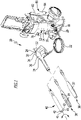
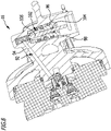
- FIG 1 shows a perspective view of an advantageous embodiment of a high-pressure cleaning device according to the invention, which is given the reference number 10 .
- the high-pressure cleaning device 10 includes a motor pump unit 12 , shown only schematically, which includes a drive motor 14 and a high-pressure pump 16 .
- the high-pressure pump 16 is flanged to the drive motor 14 .
- the high-pressure pump 16 has a pump inlet 18 to which a feed line for liquid to be pressurized, in particular water, can be connected. Furthermore, the high-pressure pump 16 has a pump outlet 20 to which a high-pressure line 22, in this case a high-pressure hose, for pressurized liquid can be connected.
- a control unit 24 of the high-pressure cleaning device 10, designed as a high-pressure pistol 26, is connected to the high-pressure line 22.
- An input unit 28 is arranged on the high-pressure gun 26 and includes input elements for actuation by an operator.
- the input elements have a "+" button 30 and a "-" button 32 .
- the high-pressure gun 26 also has a display unit 34 .
- the display unit 34 is adjacent to the input unit 28, for example.
- the input unit 28 and the display unit 34 could also be integrated into one another and designed as a touch screen, for example.
- the display unit 34 includes an optical image display and forms an information unit of the high-pressure cleaning device 10. Information can be displayed visually on the display unit 34.
- the high-pressure cleaning device 10 has a discharge unit 36 in the form of a low-pressure cleaning agent nozzle 37 .
- the high-pressure cleaning device 10 also includes a discharge unit 38 in the form of a high-pressure nozzle 39.
- the high-pressure cleaning device 10 can also have a discharge device 40, which includes a plurality of discharge units.
- a discharge unit 41 is provided, configured as a low-pressure detergent nozzle 42, and a discharge unit 43, configured as a high-pressure nozzle 44.
- the operator can connect the dispensing unit 36, the dispensing unit 38 or the dispensing device 40 to the high-pressure gun 26 and bring it into fluid communication with it.
- the operator can select either the low-pressure cleaning agent nozzle 42 or the high-pressure nozzle 44 and thereby bring it into fluid communication with the high-pressure line 22 .
- a different cross-section is provided on the output side through which the pressurized liquid escapes.
- cleaning liquid emerges under high pressure with a small cross-sectional area and a rather low volume flow.
- the low-pressure cleaning agent nozzles 37 and 42 have a significantly larger opening cross section, and liquid emerges with a high volume flow and under rather low pressure.
- the operator influences the pressure at the outlet of the respective nozzle during operation of the high-pressure cleaning device 10 with the operating unit 24 actuated. This also influences the pressure in the high-pressure line 22 and on the outlet side of the high-pressure pump 16.
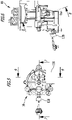
- the high-pressure pump 16 is designed as a piston pump and in particular as an axial piston pump.
- the high-pressure pump 16 includes a base body 46 in which a plurality of axial pistons (an axial piston 48 shown) are mounted so as to be linearly displaceable.
- the drive motor 14 includes a swash plate, not shown in the drawing, whose rotation moves the axial pistons 48 .
- the high-pressure pump 16 has a suction chamber 50 which is flow-connected to the pump inlet 18 or forms this.
- the suction chamber 50 opens into a pump chamber 52, between which a suction valve 54 is connected. Liquid that is sucked in can enter the pump chamber 52 and is pressurized therein by the axial pistons 48 .
- the pump chamber 52 opens into a pressure chamber 56, with a pressure valve 58 being connected between these.
- the pressure space 56 is divided into a first space 60 and a second space 62 . Liquid flowing out of the pump space 52 enters the first space 60 . Between the space areas 60, 62 is a Check valve 64 used. During operation of the high-pressure pump 16, the check valve 64 can assume an open position, and liquid flows through the chambers 60 and 62 to the pump outlet 20.
- the pump outlet 20 is formed by the pressure chamber 56 on the outlet side or is in flow communication with it.
- An advantageous embodiment of the high-pressure pump like the high-pressure pump 16, includes a so-called overflow with an overflow valve arranged therein.
- an overflow valve arranged therein.
- a control line 66 opens into the pressure chamber 56 at the second space area 62.
- the control line 66 can also be referred to as a control channel.
- Liquid in the pressure chamber 56 can thereby apply pressure to the overflow valve 68 of an overflow valve 70 . If the high-pressure pistol 26 is no longer actuated while the high-pressure cleaning device 10 is in operation, this leads to a pressure surge via the high-pressure line 22 into the pressure chamber 56. In a manner known per se, the pressure surge via the control line 66 leads to the overflow valve 68 being acted upon leads to the overflow valve 68 opening and a valve tappet 72 of the overflow 70 being displaced.
- the valve tappet 72 can actuate a switching element, not shown in the drawing, for example a microswitch.
- the switching element is connected to a control unit 76 of the high-pressure pump 16 via a signal line 74 .
- the switching element can be operatively connected directly to the drive motor 14 . If a switching signal is present, the control unit 76 can switch off the drive motor 14 via a control line 78 (or the switching element), so that the drive of the high-pressure pump 16 is disabled if the high-pressure gun 26 is not actuated. If the high-pressure gun 26 is actuated again, the drive motor 14 is activated again.
- the high-pressure cleaning device 10 comprises an admixing device 80 in order to admix a cleaning chemical to the pressurized liquid.
- the addition of cleaning chemicals is intended for operation with the low-pressure cleaning agent nozzles 37 and 42.
- the admixing device 80 on the high-pressure cleaning device 10 includes a receptacle 82 for a container 84 in which the cleaning chemical is stored.
- the receptacle 82 is in flow connection with the pressure chamber 56 via a supply line 86 which is partially enclosed by the base body 46 .
- the control line 66 preferably forms a section of the feed line 86.
- a check valve 88 is connected in the feed line 86, for example near the overflow 70.
- the feed line 86 can also be referred to as a feed channel.
- the admixing device 80 also includes an injector 90, which is designed here as a Venturi injector.
- the injector 90 is arranged in the pressure chamber 56, in particular in the second spatial area 62.
- the feed line 86 opens in the second spatial area 62 into the suction side of the injector 90.
- the liquid pressure in the supply line 86 drops so far due to the suction effect of the injector 90 that the check valve 88 opens.
- the pressure in the feed line 86 is below the ambient pressure of the atmosphere (approximately less than 1 bar).
- the cleaning chemical can flow into the injector 90 via the supply line 86 due to the suction effect of the injector 90 and is admixed with the liquid.
- the mixture of liquid and cleaning chemical flows to the low-pressure cleaning agent nozzle 37, 42 and can be discharged through this.
- the high-pressure nozzle 39 or 44 is connected to the high-pressure gun 26, the pressure in the high-pressure line 22 and thus in the pressure chamber 56 is so high that the suction effect of the injector 90 is eliminated.
- the pressure in the supply line 86 is also high, the check valve 88 remains closed and no cleaning chemical is drawn in.
- the high-pressure cleaning device 10 By connecting or selecting a low-pressure cleaning agent nozzle 37, 42, the high-pressure cleaning device 10, and in particular the high-pressure pump 16, can be switched to a cleaning agent mode. Conversely, if the high-pressure nozzle 39 or 44 is connected or selected, the high-pressure cleaning device 10 and in particular the high-pressure pump 16 assumes a high-pressure mode.
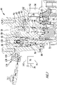
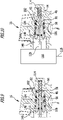
- the high-pressure pump 16 includes a return line 92 .
- the pressure chamber 56 is flow-connected to the suction chamber 50 via the return line 92 .
- the return line 92 has a first section formed in the base body 46, which opens into the pressure chamber 56 and in particular its first spatial region 60 ( figure 8 ).
- a second section 96 which forms a valve chamber 98 adjoins the first section 94 .
- a third section 100 adjoins the valve chamber 98 and opens into the suction chamber 50 ( figure 7 ).
- the second and third sections 96, 100 are also formed in the base body 46.
- the return line 92 can also be referred to as a return channel.
- the high-pressure pump 16 includes a valve unit 102 via which the free cross-sectional area of the return line 92 can be changed.
- the valve unit 102 comprises a valve body receiving part 104, which is inserted into the valve chamber 98, and a valve body 106.
- the valve body 106 is designed as a valve pin 108.
- the valve body receiving part 104 forms a valve seat 110 for the valve pin 108.
- the valve pin 108 can be in a closed position ( figures 9 and 11 ) on the valve seat 110 with a valve body sealing portion 112 sealingly or substantially sealingly.
- the return line 92 is closed.
- An elastic element in the form of a helical spring 104 acts on the valve pin 108 with a force directed towards its closed position.
- the high-pressure pump 16 includes a drive unit 116 which is assigned to the valve unit 102 .
- the drive unit 116 is designed in particular as an electric drive unit and is electrically connected to the control unit 76 via a control line 118 .
- the control unit 76 can control the drive unit 116 in order to move the valve pin 108 from the closed position into at least one open position and vice versa.
- the valve pin 108 can be displaced in the return line 92 and relative to the valve body receiving part 104 . The valve pin 108 is moved from the closed position into the at least one open position against the closing force of the helical spring 114.
- the drive unit 116 is shown in the drawing (in Figs figures 5 and 10 ) only shown schematically.
- the drive unit 116 includes a spindle drive.
- the spindle drive can move a tappet 120 linearly, which is coupled to the valve pin 108 and, for example, is firmly connected to it.
- the tappet 120 is arranged on the side of the valve pin 108 facing away from the helical spring 114 .
- the drive unit 116 can have a retaining projection 146 which engages in the base body 46 .
- the valve unit 102 can be held in the valve chamber 98 via the holding projection 146 .
- the retaining projection 146 is inserted into the valve body 46 with a force fit and/or a form fit.
- the valve unit 102 can be supported on the retaining projection 146 against the pressure in the return line 92 acting on it.
- a sealing element 148 can preferably be supported via the holding projection 146 .
- the sealing element 148 seals between the valve chamber 98 and the retaining projection 146.
- the sealing element 148 is designed as an O-ring surrounding the valve pin 108.
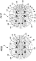
- the valve body sealing section 112 is formed, for example, on an annular collar 122 on which the coil spring 114 is supported on the opposite side.
- valve pin 108 Starting from the valve body sealing section 112, the valve pin 108 initially comprises a first, cylindrical section 124 and then a second, conical section 126.
- the cylindrical section 124 is dimensioned such that the valve pin 108 is arranged in the valve body receiving part 104 with some play. If the valve pin 108 lifts off the valve seat 110, liquid can flow through the return line 92.
- the conical section 126 is designed to taper conically, in particular the valve pin 108 is doubly conically tapered.
- the taper increases with increasing distance from the valve body sealing section 112 .
- this can be understood in particular to mean that the change in the diameter and thus in the cross section of the valve pin 108 increases per adjustment path or length section of the valve pin 108 .
- the valve pin 108 In the opposite direction to the direction for transferring the valve pin 108 from the closed position into the at least one open position, the valve pin 108 therefore has a taper which increases with increasing distance from the valve body sealing section 112 .
- this makes it possible, in the at least one open position, to make the change in the free cross-sectional area of return line 92 on valve seat 110 per adjustment path of valve pin 108 relative to valve seat 110 dependent on the position of valve pin 108 relative to valve seat 110.
- the change in the free cross-sectional area due to the increasing tapering of the valve pin 108 increases as the distance between the valve body sealing section 112 and the valve seat 110 increases.
- a further cylindrical section 128 of the valve pin 108 whose diameter is smaller than that of the cylindrical section 124.
- the sealing element 148 surrounds the cylindrical section 124.
- the liquid flows through the return line 92 axially past the valve seat 110 (in the longitudinal direction of the valve pin 108) and then downstream of the valve seat 110 radially away from the valve pin 108.
- the return line 92 is therefore aligned radially downstream of the valve seat 110 with respect to the longitudinal direction of the valve pin 108 .
- a passage 130 into the third section 100 is formed in the valve body receiving part 104 .
- a pressure valve 132 is provided in the return line 92 downstream of the valve unit 102 .
- the pressure valve 132 is designed as a valve ring 134, in particular as an O-ring.
- the valve ring 134 surrounds the valve body receiving part 104 and can close the passage 130 and thus the return line 92 in a sealing or substantially sealing manner. If the pressure in the return line 92 exceeds a threshold pressure, the pressure valve 132 opens. If the pressure is below a threshold pressure, the return line 92 is closed.
- the purpose of the pressure valve 132 is that when the high-pressure pump 16 is started up, suction operation (liquid is sucked in at the pump inlet 18 which is not connected to a pressure line) can be carried out, even if the valve pin 108 is in an open position. In this case, the pressure valve 132 prevents air from being sucked in via the return line 92 .
- the high-pressure pump 16 also includes a detection unit 136.
- the detection unit 136 can be used to detect when a fluid pressure on the pressure side of the pump chamber 52 falls below a threshold pressure. In addition, the detection unit 136 can be used to detect when a threshold pressure is exceeded.
- the detection unit 136 includes a pressure sensor 138 or is designed as such, with which the liquid pressure can be measured.
- the pressure sensor 138 is arranged on the high-pressure pump 116 in such a way that a liquid pressure in the feed line 86 which opens into the pressure chamber 56 can be detected.
- the pressure in the supply line 86 is related to the pump pressure of the high-pressure pump 16 which is present at the pump outlet 20 . By detecting the fluid pressure in the supply line 86 at the pressure chamber 56, the pump pressure can also be inferred.
- the pressure sensor 138 is connected, for example, to a measuring line 140 which is an extension of the control line 66 .
- the pressure sensor 138 is connected to the control unit via a signal line 142 in order to provide it with a signal corresponding to the liquid pressure.
- the measuring line 140 can also be referred to as a measuring channel.
- a high-pressure mode is provided on the one hand and a detergent mode on the other.
- the fluid pressure that can be detected by the pressure sensor 108 in the pressure chamber 56 is regulated.
- the valve unit 102 is activated in order to control the volume flow of the liquid to be dispensed and thus to control the dosing of the cleaning chemical.
- a high-pressure nozzle 39 or 44 is connected or selected, there is pressure in the pressure chamber 56 and thus also in the supply line when the operating unit 24 is actuated 86 a high pressure.
- the operator uses the "+" 30 and "-" 32 keys to specify a pressure level. Each pressure step corresponds to a pump pressure at the pump outlet 20 and thus to a fluid pressure in the supply line 86 related to this.
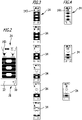
- figure 3 shows, by way of example, the display unit 34 in the high-pressure mode in various pressure stages which decrease from top to bottom. A total of six different pressure levels are provided, which the operator can select using buttons 30 and 32 . Pressing the "+" button 30 increases the pressure and pressing the "-" button 32 decreases the pressure.
- the specification of the operator is wirelessly transmitted from the input unit 28 to the control unit 76 coupled to it.
- the control unit 76 actuates the drive unit 116.
- the liquid pressure which is detected by the pressure sensor 138, is regulated by actuating the drive unit 116.
- the high-pressure cleaning device 10 and in particular the high-pressure pump 16 assumes a control mode.
- the controller 76 may determine that the high pressure mode has been entered by the pressure sensor 138 detecting a fluid pressure in the supply line 86 that is above a threshold pressure.
- a symbol 143 of a high-pressure nozzle for example, is displayed on the display unit 34 . Also displayed is information that is associated with the specification by the operator. These are representations of the pressure levels symbolized by black lines or bars.
- Information for changing the display unit 34 can be transmitted wirelessly from the control unit 76 to the display unit 34 coupled to it.
- the return line 92 is closed, for example, and the valve body sealing section 112 is in sealing contact with the valve seat 110 ( figures 9 and 11 ).
- the position of the valve unit 112 is changed in that the valve pin 118 is transferred to an open position.
- This increases the free cross-sectional area of the return line 92, liquid flows from the pressure chamber 56 to the suction chamber 50, and the pump pressure at the pump outlet 20 is reduced. This is detected via the pressure in the feed line 86 .
- the pressure in the feed line 86 is regulated by controlling the drive unit 116 .
- valve pin 108 being transferred to an open position, depending on the pressure level, in which the free cross-sectional area of return line 92 increases further, the volume flow through return line 92 is increased and the pump pressure at pump outlet 20 is reduced.
- the liquid pressure is regulated in the respective pressure stage.
- valve pin 108 If the valve pin 108 is moved into an open position, the pressure valve 132 opens so that a flow through the return line 92 is released.
- valve pin 108 In the control mode, the valve pin 108 is not pushed by the drive unit 116 by the entire possible adjustment path to implement the lowest pressure level.
- the valve pin 108 is displaced, for example, only to the extent of the conical section 126 following the cylindrical section 124 to the extent that the conicity of the section 126 does not change. This corresponds to the range of constant tapering of the conical section 126 and a change in the free cross-sectional area of the return line 92 per adjustment path, which is constant.
- the control unit 76 analyzes the signal from the pressure sensor 138 and can determine that the detergent nozzle 37 or 42 is being used. The control unit 76 switches to a detergent mode. An indication of this is transmitted wirelessly to the display unit 34 . In particular, an icon 144 for a low pressure detergent nozzle is shown.
- the display unit 34 changes the image display from that in figure 3 shown high-pressure mode in the in figure 4 detergent mode shown.
- the high-pressure cleaning device 10 and in particular the high-pressure pump 16 assumes a non-regulating mode.
- the fluid pressure sensed by pressure sensor 138 is no longer regulated.
- the operator controls the position of the valve unit 102 using the "+" 30 and "-" 32 keys. This has the particular consequence that the free cross-sectional area of the return line 92 and the volume flow through it are controlled by the operator.
- valve unit 102 opens and the volume flow at the pump outlet 20 changes due to the increasing volume flow through the return line 92. Since the cleaning chemical is sucked into the injector 90 via the supply line 86 at the same time, the mixing ratio between the liquid and the cleaning chemical changes.
- FIG. 1 shows the respective image display of the display unit 34 in this regard. Different mixing ratios are symbolized, for example, by a different number of lines or bars. up in figure 4 the situation of maximum dosing of the cleaning chemical is shown, ie a high mixing ratio of the cleaning chemical with the liquid (high percentage of cleaning chemical). The mixing ratio of the cleaning chemical decreases downwards.
- the image display of the display unit 34 is at least partially "inverted" in the high-pressure mode and in the detergent mode. While in the high-pressure mode the pressure levels are symbolized by bars with spaces between them, in the detergent mode bars displayed in these spaces symbolize the mixing ratio of the cleaning chemical with the liquid.
- the user specification on the keys 30 and 32 is implemented by the control unit 76 to control the drive unit 116 .
- the drive unit 116 moves the valve pin 108 to such an extent that the free cross-sectional area of the return line 92 is changed depending on the selected dosage of cleaning chemicals (mixing ratio).
- the representation on the display unit 34 for the pressure stage on the one hand ( 3 ) and the mixing ratio on the other hand ( 4 ) reflects opposite positions of the valve assembly 102 and associated free cross-sectional areas of the return line 92.
- the valve unit 102 In the high-pressure mode, the valve unit 102 is at high pressure stage (above in 3 ) closed, at low pressure level (below in 3 ) open.
- detergent mode on the other hand, at high levels of detergent chemical (above in 4 ) more open than required at low levels of detergent chemical (below in 4 ) the case is.
- valve pin 108 is displaced in the detergent mode to such an extent that the change in the free cross-sectional area takes place via the increasing narrowing of the conical section 126 .
- the free cross-sectional area therefore changes to a greater extent per adjustment path of the valve body 106 than is the case per adjustment path in the high-pressure mode.
- the pressure sensor 138 again detects that the pressure in the supply line 86 again exceeds the first-mentioned threshold pressure.
- the high-pressure cleaning device 10 switches to the high-pressure mode already explained.
- the threshold pressures above which the high-pressure mode and below which the detergent mode is detected can preferably be identical.
- the geometry of the valve pin 108 which in particular has a double-conical section 126, makes it possible to reliably ensure the different setting of the pressure stages and the regulation of the fluid pressure in the high-pressure mode.
- the geometry of the volume flow of the liquid through the return line 92 and thus the mixing ratio of the cleaning chemical with the liquid can be reliably adjusted. Therefore, the division of the "control band" for the high pressure mode and the "control band” of the valve pin 108 allows reliable operation of the high pressure pump 16 in both the modulating and non-modulating modes.
- the high-pressure cleaning device 10 and the high-pressure pump 16 make it possible, depending on the respectively selected or connected discharge unit, to switch to regulating the liquid pressure or controlling the dosage (mixing ratio) of the cleaning chemical.
- the input unit 28 for selecting the pressure stage or for selecting the mixing ratio is identical.
- the display unit 34 shows the pressure levels or the levels for the mixing ratio.
- the high-pressure cleaning device 10 is therefore also characterized by particularly user-friendly and intuitive operation.
- the high-pressure pump has a valve 150 via which the dosage of the cleaning chemical and thus the mixing ratio with the liquid can be influenced.
- a metering valve 150 is connected, for example, in the feed line 86 .
- figure 7 shows an example of the arrangement of the metering valve 150, preferably upstream of the check valve 88 in the direction of flow of the cleaning chemical.
- the metering valve 150 may be manually operable or adjustable. It is also conceivable for metering valve 150 to be actuated by control unit 76 as a function of the operator's specification on input unit 28.
- the liquid pressure is preferably only regulated in the high-pressure mode when the drive motor 14 is in operation. This can be determined by the control unit 76, for example. This can prevent unnecessary pressure regulation from taking place when the drive motor 14 is switched off and the fluid pressure detected by the pressure sensor 138 changes as a result.
- the operating mode is switched between the high-pressure mode and the cleaning agent mode and vice versa, preferably only when the drive motor 14 is in operation, as is the operating mode-dependent content of the display unit 34.
Abstract
Die Erfindung betrifft ein Hochdruckreinigungsgerät (10) mit einer Hochdruckpumpe (16), die einen Saugraum (50) umfasst, mindestens einen diesem nachgelagerten Pumpraum (52), in dem Flüssigkeit unter Druck gesetzt wird, und einen dem Pumpraum (52) nachgelagerten Druckraum (56). Um ein derartiges Hochdruckreinigungsgerät bereitzustellen, das einen zuverlässigeren Betrieb ermöglicht, wird erfindungsgemäß vorgeschlagen, dass die Hochdruckpumpe (16) eine Rückführleitung (92) umfasst, über die der Druckraum (56) mit dem Saugraum (50) in Strömungsverbindung steht und eine Ventileinheit (102), mit der eine freie Querschnittsfläche der Rückführleitung (92) veränderbar ist, dass das Hochdruckreinigungsgerät (10) eine der Ventileinheit (102) zugeordnete Antriebseinheit (116), eine mit der Antriebseinheit (116) gekoppelte Steuereinheit (76) und einen mit der Steuereinheit (76) gekoppelten Drucksensor (138) umfasst, mit dem ein Flüssigkeitsdruck druckseitig des Pumpraumes (52) erfassbar ist, und dass der Flüssigkeitsdruck abhängig vom Signal des Drucksensors (138) auf einen vorgegebenen oder vorgebbaren Flüssigkeitsdruck unter Veränderung der freien Querschnittsfläche der Rückführleitung (92) regelbar ist.The invention relates to a high-pressure cleaning device (10) with a high-pressure pump (16), which comprises a suction chamber (50), at least one pump chamber (52) downstream of this, in which liquid is pressurized, and a pressure chamber ( 56). In order to provide such a high-pressure cleaning device that enables more reliable operation, it is proposed according to the invention that the high-pressure pump (16) comprises a return line (92) via which the pressure chamber (56) is in flow communication with the suction chamber (50) and a valve unit (102 ), with which a free cross-sectional area of the return line (92) can be changed, that the high-pressure cleaning device (10) has a drive unit (116) assigned to the valve unit (102), a control unit (76) coupled to the drive unit (116) and a control unit connected to the control unit (76) coupled pressure sensor (138), with which a fluid pressure on the pressure side of the pump chamber (52) can be detected, and that the fluid pressure depends on the signal from the pressure sensor (138) to a predetermined or predeterminable fluid pressure while changing the free cross-sectional area of the return line (92 ) is adjustable.
Description
Die Erfindung betrifft ein Hochdruckreinigungsgerät mit einer Hochdruckpumpe, die einen Saugraum umfasst, mindestens einen diesem nachgelagerten Pumpraum, in dem Flüssigkeit unter Druck gesetzt wird, und einen dem Pumpraum nachgelagerten Druckraum.The invention relates to a high-pressure cleaning device with a high-pressure pump, which comprises a suction chamber, at least one pump chamber downstream of this, in which liquid is pressurized, and a pressure chamber downstream of the pump chamber.
Eine Hochdruckpumpe des Hochdruckreinigungsgerätes der eingangs genannten Art ist beispielsweise als Kolbenpumpe ausgestaltet, insbesondere als Axialkolbenpumpe, und umfasst üblicherweise zwei oder mehr hin- und herbewegbare Kolben. Unter Bewegung der Kolben wird aus dem Saugraum eingesaugte Flüssigkeit im Pumpraum unter Druck gesetzt und über den Druckraum von der Hochdruckpumpe abgegeben. Mit dem Saugraum steht eine Saugleitung in Strömungsverbindung, und der Druckraum steht mit einer Hochdruckleitung in Strömungsverbindung, insbesondere einem Hochdruckschlauch, und über diese mit einer Austragsvorrichtung des Hochdruckreinigungsgerätes.A high-pressure pump of the high-pressure cleaning device of the type mentioned at the outset is designed, for example, as a piston pump, in particular as an axial piston pump, and usually comprises two or more pistons that can be moved back and forth. When the pistons move, liquid sucked in from the suction chamber is pressurized in the pump chamber and discharged via the pressure chamber by the high-pressure pump. A suction line is in flow connection with the suction chamber, and the pressure chamber is in flow connection with a high-pressure line, in particular a high-pressure hose, and via this with a discharge device of the high-pressure cleaning device.
Aufgabe der vorliegenden Erfindung ist es, ein gattungsgemäßes Hochdruckreinigungsgerät bereitzustellen, das einen zuverlässigeren Betrieb ermöglicht.The object of the present invention is to provide a generic high-pressure cleaning device that enables more reliable operation.
Diese Aufgabe wird bei einem Hochdruckreinigungsgerät der eingangs genannten Art erfindungsgemäß dadurch gelöst, dass die Hochdruckpumpe eine Rückführleitung umfasst, über die der Druckraum mit dem Saugraum in Strömungsverbindung steht und eine Ventileinheit, mit der eine freie Querschnittsfläche der Rückführleitung veränderbar ist, dass das Hochdruckreinigungsgerät eine der Ventileinheit zugeordnete Antriebseinheit, eine mit der Antriebseinheit gekoppelte Steuereinheit und einen mit der Steuereinheit gekoppelten Drucksensor umfasst, mit dem ein Flüssigkeitsdruck druckseitig des Pumpraumes erfassbar ist, und dass der Flüssigkeitsdruck abhängig vom Signal des Drucksensors auf einen vorgegebenen oder vorgebbaren Flüssigkeitsdruck unter Veränderung der freien Querschnittsfläche der Rückführleitung regelbar ist.In a high-pressure cleaning device of the type mentioned at the outset, this object is achieved according to the invention in that the high-pressure pump comprises a return line, via which the pressure chamber is in flow connection with the suction chamber, and a valve unit, with which a free cross-sectional area of the return line can be changed, that the high-pressure cleaning device has one of the valve unit, a control unit coupled to the drive unit and a pressure sensor coupled to the control unit, with which a liquid pressure on the pressure side of the pump chamber can be detected, and that the liquid pressure depends on the signal from the pressure sensor to a predetermined or predeterminable liquid pressure, changing the free cross-sectional area of the Return line is adjustable.
Bei dem erfindungsgemäßen Hochdruckreinigungsgerät ist die Möglichkeit gegeben, einen Flüssigkeitsdruck druckseitig des Pumpraumes zu regeln. Zu diesem Zweck umfasst die Hochdruckpumpe unter anderem eine Rückführleitung vom Druckraum zum Saugraum, an der die Ventileinheit angeordnet ist oder in welche die Ventileinheit geschaltet ist. Die Steuereinheit kann die Antriebseinheit zur Betätigung der Ventileinheit ansteuern, wodurch die freie Querschnittsfläche der Rückführleitung verändert werden kann. Der Drucksensor führt der Steuereinheit ein Signal zu, das eine Information über den gemessenen Flüssigkeitsdruck druckseitig des Pumpraumes umfasst. Durch Vergleich des gemessenen mit dem vorgegebenen oder vorgebbaren Flüssigkeitsdruck steuert die Steuereinheit die Antriebseinheit zur Veränderung der freien Querschnittsfläche der Rückführleitung an. Flüssigkeit kann abhängig von der Stellung der Ventileinheit und damit verbundener unterschiedlich großer freier Querschnittsfläche vom Druckraum zum Saugraum strömen und zieht eine Änderung des Flüssigkeitsdruckes nach sich, der mit dem Drucksensor druckseitig des Pumpraumes gemessen werden kann. In der Praxis zeigt sich, dass durch die erfindungsgemäße Lösung eine zuverlässige Regelung bei zugleich konstruktiv einfacher Ausgestaltung der Hochdruckpumpe erzielt werden kann.With the high-pressure cleaning device according to the invention, there is the possibility of regulating a liquid pressure on the pressure side of the pump chamber. For this purpose, the high-pressure pump includes, among other things, a return line from the pressure chamber to the suction chamber, on which the valve unit is arranged or into which the valve unit is connected. The control unit can control the drive unit to actuate the valve unit, as a result of which the free cross-sectional area of the return line can be changed. The pressure sensor supplies the control unit with a signal that includes information about the measured liquid pressure on the pressure side of the pump chamber. By comparing the measured fluid pressure with the predetermined or predeterminable fluid pressure, the control unit controls the drive unit to change the free cross-sectional area of the return line. Depending on the position of the valve unit and the associated free cross-sectional area of different sizes, liquid can flow from the pressure chamber to the suction chamber and entails a change in the liquid pressure, which can be measured with the pressure sensor on the pressure side of the pump chamber. In practice, it has been shown that the solution according to the invention can be used to achieve reliable regulation while at the same time having a structurally simple configuration of the high-pressure pump.
Unter "Stellung der Ventileinheit" wird vorliegend insbesondere die Stellung eines Ventilkörpers relativ zu einem Ventilsitz der Ventileinheit verstanden, wobei abhängig von der Relativstellung eine unterschiedlich große freie Querschnittsfläche der Rückführleitung freigegeben ist und die Menge der die Rückführleitung durchströmenden Flüssigkeit eingestellt werden kann.The term "position of the valve unit" is used here in particular to mean the position of a valve body relative to a valve seat of the valve unit, with a different size of free cross-sectional area of the return line being released depending on the relative position and the amount of liquid flowing through the return line being able to be adjusted.
Unter "druckseitig des Pumpraumes" wird vorliegend insbesondere verstanden, dass der Flüssigkeitsdruck am oder in einem Raum oder einer Flüssigkeitsleitung erfassbar ist, der bzw. die einem den Pumraum vom Druckraum trennenden Druckventil nachgeordnet sind. Hierunter kann insbesondere auch eine an den Druckraum angeschlossene oder in diesen mündende Flüssigkeitsleitung verstanden werden.“On the pressure side of the pump chamber” is understood here in particular to mean that the liquid pressure can be detected on or in a chamber or a liquid line which is/are arranged downstream of a pressure valve separating the pump chamber from the pressure chamber. This can in particular also be understood to mean a liquid line connected to the pressure chamber or opening into it.
Günstig ist es, wenn mit dem Drucksensor der Flüssigkeitsdruck in der Hochdruckpumpe erfassbar ist.It is favorable if the liquid pressure in the high-pressure pump can be detected with the pressure sensor.
Vorzugsweise ist mit dem Drucksensor ein Flüssigkeitsdruck am oder im Druckraum erfassbar. Beispielsweise ist der Drucksensor zu diesem Zweck am Druckraum angeordnet oder an einer in diesen mündenden Flüssigkeitsleitung.A liquid pressure on or in the pressure chamber can preferably be detected with the pressure sensor. For example, the pressure sensor is arranged for this purpose on the pressure chamber or on a liquid line opening into it.
Bei dem mit dem Drucksensor erfassbaren Flüssigkeitsdruck kann es sich beispielsweise um den Pumpendruck der Flüssigkeit handeln, wie er an einem Pumpenausgang der Hochdruckpumpe vorliegt, an welchen Ausgang die Hochdruckleitung angeschlossen oder anschließbar ist. Der Flüssigkeitsdruck kann auch ein mit dem Pumpendruck gekoppelter Druck sein, so dass dieser über eine bekannte Beziehung des Flüssigkeitsdruckes mit dem Pumpendruck durch eine Messung des Flüssigkeitsdruckes ermittelt werden kann.The liquid pressure that can be detected by the pressure sensor can be, for example, the pump pressure of the liquid as it is present at a pump outlet of the high-pressure pump, to which outlet the high-pressure line is connected or can be connected. Fluid pressure may also be a pressure coupled to pump pressure so that it can be determined from a known relationship of fluid pressure to pump pressure by measuring fluid pressure.
Der Pumpenausgang ist beispielsweise am Druckraum angeordnet oder steht mit diesem in Strömungsverbindung.The pump outlet is arranged, for example, on the pressure chamber or is in flow connection with it.
Der Flüssigkeitsdruck ist der Steuereinheit beispielsweise über eine Eingabeeinheit des Hochdruckreinigungsgerätes vorgebbar. Dabei kann vorgesehen sein, dass der Flüssigkeitsdruck als Absolutwert und/oder als Relativwert, insbesondere über eine Druckstufe, vorgegeben werden kann.The liquid pressure can be specified for the control unit, for example via an input unit of the high-pressure cleaning device. It can be provided that the liquid pressure can be specified as an absolute value and/or as a relative value, in particular via a pressure step.
Vorzugsweise ist der Flüssigkeitsdruck der Steuereinheit stufenweise vorgebbar, zum Beispiel über die vorstehend erwähnte Druckstufe.The liquid pressure of the control unit can preferably be predetermined in stages, for example via the pressure stage mentioned above.
Alternativ oder ergänzend kann vorgesehen sein, dass der Flüssigkeitsdruck der Steuereinheit kontinuierlich vorgebbar ist.Alternatively or in addition, it can be provided that the liquid pressure of the control unit can be specified continuously.
Die freie Querschnittsfläche der Rückführleitung ist zum Regeln des Flüssigkeitsdruckes bevorzugt stufenweise veränderbar. Beispielsweise kann vorgesehen sein, dass die Ventileinheit diskrete Stellungen einnehmen kann.The free cross-sectional area of the return line can preferably be changed in steps to regulate the liquid pressure. For example, it can be provided that the valve unit can assume discrete positions.
Alternativ oder ergänzend ist es günstig, wenn die freie Querschnittsfläche der Rückführleitung zum Regeln des Flüssigkeitsdruckes kontinuierlich veränderbar ist. Die Ventilstellung der Ventileinheit kann zum Beispiel kontinuierlich verändert werden.Alternatively or in addition, it is favorable if the free cross-sectional area of the return line can be continuously changed to regulate the liquid pressure. The valve position of the valve unit can be changed continuously, for example.
Vorzugsweise umfasst die Ventileinheit einen Ventilkörper, mit dem die Antriebseinheit gekoppelt ist, und einen Ventilsitz, an dem der Ventilkörper in einer Schließstellung dichtend oder im Wesentlichen dichtend anliegt und von dem der Ventilkörper in mindestens eine Offenstellung zur Änderung der freien Querschnittsfläche der Rückführleitung anhebbar ist. In der Schließstellung ist die Rückführleitung zum Beispiel verschlossen und der Pumpendruck maximal. Durch Anheben des Ventilkörpers vom Ventilsitz kann die freie Querschnittsfläche der Rückführleitung vergrößert, die Menge der die Rückführleitung durchströmenden Flüssigkeit vergrößert und der Pumpendruck verringert werden.The valve unit preferably comprises a valve body to which the drive unit is coupled, and a valve seat against which the valve body bears in a sealing or substantially sealing manner in a closed position and from which the valve body can be raised into at least one open position in order to change the free cross-sectional area of the return line. In the closed position, the return line is closed, for example, and the pump pressure is maximum. By raising the valve body from the valve seat, the free cross-sectional area of the return line can be increased, the quantity of liquid flowing through the return line increased and the pump pressure reduced.
Es kann vorgesehen sein, dass der Ventilkörper entgegen der Wirkung eines elastischen Rückstellelementes von der Schließstellung in die mindestens eine Offenstellung überführbar ist. Das Rückstellelement ist zum Beispiel eine Druckfeder, die den Ventilkörper in Richtung auf die Schließstellung mit einer Schließkraft beaufschlagt.It can be provided that the valve body can be transferred from the closed position into the at least one open position counter to the action of an elastic restoring element. The restoring element is a compression spring, for example, which applies a closing force to the valve body in the direction of the closed position.
Als vorteilhaft erweist es sich, wenn in der mindestens einen Offenstellung die Änderung der freien Querschnittsfläche am Ventilsitz pro Verstellweg des Ventilkörpers relativ zum Ventilsitz abhängig ist von der Position des Ventilkörpers relativ zum Ventilsitz. Dadurch lässt sich insbesondere eine nicht-konstante Kennlinie der Ventileinheit umsetzen. Je nachdem, welche Relativstellung der Ventilkörper und der Ventilsitz einnehmen, wird die freie Querschnittsfläche pro Verstellweg in größerem oder weniger großem Ausmaß verändert. Dies ist zum Beispiel günstig, um unterschiedliche Charakteristika der Ventileinheit für unterschiedliche Einsatzzwecke der Hochdruckpumpe bereitzustellen. Beispielsweise kann vorgesehen sein, dass sich die freie Querschnittsfläche im Bereich einer Stellung der Ventileinheit nur in geringem Umfang ändert, wenn der Ventilkörper relativ zum Ventilsitz bewegt wird. Dies kann zur Regelung unterschiedlicher vorgebbarer Flüssigkeitsdrücke vorgesehen sein. In einem andersartigen Bereich der Relativstellung von Ventilkörper und Ventilsitz kann vorgesehen sein, dass sich bei der Relativbewegung eine größere Änderung der Querschnittsfläche ergibt. Dies kann zu einer größeren Änderung des Volumenstroms durch die Rückführleitung eingesetzt werden und mit einem Betriebsmodus der Hochdruckpumpe verknüpft sein, in dem der Flüssigkeitsdruck nicht mehr geregelt wird, über die Änderung des Volumenstroms jedoch eine Konzentration einer der Flüssigkeit beimischbaren Reinigungschemikalie am Pumpenausgang verändert wird. Darauf wird nachfolgend noch eingegangen.It has proven to be advantageous if in the at least one open position the change in the free cross-sectional area on the valve seat per adjustment path of the valve body relative to the valve seat is dependent on the position of the valve body relative to the valve seat. In this way, in particular, a non-constant characteristic curve of the valve unit can be implemented. Depending on the relative position of the valve body and the valve seat, the free cross-sectional area per adjustment path is changed to a greater or lesser extent. This is favorable, for example, in order to provide different characteristics of the valve unit for different uses of the high-pressure pump. For example, it can be provided that the free cross-sectional area changes only to a small extent in the region of a position of the valve unit if the valve body is moved relative to the valve seat. This can be provided for controlling different predeterminable liquid pressures. In a different area of the relative position of the valve body and the valve seat, it can be provided that the relative movement results in a greater change in the cross-sectional area. This can be used for a larger change in the volume flow through the return line and be linked to an operating mode of the high-pressure pump in which the liquid pressure is no longer regulated, but the change in volume flow changes a concentration of a cleaning chemical that can be mixed with the liquid at the pump outlet. This will be discussed further below.
Als günstig erweist es sich, wenn die Rückführleitung strömungsabwärts des Ventilsitzes quer zur Längsrichtung des Ventilkörpers ausgerichtet ist. Beispielsweise strömt Flüssigkeit durch die Rückführleitung am Ventilsitz axial zu und diesem nachgelagert radial ab. Der Ventilkörper ist in diesem Fall zum Beispiel in eine von einem Ventilkörperaufnahmeteil gebildete Passung der Ventileinheit eingesetzt. Durch Vorsehen der Strömungsumlenkung von axialer in radiale Strömung kann eine feine Verstellung der freien Querschnittsfläche umgesetzt werden, was der Regelung des Flüssigkeitsdruckes, auch unterschiedlicher Flüssigkeitsdrücke, zugutekommt.It proves to be favorable if the return line is aligned downstream of the valve seat transversely to the longitudinal direction of the valve body. For example, liquid flows axially through the return line at the valve seat and radially downstream of this. In this case, the valve body is inserted, for example, into a fit of the valve unit formed by a valve body receiving part. By providing the flow deflection from axial to radial flow, a fine adjustment of the free cross-sectional area can be implemented, which benefits the regulation of the liquid pressure, including different liquid pressures.
Der Ventilkörper ist bei einer vorteilhaften Ausführungsform als Ventilstift ausgebildet, der in Längsrichtung in der Rückführleitung bewegbar und insbesondere verschiebbar ist.In an advantageous embodiment, the valve body is designed as a valve pin which can be moved and, in particular, displaced in the longitudinal direction in the return line.
Günstig ist es, wenn der Ventilstift, zumindest abschnittsweise und insbesondere in Gegenrichtung einer Richtung zur Überführung von der Schließstellung in die mindestens eine Offenstellung eine Verjüngung aufweist. Beispielsweise ist eine, zumindest abschnittsweise, konische Verjüngung vorgesehen.It is favorable if the valve pin has a taper, at least in sections and in particular in the opposite direction of a direction for transferring from the closed position into the at least one open position. For example, a conical taper, at least in sections, is provided.
Es kann vorgesehen sein, dass die Verjüngung zunimmt mit zunehmendem Abstand von einem in der Schließstellung am Ventilsitz anliegenden Ventilkörperdichtabschnitt des Ventilstiftes. Der Ventilstift weist angrenzend an den Ventilkörperdichtabschnitt zum Beispiel eine zylindrische oder im Wesentlichen zylindrische Kontur auf. Alternativ oder ergänzend, zum Beispiel in größerem Abstand vom Ventilkörperdichtabschnitt, kann am Ventilkörper eine Verjüngung vorgesehen sein. Mit zunehmendem Abstand kann die Verjüngung zunehmen. Darunter kann insbesondere verstanden werden, dass eine Änderung der Querschnittsfläche des Ventilkörpers pro Abstandsintervall vom Ventilkörperdichtabschnitt zunimmt. Bei einer Bewegung des Ventilstiftes relativ zum Ventilsitz kann dadurch die Änderung der freien Querschnittsfläche pro Verstellweg mit zunehmendem Abstand des Ventilkörperdichtabschnittes vom Ventilsitz zunehmen.Provision can be made for the taper to increase with increasing distance from a valve body sealing section which is in contact with the valve seat in the closed position of the valve pin. Adjacent to the valve body sealing section, the valve pin has, for example, a cylindrical or essentially cylindrical contour. Alternatively or additionally, for example at a greater distance from the valve body sealing section, a taper can be provided on the valve body. Taper may increase as distance increases. This can in particular be understood to mean that a change in the cross-sectional area of the valve body increases per distance interval from the valve body sealing section. When the valve pin moves relative to the valve seat, the change in the free cross-sectional area per adjustment path can increase as the distance between the valve body sealing section and the valve seat increases.
Die Antriebseinheit ist beispielsweise an der Hochdruckpumpe angeordnet. Es kann vorgesehen sein, dass die Antriebseinheit in einen in der Hochdruckpumpe gebildeten Ventilraum eingreift, in den die Ventileinheit eingesetzt ist. Die Antriebseinheit kann die Ventileinheit im Ventilraum abstützen und insbesondere dichtend an dieser anliegen, wodurch die Rückführleitung abgedichtet werden kann.The drive unit is arranged on the high-pressure pump, for example. Provision can be made for the drive unit to engage in a valve space formed in the high-pressure pump, into which the valve unit is inserted. The drive unit can support the valve unit in the valve chamber and, in particular, rest against it in a sealing manner, as a result of which the return line can be sealed.
Die Antriebseinheit kann auf vielfältige Weise ausgestaltet sein. Beispielsweise ist die Antriebseinheit eine elektrische, mechanische, hydraulische und/oder pneumatische Antriebseinheit.The drive unit can be configured in a variety of ways. For example, the drive unit is an electrical, mechanical, hydraulic and/or pneumatic drive unit.
Bei einer vorteilhaften Umsetzung der Hochdruckpumpe umfasst die Antriebseinheit einen Spindelantrieb. Unter Ansteuerung durch die Steuereinheit kann der elektrische Spindelantrieb betätigt und dadurch die Stellung der Ventileinheit verändert werden. Insbesondere wird der Ventilkörper relativ zum Ventilsitz verschoben. Zu diesem Zweck ist der Ventilkörper, insbesondere als Ventilstift ausgestaltet, beispielsweise fest mit dem Spindelantrieb gekoppelt.In an advantageous implementation of the high-pressure pump, the drive unit includes a spindle drive. The electric spindle drive can be actuated by the control unit, thereby changing the position of the valve unit. In particular, the valve body is displaced relative to the valve seat. For this purpose, the valve body, in particular designed as a valve pin, is, for example, firmly coupled to the spindle drive.
Von Vorteil ist es, wenn die Hochdruckpumpe strömungsabwärts der Ventileinheit an oder in der Rückführleitung ein Druckventil aufweist, das die Rückführleitung bei Überschreiten eines Schwellenwertdruckes freigibt und unterhalb des Schwellenwertdruckes dichtend oder im Wesentlichen dichtend verschließt. Über das Druckventil kann der Flüssigkeitsdruck in der Rückführleitung gehalten werden und die Rückführleitung erst freigegeben werden, wenn der Schwellenwertdruck überschritten ist. Durch das Druckventil kann beispielsweise vermieden werden, dass bei Inbetriebnahme der Hochdruckpumpe im Saugbetrieb Luft aus der Rückführleitung angesaugt wird, wenn der Ventilkörper eine Offenstellung einnimmt.It is advantageous if the high-pressure pump has a pressure valve downstream of the valve unit on or in the return line, which releases the return line when a threshold pressure is exceeded and below of the threshold pressure sealingly or substantially sealingly closed. The liquid pressure in the return line can be maintained via the pressure valve and the return line can only be released when the threshold pressure has been exceeded. The pressure valve can, for example, prevent air from being sucked in from the return line when the high-pressure pump is started up in suction mode when the valve body is in an open position.
Bevorzugt weist die Ventileinheit ein die Rückführleitung teilweise ausbildendes Ventilkörperaufnahmeteil auf und einen darin aufgenommenen Ventilkörper, und das Druckventil ist günstigerweise als das Ventilkörperaufnahmeteil umgebender Ventilring ausgestaltet. Das Ventilkörperaufnahmeteil ist beispielsweise in eine Bohrung eines Grundkörpers der Hochdruckpumpe eingesetzt und nimmt den Ventilkörper auf. Das Ventilkörperaufnahmeteil kann eine Austrittsöffnung aufweisen, die von dem es umgebenden Ventilring dichtend oder im Wesentlichen dichtend verschließbar ist. Der Ventilring ist zum Beispiel als O-Ring ausgestaltet.The valve unit preferably has a valve body receiving part that partially forms the return line and a valve body received therein, and the pressure valve is advantageously designed as a valve ring surrounding the valve body receiving part. The valve body receiving part is inserted, for example, into a bore in a base body of the high-pressure pump and receives the valve body. The valve body receiving part can have an outlet opening which can be closed in a sealing or essentially sealing manner by the valve ring surrounding it. The valve ring is designed as an O-ring, for example.
Von Vorteil ist es, wenn die Hochdruckpumpe einen im Druckraum angeordneten Injektor umfasst und eine in diesen mündende Zuführleitung für eine der Flüssigkeit beizumischende Reinigungschemikalie, und wenn mit dem Drucksensor der Druck in der Zuführleitung erfassbar ist. Der unter Druck gesetzten Flüssigkeit kann eine Reinigungschemikalie zugesetzt werden. Zu diesem Zweck kann im Druckraum der Injektor vorhanden sein, insbesondere ein Venturi-Injektor. Die Reinigungschemikalie kann aus einem Behälter, der in eine Aufnahme des Hochdruckreinigungsgerätes eingesetzt sein kann, dem Injektor über die Zuführleitung zugeführt und mit der unter Druck gesetzten Flüssigkeit vermischt werden. Das Gemisch aus Flüssigkeit und Reinigungschemikalie kann am Pumpenausgang abgegeben werden. Bei der vorliegenden Ausführungsform ist mit dem Drucksensor der Flüssigkeitsdruck in der Zuführleitung ermittelbar, und der Drucksensor ist bevorzugt an der Zuführleitung angeordnet. Anhand des Druckes in der Zuführleitung kann beispielsweise auf den Druck im Druckraum und/oder den Pumpendruck am Ausgang der Hochdruckpumpe geschlossen werden. Über eine Regelung des Flüssigkeitsdruckes in der Zuführleitung kann dadurch auch der Druck im Druckraum und/oder der Pumpendruck am Pumpenausgang geregelt werden.It is advantageous if the high-pressure pump comprises an injector arranged in the pressure chamber and a supply line opening into this for one of the cleaning chemicals to be mixed with the liquid, and if the pressure in the supply line can be detected with the pressure sensor. A cleaning chemical may be added to the pressurized liquid. For this purpose, the injector can be present in the pressure chamber, in particular a Venturi injector. The cleaning chemical can be fed from a container, which can be inserted into a receptacle of the high-pressure cleaning device, to the injector via the feed line and mixed with the pressurized liquid. The mixture of liquid and cleaning chemical can be dispensed at the pump outlet. In the present embodiment, the liquid pressure in the feed line can be determined with the pressure sensor, and the pressure sensor is preferably arranged on the feed line. The pressure in the supply line can be used, for example, to indicate the pressure in the pressure chamber and/or the pump pressure at the outlet of the high-pressure pump getting closed. The pressure in the pressure chamber and/or the pump pressure at the pump outlet can also be regulated by regulating the liquid pressure in the supply line.
Die Rückführleitung und/oder die Zuführleitung kann/können auch als Rückführkanal bzw. als Zuführkanal bezeichnet werden.The return line and/or the feed line can also be referred to as a return channel or as a feed channel.
Günstigerweise ist mit dem Drucksensor ein Flüssigkeitsdruck unterhalb eines vorgegebenen oder vorgebbaren Schwellenwertdruckes erfassbar. Ein Druckabfall ist zum Beispiel dadurch bedingt, dass der Querschnitt einer Austragsvorrichtung des Hochdruckreinigungsgerätes verändert wird, worauf nachfolgend noch eingegangen wird. Beispielsweise fällt der Flüssigkeitsdruck druckseitig des Pumpraumes bei Anschluss und Betrieb einer Niederdruck-Reinigungsmitteldüse ab, was vom Drucksensor erfasst werden kann. Der Abfall kann von der Steuereinheit dahingehend interpretiert werden, dass die Hochdruckpumpe einen Reinigungsmittelmodus einnimmt, in dem die Reinigungschemikalie über den Injektor angesaugt werden kann. Dabei ist der Druck in der Zuführleitung beispielsweise geringer als der Umgebungsdruck der Atmosphäre (ungefähr kleiner als 1 bar).A liquid pressure below a predetermined or predeterminable threshold pressure can be advantageously detected with the pressure sensor. A drop in pressure is caused, for example, by the fact that the cross section of a discharge device of the high-pressure cleaning device is changed, which will be discussed below. For example, the liquid pressure drops on the pressure side of the pump chamber when a low-pressure detergent nozzle is connected and operated, which can be detected by the pressure sensor. The drop can be interpreted by the control unit to mean that the high-pressure pump assumes a detergent mode in which the cleaning chemical can be sucked in via the injector. In this case, the pressure in the feed line is, for example, lower than the ambient pressure of the atmosphere (approximately less than 1 bar).
Die Hochdruckpumpe ist bevorzugt in diesem Fall von einem Regelungsmodus, in dem die Reglung des Flüssigkeitsdruckes erfolgt, in einen Nichtregelungsmodus, in dem keine Regelung des Flüssigkeitsdruckes erfolgt, überführbar. Im Regelungsmodus wird der Druck wie vorstehend erläutert geregelt. Der Regelungsmodus wird insbesondere eingenommen, wenn eine Austragseinheit in Gestalt einer Hochdruckdüse vorgesehen ist und der Flüssigkeitsdruck abhängig von der Vorgabe eines Benutzers zu regeln ist. Der Regelungsmodus kann daher auch insbesondere als Hochdruckmodus angesehen werden. Im Hochdruckmodus übersteigt der Flüssigkeitsdruck insbesondere einen Schwellenwertdruck. Im Nichtregelungsmodus kann die Hochdruckpumpe den Reinigungsmittelmodus einnehmen, in dem der Flüssigkeitsdruck nicht geregelt wird.In this case, the high-pressure pump can preferably be switched from a control mode in which the liquid pressure is controlled to a non-control mode in which the liquid pressure is not controlled. In regulation mode, the pressure is regulated as explained above. The regulation mode is adopted in particular when a discharge unit in the form of a high-pressure nozzle is provided and the liquid pressure is to be regulated as a function of a user's specification. The control mode can therefore also be regarded as a high-pressure mode in particular. Specifically, in the high pressure mode, the fluid pressure exceeds a threshold pressure. In the non-regulation mode, the high-pressure pump can enter the detergent mode in which the liquid pressure is not regulated.
Von Vorteil ist es, wenn eine Stellung der Ventileinheit von der Steuereinheit zur Veränderung der freien Querschnittsfläche im Nichtregelungsmodus abhängig von einer der Steuereinheit zugeführten Vorgabe steuerbar ist. Im Nichtregelungsmodus oder Reinigungsmittelmodus kann insbesondere die Stellung der Ventileinheit vorgegeben und dadurch die freie Querschnittsfläche der Rückführleitung gesteuert werden. Damit ist eine Änderung des Volumenstroms durch die Rückführleitung verbunden. Die Änderung des Volumenstroms hat zur Folge, dass die Konzentration der Reinigungschemikalie, die über den Injektor im Reinigungsmittelmodus angesaugt wird, verändert werden kann. Das Mischverhältnis von Flüssigkeit und Reinigungschemikalie kann dadurch variiert werden.It is advantageous if a position of the valve unit can be controlled by the control unit to change the free cross-sectional area in the non-regulation mode as a function of a specification supplied to the control unit. In the non-regulation mode or cleaning agent mode, the position of the valve unit can be predetermined and the free cross-sectional area of the return line can thereby be controlled. This is associated with a change in the volume flow through the return line. The change in the volume flow means that the concentration of the cleaning chemical that is sucked in via the injector in detergent mode can be changed. The mixing ratio of liquid and cleaning chemicals can be varied.
Die Ventileinheit ist bevorzugt stufenweise verstellbar.The valve unit is preferably stepwise adjustable.
Alternativ oder ergänzend kann vorgesehen sein, dass die Ventileinheit kontinuierlich verstellbar ist.Alternatively or additionally, it can be provided that the valve unit is continuously adjustable.
Vorzugsweise weist das Hochdruckreinigungsgerät, insbesondere die Hochdruckpumpe, ein Dosierventil auf, mit dem die Dosierung der Reinigungschemikalie und damit das Mischverhältnis mit der Flüssigkeit beeinflusst werden kann. Das Dosierventil ist beispielsweise mit der Steuereinheit gekoppelt und/oder abhängig von einer Vorgabe einer Bedienperson an einer Eingabeeinheit betätigbar. Bevorzugt ist das Dosierventil in die vorstehend erwähnte Zuführleitung geschaltet.The high-pressure cleaning device, in particular the high-pressure pump, preferably has a metering valve with which the metering of the cleaning chemical and thus the mixing ratio with the liquid can be influenced. The metering valve is, for example, coupled to the control unit and/or can be actuated on an input unit depending on a specification by an operator. The dosing valve is preferably connected to the supply line mentioned above.
Das Hochdruckreinigungsgerät umfasst vorzugsweise eine mit der Steuereinheit gekoppelte Eingabeeinheit, über die der Steuereinheit von einer Bedienperson ein Flüssigkeitsdruck vorgebbar ist. Der Flüssigkeitsdruck kann mit der Hochdruckpumpe geregelt werden. Die Eingabeeinheit umfasst insbesondere Eingabeelemente, zum Beispiel Taster, Tasten, Schalter, Drehschalter oder dergleichen, die von der Bedienperson zur Vorgabe des Flüssigkeitsdrucks betätigt werden können. Beispielsweise sind Taster "+" und "-" vorgesehen, über die die Bedienperson den Flüssigkeitsdruck stufenweise steigern bzw. senken kann.The high-pressure cleaning device preferably comprises an input unit which is coupled to the control unit and via which a liquid pressure can be specified for the control unit by an operator. The liquid pressure can be regulated with the high-pressure pump. The input unit includes, in particular, input elements, for example buttons, keys, switches, rotary switches or the like, which can be actuated by the operator to specify the liquid pressure. For example, buttons "+" and "-" are provided, via which the operator can gradually increase or decrease the liquid pressure.
Das Hochdruckreinigungsgerät umfasst bevorzugt eine Anzeigeeinheit, an der der Bedienperson eine dem vorgegebenen Flüssigkeitsdruck zugeordnete Information anzeigbar ist. Beispielsweise zeigt die Anzeigeeinheit an, welche Druckstufe die Bedienperson ausgewählt hat. Denkbar ist auch, dass der tatsächliche Pumpendruck angezeigt wird, der sich anhand des vorgegebenen Flüssigkeitsdruckes ergibt. Wie bereits erwähnt kann der Pumpendruck vom Flüssigkeitsdruck unterschiedlich sein, mit diesem jedoch in einer derartigen Beziehung stehen, dass von der Steuereinheit der Pumpendruck anhand des Flüssigkeitsdruckes ermittelt werden kann.The high-pressure cleaning device preferably comprises a display unit, on which information associated with the predetermined liquid pressure can be displayed to the operator. For example, the display unit shows which pressure level the operator has selected. It is also conceivable that the actual pump pressure, which results from the specified liquid pressure, is displayed. As already mentioned, the pump pressure can be different from the liquid pressure, but can be related to it in such a way that the pump pressure can be determined by the control unit using the liquid pressure.
Die Eingabeeinheit und die Anzeigeeinheit können bei einer bevorzugten Ausführungsform eine integrierte Eingabe-/Anzeigeeinheit bilden oder als solche ausgestaltet sein, insbesondere als Touchscreen.In a preferred embodiment, the input unit and the display unit can form an integrated input/display unit or be designed as such, in particular as a touchscreen.
Informationen von der Eingabeeinheit an die Steuereinheit und/oder von der Steuereinheit an die Anzeigeeinheit sind vorzugsweise kabellos übertragbar. Beispielsweise ist eine Funkverbindung zur Übertragung der Informationen vorgesehen.Information from the input unit to the control unit and/or from the control unit to the display unit can preferably be transmitted wirelessly. For example, a radio link is provided for transmitting the information.
Das Hochdruckreinigungsgerät umfasst vorteilhafterweise eine Beimischeinrichtung zum Beimischen einer Reinigungschemikalie, welche Beimischeinrichtung eine Aufnahme für einen Behälter mit der Reinigungschemikalie aufweist, einen im Druckraum angeordneten Injektor und eine Zuführleitung von der Aufnahme zum Injektor. Die Reinigungschemikalie kann über die Zuführleitung vom Injektor angesaugt und dort mit der unter Druck gesetzten Flüssigkeit gemischt werden. Mit dem Drucksensor ist bevorzugt der Flüssigkeitsdruck in der Zuführleitung erfassbar.The high-pressure cleaning device advantageously comprises an admixing device for admixing a cleaning chemical, which admixing device has a receptacle for a container with the cleaning chemical, an injector arranged in the pressure chamber and a feed line from the receptacle to the injector. The cleaning chemical can be sucked in by the injector via the supply line and mixed with the pressurized liquid there. The liquid pressure in the feed line can preferably be detected with the pressure sensor.
Von Vorteil ist es, wenn das Hochdruckreinigungsgerät eine Bedieneinheit umfasst, die über eine Hochdruckleitung mit dem Druckraum in Strömungsverbindung steht oder bringbar ist, zum Beispiel über einen Pumpenausgang, und an die mindestens eine Austragseinheit für unter Druck gesetzte Flüssigkeit anschließbar ist oder an dieser angeordnet ist und wenn die Bedieneinheit die Eingabeeinheit und/oder die Anzeigeeinheit umfasst. Die Bedieneinheit ist beispielsweise eine Hochdruck-Pistole, die über eine Schlauchleitung an einen Pumpenausgang und über diesen an den Druckraum angeschlossen ist. Über die Eingabeeinheit kann die Bedienperson den Flüssigkeitsdruck benutzerfreundlich vorgeben, wobei Informationen vorzugsweise kabellos an die Steuereinheit übertragen werden können.It is advantageous if the high-pressure cleaning device comprises an operating unit which is in fluid communication with the pressure chamber via a high-pressure line stands or can be brought, for example via a pump outlet, and can be connected to or is arranged on the at least one discharge unit for pressurized liquid and if the operating unit comprises the input unit and/or the display unit. The operating unit is, for example, a high-pressure pistol that is connected via a hose line to a pump outlet and via this to the pressure chamber. The operator can specify the fluid pressure in a user-friendly manner via the input unit, with information preferably being able to be transmitted wirelessly to the control unit.
Günstig ist es, wenn als erste Austragseinheit eine Hochdruckdüse vorgesehen ist und als zweite Austragseinheit eine Niederdruck-Reinigungsmitteldüse, die wahlweise an die Bedieneinheit anschließbar sind und/oder wenn das Hochdruckreinigungsgerät eine Austragsvorrichtung aufweist, die an der Bedieneinheit angeordnet oder an diese anschließbar ist und die eine Hochdruckdüse und eine Niederdruck-Reinigungsmitteldüse aufweist, die wahlweise mit der Hochdruckleitung in Fluidverbindung bringbar sind. Bei Anschluss oder Auswahl der Hochdruckdüse kann das Hochdruckreinigungsgerät, insbesondere die Hochdruckpumpe, einen Hochdruckmodus oder Regelungsmodus einnehmen, in dem der Flüssigkeitsdruck regelbar ist. Bein Anschluss oder Auswahl der Niederdruck-Reinigungsmitteldüse kann das Hochdruckreinigungsgerät, insbesondere die Hochdruckpumpe, einen Reinigungsmittelmodus oder Nichtregelungsmodus einnehmen, in dem der Flüssigkeitsdruck nicht geregelt wird. Zur Ausübung des Reinigungsmittelmodus weist das Hochdruckreinigungsgerät insbesondere die vorstehend erwähnte Beimischeinrichtung auf.It is favorable if a high-pressure nozzle is provided as the first discharge unit and a low-pressure cleaning agent nozzle is provided as the second discharge unit, which can be optionally connected to the operating unit and/or if the high-pressure cleaning device has a discharge device which is arranged on the operating unit or can be connected to it and which a high pressure nozzle and a low pressure detergent nozzle selectively fluidly connectable to the high pressure line. When the high-pressure nozzle is connected or selected, the high-pressure cleaning device, in particular the high-pressure pump, can assume a high-pressure mode or control mode in which the liquid pressure can be controlled. Upon connection or selection of the low-pressure detergent nozzle, the high-pressure cleaning device, particularly the high-pressure pump, can enter a detergent mode or non-regulation mode in which the liquid pressure is not regulated. In order to exercise the cleaning agent mode, the high-pressure cleaning device has, in particular, the admixing device mentioned above.
Von Vorteil ist es, wenn bei Anschluss oder Auswahl der Niederdruck-Reinigungsmitteldüse im Betrieb des Hochdruckreinigungsgerätes, zum Beispiel bei betätigter Bedieneinheit, ein Abfall des Flüssigkeitsdruckes unter einen vorgegebenen oder vorgebbaren Schwellenwertdruck erfassbar ist und wenn der Bedienperson an einer Hinweiseinheit des Hochdruckreinigungsgerätes ein diesbezüglicher Hinweis bereitstellbar ist.It is advantageous if, when the low-pressure cleaning agent nozzle is connected or selected during operation of the high-pressure cleaning device, for example when the operating unit is actuated, a drop in the liquid pressure below a predefined or predefinable threshold pressure can be detected and if the operator can be provided with a relevant message on a notification unit of the high-pressure cleaning device is.
Der Hinweis weist vorzugsweise die Information auf, dass das Hochdruckreinigungsgerät, insbesondere die Hochdruckpumpe, einen Reinigungsmittelmodus einnimmt. Beispielsweise wird ein Symbol einer Reinigungsmitteldüse angezeigt.The notice preferably has the information that the high-pressure cleaning device, in particular the high-pressure pump, is in a cleaning agent mode. For example, an icon of a detergent nozzle is displayed.
Im Reinigungsmittelmodus nimmt die Hochdruckpumpe bevorzugt einen Nichtregelungsmodus ein, in dem keine Regelung des Flüssigkeitsdruckes erfolgt.In the detergent mode, the high-pressure pump preferably assumes a non-regulation mode in which there is no regulation of the liquid pressure.
Von Vorteil ist es, wenn im Reinigungsmittelmodus von der Bedienperson über die Eingabeeinheit eine Stellung der Ventileinheit zur Veränderung der freien Querschnittsfläche steuerbar ist, insbesondere dass das Hochdruckreinigungsgerät eine Beimischeinrichtung umfasst zum Beimischen einer Reinigungschemikalie, deren Mischverhältnis mit der unter Druck gesetzten Flüssigkeit abhängig von der Stellung der Ventileinheit steuerbar ist. Über die Eingabeeinheit kann die Bedienperson das Mischverhältnis oder die Konzentration der Reinigungschemikalie steuern. Beispielsweise kann die Bedienperson stufenweise die Stellung der Ventileinheit und die damit verbundene Änderung der freien Querschnittsfläche steuern. Der sich dadurch ergebende geänderte Volumenstrom der Flüssigkeit durch die Rückführleitung führt zu einem geänderten Mischverhältnis der Flüssigkeit im Druckraum mit der Reinigungschemikalie.It is advantageous if, in cleaning agent mode, the operator can control a position of the valve unit via the input unit in order to change the free cross-sectional area, in particular if the high-pressure cleaning device includes an admixing device for admixing a cleaning chemical, the mixing ratio of which with the pressurized liquid depends on the position the valve unit can be controlled. The operator can control the mixing ratio or the concentration of the cleaning chemical via the input unit. For example, the operator can gradually control the position of the valve unit and the associated change in the free cross-sectional area. The resulting changed volume flow of the liquid through the return line leads to a changed mixing ratio of the liquid in the pressure chamber with the cleaning chemicals.
Vorzugsweise sind Stellungen der Ventileinheit, und damit das Mischverhältnis, stufenweise steuerbar.The positions of the valve unit, and thus the mixing ratio, can preferably be controlled in stages.
Alternativ oder ergänzend kann vorgesehen sein, dass Stellungen der Ventileinheit, und damit das Mischverhältnis kontinuierlich steuerbar sind.Alternatively or additionally, it can be provided that positions of the valve unit, and thus the mixing ratio, can be continuously controlled.
Die Hinweiseinheit ist vorzugsweise die Anzeigeeinheit, an der der Bedienperson eine der vorgegebenen Stellung der Ventileinheit zugeordnete Information anzeigbar ist. Insbesondere ist eine Anzeigeeinheit vorgesehen, an der im Hochdruckmodus eine dem vorgegebenen Flüssigkeitsdruck zugeordnete Information angezeigt wird und im Reinigungsmittelmodus eine dem Mischverhältnis aus Flüssigkeit und Reinigungschemikalie zugeordnete Information anzeigbar ist. Es können zum Beispiel auch Symbole einer Hochdruckdüse bzw. einer Niederdruck-Reinigungsmitteldüse angezeigt werden. Abhängig vom Vorliegen des Hochdruckmodus oder des Reinigungsmittelmodus kann der Bildinhalt der Anzeige von der Steuereinheit verändert werden.The notification unit is preferably the display unit on which the operator can display information associated with the predetermined position of the valve unit. In particular, a display unit is provided, on which information associated with the specified fluid pressure is displayed in the high-pressure mode and information relating to the mixing ratio in the detergent mode information associated with liquid and cleaning chemical can be displayed. For example, symbols of a high-pressure nozzle or a low-pressure detergent nozzle can also be displayed. Depending on whether the high-pressure mode or the detergent mode is present, the image content of the display can be changed by the control unit.
Die Bedieneinheit umfasst vorteilhafterweise Eingabeelemente, mit denen bei Vorliegen des Reinigungsmittelmodus die Stellung der Ventileinheit vorgebbar ist und in Abwesenheit des Reinigungsmittelmodus der Flüssigkeitsdruck vorgebbar ist. Dadurch können dieselben Eingabeelemente zum Vorgeben des Flüssigkeitsdruckes, z. B. im Hochdruckmodus einerseits und zum Vorgeben des Mischverhältnisses von Flüssigkeit und Reinigungschemikalie andererseits eingesetzt werden. Gesonderte Eingabeelemente sind nicht erforderlich.The operating unit advantageously includes input elements with which the position of the valve unit can be specified when the cleaning agent mode is present and with which the liquid pressure can be specified in the absence of the cleaning agent mode. As a result, the same input elements for specifying the liquid pressure, z. B. in high-pressure mode on the one hand and to specify the mixing ratio of liquid and cleaning chemical on the other hand. Separate input elements are not required.
Die nachfolgende Beschreibung bevorzugter Ausführungsformen der Erfindung dient im Zusammenhang mit der Zeichnung der näheren Erläuterung der Erfindung. Es zeigen:
- Figur 1:
- eine perspektivische Darstellung eines erfindungsgemäßen Hoch-druckreinigungsgerätes, umfassend eine Hochdruckpumpe;
- Figur 2:
- eine Anzeigeeinheit und eine Eingabeeinheit einer Bedieneinheit des Hochdruckreinigungsgerätes aus
Figur 1 ; - Figur 3:
- die Anzeigeeinheit und die Eingabeeinheit, wenn das Hochdruckreinigungsgerät einen Hochdruckmodus einnimmt, sechs unterschiedliche Druckstufen symbolisierend;
- Figur 4:
- die Anzeigeeinheit und die Eingabeeinheit, wenn das Hochdruckreinigungsgerät einen Reinigungsmittelmodus einnimmt, drei unterschiedliche Dosierungen einer Reinigungschemikalie symbolisierend;
- Figur 5:
- eine Draufsicht auf die Hochdruckpumpe des Hochdruckreinigungsgerätes aus
Figur 1 ; - Figur 6:
- eine Seitenansicht der Hochdruckpumpe;
- Figur 7:
- eine Schnittansicht (teilweise) längs der Linie 7-7 in
Figur 5 ; - Figur 8:
- eine Schnittansicht (teilweise) längs der Linie 8-8 in
Figur 6 ; - Figur 9:
- eine Schnittansicht (teilweise) längs der Linie 9-9 in
Figur 5 , wobei eine Ventileinheit der Hochdruckpumpe eine Schließstellung einnimmt; - Figur 10:
- eine Darstellung entsprechend
Figur 9 , wobei die Ventileinheit eine Offenstellung einnimmt und ferner eine Antriebseinrichtung dargestellt ist, die der Ventileinheit zugeordnet ist; - Figur 11:
- eine vergrößerte Darstellung von Detail A in
Figur 9 - Figur 12:
- eine vergrößerte Darstellung von Detail B in
Figur 10
- Figure 1:
- a perspective view of a high-pressure cleaning device according to the invention, comprising a high-pressure pump;
- Figure 2:
- a display unit and an input unit of a control unit of the high-pressure cleaning device
figure 1 ; - Figure 3:
- the display unit and the input unit, when the high-pressure cleaning device assumes a high-pressure mode, symbolizing six different pressure levels;
- Figure 4:
- the display unit and the input unit, when the high-pressure cleaning device assumes a cleaning agent mode, symbolizing three different dosages of a cleaning chemical;
- Figure 5:
- a plan view of the high-pressure pump of the high-pressure cleaning device
figure 1 ; - Figure 6:
- a side view of the high-pressure pump;
- Figure 7:
- a sectional view (partial) along the line 7-7 in
figure 5 ; - Figure 8:
- a sectional view (partial) along line 8-8 in
figure 6 ; - Figure 9:
- a sectional view (partial) along the line 9-9 in
figure 5 , wherein a valve unit of the high-pressure pump assumes a closed position; - Figure 10:
- a representation accordingly
figure 9 wherein the valve unit occupies an open position and further a drive device is shown, which is associated with the valve unit; - Figure 11:
- an enlarged view of detail A in
figure 9 and - Figure 12:
- an enlarged view of detail B in
figure 10 .
Die Hochdruckpumpe 16 weist einen Pumpeneingang 18 auf, an den eine Zuführleitung für unter Druck zu setzende Flüssigkeit, insbesondere Wasser, anschließbar ist. Ferner weist die Hochdruckpumpe 16 einen Pumpenausgang 20 auf, an den eine Hochdruckleitung 22, vorliegend ein Hochdruckschlauch, für unter Druck gesetzte Flüssigkeit anschließbar ist.The high-
An die Hochdruckleitung 22 ist eine Bedieneinheit 24 des Hochdruckreinigungsgerätes 10 angeschlossen, ausgestaltet als Hochdruck-Pistole 26.A
An der Hochdruck-Pistole 26 ist eine Eingabeeinheit 28 angeordnet, die Eingabeelemente zur Betätigung durch eine Bedienperson umfasst. Die Eingabeelemente weisen insbesondere eine Taste "+" 30 und eine Taste "-" 32 auf. Die Hochdruck-Pistole 26 weist ferner eine Anzeigeeinheit 34 auf. Die Anzeigeeinheit 34 ist beispielsweise der Eingabeeinheit 28 benachbart. Die Eingabeeinheit 28 und die Anzeigeeinheit 34 könnten auch ineinander integriert sein und beispielsweise als Touchscreen ausgestaltet sein. Die Anzeigeeinheit 34 umfasst eine optische Bildanzeige und bildet eine Hinweiseinheit des Hochdruckreinigungsgerätes 10. Hinweise können an der Anzeigeeinheit 34 optisch dargestellt werden.An
Das Hochdruckreinigungsgerät 10 weist eine Austragseinheit 36 in Gestalt einer Niederdruck-Reinigungsmitteldüse 37 auf. Ferner umfasst das Hochdruckreinigungsgerät 10 eine Austragseinheit 38 in Gestalt einer Hochdruckdüse 39. Alternativ oder ergänzend kann das Hochdruckreinigungsgerät 10 ferner eine Austragsvorrichtung 40 aufweisen, die eine Mehrzahl von Austragseinheiten umfasst. Insbesondere ist eine Austragseinheit 41 vorgesehen, ausgestaltet als Niederdruck-Reinigungsmitteldüse 42, und eine Austragseinheit 43, ausgestaltet als Hochdruckdüse 44.The high-
Wahlweise kann die Bedienperson die Austragseinheit 36, die Austragseinheit 38 oder die Austragsvorrichtung 40 an die Hochdruck-Pistole 26 anschließen und mit dieser in Fluidverbindung bringen. Bei der Austragsvorrichtung 40 kann die Bedienperson wahlweise die Niederdruck-Reinigungsmitteldüse 42 oder die Hochdruckdüse 44 auswählen und dadurch in Fluidverbindung mit der Hochdruckleitung 22 bringen.Optionally, the operator can connect the dispensing
Je nachdem, welche Austragseinheit angeschlossen ist oder ausgewählt wird, ist ausgangsseitig ein unterschiedlicher Querschnitt vorgesehen, durch den die unter Druck gesetzte Flüssigkeit austritt. Bei den Hochdruckdüsen 39 und 44 tritt Reinigungsflüssigkeit unter hohem Druck bei kleiner Querschnittsfläche und eher geringem Volumenstrom aus. Die Niederdruck-Reinigungsmitteldüsen 37 und 42 umfassen demgegenüber einen wesentlich größeren Öffnungsquerschnitt, und Flüssigkeit tritt mit hohem Volumenstrom und unter eher geringem Druck aus.Depending on which discharge unit is connected or selected, a different cross-section is provided on the output side through which the pressurized liquid escapes. At the high-
Durch Auswahl einer Hochdruckdüse 39 oder 44 einerseits bzw. einer Niederdruck-Reinigungsmitteldüse 37 oder 42 andererseits beeinflusst die Bedienperson im Betrieb des Hochdruckreinigungsgerätes 10 bei betätigter Bedieneinheit 24 den Druck am Ausgang der jeweiligen Düse. Dies beeinflusst auch den Druck in der Hochdruckleitung 22 und ausgangsseitig an der Hochdruckpumpe 16.By selecting a high-
Wie insbesondere aus den
Die Hochdruckpumpe 16 weist einen Saugraum 50 auf, der mit dem Pumpeneingang 18 strömungsverbunden ist oder diesen ausbildet. Der Saugraum 50 mündet in einen Pumpraum 52, wobei zwischen diese ein Saugventil 54 geschaltet ist. Angesaugte Flüssigkeit kann in den Pumpraum 52 eintreten und wird in diesem von den Axialkolben 48 unter Druck gesetzt.The high-
Der Pumpraum 52 mündet in einen Druckraum 56, wobei zwischen diese ein Druckventil 58 geschaltet ist.The
Der Druckraum 56 ist unterteilt in einen ersten Raumbereich 60 und einen zweiten Raumbereich 62. Aus dem Pumpraum 52 strömende Flüssigkeit tritt in den ersten Raumbereich 60 ein. Zwischen den Raumbereichen 60, 62 ist ein Rückschlagventil 64 eingesetzt. Im Betrieb der Hochdruckpumpe 16 kann das Rückschlagventil 64 eine Offenstellung einnehmen, und Flüssigkeit strömt durch die Raumbereiche 60 und 62 zum Pumpenausgang 20. Der Pumpenausgang 20 wird durch den Druckraum 56 ausgangsseitig gebildet oder ist mit diesem in Strömungsverbindung.The
Eine vorteilhafte Ausführungsform der Hochdruckpumpe, so wie die Hochdruckpumpe 16, umfasst einen sogenannten Überströmer mit darin angeordnetem Überströmerventil. Diesbezüglich wird auf
In den Druckraum 56 mündet am zweiten Raumbereich 62 eine Steuerleitung 66. Die Steuerleitung 66 kann auch als Steuerkanal bezeichnet werden.A
Flüssigkeit im Druckraum 56 kann dadurch das Überströmerventil 68 eines Überströmers 70 mit Druck beaufschlagen. Wird die Hochdruck-Pistole 26 im Betrieb des Hochdruckreinigungsgerätes 10 nicht mehr betätigt, führt dies zu einem Druckstoß über die Hochdruckleitung 22 bis in den Druckraum 56. In an sich bekannter Weise führt der Druckstoß über die Steuerleitung 66 zu einer Beaufschlagung des Überströmerventils 68. Dies führt dazu, dass das Überströmerventil 68 öffnet und ein Ventilstößel 72 des Überströmers 70 verschoben wird.Liquid in the
Der Ventilstößel 72 kann ein in der Zeichnung nicht dargestelltes Schaltelement, beispielsweise einen Mikroschalter, betätigen. Das Schaltelement steht über eine Signalleitung 74 mit einer Steuereinheit 76 der Hochdruckpumpe 16 in Verbindung. Alternativ kann das Schaltelement direkt mit dem Antriebsmotor 14 in Wirkverbindung stehen. Bei Vorliegen eines Schaltsignals kann die Steuereinheit 76 über eine Steuerleitung 78 (oder das Schaltelement) den Antriebsmotor 14 abschalten, so dass der Antrieb der Hochdruckpumpe 16 bei entfallender Betätigung der Hochdruck-Pistole 26 außer Kraft gesetzt wird. Wird die Hochdruck-Pistole 26 wieder betätigt, wird der Antriebsmotor 14 wieder aktiviert.The
Das Hochdruckreinigungsgerät 10 umfasst eine Beimischeinrichtung 80, um der unter Druck gesetzten Flüssigkeit eine Reinigungschemikalie beizumischen. Die Beimischung der Reinigungschemikalie ist für den Betrieb mit den Niederdruck-Reinigungsmitteldüsen 37 und 42 vorgesehen. Die Beimischeinrichtung 80 umfasst am Hochdruckreinigungsgerät 10 eine Aufnahme 82 für einen Behälter 84, in dem die Reinigungschemikalie bevorratet ist. Die Aufnahme 82 steht über eine Zuführleitung 86, die abschnittsweise vom Grundkörper 46 umfasst ist, mit dem Druckraum 56 in Strömungsverbindung. Die Steuerleitung 66 bildet vorzugsweise einen Abschnitt der Zuführleitung 86. In die Zuführleitung 86 ist, beispielsweise nahe dem Überströmer 70, ein Rückschlagventil 88 geschaltet.The high-
Die Zuführleitung 86 kann auch als Zuführkanal bezeichnet werden.The
Die Beimischeinrichtung 80 umfasst ferner einen Injektor 90, der vorliegend ausgestaltet ist als Venturi-Injektor. Der Injektor 90 ist im Druckraum 56 angeordnet, insbesondere im zweiten Raumbereich 62. Die Zuführleitung 86 mündet im zweiten Raumbereich 62 in die Saugseite des Injektors 90.The admixing
Bei geringem Druck ausgangsseitig aufgrund des großen Querschnitts der Niederdruck-Reinigungsmitteldüsen 37 und 42 fällt der Flüssigkeitsdruck in der Zuführleitung 86 aufgrund der Saugwirkung des Injektors 90 so weit ab, dass das Rückschlagventil 88 öffnet. Insbesondere herrscht in der Zuführleitung 86 ein Druck unterhalb des Umgebungsdruckes der Atmosphäre (ungefähr kleiner als 1 bar). Die Reinigungschemikalie kann durch die Saugwirkung des Injektors 90 über die Zuführleitung 86 in den Injektor 90 strömen und wird der Flüssigkeit beigemischt. Das Gemisch aus Flüssigkeit und Reinigungschemikalie strömt zur Niederdruck-Reinigungsmitteldüse 37, 42 und kann über diese ausgetragen werden.At low pressure on the outlet side due to the large cross section of the low-pressure
Ist andererseits die Hochdruckdüse 39 oder 44 an die Hochdruck-Pistole 26 angeschlossen, ist der Druck in der Hochdruckleitung 22 und damit im Druckraum 56 so hoch, dass die Saugwirkung des Injektors 90 entfällt. Der Druck in der Zuführleitung 86 ist ebenfalls hoch, das Rückschlagventil 88 bleibt geschlossen, und es wird keine Reinigungschemikalie angesaugt.On the other hand, if the high-
Durch Anschließen oder Auswählen einer Niederdruck-Reinigungsmitteldüse 37, 42 kann dadurch das Hochdruckreinigungsgerät 10, und insbesondere die Hochdruckpumpe 16, in einen Reinigungsmittelmodus überführt werden. Ist umgekehrt die Hochdruckdüse 39 oder 44 angeschlossen bzw. ausgewählt, nimmt das Hochdruckreinigungsgerät 10 und insbesondere die Hochdruckpumpe 16 einen Hochdruckmodus ein.By connecting or selecting a low-pressure
Wie insbesondere aus den
Die Rückführleitung 92 kann auch als Rückführkanal bezeichnet werden.The
Die Hochdruckpumpe 16 umfasst eine Ventileinheit 102, über die die freie Querschnittsfläche der Rückführleitung 92 veränderbar ist. Die Ventileinheit 102 umfasst eine Ventilkörperaufnahmeteil 104, das in den Ventilraum 98 eingesetzt ist, sowie einen Ventilkörper 106. Der Ventilkörper 106 ist ausgestaltet als Ventilstift 108.The high-
Das Ventilkörperaufnahmeteil 104 bildet einen Ventilsitz 110 für den Ventilstift 108. Der Ventilstift 108 kann in einer Schließstellung (
Ein elastisches Element in Gestalt einer Schraubenfeder 104 beaufschlagt den Ventilstift 108 mit einer auf dessen Schließstellung gerichteten Kraft.An elastic element in the form of a
Die Hochdruckpumpe 16 umfasst eine Antriebseinheit 116, die der Ventileinheit 102 zugeordnet ist. Die Antriebseinheit 116 ist vorliegend insbesondere als elektrische Antriebseinheit ausgestaltet und steht über eine Steuerleitung 118 mit der Steuereinheit 76 in elektrischer Verbindung. Die Steuereinheit 76 kann die Antriebseinheit 116 ansteuern, um den Ventilstift 108 von der Schließstellung in mindestens eine Offenstellung und umgekehrt zu bewegen. Insbesondere kann der Ventilstift 108 in der Rückführleitung 92 und relativ zum Ventilkörperaufnahmeteil 104 verschoben werden. Das Überführen des Ventilstiftes 108 von der Schließstellung in die mindestens eine Offenstellung erfolgt entgegen der Schließkraft der Schraubenfeder 114.The high-
Die Antriebseinheit 116 ist in der Zeichnung (in den
Die Antriebseinheit 116 kann einen Haltevorsprung 146 aufweisen, der in den Grundkörper 46 eingreift. Über den Haltevorsprung 146 kann die Ventileinheit 102 im Ventilraum 98 gehalten werden. Beispielsweise ist der Haltevorsprung 146 kraft- und/oder formschlüssig in den Ventilkörper 46 eingesetzt. Die Ventileinheit 102 kann sich am Haltevorsprung 146 gegen den auf sie wirkenden Druck in der Rückführleitung 92 abstützen.The
Über den Haltevorsprung 146 kann vorzugsweise ein Dichtelement 148 abgestützt werden. Das Dichtelement 148 dichtet zwischen dem Ventilraum 98 und dem Haltevorsprung 146. Beispielsweise ist das Dichtelement 148 als den Ventilstift 108 umgebender O-Ring ausgestaltet.A sealing
Der Ventilkörperdichtabschnitt 112 ist zum Beispiel an einem Ringkragen 122 gebildet, an dem sich die Schraubenfeder 114 auf der gegenüberliegenden Seite abstützt.The valve
Ausgehend vom Ventilkörperdichtabschnitt 112 umfasst der Ventilstift 108 zunächst einen ersten, zylindrischen Abschnitt 124 und anschließend einen zweiten, konischen Abschnitt 126. Der zylindrische Abschnitt 124 ist so bemessen, dass der Ventilstift 108 mit etwas Spiel im Ventilkörperaufnahmeteil 104 angeordnet ist. Hebt der Ventilstift 108 vom Ventilsitz 110 ab, kann Flüssigkeit durch die Rückführleitung 92 strömen.Starting from the valve
Der konische Abschnitt 126 ist sich konisch verjüngend ausgestaltet, insbesondere ist der Ventilstift 108 doppelt konisch verjüngt. In zunehmendem Abstand vom Ventilkörperdichtabschnitt 112 nimmt die Verjüngung zu. Darunter kann vorliegend insbesondere verstanden werden, dass die Änderung des Durchmessers und damit des Querschnittes des Ventilstiftes 108 pro Verstellweg oder Längenabschnitt des Ventilstiftes 108 zunimmt. In Gegenrichtung der Richtung zur Überführung des Ventilstiftes 108 von der Schließstellung in die mindestens eine Offenstellung weist der Ventilstift 108 daher eine Verjüngung auf, welche mit zunehmendem Abstand vom Ventilkörperdichtabschnitt 112 zunimmt.The
Dies gibt insbesondere die Möglichkeit, in der mindestens einen Offenstellung die Änderung der freien Querschnittsfläche der Rückführleitung 92 am Ventilsitz 110 pro Verstellweg des Ventilstiftes 108 relativ zum Ventilsitz 110 abhängig von der Position des Ventilstiftes 108 relativ zum Ventilsitz 110 zu machen. Insbesondere nimmt die Änderung der freien Querschnittsfläche durch die zunehmende Verjüngung des Ventilstiftes 108 mit zunehmendem Abstand des Ventilkörperdichtabschnittes 112 vom Ventilsitz 110 zu.In particular, this makes it possible, in the at least one open position, to make the change in the free cross-sectional area of
An den konischen Abschnitt 126 schließt sich mit größerem Abstand vom Ventilkörperdichtabschnitt 112 als dieser ein weiter zylindrischer Abschnitt 128 des Ventilstiftes 108 an, dessen Durchmesser geringer ist als derjenige des zylindrischen Abschnittes 124. Das Dichtelement 148 umgibt den zylindrischen Abschnitt 124.A further
Am Ventilstift 108 strömt die Flüssigkeit durch die Rückführleitung 92 axial am Ventilsitz 110 vorbei (in Längsrichtung des Ventilstiftes 108) und anschließend dem Ventilsitz 110 nachgelagert radial vom Ventilstift 108 weg. Die Rückführleitung 92 ist strömungsabwärts des Ventilsitzes 110 daher radial bezüglich der Längsrichtung des Ventilstiftes 108 ausgerichtet. Zu diesem Zweck ist im Ventilkörperaufnahmeteil 104 ein Durchgang 130 in den dritten Abschnitt 100 gebildet.At the
Strömungsabwärts der Ventileinheit 102 ist in der Rückführleitung 92 ein Druckventil 132 vorgesehen. Das Druckventil 132 ist ausgestaltet als Ventilring 134, insbesondere als O-Ring. Der Ventilring 134 umgibt das Ventilkörperaufnahmeteil 104 und kann den Durchgang 130 und damit die Rückführleitung 92 dichtend oder im Wesentlichen dichtend verschließen. Übersteigt der Druck in der Rückführleitung 92 einen Schwellenwertdruck, öffnet das Druckventil 132. Liegt der Druck unterhalb eines Schwellenwertdruckes, ist die Rückführleitung 92 verschlossen.A
Das Druckventil 132 hat den Zweck, dass bei Inbetriebnahme der Hochdruckpumpe 16 ein Saugbetrieb (Flüssigkeit wird am Pumpeneingang 18 angesaugt, der nicht an eine Druckleitung angeschlossen ist) ausgeführt werden kann, auch wenn der Ventilstift 108 eine Offenstellung einnimmt. Das Druckventil 132 verhindert in diesem Fall, dass Luft über die Rückführleitung 92 angesaugt wird.The purpose of the
Die Hochdruckpumpe 16 umfasst ferner eine Erfassungseinheit 136. Mit der Erfassungseinheit 136 ist erfassbar, wenn ein Flüssigkeitsdruck druckseitig des Pumpraumes 52 einen Schwellenwertdruck unterschreitet. Außerdem ist über die Erfassungseinheit 136 erfassbar, wenn ein Schwellenwertdruck überschritten wird.The high-
Vorzugsweise ist das Unterschreiten bzw. Überschreiten eines Schwellenwertdruckes in der Hochdruckpumpe 16 und bevorzugt am oder im Druckraum 56 erfassbar, insbesondere in einer an diesen angeschlossenen oder in diesen mündenden Flüssigkeitsleitung. Bei einer vorteilhaften Ausführungsform der Hochdruckpumpe umfasst die Erfassungseinheit 136 einen Drucksensor 138 oder ist als solcher ausgebildet, mit dem der Flüssigkeitsdruck gemessen werden kann.Preferably, falling below or exceeding a threshold pressure in the high-
Der Drucksensor 138 ist so an der Hochdruckpumpe 116 angeordnet, dass ein Flüssigkeitsdruck in der Zuführleitung 86 erfassbar ist, die in den Druckraum 56 mündet. Der Druck in der Zuführleitung 86 steht mit dem Pumpendruck der Hochdruckpumpe 16, der am Pumpenausgang 20 ansteht, in Beziehung. Über die Erfassung des Flüssigkeitsdruckes in der Zuführleitung 86 am Druckraum 56 kann dadurch auch auf den Pumpendruck geschlossen werden.The
Der Drucksensor 138 ist beispielsweise an eine Messleitung 140 angeschlossen, die eine Verlängerung der Steuerleitung 66 ist. Über eine Signalleitung 142 steht der Drucksensor 138 mit der Steuereinheit in Verbindung, um dieser ein dem Flüssigkeitsdruck entsprechendes Signal bereitzustellen. Die Messleitung 140 kann auch als Messkanal bezeichnet werden.The
Die Funktionsweise des Hochdruckreinigungsgerätes 10 und der Hochdruckpumpe 16 wird nachfolgend erläutert.The functioning of the high-
Wie erwähnt, ist zum einen ein Hochdruckmodus vorgesehen und zum anderen ein Reinigungsmittelmodus. Im Hochdruckmodus wird der mit dem Drucksensor 108 erfassbare Flüssigkeitsdruck am Druckraum 56 geregelt. Im Reinigungsmittelmodus wird die Ventileinheit 102 angesteuert, um den Volumenstrom der abzugebenden Flüssigkeit zu steuern und damit die Dosierung der Reinigungschemikalie zu steuern.As mentioned, a high-pressure mode is provided on the one hand and a detergent mode on the other. In the high-pressure mode, the fluid pressure that can be detected by the
Ist eine Hochdruckdüse 39 oder 44 angeschlossen bzw. ausgewählt, herrscht bei betätigter Bedieneinheit 24 im Druckraum 56 und damit auch in der Zuführleitung 86 ein hoher Druck. Die Bedienperson gibt über die Tasten "+" 30 und "-" 32 eine Druckstufe vor. Jede Druckstufe entspricht einem Pumpendruck am Pumpenausgang 20 und damit einem mit diesem in Beziehung stehenden Flüssigkeitsdruck in der Zuführleitung 86.If a high-
Die Vorgabe der Bedienperson wird kabellos von der Eingabeeinheit 28 an die mit ihr gekoppelte Steuereinheit 76 übertragen. Die Steuereinheit 76 betätigt die Antriebseinheit 116. Je nach Vorgabe durch die Bedienperson wird unter Betätigung der Antriebseinheit 116 der Flüssigkeitsdruck, der mit dem Drucksensor 138 erfasst wird, geregelt. Das Hochdruckreinigungsgerät 10 und insbesondere die Hochdruckpumpe 16 nimmt einen Regelungsmodus ein.The specification of the operator is wirelessly transmitted from the
Die Einnahme des Hochdruckmodus kann von der Steuereinheit 76 dadurch festgestellt werden, dass der Drucksensor 138 einen über einem Schwellenwertdruck liegenden Flüssigkeitsdruck in der Zuführleitung 86 erfasst. Bei Einnahme des Hochdruckmodus wird an der Anzeigeeinheit 34 beispielsweise ein Symbol 143 einer Hochdruckdüse dargestellt. Ebenfalls dargestellt wird eine Information, die der Vorgabe durch die Bedienperson zugeordnet ist. Hierbei handelt es sich um durch schwarze Striche oder Balken symbolisierte Darstellungen der Druckstufen.The
Informationen zur Änderung der Anzeigeeinheit 34 können kabellos von der Steuereinheit 76 an die mit ihr gekoppelte Anzeigeeinheit 34 übertragen werden.Information for changing the
Bei der höchsten Druckstufe (oben in
Entsprechendes gilt bei weiterer Erniedrigung der Druckstufen, wobei abhängig von der Druckstufe der Ventilstift 108 in eine Offenstellung überführt wird, in der die freie Querschnittsfläche der Rückführleitung 92 weiter zunimmt, der Volumenstrom durch die Rückführleitung 92 gesteigert wird und der Pumpendruck am Pumpenausgang 20 verringert wird. In der jeweiligen Druckstufe erfolgt eine Regelung des Flüssigkeitsdruckes.The same applies to a further reduction in the pressure levels, with
Wird der Ventilstift 108 in eine Offenstellung überführt, öffnet das Druckventil 132, so dass eine Strömung durch die Rückführleitung 92 freigegeben ist.If the
Im Regelungsmodus wird der Ventilstift 108 von der Antriebseinheit 116 zur Umsetzung der niedrigsten Druckstufe nicht um den gesamtmöglichen Verstellweg verschoben. Die Verschiebung des Ventilstiftes 108 erfolgt beispielsweise lediglich im Ausmaß des konischen Abschnittes 126 im Anschluss an den zylindrischen Abschnitt 124 soweit, wie sich die Konizität des Abschnittes 126 nicht ändert. Dies entspricht dem Bereich der konstanten Verjüngung des konischen Abschnittes 126 und einer Änderung der freien Querschnittsfläche der Rückführleitung 92 pro Verstellweg, die konstant ist.In the control mode, the
Wird eine Niederdruck-Reinigungsmitteldüse 37 oder 42 angeschlossen bzw. ausgewählt, führt der große Öffnungsquerschnitt bei betätigter Bedieneinheit 24 zu dem Druckabfall in der Zuführleitung 86. Mit dem Drucksensor 138 kann dadurch erfasst werden, dass der Flüssigkeitsdruck am Druckraum 56 einen Schwellenwertdruck unterschreitet. Die Steuereinheit 76 analysiert das Signal des Drucksensors 138 und kann feststellen, dass die Reinigungsmitteldüse 37 oder 42 eingesetzt wird. Die Steuereinheit 76 schaltet um in einen Reinigungsmittelmodus. An die Anzeigeeinheit 34 wird ein diesbezüglicher Hinweis kabellos übertragen. Insbesondere wird ein Symbol 144 für eine Niederdruck-Reinigungsmitteldüse dargestellt.If a low-
Die Anzeigeeinheit 34 ändert die Bildanzeige von dem in
Im Reinigungsmittelmodus nimmt das Hochdruckreinigungsgerät 10 und insbesondere die Hochdruckpumpe 16 einen Nichtregelmodus ein. Der Flüssigkeitsdruck, der vom Drucksensor 138 erfasst wird, wird nicht mehr geregelt.In the detergent mode, the high-
Stattdessen steuert die Bedienperson über die Tasten "+" 30 und "-" 32 die Stellung der Ventileinheit 102. Dies hat insbesondere zur Folge, dass die freie Querschnittsfläche der Rückführleitung 92 und der Volumenstrom durch diese hindurch von der Bedienperson gesteuert wird.Instead, the operator controls the position of the
Im Nichtregelungsmodus öffnet die Ventileinheit 102, und durch den zunehmenden Volumenstrom durch die Rückführleitung 92 ändert sich der Volumenstrom am Pumpenausgang 20. Da zugleich die Reinigungschemikalie über die Zuführleitung 86 in den Injektor 90 gesaugt wird, ändert sich das Mischverhältnis zwischen der Flüssigkeit und der Reinigungschemikalie.In the non-regulation mode, the
Die Bedienperson kann über die Tasten 30 und 32 das Mischverhältnis stufenweise verändern. Insgesamt sind drei unterschiedliche Mischverhältnisse stufenweise einstellbar,
In den
Die Vorgabe des Benutzers an den Tasten 30 und 32 wird von der Steuereinheit 76 zur Ansteuerung der Antriebseinheit 116 umgesetzt. Die Antriebseinheit 116 verschiebt den Ventilstift 108 soweit, dass abhängig von der gewählten Reinigungschemikaliendosierung (Mischverhältnis) die freie Querschnittsfläche der Rückführleitung 92 verändert wird.The user specification on the
In den
Insbesondere wird der Ventilstift 108 im Reinigungsmittelmodus soweit verschoben, dass die Änderung der freien Querschnittsfläche über die zunehmende Verjüngung des konischen Abschnittes 126 erfolgt. Pro Verstellweg des Ventilkörpers 106 ändert sich daher die freie Querschnittsfläche in einem größeren Ausmaß, als dies pro Verstellweg im Hochdruckmodus der Fall ist.In particular, the
Wird erneut eine Hochdruckdüse 39 oder 44 angeschlossen bzw. ausgewählt, wird bei betätigter Bedieneinheit 24 mit dem Drucksensor 138 abermals erfasst, dass der Druck in der Zuführleitung 86 wieder den erstgenannten Schwellenwertdruck überschreitet. Das Hochdruckreinigungsgerät 10 schaltet in den bereits erläuterten Hochdruckmodus.If a high-
Die Schwellenwertdrücke, oberhalb dessen der Hochdruckmodus bzw. unterhalb dessen der Reinigungsmittelmodus erkannt wird, können vorzugsweise identisch sein.The threshold pressures above which the high-pressure mode and below which the detergent mode is detected can preferably be identical.
Die Geometrie des Ventilstiftes 108, der insbesondere einen doppelt konischen Abschnitt 126 aufweist, gibt die Möglichkeit, im Hochdruckmodus die unterschiedliche Einstellung der Druckstufen und die Regelung des Flüssigkeitsdruckes zuverlässig sicherzustellen. Im Reinigungsmittelmodus kann durch die Geometrie der Volumenstrom der Flüssigkeit durch die Rückführleitung 92 und damit das Mischverhältnis der Reinigungschemikalie mit der Flüssigkeit zuverlässig eingestellt werden. Daher erlaubt die Unterteilung des "Regelbereiches" für den Hochdruckmodus und des "Steuerbereiches" des Ventilstiftes 108 einen zuverlässigen Betrieb der Hochdruckpumpe 16 sowohl im Regelungsmodus als auch im Nichtregelungsmodus.The geometry of the
Das Hochdruckreinigungsgerät 10 und die Hochdruckpumpe 16 erlauben es, abhängig von der jeweils ausgewählten bzw. angeschlossenen Austragseinheit in eine Regelung des Flüssigkeitsdruckes oder eine Steuerung der Dosierung (des Mischverhältnisses) der Reinigungschemikalie umzuschalten. Die Eingabeeinheit 28 zur Auswahl der Druckstufe bzw. zur Auswahl des Mischverhältnisses ist identisch. Je nach Betriebsmodus stellt die Anzeigeeinheit 34 die Druckstufen oder die Stufen für das Mischverhältnis dar. Das Hochdruckreinigungsgerät 10 zeichnet sich daher auch durch eine besonders benutzerfreundliche und intuitive Bedienung aus.The high-
Alternativ oder ergänzend zur Rückführleitung 86 und zur Ventileinheit 102 sowie der Antriebseinheit 116 kann vorgesehen sein, dass die Hochdruckpumpe ein Ventil 150 aufweist, über das die Dosierung der Reinigungschemikalie und damit das Mischverhältnis mit der Flüssigkeit beeinflusst werden kann. Ein derartiges Dosierventil 150 ist beispielsweise in die Zuführleitung 86 geschaltet.
Das Dosierventil 150 kann von Hand betätigbar oder einstellbar sein. Denkbar ist auch eine Ansteuerung des Dosierventils 150 von der Steuereinheit 76 in Abhängigkeit von der Vorgabe der Bedienperson an der Eingabeeinheit 28.The
Beim Hochdruckreinigungsgerät 10 erfolgt im Hochdruckmodus eine Regelung des Flüssigkeitsdruckes bevorzugt nur dann, wenn der Antriebsmotor 14 in Betrieb ist. Dies kann beispielsweise von der Steuereinheit 76 festgestellt werden. Dadurch kann vermieden werden, dass bei abgeschaltetem Antriebsmotor 14 und infolgedessen eintretender Änderung des Flüssigkeitsdruckes, der mit dem Drucksensor 138 erfasst wird, eine überflüssige Druckregelung erfolgt.In the high-
In entsprechender Weise wird der Betriebsmodus zwischen dem Hochdruckmodus und dem Reinigungsmittelmodus und umgekehrt vorzugsweise nur dann umgeschaltet, wenn der Antriebsmotor 14 in Betrieb ist, ebenso wie der betriebsmodusabhängige Inhalt der Anzeigeeinheit 34.Correspondingly, the operating mode is switched between the high-pressure mode and the cleaning agent mode and vice versa, preferably only when the
Die nachfolgende Beschreibung umfasst insbesondere die Offenbarung der anhand nachfolgender Sätze definierten Ausführungsformen eines erfindungsgemäßen Hochdruckreinigungsgerätes:
- 1. Hochdruckreinigungsgerät (10) mit einer Hochdruckpumpe (16), die einen Saugraum (50) umfasst, mindestens einen diesem nachgelagerten Pumpraum (52), in dem Flüssigkeit unter Druck gesetzt wird, und einen dem Pumpraum (52) nachgelagerten Druckraum (56), dadurch gekennzeichnet, dass die Hochdruckpumpe (16) eine Rückführleitung (92) umfasst, über die der Druckraum (56) mit dem Saugraum (50) in Strömungsverbindung steht und eine Ventileinheit (102), mit der eine freie Querschnittsfläche der Rückführleitung (92) veränderbar ist, dass das Hochdruckreinigungsgerät (10) eine der Ventileinheit (102) zugeordnete Antriebseinheit (116), eine mit der Antriebseinheit (116) gekoppelte Steuereinheit (76) und einen mit der Steuereinheit (76) gekoppelten Drucksensor (138) umfasst, mit dem ein Flüssigkeitsdruck druckseitig des Pumpraumes (52) erfassbar ist, und dass der Flüssigkeitsdruck abhängig vom Signal des Drucksensors (138) auf einen vorgegebenen oder vorgebbaren Flüssigkeitsdruck unter Veränderung der freien Querschnittsfläche der Rückführleitung (92) regelbar ist.
- 2. Hochdruckreinigungsgerät nach Satz 1, dadurch gekennzeichnet, dass der Flüssigkeitsdruck am oder im Druckraum (56) erfassbar ist.
- 3. Hochdruckreinigungsgerät nach Satz 1
oder 2, dadurch gekennzeichnet, dass der Flüssigkeitsdruck der Steuereinheit (76) stufenweise und/oder kontinuierlich vorgebbar ist. - 4. Hochdruckreinigungsgerät nach einem der voranstehenden Sätze, dadurch gekennzeichnet, dass die freie Querschnittsfläche der Rückführleitung (92) zum Regeln des Flüssigkeitsdruckes stufenweise und/oder kontinuierlich veränderbar ist.
- 5. Hochdruckreinigungsgerät nach einem der voranstehenden Sätze, dadurch gekennzeichnet, dass die Ventileinheit (102) einen Ventilkörper (106) umfasst, mit dem die Antriebseinheit (116) gekoppelt ist, und einen Ventilsitz (110), an dem der Ventilkörper (106) in einer Schließstellung dichtend oder im Wesentlichen dichtend anliegt und von dem der Ventilkörper (106) in mindestens eine Offenstellung zur Änderung der freien Querschnittsfläche der Rückführleitung (92) anhebbar ist.
- 6. Hochdruckreinigungsgerät nach Satz 5, dadurch gekennzeichnet, dass der Ventilkörper (106) entgegen der Wirkung eines elastischen Rückstellelementes von der Schließstellung in die mindestens eine Offenstellung überführbar ist.
- 7. Hochdruckreinigungsgerät nach Satz 5 oder 6, dadurch gekennzeichnet, dass in der mindestens einen Offenstellung die Änderung der freien Querschnittsfläche am Ventilsitz (110) pro Verstellweg des Ventilkörpers (106) relativ zum Ventilsitz (110) abhängig ist von der Position des Ventilkörpers (106) relativ zum Ventilsitz (110).
- 8. Hochdruckreinigungsgerät nach Satz 7, dadurch gekennzeichnet, dass die Änderung der freien Querschnittsfläche mit zunehmendem Abstand eines Ventilkörperdichtabschnittes (112) des Ventilkörpers (106), welcher Ventilkörperdichtabschnitt (112) in dessen Schließstellung am Ventilsitz (110) anliegt, vom Ventilsitz (110) zunimmt.
- 9. Hochdruckreinigungsgerät nach einem der Sätze 5
bis 8, dadurch gekennzeichnet, dass die Rückführleitung (92) strömungsabwärts des Ventilsitzes (110) quer zur Längsrichtung des Ventilkörpers (106) ausgerichtet ist. - 10. Hochdruckreinigungsgerät nach einem der Sätze 5
bis 9, dadurch gekennzeichnet, dass der Ventilkörper (106) als Ventilstift (108) ausgebildet ist, der in Längsrichtung in der Rückführleitung (92) bewegbar und insbesondere verschiebbar ist. - 11.
Hochdruckreinigungsgerät nach Satz 10, dadurch gekennzeichnet, dass der Ventilstift (108), zumindest abschnittsweise, eine Verjüngung aufweist. - 12. Hochdruckreinigungsgerät nach Satz 11, dadurch gekennzeichnet, dass die Verjüngung zunimmt mit zunehmendem Abstand von einem in der Schließstellung am Ventilsitz (110) anliegenden Ventilkörperdichtabschnitt (112) des Ventilstiftes (108).
- 13. Hochdruckreinigungsgerät nach einem der voranstehenden Sätze, dadurch gekennzeichnet, dass die Antriebseinheit (116) eine elektrische, mechanische, hydraulische und/oder pneumatische Antriebseinheit (116) ist.
- 14. Hochdruckreinigungsgerät nach Satz 13, dadurch gekennzeichnet, dass die Antriebseinheit (116) einen Spindelantrieb umfasst.
- 15. Hochdruckreinigungsgerät nach einem der voranstehenden Sätze, dadurch gekennzeichnet, dass die Hochdruckpumpe (16) strömungsabwärts der Ventileinheit (102) an oder in der Rückführleitung (92) ein Druckventil (132) aufweist, das die Rückführleitung (92) bei Überschreiten eines Schwellenwertdruckes freigibt und unterhalb des Schwellenwertdruckes dichtend oder im Wesentlichen dichtend verschließt.
- 16. Hochdruckreinigungsgerät nach Satz 15, dadurch gekennzeichnet, dass die Ventileinheit (102) ein die Rückführleitung (92) teilweise ausbildendes Ventilkörperaufnahmeteil (104) aufweist und einen darin aufgenommenen Ventilkörper (106) und dass das Druckventil (132) als das Ventilkörperaufnahmeteil (104) umgebender Ventilring (134) ausgestaltet ist.
- 17. Hochdruckreinigungsgerät nach einem der voranstehenden Sätze, dadurch gekennzeichnet, dass die Hochdruckpumpe (16) einen im Druckraum (56) angeordneten Injektor (90) umfasst und eine in diesen mündende Zuführleitung (86) für eine der Flüssigkeit beizumischende Reinigungschemikalie, und dass mit dem Drucksensor (138) der Druck in der Zuführleitung (86) erfassbar ist.
- 18. Hochdruckreinigungsgerät nach einem der voranstehenden Sätze, dadurch gekennzeichnet, dass mit dem Drucksensor (138) ein Flüssigkeitsdruck unterhalb eines vorgegebenen oder vorgebbaren Schwellenwertdruckes erfassbar ist.
- 19.
Hochdruckreinigungsgerät nach Satz 18, dadurch gekennzeichnet, dass die Hochdruckpumpe (16) in diesem Fall von einem Regelungsmodus, in dem die Regelung des Flüssigkeitsdruckes erfolgt, in einen Nichtregelungsmodus, in dem keine Regelung des Flüssigkeitsdruckes erfolgt, überführbar ist. - 20. Hochdruckreinigungsgerät nach Satz 19, dadurch gekennzeichnet, dass eine Stellung der Ventileinheit (102) von der Steuereinheit (76) zur Veränderung der freien Querschnittsfläche im Nichtregelungsmodus abhängig von einer der Steuereinheit (76) zugeführten Vorgabe steuerbar ist.
- 21.
Hochdruckreinigungsgerät nach Satz 20, dadurch gekennzeichnet, dass die Ventileinheit (102) stufenweise und/oder kontinuierlich verstellbar ist. - 22. Hochdruckreinigungsgerät nach einem der voranstehenden Sätze, dadurch gekennzeichnet, dass das Hochdruckreinigungsgerät (10) eine mit der Steuereinheit gekoppelte Eingabeeinheit (28) umfasst, über die der Steuereinheit (76) von einer Bedienperson ein Flüssigkeitsdruck vorgebbar ist.
- 23.
Hochdruckreinigungsgerät nach Satz 22, dadurch gekennzeichnet, dass das Hochdruckreinigungsgerät (10) eine Anzeigeeinheit (34) umfasst, an der der Bedienperson eine dem vorgegebenen Flüssigkeitsdruck zugeordnete Information anzeigbar ist. - 24. Hochdruckreinigungsgerät nach Satz 23, dadurch gekennzeichnet, dass die Eingabeeinheit (28) und die Anzeigeeinheit eine integrierte Eingabe-/Ausgabeeinheit bilden oder als solche ausgestaltet sind.
- 25. Hochdruckreinigungsgerät nach einem der Sätze 22
bis 24, dadurch gekennzeichnet, dass Informationen von der Eingabeeinheit (28) an die Steuereinheit (76) und/oder von der Steuereinheit (76) an die Anzeigeeinheit (34) kabellos übertragbar sind. - 26. Hochdruckreinigungsgerät nach einem der Sätze 22 bis 25, dadurch gekennzeichnet, dass das Hochdruckreinigungsgerät (10) eine Beimischeinrichtung (80) zum Beimischen einer Reinigungschemikalie umfasst, welche Beimischeinrichtung (80) eine Aufnahme (82) für einen Behälter (84) mit der Reinigungschemikalie aufweist, einen im Druckraum (56) angeordneten Injektor (90) und eine Zuführleitung (86) von der Aufnahme zum Injektor (90).
- 27. Hochdruckreinigungsgerät nach einem der Sätze 22
bis 26, dadurch gekennzeichnet, dass das Hochdruckreinigungsgerät (10) eine Bedieneinheit (24) umfasst, die über eine Hochdruckleitung (22) mit dem Druckraum (56) in Strömungsverbindung steht oder bringbar ist und an die mindestens eine Austragseinheit (36, 38, 41, 43) für unter Druck gesetzte Flüssigkeit anschließbar ist oder an dieser angeordnet ist und dass die Bedieneinheit (24) die Eingabeeinheit (28) und/oder die Anzeigeeinheit umfasst. - 28. Hochdruckreinigungsgerät nach Satz 27, dadurch gekennzeichnet, dass als erste Austragseinheit (38, 43) eine Hochdruckdüse (39, 44) vorgesehen ist und als zweite Austragseinheit (36, 41) eine Niederdruck-Reinigungsmitteldüse (37, 42), die wahlweise an die Bedieneinheit (24) anschließbar sind und/oder dass das Hochdruckreinigungsgerät (10) eine Austragsvorrichtung (40) aufweist, die an der Bedieneinheit (24) angeordnet oder an diese anschließbar ist und die eine Hochdruckdüse (39, 44) und eine Niederdruck-Reinigungsmitteldüse (37, 42) aufweist, die wahlweise mit der Hochdruckleitung (22) in Fluidverbindung bringbar sind.
- 29.
Hochdruckreinigungsgerät nach Satz 28, dadurch gekennzeichnet, dass bei Anschluss oder Auswahl der Niederdruck-Reinigungsmitteldüse (37, 42) im Betrieb des Hochdruckreinigungsgerätes (10) ein Abfall des Flüssigkeitsdruckes unter einen vorgegebenen oder vorgebbaren Schwellenwertdruck erfassbar ist und dass der Bedienperson an einer Hinweiseinheit des Hochdruckreinigungsgerätes (10) ein diesbezüglicher Hinweis bereitstellbar ist. - 30. Hochdruckreinigungsgerät nach Satz 29, dadurch gekennzeichnet, dass der Hinweis die Information aufweist, dass das Hochdruckreinigungsgerät (10), insbesondere die Hochdruckpumpe (16), einen Reinigungsmittelmodus einnimmt.
- 31.
Hochdruckreinigungsgerät nach Satz 30, dadurch gekennzeichnet, dass die Hochdruckpumpe (16) im Reinigungsmittelmodus einen Nichtregelungsmodus einnimmt, in dem keine Regelung des Flüssigkeitsdruckes erfolgt. - 32.
Hochdruckreinigungsgerät nach Satz 30 oder 31, dadurch gekennzeichnet, dass im Reinigungsmittelmodus von der Bedienperson über die Eingabeeinheit (28) eine Stellung der Ventileinheit (102) zur Veränderung der freien Querschnittsfläche steuerbar ist, insbesondere dass das Hochdruckreinigungsgerät (10) eine Beimischeinrichtung (80) umfasst zum Beimischen einer Reinigungschemikalie, deren Mischverhältnis mit der unter Druck gesetzten Flüssigkeit abhängig von der Stellung der Ventileinheit (102) steuerbar ist. - 33.
Hochdruckreinigungsgerät nach Satz 32, dadurch gekennzeichnet, dass Stellungen der Ventileinheit (102) stufenweise und/oder kontinuierlich steuerbar sind. - 34. Hochdruckreinigungsgerät nach einem der Sätze 32 oder 33 in Verbindung mit Satz 29, dadurch gekennzeichnet, dass die Hinweiseinheit die Anzeigeeinheit (34) ist, an der der Bedienperson eine der vorgegebenen Stellung der Ventileinheit (102) zugeordnete Information anzeigbar ist.
- 35. Hochdruckreinigungsgerät nach einem der Sätze 32
bis 34, dadurch gekennzeichnet, dass die Eingabeeinheit (28) Eingabeelemente (30, 32) umfasst, mit denen bei Vorliegen des Reinigungsmittelmodus die Stellung der Ventileinheit (102) vorgebbar ist und in Abwesenheit des Reinigungsmittelmodus der Flüssigkeitsdruck vorgebbar ist.
- 1. High-pressure cleaning device (10) with a high-pressure pump (16), which comprises a suction chamber (50), at least one pump chamber (52) downstream of this, in which liquid is pressurized, and a pressure chamber (56) downstream of the pump chamber (52). , characterized in that the high-pressure pump (16) comprises a return line (92) via which the pressure chamber (56) with the suction chamber (50) in There is a flow connection and a valve unit (102) with which a free cross-sectional area of the return line (92) can be changed, that the high-pressure cleaning device (10) has a drive unit (116) assigned to the valve unit (102), a control unit (116) coupled to the drive unit (116) 76) and a pressure sensor (138) coupled to the control unit (76), with which a liquid pressure on the pressure side of the pump chamber (52) can be detected, and that the liquid pressure changes depending on the signal from the pressure sensor (138) to a predetermined or specifiable liquid pressure the free cross-sectional area of the return line (92) can be regulated.
- 2. High-pressure cleaning device according to sentence 1, characterized in that the liquid pressure can be detected on or in the pressure chamber (56).
- 3. High-pressure cleaning device according to
sentence 1 or 2, characterized in that the liquid pressure of the control unit (76) can be predetermined in stages and/or continuously. - 4. High-pressure cleaning device according to one of the preceding sentences, characterized in that the free cross-sectional area of the return line (92) can be changed stepwise and/or continuously to regulate the liquid pressure.
- 5. High-pressure cleaning device according to one of the preceding sentences, characterized in that the valve unit (102) comprises a valve body (106) to which the drive unit (116) is coupled, and a valve seat (110) on which the valve body (106) in a closed position sealingly or substantially sealingly and from which the valve body (106) can be raised into at least one open position to change the free cross-sectional area of the return line (92).
- 6. High-pressure cleaning device according to clause 5, characterized in that the valve body (106) counteracts the action of an elastic restoring element can be transferred from the closed position to the at least one open position.
- 7. High-pressure cleaning device according to sentence 5 or 6, characterized in that in the at least one open position the change in the free cross-sectional area on the valve seat (110) per adjustment path of the valve body (106) relative to the valve seat (110) depends on the position of the valve body (106 ) relative to the valve seat (110).
- 8. High-pressure cleaning device according to sentence 7, characterized in that the change in the free cross-sectional area with increasing distance of a valve body sealing section (112) of the valve body (106), which valve body sealing section (112) bears against the valve seat (110) in its closed position, from the valve seat (110) increases.
- 9. High-pressure cleaning device according to one of sentences 5 to 8, characterized in that the return line (92) is aligned downstream of the valve seat (110) transversely to the longitudinal direction of the valve body (106).
- 10. High-pressure cleaning device according to one of sentences 5 to 9, characterized in that the valve body (106) is designed as a valve pin (108) which is movable and in particular displaceable in the longitudinal direction in the return line (92).
- 11. High-pressure cleaning device according to
sentence 10, characterized in that the valve pin (108), at least in sections, has a taper. - 12. High-pressure cleaning device according to clause 11, characterized in that the taper increases with increasing distance from a valve body sealing section (112) of the valve pin (108) resting against the valve seat (110) in the closed position.
- 13. High-pressure cleaning device according to one of the preceding sentences, characterized in that the drive unit (116) is an electrical, mechanical, hydraulic and/or pneumatic drive unit (116).
- 14. High-pressure cleaning device according to sentence 13, characterized in that the drive unit (116) comprises a spindle drive.
- 15. High-pressure cleaning device according to one of the preceding sentences, characterized in that the high-pressure pump (16) has a pressure valve (132) downstream of the valve unit (102) on or in the return line (92), which releases the return line (92) when a threshold pressure is exceeded and sealingly or substantially sealingly closed below the threshold pressure.
- 16. High-pressure cleaning device according to sentence 15, characterized in that the valve unit (102) has a valve body receiving part (104) partially forming the return line (92) and a valve body (106) received therein and in that the pressure valve (132) as the valve body receiving part (104) surrounding valve ring (134) is configured.
- 17. High-pressure cleaning device according to one of the preceding sentences, characterized in that the high-pressure pump (16) comprises an injector (90) arranged in the pressure chamber (56) and a supply line (86) opening into this for a cleaning chemical to be mixed with the liquid, and that with the Pressure sensor (138) the pressure in the supply line (86) can be detected.
- 18. High-pressure cleaning device according to one of the preceding sentences, characterized in that with the pressure sensor (138) a liquid pressure below a predetermined or specifiable threshold pressure can be detected.
- 19. High-pressure cleaning device according to
sentence 18, characterized in that the high-pressure pump (16) can be transferred in this case from a control mode in which the liquid pressure is controlled to a non-control mode in which the liquid pressure is not controlled. - 20. High-pressure cleaning device according to sentence 19, characterized in that a position of the valve unit (102) can be controlled by the control unit (76) to change the free cross-sectional area in non-regulation mode depending on a specification supplied to the control unit (76).
- 21. High-pressure cleaning device according to
sentence 20, characterized in that the valve unit (102) is gradually and / or continuously adjustable. - 22. High-pressure cleaning device according to one of the preceding sentences, characterized in that the high-pressure cleaning device (10) comprises an input unit (28) which is coupled to the control unit and via which a liquid pressure can be specified for the control unit (76) by an operator.
- 23. High-pressure cleaning device according to
clause 22, characterized in that the high-pressure cleaning device (10) comprises a display unit (34) on which the operator can display information associated with the predetermined liquid pressure. - 24. High-pressure cleaning device according to sentence 23, characterized in that the input unit (28) and the display unit form an integrated input/output unit or are designed as such.
- 25. High-pressure cleaning device according to one of
sentences 22 to 24, characterized in that information from the input unit (28) to the Control unit (76) and/or from the control unit (76) to the display unit (34) can be transmitted wirelessly. - 26. High-pressure cleaning device according to one of
sentences 22 to 25, characterized in that the high-pressure cleaning device (10) comprises an admixing device (80) for admixing a cleaning chemical, which admixing device (80) has a receptacle (82) for a container (84) with the cleaning chemical has an injector (90) arranged in the pressure chamber (56) and a feed line (86) from the receptacle to the injector (90). - 27. High-pressure cleaning device according to one of
sentences 22 to 26, characterized in that the high-pressure cleaning device (10) comprises an operating unit (24) which is or can be flow-connected to the pressure chamber (56) via a high-pressure line (22) and to which at least a discharge unit (36, 38, 41, 43) for pressurized liquid can be connected or is arranged thereon and that the operating unit (24) comprises the input unit (28) and/or the display unit. - 28. High-pressure cleaning device according to sentence 27, characterized in that a high-pressure nozzle (39, 44) is provided as the first discharge unit (38, 43) and a low-pressure cleaning agent nozzle (37, 42) as the second discharge unit (36, 41), which can optionally be the operating unit (24) can be connected and/or that the high-pressure cleaning device (10) has a discharge device (40) which is arranged on the operating unit (24) or can be connected to it and which has a high-pressure nozzle (39, 44) and a low-pressure cleaning agent nozzle (37, 42) selectively fluidly connectable to the high pressure line (22).
- 29. High-pressure cleaning device according to
sentence 28, characterized in that when connecting or selecting the low-pressure cleaning agent nozzle (37, 42) during operation of the high-pressure cleaning device (10) a drop in the liquid pressure below a predetermined or predeterminable threshold pressure can be detected and that the operator can be provided with a relevant message on a notification unit of the high-pressure cleaning device (10). - 30. High-pressure cleaning device according to sentence 29, characterized in that the notice has the information that the high-pressure cleaning device (10), in particular the high-pressure pump (16), is in a detergent mode.
- 31. High-pressure cleaning device according to
sentence 30, characterized in that the high-pressure pump (16) assumes a non-regulation mode in the detergent mode, in which there is no regulation of the liquid pressure. - 32. High-pressure cleaning device according to
sentence 30 or 31, characterized in that in cleaning agent mode the operator can control a position of the valve unit (102) via the input unit (28) in order to change the free cross-sectional area, in particular that the high-pressure cleaning device (10) has an admixing device (80 ) comprises for admixing a cleaning chemical, the mixing ratio of which with the pressurized liquid can be controlled depending on the position of the valve unit (102). - 33. High-pressure cleaning device according to
clause 32, characterized in that the positions of the valve unit (102) can be controlled stepwise and/or continuously. - 34. High-pressure cleaning device according to one of
sentences 32 or 33 in conjunction with sentence 29, characterized in that the notification unit is the display unit (34) on which the operator can display information associated with the predetermined position of the valve unit (102). - 35. High-pressure cleaning device according to one of
sentences 32 to 34, characterized in that the input unit (28) comprises input elements (30, 32) with which the position of the valve unit (102) can be specified when the cleaning agent mode is present and the liquid pressure can be specified in the absence of the cleaning agent mode can be specified.
Claims (15)
Applications Claiming Priority (3)
| Application Number | Priority Date | Filing Date | Title |
|---|---|---|---|
| DE102014119555 | 2014-12-23 | ||
| EP15701000.0A EP3237125B1 (en) | 2014-12-23 | 2015-01-20 | High-pressure cleaning device |
| PCT/EP2015/051035 WO2016102074A1 (en) | 2014-12-23 | 2015-01-20 | High-pressure cleaning device |
Related Parent Applications (1)
| Application Number | Title | Priority Date | Filing Date |
|---|---|---|---|
| EP15701000.0A Division EP3237125B1 (en) | 2014-12-23 | 2015-01-20 | High-pressure cleaning device |
Publications (1)
| Publication Number | Publication Date |
|---|---|
| EP4079419A1 true EP4079419A1 (en) | 2022-10-26 |
Family
ID=52395065
Family Applications (2)
| Application Number | Title | Priority Date | Filing Date |
|---|---|---|---|
| EP15701000.0A Active EP3237125B1 (en) | 2014-12-23 | 2015-01-20 | High-pressure cleaning device |
| EP22166547.4A Withdrawn EP4079419A1 (en) | 2014-12-23 | 2015-01-20 | High-pressure cleaning device |
Family Applications Before (1)
| Application Number | Title | Priority Date | Filing Date |
|---|---|---|---|
| EP15701000.0A Active EP3237125B1 (en) | 2014-12-23 | 2015-01-20 | High-pressure cleaning device |
Country Status (7)
| Country | Link |
|---|---|
| US (1) | US10960440B2 (en) |
| EP (2) | EP3237125B1 (en) |
| JP (1) | JP6707544B2 (en) |
| CN (1) | CN107073525B (en) |
| AU (1) | AU2015371732B2 (en) |
| RU (1) | RU2676974C1 (en) |
| WO (1) | WO2016102074A1 (en) |
Families Citing this family (10)
| Publication number | Priority date | Publication date | Assignee | Title |
|---|---|---|---|---|
| US20180085763A1 (en) * | 2016-09-27 | 2018-03-29 | Erik Leckner | Electronic Nozzle |
| DK3310074T3 (en) * | 2016-10-13 | 2020-06-02 | Medrx Inc | HEARING DEVICE, SYSTEM AND PROCEDURE THEREOF |
| CN106733256A (en) * | 2017-01-19 | 2017-05-31 | 朱铁凝 | A kind of scope adjustable spray head of glass cleaning |
| US11896986B2 (en) | 2018-08-28 | 2024-02-13 | Positec Technology China Co. Ltd. | Nozzle device applied to high-pressure cleaning machine and handheld high-pressure cleaning machine |
| CN111659657B (en) * | 2019-03-07 | 2022-03-22 | 苏州宝时得电动工具有限公司 | High pressure cleaning machine |
| DE102019113131A1 (en) * | 2019-05-17 | 2020-11-19 | Alfred Kärcher SE & Co. KG | High pressure cleaning system |
| CN112756314A (en) * | 2020-12-29 | 2021-05-07 | 江苏苏美达五金工具有限公司 | High-pressure cleaning machine and control method thereof |
| EP4115998A1 (en) * | 2021-07-05 | 2023-01-11 | Andreas Stihl AG & Co. KG | High pressure cleaning device |
| KR102404182B1 (en) * | 2021-10-29 | 2022-05-31 | 한경대학교 산학협력단 | Sicyos angulatus and Humulus japonicus removal device using spray liquid |
| WO2023117056A1 (en) | 2021-12-21 | 2023-06-29 | Alfred Kärcher SE & Co. KG | Electrically operated high-pressure cleaning apparatus |
Citations (7)
| Publication number | Priority date | Publication date | Assignee | Title |
|---|---|---|---|---|
| GB1304467A (en) * | 1970-11-10 | 1973-01-24 | ||
| DE2722353A1 (en) * | 1977-05-17 | 1978-11-23 | Oberdorfer Guido | Compact adjustable flow high pressure cleaning appts. - has by=pass valve in suction valve casing without weakening cylinder chamber |
| DE2841018A1 (en) * | 1978-09-21 | 1980-04-03 | Guido Oberdorfer | High pressure washing installation - has flow control and pressure relief valve bolted directly to inlet and discharge ports of pump |
| DE9313929U1 (en) * | 1993-09-15 | 1994-10-27 | Wap Reinigungssysteme | Valve block with steam level |
| DE19521536A1 (en) * | 1995-06-13 | 1996-12-19 | Frank Reinigungssysteme Gmbh | Spray gun for both high and low pressure cleaning |
| DE102006009855A1 (en) * | 2006-03-03 | 2007-09-06 | Alfred Kärcher Gmbh & Co. Kg | High-pressure cleaning device and method for its control and regulation |
| US20130214059A1 (en) * | 2012-02-17 | 2013-08-22 | Briggs & Stratton Corporation | Water spraying system |
Family Cites Families (19)
| Publication number | Priority date | Publication date | Assignee | Title |
|---|---|---|---|---|
| US3383044A (en) * | 1965-08-09 | 1968-05-14 | Britt Tech Corp | Hydraulically controlled pressure washer |
| JPS5136101U (en) * | 1974-09-11 | 1976-03-17 | ||
| JPS5733920B2 (en) * | 1974-09-20 | 1982-07-20 | ||
| DE3248622C2 (en) | 1982-12-30 | 1985-10-17 | Alfred Kärcher GmbH & Co, 7057 Winnenden | High pressure cleaning device |
| DE3313249A1 (en) * | 1983-04-13 | 1984-10-25 | Woma-Apparatebau Wolfgang Maasberg & Co Gmbh, 4100 Duisburg | HIGH PRESSURE WATER JET SYSTEM |
| SU1355758A1 (en) * | 1984-04-20 | 1987-11-30 | Донецкий государственный проектно-конструкторский и экспериментальный институт комплексной механизации шахт | Displacement piston pumping station |
| SU1275116A1 (en) * | 1985-07-02 | 1986-12-07 | Научно-производственное объединение по созданию и выпуску средств автоматизации горных машин | Pumping unit |
| JPS6320603A (en) | 1986-07-15 | 1988-01-28 | Tlv Co Ltd | Automatic set reduction valve |
| DE4122527C1 (en) * | 1991-07-08 | 1992-07-09 | Alfred Kaercher Gmbh & Co, 7057 Winnenden, De | High pressure cleaning appts. with high pressure pump - has flow vol. sensor in pressure line downstream of by=pass branch, acting on stop valve |
| DE4221192A1 (en) | 1992-06-27 | 1994-01-05 | Kaercher Gmbh & Co Alfred | High pressure cleaning device |
| US5381962A (en) | 1992-12-10 | 1995-01-17 | Hydro-Chem Systems, Inc. | Remote controlled spraying device |
| US5329956A (en) * | 1993-05-28 | 1994-07-19 | Combustion Engineering, Inc. | Pneumatic operated valve stroke timing |
| US20010052355A1 (en) * | 1999-02-08 | 2001-12-20 | Herb Hoenisch | Multi-container pressure washer |
| US20060108449A1 (en) * | 2004-11-22 | 2006-05-25 | Sodemann Wesley C | Pressurized fluid delivery apparatus and nozzle kit |
| US7891036B2 (en) | 2005-03-18 | 2011-02-22 | Techtronic Outdoor Products Technology Limited | Multi-function power washer |
| WO2009132316A1 (en) * | 2008-04-24 | 2009-10-29 | Homelite Technologies Ltd. | Surface cleaner system |
| DE102009049095A1 (en) | 2009-10-01 | 2011-04-07 | Alfred Kärcher Gmbh & Co. Kg | Pump for a high-pressure cleaning device |
| DE102009049094A1 (en) | 2009-10-01 | 2011-04-07 | Alfred Kärcher Gmbh & Co. Kg | Pump for a high-pressure cleaning device |
| CN203926808U (en) * | 2014-06-09 | 2014-11-05 | 合肥爱诺伟机械设备有限公司 | A kind of New Type Flow Control Valve |
-
2015
- 2015-01-20 JP JP2017533617A patent/JP6707544B2/en active Active
- 2015-01-20 EP EP15701000.0A patent/EP3237125B1/en active Active
- 2015-01-20 WO PCT/EP2015/051035 patent/WO2016102074A1/en active Application Filing
- 2015-01-20 EP EP22166547.4A patent/EP4079419A1/en not_active Withdrawn
- 2015-01-20 AU AU2015371732A patent/AU2015371732B2/en active Active
- 2015-01-20 RU RU2017126258A patent/RU2676974C1/en active
- 2015-01-20 CN CN201580060757.2A patent/CN107073525B/en active Active
-
2017
- 2017-06-22 US US15/630,513 patent/US10960440B2/en active Active
Patent Citations (7)
| Publication number | Priority date | Publication date | Assignee | Title |
|---|---|---|---|---|
| GB1304467A (en) * | 1970-11-10 | 1973-01-24 | ||
| DE2722353A1 (en) * | 1977-05-17 | 1978-11-23 | Oberdorfer Guido | Compact adjustable flow high pressure cleaning appts. - has by=pass valve in suction valve casing without weakening cylinder chamber |
| DE2841018A1 (en) * | 1978-09-21 | 1980-04-03 | Guido Oberdorfer | High pressure washing installation - has flow control and pressure relief valve bolted directly to inlet and discharge ports of pump |
| DE9313929U1 (en) * | 1993-09-15 | 1994-10-27 | Wap Reinigungssysteme | Valve block with steam level |
| DE19521536A1 (en) * | 1995-06-13 | 1996-12-19 | Frank Reinigungssysteme Gmbh | Spray gun for both high and low pressure cleaning |
| DE102006009855A1 (en) * | 2006-03-03 | 2007-09-06 | Alfred Kärcher Gmbh & Co. Kg | High-pressure cleaning device and method for its control and regulation |
| US20130214059A1 (en) * | 2012-02-17 | 2013-08-22 | Briggs & Stratton Corporation | Water spraying system |
Also Published As
| Publication number | Publication date |
|---|---|
| RU2676974C1 (en) | 2019-01-14 |
| AU2015371732B2 (en) | 2021-02-25 |
| JP2018505338A (en) | 2018-02-22 |
| CN107073525B (en) | 2020-05-12 |
| CN107073525A (en) | 2017-08-18 |
| EP3237125B1 (en) | 2022-04-06 |
| JP6707544B2 (en) | 2020-06-10 |
| EP3237125A1 (en) | 2017-11-01 |
| AU2015371732A1 (en) | 2017-07-13 |
| US20170282219A1 (en) | 2017-10-05 |
| WO2016102074A1 (en) | 2016-06-30 |
| US10960440B2 (en) | 2021-03-30 |
Similar Documents
| Publication | Publication Date | Title |
|---|---|---|
| EP3237125B1 (en) | High-pressure cleaning device | |
| DE69636974T2 (en) | VALVE UNIT FOR INLET AND LEAKAGE OF LIQUIDS | |
| CH634237A5 (en) | SPRAYER, WHICH CAN BE USED WHEN STRAIGHT OR TURNED. | |
| DE4241073C1 (en) | Dispensing system for dosed discharge esp. of lubricant fluid - has container in which fluid is acted on by gas pressure produced in container and dosing pump connected to container | |
| CH659891A5 (en) | METHOD AND DEVICE FOR DELIVERING VISCOSE CONCENTRATES OF VARIABLE VISCOSITY IN EXACTLY DOSAGEABLE AMOUNTS OF VARIABLE VOLUME. | |
| DE3832852A1 (en) | AUTOMATIC SPRAY CAN | |
| EP3237124B1 (en) | High-pressure cleaning device | |
| EP0709617B1 (en) | Device for dosing the supply of a liquid | |
| DE2746037C3 (en) | High pressure cleaning device | |
| DE3225076A1 (en) | DEVICE FOR ADDING DISINFECTANT TO WATER | |
| DE3303753C2 (en) | ||
| DE2420634C3 (en) | High pressure spray washing device | |
| DE3124944C2 (en) | "High pressure cleaner" | |
| WO2009067834A2 (en) | Hand-held pipetting apparatus | |
| DE19841954A1 (en) | Dispensing head for removing a liquid under gas pressure, for example beer | |
| DE10159162B4 (en) | Device for dosing a pasty detergent | |
| DE3304390A1 (en) | DISPENSER FOR FULL HOSE DISPENSING SYSTEMS | |
| DE10033033C1 (en) | Milk foaming appliance comprises emulsifier as gas jet pump, milk inflow pipe, gas pressure accumulator, and steam-pipe | |
| EP0494253B1 (en) | High-pressure cleaning appliance | |
| EP0896833B1 (en) | Device for homogenizing flowable materials | |
| DE3439235C2 (en) | ||
| EP0078516A1 (en) | Pumping device for simultaneously feeding at least two spray liquids in a choosable relationship to a spraying device | |
| DE2505873C3 (en) | Pressure regulator | |
| DE102008028610A1 (en) | Fluid valve is provided with timer in fluid supply pipe, has actuating element for adjusting valve element of fluid valve in open position and has throttled branch line | |
| DE602004001875T2 (en) | Device for determining effects on a flow-regulated gaseous medium |
Legal Events
| Date | Code | Title | Description |
|---|---|---|---|
| PUAI | Public reference made under article 153(3) epc to a published international application that has entered the european phase |
Free format text: ORIGINAL CODE: 0009012 |
|
| STAA | Information on the status of an ep patent application or granted ep patent |
Free format text: STATUS: THE APPLICATION HAS BEEN PUBLISHED |
|
| AC | Divisional application: reference to earlier application |
Ref document number: 3237125 Country of ref document: EP Kind code of ref document: P |
|
| AK | Designated contracting states |
Kind code of ref document: A1 Designated state(s): AL AT BE BG CH CY CZ DE DK EE ES FI FR GB GR HR HU IE IS IT LI LT LU LV MC MK MT NL NO PL PT RO RS SE SI SK SM TR |
|
| STAA | Information on the status of an ep patent application or granted ep patent |
Free format text: STATUS: THE APPLICATION IS DEEMED TO BE WITHDRAWN |
|
| 18D | Application deemed to be withdrawn |
Effective date: 20230427 |