EP4079397A1 - Synthesevorrichtung und syntheseverfahren - Google Patents
Synthesevorrichtung und syntheseverfahren Download PDFInfo
- Publication number
- EP4079397A1 EP4079397A1 EP20903555.9A EP20903555A EP4079397A1 EP 4079397 A1 EP4079397 A1 EP 4079397A1 EP 20903555 A EP20903555 A EP 20903555A EP 4079397 A1 EP4079397 A1 EP 4079397A1
- Authority
- EP
- European Patent Office
- Prior art keywords
- reaction vessel
- solution
- carriers
- gas
- synthesis
- Prior art date
- Legal status (The legal status is an assumption and is not a legal conclusion. Google has not performed a legal analysis and makes no representation as to the accuracy of the status listed.)
- Withdrawn
Links
- 238000003786 synthesis reaction Methods 0.000 title claims abstract description 69
- 230000015572 biosynthetic process Effects 0.000 title claims abstract description 48
- 238000001308 synthesis method Methods 0.000 title claims description 12
- 238000006243 chemical reaction Methods 0.000 claims abstract description 234
- 239000000969 carrier Substances 0.000 claims abstract description 119
- 238000003756 stirring Methods 0.000 claims abstract description 36
- 230000002194 synthesizing effect Effects 0.000 claims abstract description 8
- 238000000034 method Methods 0.000 claims description 9
- 239000007788 liquid Substances 0.000 claims description 8
- 102000039446 nucleic acids Human genes 0.000 abstract description 13
- 108020004707 nucleic acids Proteins 0.000 abstract description 13
- 150000007523 nucleic acids Chemical class 0.000 abstract description 13
- 108090000765 processed proteins & peptides Proteins 0.000 abstract description 4
- 102000004169 proteins and genes Human genes 0.000 abstract description 4
- 108090000623 proteins and genes Proteins 0.000 abstract description 4
- 239000007789 gas Substances 0.000 description 120
- 238000003860 storage Methods 0.000 description 16
- 238000010586 diagram Methods 0.000 description 8
- 238000012986 modification Methods 0.000 description 5
- 230000004048 modification Effects 0.000 description 5
- XKRFYHLGVUSROY-UHFFFAOYSA-N Argon Chemical compound [Ar] XKRFYHLGVUSROY-UHFFFAOYSA-N 0.000 description 4
- 238000005259 measurement Methods 0.000 description 4
- 239000013076 target substance Substances 0.000 description 4
- 239000002699 waste material Substances 0.000 description 4
- 239000003153 chemical reaction reagent Substances 0.000 description 3
- 239000000463 material Substances 0.000 description 3
- 102000004196 processed proteins & peptides Human genes 0.000 description 3
- 238000011144 upstream manufacturing Methods 0.000 description 3
- 229910052786 argon Inorganic materials 0.000 description 2
- 239000011324 bead Substances 0.000 description 2
- 230000008878 coupling Effects 0.000 description 2
- 238000010168 coupling process Methods 0.000 description 2
- 238000005859 coupling reaction Methods 0.000 description 2
- 238000006642 detritylation reaction Methods 0.000 description 2
- 238000007599 discharging Methods 0.000 description 2
- 239000011261 inert gas Substances 0.000 description 2
- 238000004519 manufacturing process Methods 0.000 description 2
- 230000003647 oxidation Effects 0.000 description 2
- 238000007254 oxidation reaction Methods 0.000 description 2
- 238000005086 pumping Methods 0.000 description 2
- 238000005303 weighing Methods 0.000 description 2
- 238000013459 approach Methods 0.000 description 1
- 230000000694 effects Effects 0.000 description 1
- 239000011521 glass Substances 0.000 description 1
- 229920000642 polymer Polymers 0.000 description 1
- 238000012545 processing Methods 0.000 description 1
- 238000010189 synthetic method Methods 0.000 description 1
Images





Classifications
-
- C—CHEMISTRY; METALLURGY
- C07—ORGANIC CHEMISTRY
- C07K—PEPTIDES
- C07K1/00—General methods for the preparation of peptides, i.e. processes for the organic chemical preparation of peptides or proteins of any length
- C07K1/04—General methods for the preparation of peptides, i.e. processes for the organic chemical preparation of peptides or proteins of any length on carriers
-
- B—PERFORMING OPERATIONS; TRANSPORTING
- B01—PHYSICAL OR CHEMICAL PROCESSES OR APPARATUS IN GENERAL
- B01J—CHEMICAL OR PHYSICAL PROCESSES, e.g. CATALYSIS OR COLLOID CHEMISTRY; THEIR RELEVANT APPARATUS
- B01J19/00—Chemical, physical or physico-chemical processes in general; Their relevant apparatus
- B01J19/0046—Sequential or parallel reactions, e.g. for the synthesis of polypeptides or polynucleotides; Apparatus and devices for combinatorial chemistry or for making molecular arrays
-
- B—PERFORMING OPERATIONS; TRANSPORTING
- B01—PHYSICAL OR CHEMICAL PROCESSES OR APPARATUS IN GENERAL
- B01F—MIXING, e.g. DISSOLVING, EMULSIFYING OR DISPERSING
- B01F33/00—Other mixers; Mixing plants; Combinations of mixers
- B01F33/40—Mixers using gas or liquid agitation, e.g. with air supply tubes
- B01F33/406—Mixers using gas or liquid agitation, e.g. with air supply tubes in receptacles with gas supply only at the bottom
-
- B—PERFORMING OPERATIONS; TRANSPORTING
- B01—PHYSICAL OR CHEMICAL PROCESSES OR APPARATUS IN GENERAL
- B01J—CHEMICAL OR PHYSICAL PROCESSES, e.g. CATALYSIS OR COLLOID CHEMISTRY; THEIR RELEVANT APPARATUS
- B01J4/00—Feed or outlet devices; Feed or outlet control devices
- B01J4/001—Feed or outlet devices as such, e.g. feeding tubes
-
- B—PERFORMING OPERATIONS; TRANSPORTING
- B01—PHYSICAL OR CHEMICAL PROCESSES OR APPARATUS IN GENERAL
- B01J—CHEMICAL OR PHYSICAL PROCESSES, e.g. CATALYSIS OR COLLOID CHEMISTRY; THEIR RELEVANT APPARATUS
- B01J8/00—Chemical or physical processes in general, conducted in the presence of fluids and solid particles; Apparatus for such processes
- B01J8/18—Chemical or physical processes in general, conducted in the presence of fluids and solid particles; Apparatus for such processes with fluidised particles
- B01J8/20—Chemical or physical processes in general, conducted in the presence of fluids and solid particles; Apparatus for such processes with fluidised particles with liquid as a fluidising medium
- B01J8/22—Chemical or physical processes in general, conducted in the presence of fluids and solid particles; Apparatus for such processes with fluidised particles with liquid as a fluidising medium gas being introduced into the liquid
-
- C—CHEMISTRY; METALLURGY
- C07—ORGANIC CHEMISTRY
- C07K—PEPTIDES
- C07K1/00—General methods for the preparation of peptides, i.e. processes for the organic chemical preparation of peptides or proteins of any length
- C07K1/02—General methods for the preparation of peptides, i.e. processes for the organic chemical preparation of peptides or proteins of any length in solution
-
- C—CHEMISTRY; METALLURGY
- C12—BIOCHEMISTRY; BEER; SPIRITS; WINE; VINEGAR; MICROBIOLOGY; ENZYMOLOGY; MUTATION OR GENETIC ENGINEERING
- C12M—APPARATUS FOR ENZYMOLOGY OR MICROBIOLOGY; APPARATUS FOR CULTURING MICROORGANISMS FOR PRODUCING BIOMASS, FOR GROWING CELLS OR FOR OBTAINING FERMENTATION OR METABOLIC PRODUCTS, i.e. BIOREACTORS OR FERMENTERS
- C12M21/00—Bioreactors or fermenters specially adapted for specific uses
- C12M21/18—Apparatus specially designed for the use of free, immobilized or carrier-bound enzymes
-
- C—CHEMISTRY; METALLURGY
- C12—BIOCHEMISTRY; BEER; SPIRITS; WINE; VINEGAR; MICROBIOLOGY; ENZYMOLOGY; MUTATION OR GENETIC ENGINEERING
- C12M—APPARATUS FOR ENZYMOLOGY OR MICROBIOLOGY; APPARATUS FOR CULTURING MICROORGANISMS FOR PRODUCING BIOMASS, FOR GROWING CELLS OR FOR OBTAINING FERMENTATION OR METABOLIC PRODUCTS, i.e. BIOREACTORS OR FERMENTERS
- C12M23/00—Constructional details, e.g. recesses, hinges
-
- C—CHEMISTRY; METALLURGY
- C12—BIOCHEMISTRY; BEER; SPIRITS; WINE; VINEGAR; MICROBIOLOGY; ENZYMOLOGY; MUTATION OR GENETIC ENGINEERING
- C12M—APPARATUS FOR ENZYMOLOGY OR MICROBIOLOGY; APPARATUS FOR CULTURING MICROORGANISMS FOR PRODUCING BIOMASS, FOR GROWING CELLS OR FOR OBTAINING FERMENTATION OR METABOLIC PRODUCTS, i.e. BIOREACTORS OR FERMENTERS
- C12M27/00—Means for mixing, agitating or circulating fluids in the vessel
- C12M27/02—Stirrer or mobile mixing elements
-
- C—CHEMISTRY; METALLURGY
- C12—BIOCHEMISTRY; BEER; SPIRITS; WINE; VINEGAR; MICROBIOLOGY; ENZYMOLOGY; MUTATION OR GENETIC ENGINEERING
- C12N—MICROORGANISMS OR ENZYMES; COMPOSITIONS THEREOF; PROPAGATING, PRESERVING, OR MAINTAINING MICROORGANISMS; MUTATION OR GENETIC ENGINEERING; CULTURE MEDIA
- C12N15/00—Mutation or genetic engineering; DNA or RNA concerning genetic engineering, vectors, e.g. plasmids, or their isolation, preparation or purification; Use of hosts therefor
- C12N15/09—Recombinant DNA-technology
- C12N15/10—Processes for the isolation, preparation or purification of DNA or RNA
-
- B—PERFORMING OPERATIONS; TRANSPORTING
- B01—PHYSICAL OR CHEMICAL PROCESSES OR APPARATUS IN GENERAL
- B01J—CHEMICAL OR PHYSICAL PROCESSES, e.g. CATALYSIS OR COLLOID CHEMISTRY; THEIR RELEVANT APPARATUS
- B01J2219/00—Chemical, physical or physico-chemical processes in general; Their relevant apparatus
- B01J2219/00274—Sequential or parallel reactions; Apparatus and devices for combinatorial chemistry or for making arrays; Chemical library technology
- B01J2219/00277—Apparatus
- B01J2219/00279—Features relating to reactor vessels
- B01J2219/00281—Individual reactor vessels
- B01J2219/00286—Reactor vessels with top and bottom openings
-
- B—PERFORMING OPERATIONS; TRANSPORTING
- B01—PHYSICAL OR CHEMICAL PROCESSES OR APPARATUS IN GENERAL
- B01J—CHEMICAL OR PHYSICAL PROCESSES, e.g. CATALYSIS OR COLLOID CHEMISTRY; THEIR RELEVANT APPARATUS
- B01J2219/00—Chemical, physical or physico-chemical processes in general; Their relevant apparatus
- B01J2219/00274—Sequential or parallel reactions; Apparatus and devices for combinatorial chemistry or for making arrays; Chemical library technology
- B01J2219/00277—Apparatus
- B01J2219/00351—Means for dispensing and evacuation of reagents
- B01J2219/00418—Means for dispensing and evacuation of reagents using pressure
-
- B—PERFORMING OPERATIONS; TRANSPORTING
- B01—PHYSICAL OR CHEMICAL PROCESSES OR APPARATUS IN GENERAL
- B01J—CHEMICAL OR PHYSICAL PROCESSES, e.g. CATALYSIS OR COLLOID CHEMISTRY; THEIR RELEVANT APPARATUS
- B01J2219/00—Chemical, physical or physico-chemical processes in general; Their relevant apparatus
- B01J2219/00274—Sequential or parallel reactions; Apparatus and devices for combinatorial chemistry or for making arrays; Chemical library technology
- B01J2219/00277—Apparatus
- B01J2219/00351—Means for dispensing and evacuation of reagents
- B01J2219/00423—Means for dispensing and evacuation of reagents using filtration, e.g. through porous frits
-
- B—PERFORMING OPERATIONS; TRANSPORTING
- B01—PHYSICAL OR CHEMICAL PROCESSES OR APPARATUS IN GENERAL
- B01J—CHEMICAL OR PHYSICAL PROCESSES, e.g. CATALYSIS OR COLLOID CHEMISTRY; THEIR RELEVANT APPARATUS
- B01J2219/00—Chemical, physical or physico-chemical processes in general; Their relevant apparatus
- B01J2219/00274—Sequential or parallel reactions; Apparatus and devices for combinatorial chemistry or for making arrays; Chemical library technology
- B01J2219/00277—Apparatus
- B01J2219/00479—Means for mixing reactants or products in the reaction vessels
- B01J2219/00493—Means for mixing reactants or products in the reaction vessels by sparging or bubbling with gases
-
- B—PERFORMING OPERATIONS; TRANSPORTING
- B01—PHYSICAL OR CHEMICAL PROCESSES OR APPARATUS IN GENERAL
- B01J—CHEMICAL OR PHYSICAL PROCESSES, e.g. CATALYSIS OR COLLOID CHEMISTRY; THEIR RELEVANT APPARATUS
- B01J2219/00—Chemical, physical or physico-chemical processes in general; Their relevant apparatus
- B01J2219/00274—Sequential or parallel reactions; Apparatus and devices for combinatorial chemistry or for making arrays; Chemical library technology
- B01J2219/00277—Apparatus
- B01J2219/00497—Features relating to the solid phase supports
- B01J2219/005—Beads
-
- B—PERFORMING OPERATIONS; TRANSPORTING
- B01—PHYSICAL OR CHEMICAL PROCESSES OR APPARATUS IN GENERAL
- B01J—CHEMICAL OR PHYSICAL PROCESSES, e.g. CATALYSIS OR COLLOID CHEMISTRY; THEIR RELEVANT APPARATUS
- B01J2219/00—Chemical, physical or physico-chemical processes in general; Their relevant apparatus
- B01J2219/00274—Sequential or parallel reactions; Apparatus and devices for combinatorial chemistry or for making arrays; Chemical library technology
- B01J2219/00583—Features relative to the processes being carried out
- B01J2219/00599—Solution-phase processes
-
- B—PERFORMING OPERATIONS; TRANSPORTING
- B01—PHYSICAL OR CHEMICAL PROCESSES OR APPARATUS IN GENERAL
- B01J—CHEMICAL OR PHYSICAL PROCESSES, e.g. CATALYSIS OR COLLOID CHEMISTRY; THEIR RELEVANT APPARATUS
- B01J2219/00—Chemical, physical or physico-chemical processes in general; Their relevant apparatus
- B01J2219/00274—Sequential or parallel reactions; Apparatus and devices for combinatorial chemistry or for making arrays; Chemical library technology
- B01J2219/00718—Type of compounds synthesised
- B01J2219/0072—Organic compounds
- B01J2219/00722—Nucleotides
-
- B—PERFORMING OPERATIONS; TRANSPORTING
- B01—PHYSICAL OR CHEMICAL PROCESSES OR APPARATUS IN GENERAL
- B01J—CHEMICAL OR PHYSICAL PROCESSES, e.g. CATALYSIS OR COLLOID CHEMISTRY; THEIR RELEVANT APPARATUS
- B01J2219/00—Chemical, physical or physico-chemical processes in general; Their relevant apparatus
- B01J2219/00274—Sequential or parallel reactions; Apparatus and devices for combinatorial chemistry or for making arrays; Chemical library technology
- B01J2219/00718—Type of compounds synthesised
- B01J2219/0072—Organic compounds
- B01J2219/00725—Peptides
-
- B—PERFORMING OPERATIONS; TRANSPORTING
- B01—PHYSICAL OR CHEMICAL PROCESSES OR APPARATUS IN GENERAL
- B01J—CHEMICAL OR PHYSICAL PROCESSES, e.g. CATALYSIS OR COLLOID CHEMISTRY; THEIR RELEVANT APPARATUS
- B01J4/00—Feed or outlet devices; Feed or outlet control devices
- B01J4/02—Feed or outlet devices; Feed or outlet control devices for feeding measured, i.e. prescribed quantities of reagents
-
- B—PERFORMING OPERATIONS; TRANSPORTING
- B01—PHYSICAL OR CHEMICAL PROCESSES OR APPARATUS IN GENERAL
- B01J—CHEMICAL OR PHYSICAL PROCESSES, e.g. CATALYSIS OR COLLOID CHEMISTRY; THEIR RELEVANT APPARATUS
- B01J8/00—Chemical or physical processes in general, conducted in the presence of fluids and solid particles; Apparatus for such processes
- B01J8/18—Chemical or physical processes in general, conducted in the presence of fluids and solid particles; Apparatus for such processes with fluidised particles
- B01J8/1845—Chemical or physical processes in general, conducted in the presence of fluids and solid particles; Apparatus for such processes with fluidised particles with particles moving upwards while fluidised
Definitions
- the present invention relates to a synthesis device and a synthetic method for chemically synthesizing proteins, peptides, nucleic acids, and the like.
- One method for chemically synthesizing proteins, peptides, nucleic acids, and the like is to sequentially supply a plurality of types of solution (reagent) to a reaction vessel, and allow the reaction to proceed in the reaction vessel.
- a large number of granular carriers (beads) are provided in a reaction vessel, detritylation, coupling, oxidation, and capping are repeatedly performed while sequentially supplying solutions to the reaction vessel, and bases are bonded one after another from the carriers.
- Dozens of kinds of solution may be used here, and these solutions are selectively sent to the reaction vessel, and the target substance (nucleic acid) is produced by the molecular material contained in the solutions.
- One known device for performing such chemical synthesis is, for example, the synthesis device described in
- Patent Literature 1 1
- Patent Literature 1 Japanese Laid-Open Patent Application Publication No. 2019-170187
- a large number of carriers are contained in the reaction vessel provided to the synthesis device.
- a solution is supplied into the reaction vessel through a port provided at either the upper and lower part of the reaction vessel, and the solution that has passed through the reaction vessel is discharged from another port provided the other end.
- Chemical synthesis is made to proceed by sequentially changing the solution that is passed through the reaction vessel.
- the carriers may not readily react, depending on their position in the reaction vessel. That is, even though the solution passes through the reaction vessel, the solution may not reach those carriers located near the side wall surfaces of the reaction vessel, for example. In this case, chemical synthesis at the carrier will not occur sufficiently. As a result, the yield of the obtained target product (nucleic acid) may be lower.
- the synthesis device disclosed herein comprises a reaction vessel that contains a large number of carriers and to which a solution is supplied, and a gas supply means for stirring the solution and the carriers by supplying a gas to the reaction vessel.
- the conventional approach has been to fill up the reaction vessel with carriers and pass the solutions through the reaction vessel.
- a gas is supplied into the reaction vessel.
- the reaction vessel preferably has a vessel upper surface located higher than an upper surface of a layer of the carriers and the solution in a state in which the carriers and a required amount of solution are in place.
- the carriers and the required amount of solution are held in the reaction vessel, and a space is formed in the upper part of the reaction vessel. Therefore, when the gas is supplied into the reaction vessel, the solution and the carriers can flow so as to escape into the space at the top part the vessel, so the solution and the carriers are stirred more briskly.
- the carriers move vigorously when the gas is supplied into the reaction vessel, and if some of the carriers cling to the upper surface of the reaction vessel, it is possible that those carriers will not make contact with the solution.
- the reaction vessel has an internal filter that is located higher than an upper surface of a layer of the carriers in a state prior to the supply of the gas to the reaction vessel, and is located lower than a height of a liquid surface of the solution containing the gas supplied to the reaction vessel, the internal filter being permeable to the solution and impermeable to the carriers.
- the gas supply means is configured to transport the solution outside the reaction vessel by pushing by the gas through a pipe connected to the reaction vessel, and supply the gas used to transport the solution directly to the reaction vessel to stir the carriers and the solution by the gas when the transport of the solution to the reaction vessel by the gas is complete.
- the gas transporting the solution to the reaction vessel is used to stir the carriers and the solution. If a mechanism is provided for transporting the solution to the reaction vessel by means of a gas, it may not be necessary for a gas supply mechanism for stirring to be separately provided, and this simplifies the configuration of the synthesis device.
- the reaction vessel has at its upper part an inlet through which passes the gas used to discharge the solution to outside of the reaction vessel, and has at its lower part an outlet through which the solution is discharged.
- the invention disclosed herein is a synthesis method in which chemical synthesis is performed by supplying a solution to a reaction vessel containing a large number of carriers, the method including a supply step of supplying a required amount of the solution to the reaction vessel containing the carriers, and a synthesis step of chemically synthesizing, while stirring the solution and the carriers, by supplying a gas to the reaction vessel.
- FIG. 1 is a configuration diagram showing an example of a synthesis device.
- the synthesis device 1 shown in FIG. 1 is a device for chemically synthesizing proteins, peptides, nucleic acids, and the like.
- the synthesis device 1 comprises a reaction vessel 9.
- a plurality of types of solution (reagent) L are sequentially supplied to the reaction vessel 9, and chemical synthesis is allowed to proceed in the reaction vessel 9.
- a large number of granular carriers B are provided inside the reaction vessel 9.
- the carriers B are also called beads, and are made of glass or a polymer, for example.
- solution L is sequentially supplied to the reaction vessel 9, detritylation, coupling, oxidation, and capping are repeatedly performed, and bases (molecular materials) are bonded one after another from the carriers B.
- bases molecular materials
- the synthesis device 1 comprises an area for providing storage containers (reagent bottles) 2 in a number equal to the number of solutions L used.
- the solutions L are stored in the respective storage containers 2.
- FIG. 1 only three storage containers 2 are shown, and the other storage containers 2 are not depicted.
- Each storage container 2 is a sealed container, and an introduction pipe 5 and an outlet pipe 6 are connected to each one.
- the synthesis device 1 comprises a tank 4 for storing gas, the introduction pipes 5, the outlet pipes 6, an intermediate container 7, an intermediate pipe 8, the reaction vessel 9, a measuring mechanism 15, and a control device 16.
- the tank 4 is filled with a gas whose pressure is higher than atmospheric pressure, and in the synthesis device 1 disclosed herein, the tank is filled with argon gas (an inert gas).
- argon gas an inert gas
- any other gas may be used as long as it is an inert gas and is dehydrated. As described below, this gas is used to transport the solutions L of the storage containers 2 to the reaction vessel 9, as well as to stir the carriers B and the solution L in the reaction vessel 9.
- a regulator 11 and a valve 12 are provided to the upstream pipe 10.
- the upstream pipe 10 is connected to the tank 4, the gas in the tank 4 is supplied to the storage containers 2, and the internal pressure of the storage containers 2 is adjusted by the regulator 11.
- the internal pressure of the storage containers 2 is increased by the gas, which causes the solution L in the storage containers 2 to be pumped out through the outlet pipes 6. That is, the solution L in each storage container 2 is fed under pressure to the intermediate container 7 through the outlet pipe 6 due to the differential pressure between the storage container 2 and the intermediate container 7.
- a valve 14 is provided to each of the outlet pipes 6. By selecting which of the valves 14 is in an open state, a specific solution L from among the solutions L in the plurality of storage containers 2 is selectively sent through an outlet pipe 6 to the intermediate container 7. The selection of the valve 14 to be in an open state is performed by the control device 16.
- the intermediate container 7 is used for metering each solution L.
- the intermediate container 7 is a bottomed cylindrical container in which each solution L can be held.
- the plurality of outlet pipes 6 are gathered together at the inlet region (opening 7a) of the intermediate container 7. Therefore, the solution L selectively sent through an outlet pipe 6 is introduced into the intermediate container 7 and held in this intermediate container 7.
- the measuring mechanism 15 measures the solution L stored in the intermediate container 7.
- the intermediate container 7 functions as a measuring container.
- the measuring mechanism 15 has, for example, a measuring device featuring a load cell or the like, and measures the solution L held in the intermediate container 7.
- the weight obtained by the weighing mechanism 15 is transmitted to the control device 16.
- the control device 16 controls the opening and closing operation of the valve 14 on the basis of the measurement result to acquire the specified amount of solution L in the intermediate container 7.
- the specified amount of solution L is sent through the intermediate pipe 8 to the reaction vessel 9.
- a valve 21 is provided to the intermediate pipe 8, and the valve 21 is in a closed state when weighing is being performed.
- the method for supplying the solution L from the intermediate container 7 to the reaction vessel 9 is pressure feeding with a gas, and the gas in the tank 4 is used for this.
- the valve 21 is in an open state.
- the synthesis device 1 comprises a sealed container 29 in which the intermediate container 7 is housed.
- a gas pipe 17 is provided between the sealed container 29 and the tank 4.
- a second regulator 18 and a valve 19 are provided to the gas pipe 17.
- the valve 19 shown in FIG. 1 is a three-way valve, but may be some other type.
- the intermediate container 7 is open in the sealed container 29, and when the gas in the tank 4 is supplied to the sealed container 29, the pressure (internal pressure) of the gas in the sealed container 29 acts on the solution L held in the intermediate container 7, and the solution L in the intermediate container 7 is pressure-fed through the intermediate pipe 8 to the reaction vessel 9 by the differential pressure between the sealed container 29 (intermediate container 7) and the reaction vessel 9.
- the method of feeding the solution L from the intermediate container 7 to the reaction vessel 9 is pumping under gas pressure, and this pumping is performed by a gas supply means 20.
- the gas supply means 20 includes the tank 4, the gas pipe 17, the sealed container 29, and the intermediate pipe 8.
- the configuration of the gas supply means 20 may be different from this.
- a solution L is selectively sent to the intermediate container 7 from one or more of the storage containers 2, and when the measurement is performed in the intermediate container 7, that solution L is sent to the reaction vessel 9.
- the solution L is used for chemical synthesis in the reaction vessel 9. After this, the solution L is discharged through the discharge pipe 26 to a waste liquid tank 27.
- This supply of the solution L to the reaction vessel 9 is repeated for each type of solution L so that a plurality of types of solution L are sequentially supplied to the reaction vessel 9, and chemical synthesis is conducted in the reaction vessel 9.
- a large number of carriers B are provided in the reaction vessel 9, and bases are bonded one after another from the carriers B to synthesize a nucleic acid.
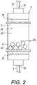
- FIG. 2 is a schematic view of the reaction vessel 9.
- the reaction vessel 9 shown in FIG. 2 is constituted by a vessel that is longer in the vertical direction than in the horizontal direction.
- a large number of carriers B are provided inside the reaction vessel 9.
- the carriers B are shown larger than the actual carriers B to facilitate explanation, and the number thereof shown is also smaller than in reality.
- the reaction vessel 9 may have a form other than what is shown in FIG. 2 , and may be a vessel that is longer in the horizontal direction than in the vertical direction.
- the intermediate pipe 8 is connected to the lower part of the reaction vessel 9.
- a pipe 23 branching off from the gas pipe 17 (see FIG. 1 ) is connected to the upper part of the reaction vessel 9.
- an upper filter 38 is provided at the upper part, and a lower filter 39 is provided at the lower part.
- the upper filter 38 is a net-like member that is permeable to the solution L but impermeable to the carriers B, and is a member that covers the internal space of the reaction vessel 9 from above.
- the lower filter 39 is a net-like member that is permeable to the solution L but impermeable to the carriers B, and is a member that covers the internal space of the reaction vessel 9 from below.
- the lower surface of the upper filter 38 is defined as the vessel upper surface 31, and the upper surface of the lower filter 39 is defined as the vessel lower surface 32.
- the space between the vessel upper surface 31 and the vessel lower surface 32 is a reaction space 30, and a large number of the carriers B are provided in this reaction space 30.
- the carriers B do not completely fill the reaction space 30, and instead are provided up to a first height position P1 located part of the way up in the vertical direction of the reaction space 30. Therefore, this produces a space Q1 in the reaction vessel 9 above the layer of the carriers B.
- FIG. 3 is an explanatory diagram showing a state in which the solution L has been supplied to the reaction vessel 9 containing the carriers B.
- the solution L is supplied through the intermediate pipe 8, from the lower side of the reaction vessel 9.
- Various kinds of solution L are supplied to the reaction vessel 9, as mentioned above. Regardless of which solution L is supplied, the solution L does not fill the reaction vessel 9. That is, the solution L is not supplied until the reaction space 30 is full, but rather is supplied up to a second height position P2 located part of the way up in the vertical direction of the reaction space 30.
- This height position P2 is based on the supplied solution L and the carriers B that have been provided in advance. Therefore, inside the reaction vessel 9, this produces a space Q2 above the layer (mixed layer) of the carriers B and the solution L.
- the volume of the space Q2 may be larger than the combined volume of the carriers B and the solution L.
- the cross-sectional area of the reaction space 30 is constant in the vertical direction, so the height H1 of the space Q2 is greater than the height H2 of the layer between the carriers B and the solution L.
- the method for sending the solution L to the reaction vessel 9 is pressure feeding by means of the gas in the tank 4 (see FIG. 1 ), and this pressure feeding is performed by the gas supply means 20.
- the solution L sent to the reaction vessel 9 is a solution that has been measured by the measuring mechanism 15. That is, the amount of the solution L supplied to the reaction vessel 9 is controlled, and as discussed above (see FIG. 3 ), this results in a state in which the solution L has been supplied up to the second height position P2 part of the way up in the reaction space 30 in the vertical direction.
- the volume of the reaction vessel 9 (reaction space 30) is set large. More specifically, the volume of the reaction vessel 9 (reaction space 30) is set large enough that even if the preset maximum amount of the solution L is supplied to the reaction vessel 9, the height of the liquid surface of the solution L will be at the second height position P2 part of the way up in the vertical direction of the reaction space 30. That is, in a state where the required amount of solution L has been supplied to the reaction vessel 9 containing the carriers B, the volume of the reaction vessel 9 will be greater than the combined volume of the required amount of solution L and the carriers B.
- the vessel upper surface 31 of the reaction vessel 9 is located higher than the upper surface S of the layer of the carriers B and the solution L.
- the vessel upper surface 31 is the lower surface of the upper filter 38.
- the volume of the reaction vessel 9 is greater than the volume of the supplied solution L.
- the volume of the reaction vessel 9 is preferably at least 2.5 times the volume (maximum required amount) of the solution L, and is also preferably no more than 4 times the volume of the solution L so as not to make the reaction vessel 9 any larger than necessary.
- FIG. 4 is an explanatory diagram showing a state in which gas is being supplied to the reaction vessel 9.
- the solution L is supplied to the reaction vessel 9 containing the carriers B
- the solution L and the carriers B are agitated by this supply of gas to the reaction vessel 9.
- the synthesis device 1 disclosed herein see FIG. 1
- the solution L measured by the measuring mechanism 15 is pushed through the intermediate pipe 8 connected to the reaction vessel 9 by the gas of the tank 4, and conveyed to the reaction vessel 9 .
- This conveyance is performed by the gas supply means 20, as mentioned above.
- the gas used to convey the solution L is supplied directly to the reaction vessel 9. Therefore, as shown in FIG. 4 , the carriers B and the solution L can be agitated by the gas inside the reaction vessel 9. That is, the gas for stirring the carriers B and the solution L is supplied by the gas supply means 20.
- the supply of gas for stirring is continued for a specific length of time. As shown in FIGS. 3 to 4 , once the required amount of solution L has been supplied to the reaction vessel 9, the state of stirring with the gas is continued. In the case of the synthesis device 1 disclosed herein, the solution L is not supplied to the reaction vessel 9 while the gas is being supplied to the reaction vessel 9 for stirring. Some of the gas supplied to the reaction vessel 9 is discharged to the outside of the reaction vessel 9 (outside of the synthesis device 1) through the pipe 23.
- the space Q2 is produced above the layer (mixed layer) of the carriers B and the solution L. Therefore, even when gas is added to the reaction vessel 9 for stirring, the carriers B and the solution L including the gas will not reach (are unlikely to reach) the vessel upper surface 31. That is, as shown in FIG. 4 , even when gas is supplied into the reaction vessel 9, a space Q3 is produced at the upper part of the container in the reaction space 30, and the solution L and the carriers B can flow so as to escape to the space Q3 at the upper part of the vessel. Therefore, the gas briskly stirs the carriers B and the solution L.
- the supply of gas produces a mixed flow of the solution L and the carriers B, containing the gas, inside the reaction vessel 9.
- the vessel upper surface 31 is located higher than the height of the upper surface of this mixed flow.
- a plurality of carriers B may be present as a clump in the reaction vessel 9.
- the carriers B at the center of this clump will be less likely to come into contact with the solution L.
- clumping is eliminated by the stirring, that is, the carriers B are dispersed in the solution L, and more of the carriers B come into contact with the solution L.
- the carriers B and the solution L including the gas will not reach (are unlikely to reach) the vessel upper surface 31.
- the carriers B may move so vigorously that some of the carriers B may stick to the vessel upper surface 31. In this event, those carriers B may not be able to come into contact with the solution L and may not contribute to the production of the target substance (nucleic acid).
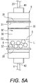
- the reaction vessel 9 may have an internal filter 35.
- FIGS. 5A and 5B are explanatory views showing a modification example of the reaction vessel 9. Similar to the upper filter 38 and the lower filter 39, the internal filter 35 is constituted by a mesh-like member that is permeable to the solution L but is impermeable to the carriers B. As shown in FIG. 5A , this internal filter 35 is provided at a position higher than the upper surface of the layer of the carriers B in a state before the gas has been supplied to the reaction vessel 9. Furthermore, as shown in FIG. 5B , the internal filter 35 is provided at a position lower than the height of the liquid surface of the solution L containing the gas in a state in which the gas has been supplied to the reaction vessel 9.
- the internal filter 35 Since the internal filter 35 is provided at the position described above, the carriers B will not stick to the vessel upper surface 31. Furthermore, even if the carriers B should move and stick to the internal filter 35, they can be mixed with the solution L, and those carriers B will also contribute to the production of the target substance (nucleic acid). Thus, when the reaction vessel 9 has the internal filter 35, it is possible to prevent some of the carriers B from sticking to the vessel upper surface 31 of the reaction vessel 9 and being unable to come into contact with the solution L. When the internal filter 35 is provided, the upper filter 38 may be omitted.
- reaction vessel 9 is as shown in FIGS. 2 , 3 and 4 (first mode), or the reaction vessel 9 is as shown in FIGS. 5A and 5B (second mode), once the chemical reaction with the solution L has taken place for a specific length of time, the solution L is discharged to the outside of the reaction vessel 9.
- the means for this discharge is as follows.
- the stirring is halted in the reaction vessel 9.
- the supply of gas to the reaction vessel 9 is stopped.
- the gas valve 19 provided along the gas pipe 17 (see FIG. 1 ) is switched so that the gas in the tank 4 flows through the pipe 23 connected to the reaction vessel 9.
- the valve 25 provided along the intermediate pipe 8 is also switched so that the reaction vessel 9 is connected to the discharge pipe 26. Consequently, the gas in the tank 4 is supplied to the reaction vessel 9, and the used solution L in the reaction vessel 9 is pushed by the gas and discharged from the discharge pipe 26 into the waste liquid tank 27.
- the gas in the tank 4 is supplied to the reaction vessel 9 from the upper part of the vessel. Therefore, even if some of the carriers B stick to the vessel upper surface 31 (upper filter 38) or some of the carriers B stick to the internal filter 35 (see FIG. 5A ), those carriers B can be knocked down to the bottom of the reaction vessel 9.
- the reaction vessel 9 has an upper port 41 and a lower port 42.
- the pipe 23 branching off from the gas pipe 17 is connected to the upper port 41, and the intermediate pipe 8 is connected to the lower port 42.
- the upper port 41 serves as a gas inlet
- the lower port 42 serves as a solution L discharge port. That is, the reaction vessel 9 has at its upper part an inflow port (upper port 41) through which passes the gas for discharging the solution L to the outside of the reaction vessel 9.
- the reaction vessel 9 has at its lower part a discharge port (lower port 42) through which the solution L is discharged as a waste liquid.
- the synthesis device 1 in each of the modes described above comprises a reaction vessel 9 and a gas supply means 20 capable of supplying gas to this reaction vessel 9.
- the reaction vessel 9 contains a large number of carriers B and is supplied with the solution L used for chemical synthesis.
- the gas supply means 20 stirs the solution L and the carriers B by supplying gas to the reaction vessel 9 during chemical synthesis in the reaction vessel 9.
- the carriers B are dispersed in the solution L in the reaction vessel 9, allowing the solution L to come into contact with all of the many carriers B. As a result, fewer of the carriers B are unlikely to react than in the past.
- carriers B that have stuck to the side wall surface of the reaction vessel 9 can move to the center of the reaction vessel 9, or carriers B that have clumped together can be dispersed, allowing more of the carriers B to come into contact with the solution L. As a result, it is possible to improve the yield of the target substance (nucleic acid) obtained by chemical synthesis.
- the synthesis method performed by the synthesis device 1 in each of the above-mentioned mode includes the following steps.
- FIG. 6 is a flowchart illustrating this synthesis method.
- the solution L is supplied to the reaction vessel 9 by pressure feeding a gas.
- the gas supply parameters such as the pressure and the flow rate of the gas, are controlled by the control device 16. This control is preferably performed by adjusting the supply parameters according to the type of solution L.
- the gas supply parameters when the solution L is supplied to the reaction vessel 9 in the supply step S2, and the gas supply parameters when the gas is supplied to the reaction vessel 9 for stirring in the synthesis step S3, may be the same or may be different.
- the synthesis method disclosed herein also includes the following steps.
- the required amount of solution L is measured.
- the discharge step S4 as described above, if gas is supplied from the upper part (upper port 41) of the reaction vessel 9, the used solution L is discharged as waste liquid from the lower part (lower port 42) of the reaction vessel 9.
- the processing proceeds to the measurement step S1, and the next measurement of the solution L is performed. After this, the supply step S2, the synthesis step S3, and the discharge step S4 are repeated until all the synthesis is complete.
- the synthesis method disclosed herein is not a method in which the solution L is circulated by using the reaction vessel 9 as one of the flow paths, and is instead a method in which a mixed flow of the solution L and the carriers B is produced inside the reaction vessel 9 by the gas supplied to the reaction vessel 9. It is therefore possible to reduce the amount of solution L used, and the chemical synthesis also takes less time.
- gas is supplied for stirring to the reaction vessel 9 containing the carriers B and the solution L. Therefore, a flow of the solution L, the carriers B, and the gas is produced in the reaction vessel 9, and the volume of the contents of the reaction vessel 9 is greater than that before the supply of gas.
- the vessel upper surface 31 of the reaction vessel 9 is set to be located higher than the upper surface of the layer of the carriers B and the solution L.
- the carriers B and the required amount of solution L are held in the lower part of the reaction vessel 9, and the space Q2 is formed in the upper part of the reaction vessel 9. Therefore, in the subsequent synthesis step S3, when gas is supplied to the reaction vessel 9 (see FIG. 4 ), the solution L and the carriers B can flow so as to escape to the space at the upper part of the vessel, and the solution L and the carriers B can be stirred more vigorously.
- the solution L would end up flowing out of the pipe 23 connected to the upper part of the reaction vessel 9.
- the solution L can be prevented from flowing out of the pipe 23 by setting the volume of the reaction vessel 9 such that the upper surface 31 of the reaction vessel 9 is higher than the upper surface of the layer of the carriers B and the solution L.
- the solution L measured by the measuring mechanism 15, that is, a solution L that is outside of the reaction vessel 9, is pushed by gas through the intermediate pipe 8 connected to the reaction vessel 9, and conveyed to the reaction vessel 9. Then, when the conveyance of the solution L to the reaction vessel 9 by the gas is complete, in the synthesis step S3, the gas that was used to convey the solution L is supplied directly to the reaction vessel 9, and the carriers B and the solution L are stirred by this gas.
- the conveyance of the solution L by gas to the reaction vessel 9 and its stirring by the gas are performed by the gas supply means 20.
- the gas that conveys the solution L to the reaction vessel 9 is used to stir the carriers B and the solution L. If a mechanism for conveying the solution L to the reaction vessel 9 by gas is provided, there will be no need to separately provide a gas supply mechanism for stirring, and the configuration of the synthesis device 1 can be simplified.
- the gas used to pressure-feed the solution L from the storage container 2 to the measuring mechanism 15, the gas used to pressure-feed the solution L from the measuring mechanism 15 to the reaction vessel 9, and the gas used to stir the carriers B and the solution L in the reaction vessel 9 are all supplied from the same tank 4.
- the configuration may instead be such that these gases are supplied from different tanks (gas sources).
- a gas used for pressure-feeding and a gas used for stirring may be supplied from different tanks (gas sources).
- the flow path for supplying the solution L to the reaction vessel 9 and the flow path for supplying the gas for stirring are the same (both use the intermediate pipe 8), but the flow path for supplying the solution L to the reaction vessel 9 and the flow path for supplying the gas for stirring to the reaction vessel 9 may be different. Also, the reaction vessel 9 may have a shape other than what is shown in the drawings.
- a gas is supplied from the lower part of the reaction vessel 9 for stirring.
- an internal pipe may be provided so as to extend from the upper part of the reaction vessel 9 into the layer of the carriers B and the solution L, and gas may be supplied through this internal pipe into the layer for stirring.
- chemical synthesis can be performed while stirring the solution L and the carriers B.
Landscapes
- Chemical & Material Sciences (AREA)
- Organic Chemistry (AREA)
- Health & Medical Sciences (AREA)
- Life Sciences & Earth Sciences (AREA)
- Engineering & Computer Science (AREA)
- Genetics & Genomics (AREA)
- Bioinformatics & Cheminformatics (AREA)
- Zoology (AREA)
- Wood Science & Technology (AREA)
- Chemical Kinetics & Catalysis (AREA)
- General Health & Medical Sciences (AREA)
- Biochemistry (AREA)
- Biomedical Technology (AREA)
- Biotechnology (AREA)
- General Engineering & Computer Science (AREA)
- Molecular Biology (AREA)
- Microbiology (AREA)
- Sustainable Development (AREA)
- Biophysics (AREA)
- Medicinal Chemistry (AREA)
- Analytical Chemistry (AREA)
- Proteomics, Peptides & Aminoacids (AREA)
- Combustion & Propulsion (AREA)
- Crystallography & Structural Chemistry (AREA)
- Plant Pathology (AREA)
- Physics & Mathematics (AREA)
- Clinical Laboratory Science (AREA)
- Physical Or Chemical Processes And Apparatus (AREA)
- Apparatus Associated With Microorganisms And Enzymes (AREA)
- Mixers With Rotating Receptacles And Mixers With Vibration Mechanisms (AREA)
- Feeding, Discharge, Calcimining, Fusing, And Gas-Generation Devices (AREA)
- Devices And Processes Conducted In The Presence Of Fluids And Solid Particles (AREA)
- Peptides Or Proteins (AREA)
Applications Claiming Priority (2)
| Application Number | Priority Date | Filing Date | Title |
|---|---|---|---|
| JP2019228421A JP2021094533A (ja) | 2019-12-18 | 2019-12-18 | 合成装置及び合成方法 |
| PCT/JP2020/034738 WO2021124627A1 (ja) | 2019-12-18 | 2020-09-14 | 合成装置及び合成方法 |
Publications (2)
| Publication Number | Publication Date |
|---|---|
| EP4079397A1 true EP4079397A1 (de) | 2022-10-26 |
| EP4079397A4 EP4079397A4 (de) | 2023-07-05 |
Family
ID=76430322
Family Applications (1)
| Application Number | Title | Priority Date | Filing Date |
|---|---|---|---|
| EP20903555.9A Withdrawn EP4079397A4 (de) | 2019-12-18 | 2020-09-14 | Synthesevorrichtung und syntheseverfahren |
Country Status (5)
| Country | Link |
|---|---|
| US (1) | US20230024632A1 (de) |
| EP (1) | EP4079397A4 (de) |
| JP (1) | JP2021094533A (de) |
| CN (1) | CN114650998A (de) |
| WO (1) | WO2021124627A1 (de) |
Families Citing this family (2)
| Publication number | Priority date | Publication date | Assignee | Title |
|---|---|---|---|---|
| WO2022202191A1 (ja) * | 2021-03-24 | 2022-09-29 | 東レエンジニアリング株式会社 | 薬液合成装置 |
| JP2023146117A (ja) * | 2022-03-29 | 2023-10-12 | 東レエンジニアリング株式会社 | 薬液合成方法及び薬液合成装置 |
Family Cites Families (25)
| Publication number | Priority date | Publication date | Assignee | Title |
|---|---|---|---|---|
| JPS54117379A (en) * | 1978-03-06 | 1979-09-12 | Tokyo Rikakikai Kk | Contacting reactor |
| JPS60105692A (ja) * | 1983-11-14 | 1985-06-11 | Nippon Zeon Co Ltd | ポリヌクレオチド合成装置 |
| JPS60137288A (ja) * | 1983-12-27 | 1985-07-20 | Chiyoda Chem Eng & Constr Co Ltd | 生物反応方法 |
| US4668476A (en) * | 1984-03-23 | 1987-05-26 | Applied Biosystems, Inc. | Automated polypeptide synthesis apparatus |
| US4983517A (en) * | 1986-08-22 | 1991-01-08 | Battelle Memorial Institute | Reacting materials |
| JPS6379898A (ja) * | 1986-09-22 | 1988-04-09 | Nippon Zeon Co Ltd | ポリヌクレオチド合成反応における脱保護基反応の制御方法 |
| US5252296A (en) * | 1990-05-15 | 1993-10-12 | Chiron Corporation | Method and apparatus for biopolymer synthesis |
| US5563068A (en) * | 1994-04-21 | 1996-10-08 | Genetic Therapy, Inc. | Bioreactor |
| US5880311A (en) * | 1994-07-22 | 1999-03-09 | Tonen Corporation | Method of contacting catalyst particles with gas and liquid |
| JP4415414B2 (ja) * | 1998-09-25 | 2010-02-17 | 株式会社島津製作所 | 自動合成装置 |
| JP2001129575A (ja) * | 1999-11-04 | 2001-05-15 | Mitamura Setsubi Sekkei Jimusho:Kk | 汚水処理用微生物培養装置 |
| JP2001340075A (ja) * | 2000-05-31 | 2001-12-11 | Nisshinbo Ind Inc | バイオリアクター用担体、その製造方法及び該担体の使用方法 |
| US6649051B1 (en) * | 2002-05-01 | 2003-11-18 | Biotage, Inc. | Processing of chemicals in flow-through device with porous media |
| US20060014176A1 (en) * | 2004-05-26 | 2006-01-19 | Iyer Radhakrishnan P | Reactor for chemical synthesis |
| JP2006061097A (ja) * | 2004-08-27 | 2006-03-09 | Hitachi Plant Eng & Constr Co Ltd | 固定化微生物の製造方法、及びそれによって製造された固定化微生物、並びにその固定化微生物を用いた反応装置 |
| CA2825572C (en) * | 2012-09-04 | 2021-01-12 | Jason International, Inc. | Microbubble therapy method and generating apparatus |
| EP2742994A1 (de) * | 2012-12-14 | 2014-06-18 | Emerging Fuels Technology Inc. | Horizontaler Dreiphasenreaktor |
| WO2016117023A1 (ja) * | 2015-01-20 | 2016-07-28 | 三菱化学エンジニアリング株式会社 | 酸素含有気体のマイクロナノバブルを供給する装置及び溶存二酸化炭素を除去する装置を備えた生物反応装置及びこの生物反応装置を用いた生物反応方法 |
| JP2018176021A (ja) * | 2017-04-05 | 2018-11-15 | 日立Geニュークリア・エナジー株式会社 | 容器内析出物処理システム |
| CN206631567U (zh) * | 2017-04-14 | 2017-11-14 | 青岛科技大学 | 一种反应时间可控的气固两相反应器 |
| JP6405483B1 (ja) * | 2018-04-02 | 2018-10-17 | マイクロ波化学株式会社 | 処理装置 |
| CN206980628U (zh) * | 2017-06-30 | 2018-02-09 | 江苏省冶金设计院有限公司 | 一种制备液体粘结剂的系统 |
| JP2019034290A (ja) * | 2017-08-21 | 2019-03-07 | 東レエンジニアリング株式会社 | 合成装置 |
| JP7100473B2 (ja) * | 2018-03-27 | 2022-07-13 | 東レエンジニアリング株式会社 | 合成装置 |
| CN210506367U (zh) * | 2019-05-08 | 2020-05-12 | 南京安佰思生物科技有限公司 | 一种固定化酶的新型反应装置 |
-
2019
- 2019-12-18 JP JP2019228421A patent/JP2021094533A/ja active Pending
-
2020
- 2020-09-14 CN CN202080077878.9A patent/CN114650998A/zh active Pending
- 2020-09-14 WO PCT/JP2020/034738 patent/WO2021124627A1/ja not_active Ceased
- 2020-09-14 US US17/786,316 patent/US20230024632A1/en not_active Abandoned
- 2020-09-14 EP EP20903555.9A patent/EP4079397A4/de not_active Withdrawn
Also Published As
| Publication number | Publication date |
|---|---|
| EP4079397A4 (de) | 2023-07-05 |
| WO2021124627A1 (ja) | 2021-06-24 |
| US20230024632A1 (en) | 2023-01-26 |
| CN114650998A (zh) | 2022-06-21 |
| JP2021094533A (ja) | 2021-06-24 |
Similar Documents
| Publication | Publication Date | Title |
|---|---|---|
| EP4079397A1 (de) | Synthesevorrichtung und syntheseverfahren | |
| US8590581B2 (en) | Method and filling system for filling bottles or similar containers with a liquid filling material and filling material dispensed into containers | |
| JP2019034290A (ja) | 合成装置 | |
| WO2013012984A2 (en) | System and process for delivering building materials | |
| US20130108513A1 (en) | Microfluidic chip and a related method thereof | |
| US7713490B2 (en) | Particulate flow control process | |
| JP2018030610A (ja) | 分注装置および包装物の製造方法 | |
| JP7175740B2 (ja) | 薬液合成装置及び薬液合成方法 | |
| CN102120154A (zh) | 多相混合液体的搅拌方法及其所采用的输送管道连接结构 | |
| CN111905655B (zh) | 一种双酚a钠盐连续进料系统及方法 | |
| JP7100473B2 (ja) | 合成装置 | |
| CN104857887B (zh) | 一种高黏度涂布液的自动加料、配料、供料系统 | |
| CN110832063A (zh) | 用于处理液体样本的方法 | |
| US11439961B2 (en) | Continuous multi-chamber process | |
| US20120298252A1 (en) | Method and plant for filling a bottle with a radioactive fluid-based mixture | |
| JP2025122436A (ja) | 反応容器、及び合成装置 | |
| KR100927097B1 (ko) | 연속 촉매 제조장치 | |
| CN102245497A (zh) | 酒精接收站 | |
| WO2020188976A1 (ja) | 計量機構 | |
| JP2023146136A (ja) | 薬液合成装置 | |
| US20100230271A1 (en) | Devices and methods for performing microwave assisted chemical synthesis | |
| CN220940619U (zh) | 一种用于生产吩噻嗪的微型反应器及反应系统 | |
| JP2023146117A (ja) | 薬液合成方法及び薬液合成装置 | |
| CN111054234A (zh) | 颗粒酱料搅拌罐、颗粒酱料灌装设备及其灌装方法 | |
| CN204195992U (zh) | 一种全自动多种物料精确配比混合搅拌系统 |
Legal Events
| Date | Code | Title | Description |
|---|---|---|---|
| STAA | Information on the status of an ep patent application or granted ep patent |
Free format text: STATUS: THE INTERNATIONAL PUBLICATION HAS BEEN MADE |
|
| PUAI | Public reference made under article 153(3) epc to a published international application that has entered the european phase |
Free format text: ORIGINAL CODE: 0009012 |
|
| STAA | Information on the status of an ep patent application or granted ep patent |
Free format text: STATUS: REQUEST FOR EXAMINATION WAS MADE |
|
| 17P | Request for examination filed |
Effective date: 20220627 |
|
| AK | Designated contracting states |
Kind code of ref document: A1 Designated state(s): AL AT BE BG CH CY CZ DE DK EE ES FI FR GB GR HR HU IE IS IT LI LT LU LV MC MK MT NL NO PL PT RO RS SE SI SK SM TR |
|
| DAV | Request for validation of the european patent (deleted) | ||
| DAX | Request for extension of the european patent (deleted) | ||
| A4 | Supplementary search report drawn up and despatched |
Effective date: 20230602 |
|
| RIC1 | Information provided on ipc code assigned before grant |
Ipc: B01J 19/00 20060101ALI20230526BHEP Ipc: C07K 1/04 20060101ALI20230526BHEP Ipc: C12M 1/40 20060101ALI20230526BHEP Ipc: B01J 4/02 20060101ALI20230526BHEP Ipc: B01J 8/22 20060101AFI20230526BHEP |
|
| STAA | Information on the status of an ep patent application or granted ep patent |
Free format text: STATUS: THE APPLICATION IS DEEMED TO BE WITHDRAWN |
|
| 18D | Application deemed to be withdrawn |
Effective date: 20240103 |