EP4078562B1 - Haftetikett für ein mehrteiliges gefäss, system und verfahren zum applizieren eines haftetiketts an einem mehrteiligen gefäss - Google Patents
Haftetikett für ein mehrteiliges gefäss, system und verfahren zum applizieren eines haftetiketts an einem mehrteiligen gefäss Download PDFInfo
- Publication number
- EP4078562B1 EP4078562B1 EP20807690.1A EP20807690A EP4078562B1 EP 4078562 B1 EP4078562 B1 EP 4078562B1 EP 20807690 A EP20807690 A EP 20807690A EP 4078562 B1 EP4078562 B1 EP 4078562B1
- Authority
- EP
- European Patent Office
- Prior art keywords
- label
- adhesive label
- adhesive
- syringe
- threaded element
- Prior art date
- Legal status (The legal status is an assumption and is not a legal conclusion. Google has not performed a legal analysis and makes no representation as to the accuracy of the status listed.)
- Active
Links
Images


Classifications
-
- G—PHYSICS
- G09—EDUCATION; CRYPTOGRAPHY; DISPLAY; ADVERTISING; SEALS
- G09F—DISPLAYING; ADVERTISING; SIGNS; LABELS OR NAME-PLATES; SEALS
- G09F3/00—Labels, tag tickets, or similar identification or indication means; Seals; Postage or like stamps
- G09F3/02—Forms or constructions
- G09F3/0288—Labels or tickets consisting of more than one part, e.g. with address of sender or other reference on separate section to main label; Multi-copy labels
-
- G—PHYSICS
- G09—EDUCATION; CRYPTOGRAPHY; DISPLAY; ADVERTISING; SEALS
- G09F—DISPLAYING; ADVERTISING; SIGNS; LABELS OR NAME-PLATES; SEALS
- G09F3/00—Labels, tag tickets, or similar identification or indication means; Seals; Postage or like stamps
- G09F3/02—Forms or constructions
- G09F3/0291—Labels or tickets undergoing a change under particular conditions, e.g. heat, radiation, passage of time
- G09F3/0292—Labels or tickets undergoing a change under particular conditions, e.g. heat, radiation, passage of time tamper indicating labels
-
- G—PHYSICS
- G09—EDUCATION; CRYPTOGRAPHY; DISPLAY; ADVERTISING; SEALS
- G09F—DISPLAYING; ADVERTISING; SIGNS; LABELS OR NAME-PLATES; SEALS
- G09F3/00—Labels, tag tickets, or similar identification or indication means; Seals; Postage or like stamps
- G09F3/02—Forms or constructions
- G09F3/03—Forms or constructions of security seals
- G09F3/0305—Forms or constructions of security seals characterised by the type of seal used
- G09F3/0341—Forms or constructions of security seals characterised by the type of seal used having label sealing means
-
- G—PHYSICS
- G09—EDUCATION; CRYPTOGRAPHY; DISPLAY; ADVERTISING; SEALS
- G09F—DISPLAYING; ADVERTISING; SIGNS; LABELS OR NAME-PLATES; SEALS
- G09F3/00—Labels, tag tickets, or similar identification or indication means; Seals; Postage or like stamps
- G09F3/08—Fastening or securing by means not forming part of the material of the label itself
- G09F3/10—Fastening or securing by means not forming part of the material of the label itself by an adhesive layer
-
- G—PHYSICS
- G09—EDUCATION; CRYPTOGRAPHY; DISPLAY; ADVERTISING; SEALS
- G09F—DISPLAYING; ADVERTISING; SIGNS; LABELS OR NAME-PLATES; SEALS
- G09F3/00—Labels, tag tickets, or similar identification or indication means; Seals; Postage or like stamps
- G09F3/02—Forms or constructions
- G09F2003/0264—Shapes or borders
- G09F2003/0269—Shapes or borders perforated
-
- G—PHYSICS
- G09—EDUCATION; CRYPTOGRAPHY; DISPLAY; ADVERTISING; SEALS
- G09F—DISPLAYING; ADVERTISING; SIGNS; LABELS OR NAME-PLATES; SEALS
- G09F3/00—Labels, tag tickets, or similar identification or indication means; Seals; Postage or like stamps
- G09F3/02—Forms or constructions
- G09F2003/0272—Labels for containers
-
- G—PHYSICS
- G09—EDUCATION; CRYPTOGRAPHY; DISPLAY; ADVERTISING; SEALS
- G09F—DISPLAYING; ADVERTISING; SIGNS; LABELS OR NAME-PLATES; SEALS
- G09F3/00—Labels, tag tickets, or similar identification or indication means; Seals; Postage or like stamps
- G09F3/02—Forms or constructions
- G09F2003/0272—Labels for containers
- G09F2003/0273—Labels for bottles, flasks
Definitions
- the present invention relates to an adhesive label for a multi-part vessel that can contribute to reliable coupling of vessel components and secure tamper protection for the vessel in a simple and cost-effective manner.
- the invention also relates to a system comprising such an adhesive label and a multi-part vessel, as well as a method for applying such an adhesive label to a multi-part vessel.
- a label can be used, in particular, to identify or prove the origin of an object to be labeled.
- labels are used when it is necessary to indicate the contents of a container. This particularly applies to containers in the pharmaceutical and medical sectors, whose contents must be protected against tampering.
- the document EP2014570A is considered to be the closest state of the art.
- an adhesive label for a multi-part vessel having a threaded element and a vessel body comprises a first, flat label portion configured to be attached to the threaded element of the vessel.
- the adhesive label further comprises a second label portion adjacent to the first label portion and having a comb-like structure with a plurality of spaced-apart strip-shaped fixing elements.
- the second label portion with the Fixing elements are designed to be attached to the vessel body of the vessel, so that the adhesive label couples the threaded element to the vessel body and counteracts movement of the threaded element relative to the vessel body.
- the described adhesive label enables a reliable and cost-effective fixation of a threaded element to the associated body, while also contributing to secure tamper protection.
- the adhesive label is particularly suitable for packaging or containers in the pharmaceutical sector, such as syringes, injection vials, or vials, which typically include a threaded element that is attached or plugged onto the associated container body.
- the threaded element comprises, for example, a section with an internal thread, which forms a type of threaded head adjacent to a section that allows it to be placed or plugged onto the vessel body.
- the threaded element is provided with a thread over its entire outer surface.
- the threaded section is coupled to a closure, which forms a cap for the vessel and securely closes it.
- the threaded element which is usually formed from a plastic part and provided with a threaded section, is pushed onto the front of the glass syringe.
- a plastic threaded element is attached to the glass syringe by mechanical interlocking or adhesive bonding.
- an attachment of the threaded element to syringes is often not sufficient. It can happen that when screwing in a syringe needle, the mechanical or adhesive coupling does not hold and the threaded element rotates with it, especially if the user does not hold the threaded element firmly when screwing in the syringe needle. It can also happen that when using highly viscous formulations, the syringe needle flakes off together with the threaded element.
- the described adhesive label enables the threaded element to be fixed, particularly in the form of a Luer-Lock thread on syringes, so that in the case of application The Luer Lock thread is sufficiently firmly attached to the syringe. Additionally, the adhesive label, particularly in conjunction with the threaded element, can be designed to provide a first-opening indicator.
- the adhesive label can be used to surround the container like a second skin, providing additional protection, such as UV radiation, for the medication contained in the container.
- the strip-shaped fixing elements each have a predetermined orientation transverse to the first label section and each form a predetermined angle with an adjacent edge of the first label section.
- one or more of the fixing elements can each form an angle of less than 90° or greater than 90° with the adjacent edge of the first label section.
- the fixing elements according to such a configuration enclose the circumference of the vessel body in a spiral shape and reliably counteract unwanted co-rotation of the threaded element when the vessel is opened.
- some strip-shaped fixing elements form an angle of less than 90° with the adjacent edge of the first label section, and further strip-shaped fixing elements form an angle of greater than 90°.
- the adhesive label has a comb-like structure with sections that are directed towards one another. When applied to the vessel, the respective fixing elements enclose the circumference of the vessel body in a spiral manner and come to rest on one another in sections.
- the differently aligned sections of the comb-like structure are preferably each formed externally at opposite ends of the adhesive label.
- the adhesive label and the fixing elements are designed to be wide or long enough to create a wraparound label for the container to which the adhesive label is to be applied.
- the first label section is wrapped around the threaded element, and the second label section is wrapped around the container body, so that the external fixing elements cross over and cover each other in sections. This allows for a particularly stable hold of the adhesive label on the container, and reliably counteracts any relative movement of the threaded element relative to the container body.
- the first label section is further designed to extend into the region of a closure of the vessel and in particular to be attached thereto, such that the adhesive label further couples the closure to the vessel body.
- the adhesive label can surround the closure more or less contactlessly and form a type of sleeve around it or alternatively be connected to it, for example, by adhesive bonding.
- the first label section of the adhesive label is in particular adhesively bonded to the threaded element and can also enclose the closure of the vessel in a sleeve-like manner without being adhesively coupled to it or to it. The first label section can thus enclose the closure all around its longitudinal axis without contact or adhesive bonding.
- first label section then forms a label sleeve that is open upwards with respect to the longitudinal axis.
- first label section is then pressed against an outer surface of the closure and separated from a lower part of the first label section and from the second label section by pulling and/or turning and removed from the vessel body together with the closure of the vessel.
- top and bottom refer to the proper arrangement or application of the label and the container. This also applies to terms such as “head” and “body,” where the head is generally positioned at the top and the body is usually positioned at the bottom.
- the closure of the container forms the upper part of a head of an injection vial or syringe and includes, for example, a cap, a lid, or a primary closure or a primary cap, which is removed to open the container.
- the vessel body then forms, for example, the lower part of a container of the injection vial or syringe for receiving and storing a given content.
- the first label section of the adhesive label is assigned to the upper component of the vessel and thus to the threaded element and/or the closure and can therefore also be referred to as the upper label section.
- the second label section of the adhesive label is assigned to the lower component of the vessel and remains on the vessel body or the container of the vessel after opening and can therefore also be referred to as the lower label section.
- a reversed orientation and use of the adhesive label is also possible, in which the fixing elements are attached to the threaded element and this is fixed with respect to relative movements by means of the first label section, which is then placed on the vessel body.
- the described embodiments of the adhesive label in which the upper label section extends to the closure of the container, are particularly suitable for providing proof of opening and tamper protection in addition to the fixed hold of the threaded element.
- the closure Upon opening the container, the closure is removed from the threaded element and, for example, pulled or torn off from the remaining portion together with a partial element of the first label section. Accordingly, the opening of the container can be recognized by the part of the adhesive label remaining on the container body.
- the first label section is preferably configured such that only a narrow gap or space exists between the closure and the surrounding first label section. Manipulation or an attempt to open the label by reaching into the narrow space from above would result in tearing or crumpling of the first label section, so that such an action would leave recognizable traces.
- the adhesive label can in particular be designed as an adhesive label, so that it partially or completely covers the threaded element and the vessel body with respect to a circumference. completely covered.
- the adhesive label can be designed in particular such that the first and/or the second label section is designed to match a circumference of the threaded element and/or the closure and/or the vessel body of the vessel to be provided with the adhesive label and has a predetermined length.
- the adhesive label can thus be designed partially or completely as an all-round or over-all label.
- the first label section is designed as an over-all section in terms of its length so that when applied it completely encloses a circumference of the threaded element and partially covers or overlaps itself, while the second label section only covers part of the outer surface of the vessel body and does not enclose it all the way around.
- the second label section is designed as an over-all section in terms of its length so that when applied it completely surrounds a circumference of the vessel body.
- the first label section is designed to match a surface structure of the threaded element and/or the closure of the vessel to which the adhesive label is to be applied and has a predetermined punched-out portion or recess.
- a recess can in particular be designed as a punched-out recess complementary to a protrusion or one or more projecting regions.
- knobs or an annular protrusion are provided on the threaded element and/or the closure of the vessel, so that the adhesive label, adapted to the respective surface structure, has circular or elongated or annular recesses that correspond to the surface structure.
- the adhesive label has an elongated recess coordinated with such a protrusion, which, when applied to the vessel, forms a substantially annular recess.
- the adhesive label has at least one holding web, preferably two spaced holding webs or several equidistantly arranged holding webs, so that the lower, second label section is connected to the upper, first label section.
- the first label section is adapted to a surface structure of the threaded element and/or the closure and has at least partial multi-layering.
- the second label section with the comb-like structure can also be designed to match a surface structure and/or a circumference of the vessel body to which the adhesive label is to be applied and can have at least partial multi-layering.
- the adhesive label with multiple layers can, for example, compensate for different radii or diameters of a cylindrical vessel to which the adhesive label is to be applied. Small diameter differences between the threaded element and the vessel body can be overcome by the comb structure of the second label section, even with just one layer.
- multi-layering can contribute to detection of opening, so that, for example, a section of an upper layer is predefined when the labeled vessel is opened, and an underlying area of a lower layer is specifically exposed to clearly indicate that an opening has occurred.
- the exposed section of such a lower layer is, for example, color-coded or has a predefined text, such as "used,”"open,” or "opened.”
- the adhesive label preferably has an adhesive layer arranged on an underside of the first and/or second label section, such that the adhesive label can be arranged on the container by means of adhesive bonding.
- the adhesive layer can completely or partially cover the underside of the adhesive label.
- the adhesive layer can be designed to match a material or surface structure of the threaded element, the closure, and/or the container.
- An adhesive of the adhesive layer is specifically selected, for example, taking into account a surface roughness of the threaded element, in order to ensure a stable hold of the adhesive label on the container and a reliable fixation of the threaded element.
- the adhesive label in particular the first label section, has a cutting area with a cutting element, so that when the container applied with the adhesive label is opened, the adhesive label can be cut along the cutting area in a predetermined manner, so that at least one The first sub-element of the first label section, together with the closure of the vessel, is removable from a second sub-element of the first label section and the vessel body of the vessel.
- the adhesive label can have an adhesive-free surface in the cutting region, so that when the applied vessel is opened, the adhesive label can be easily and reliably cut along the cutting element.
- the cutting element can, in particular, be designed as a perforation and enable a predetermined tearing action.
- the adhesive label can have a film or film element in the cutting area that has a relatively low tear resistance, allowing the film element and thus the adhesive label to be easily torn and severed.
- a film element is designed, for example, as an acetate film and does not require a separate perforation or other weakening structure to enable easy cutting.
- the adhesive label also has an adhesive surface in an upper region of the first label section, which faces away from the second label section.
- the adhesive area of the first label section is then bonded to a closure of the container and can be removed from the remaining adhesive label and the threaded element or container body when the container is opened with the closure.
- no separate segment remains as waste for disposal.
- the adhesive label extends to a closure of the container and the closure or the adhesive label itself includes a cutting area
- the adhesive label preferably has an adhesive-free surface in the cutting area. This allows for easier cutting of the adhesive label and removal of the detachable part of the first label section. The force required to separate the adhesive label is reduced compared to a fully adhesive adhesive label, and the opening dynamics of the container applied with the adhesive label are improved.
- the respective cutting area can be designed, in particular in coordination with the vessel to be applied, in an area of the adhesive label which, when applied to the vessel, corresponds to a transition between the closure and the Threaded element or is assigned to the threaded element and the vessel body.
- the severing area is located, for example, in an area of a lower end of the closure. Sufficiently strong turning and/or pulling on the closure of the vessel then leads to a severing of the adhesive label.
- the severing area can also be arranged in other areas which enable the adhesive label to be separated when the vessel is opened.
- the severing area can, for example, be arranged significantly below the area of the lower end of the closure, so that an upper or outward-facing layer of the adhesive label tears in a predetermined manner due to an acting tensile and/or twisting force.
- a cutting element for example in the form of a perforation or a tear strip, can be provided in the cutting area, which enables controlled cutting of the adhesive label.
- the adhesive label for example in the area of the first label section, can be designed with predetermined surface properties that allow the user to open the container and cut through the adhesive label more easily.
- Such beneficial surface properties can be realized, for example, with anti-slip coatings, printed tactile elements, or surface microstructuring, which enable a more secure grip of the first label section.
- the adhesive label comprises an opening detection element that is integrated into or coupled to the first label section and that is designed to indicate the removal of at least a first partial element of the first label section from the second label section and the container body of the container.
- the opening detection element can interact, in particular, with the previously described severing element in the form of a perforation and clearly indicate a predetermined tearing of the adhesive label.
- the opening detection element can be implemented in the form of a colored area or a background lettering that is exposed when the container provided with the adhesive label is opened.
- the adhesive label can comprise an electronic opening verification element in the form of an RFID transponder, which is coupled to the first label section and comprises a chip and an antenna structure connected to the chip by means of a conductor track.
- the conductor track extends in particular into the severance region and covers the severance element at least in sections.
- the adhesive label described helps prevent the threaded element from rotating when the container is opened or a syringe needle is inserted. Furthermore, the adhesive label can contribute to tamper protection for the container, which can, for example, guarantee the intactness of a medication package or indicate such integrity. By clearly indicating that the container has been opened for the first time, the adhesive label can indicate any unintentional or unauthorized reuse of the correspondingly labeled container after its use. Thus, the adhesive label also counteracts the possibility of tampering with the container.
- the invention comprises a use of an embodiment of the described adhesive label for a vessel that can be divided into several parts for fixing a threaded element to a vessel body of the vessel.
- a system comprises a multi-part vessel having a threaded element and a vessel body, as well as an adhesive label applied to the vessel such that a first label portion of the adhesive label is attached to the threaded element and a second label portion of the adhesive label is attached to the vessel body, such that the adhesive label couples the threaded element to the vessel body and counteracts movement of the threaded element relative to the vessel body.
- the adhesive label can be designed as a full-surface label, which is used to fix the threaded element to the vessel body and to the vessel body.
- the adhesive label of the system is preferably designed according to one of the previously described embodiments.
- the first, flat label section is attached to the threaded element of the vessel and the strip-shaped fixing elements of the comb-like structure of the second label section are attached to the vessel body of the vessel.
- the system may further comprise a closure coupled to the vessel, such that the threaded element is arranged between the vessel body and the closure, wherein the first label portion then extends, in particular, to the closure or onto the closure.
- the adhesive label and the threaded element and/or the closure and/or the vessel body are configured to coordinate with one another. This takes into account, among other things, the geometries, surface structures, and materials of the interacting components.
- the system comprises an opening detection element coupled to the threaded element and/or the closure and configured to indicate removal of the closure from the container body.
- an opening detection element of the container can be configured alternatively or in addition to the previously described opening detection element of the adhesive label.
- the closure is connected to the threaded element by means of connecting webs that break open when the container is opened, thereby providing visible evidence of an opening.
- a method for applying an adhesive label to a multi-part vessel having a threaded element and a vessel body comprises providing the vessel with the threaded element and the vessel body and providing the adhesive label having a first label portion and a second label portion adjacent to the first label portion. The method further comprises applying the adhesive label to the vessel such that the first label portion is attached to the threaded element of the vessel and the second label portion is attached to the vessel body of the vessel, such that the adhesive label couples the threaded element to the vessel body and resists movement of the threaded element relative to the vessel body.
- the adhesive label is designed, in particular, in one of the previously described configurations, so that the application of the adhesive label comprises attaching the fixing elements of the comb-like structure to the vessel body of the vessel.
- the fixing elements are, in particular, wound spirally around the vessel body and attached thereto in such a way that they form a wraparound label with respect to a circumference of the vessel body, and at least one fixing element partially covers another fixing element.
- the described application method it is possible to specifically attach the adhesive label to the vessel in order to establish a secure and reliable hold for the threaded element and to secure or fix it against undesired rotation relative to the vessel body. Because the method relates in particular to applying or attaching an embodiment of the described adhesive label, the described properties and features of the adhesive label are also disclosed for the method, and vice versa.
- the described adhesive label also enables, in particular, subsequent fixing of a threaded element relative to a threaded body, for example, of prefilled syringes.
- the adhesive label can be easily and cost-effectively applied to the container and does not require, for example, a temperature application, as is the case with shrink film, which is wrapped around elements to secure them and then shrinks through the application of heat. However, this also exposes the contents of the container to temperature, and a corresponding process step in a packaging line is required.
- the adhesive label described does not require any temperature application and can be provided in the form of a film with a pressure-sensitive adhesive. that can be easily and reliably applied to the vessel. The use of shrink wrap can therefore be avoided.
- the adhesive label has a special label structure in which, in particular, the comb-like structure of the second label section serves, on the one hand, to bridge the different circumferences of the Luer Lock thread and the syringe body and, on the other hand, to reliably absorb force when rotational forces occur.
- the adhesive label enables simultaneous detection of the syringe barrel and the outside of the Luer Lock thread and, in various embodiments, also detection of the vessel closure if the adhesive label is also intended to provide a first opening indication, and can therefore be designed with a relatively high adhesion strength.
- the outer surface of the Luer-Lock thread, and optionally also that of the vessel closure, are preferably designed to be flush with the outer surface of the syringe body. This makes it possible to use a full-surface adhesive label, which can be adhered to the syringe body, the Luer-Lock thread, and optionally also to the vessel closure. Furthermore, the adhesive label can also be designed or used as a label, which, in addition to securing the Luer-Lock thread, can optionally also provide a first-opening indicator.
- the outside of the Luer Lock thread and optionally also the outside of the closure have a surface structure which is particularly suitable for the adhesion of an adhesive label provided with pressure-sensitive adhesive. are suitable.
- the threaded element and, if applicable, also the closure are specifically designed to match the adhesive label to be applied, and vice versa.
- the threaded element and, if applicable, also the closure have, for example, surface structures with macroscopic and/or microscopic features and/or are made of preselected materials to ensure a particularly stable hold of the adhesive label and reliable fixation of the threaded element relative to the container body.
- the outer sides of the Luer-Lock thread and/or the closure can be designed with a relatively large surface area which is coextensive with the syringe body in order to provide a correspondingly large adhesive surface for the adhesive label.
- Another possibility is for the surface structure of the outer side of the Luer-Lock thread and/or the closure to contain macroscopic bulges which correspond to corresponding cutouts in the adhesive label. The bulges on the outer side of the Luer-Lock thread and/or the closure can be pushed through such cutouts in the adhesive label, creating a mechanical interlock and contributing to a particularly stable hold.
- the bulges on the outer side of the Luer-Lock thread and/or the closure can, for example, be regularly or irregularly distributed nubs or, alternatively, be designed as continuous, outwardly projecting structures which extend essentially perpendicular to or obliquely to a longitudinal axis of the syringe.
- Such protrusions can, for example, range in size from 0.5 mm to 5 mm.
- Protrusions on the threaded element and/or the closure of a Luer-Lock system can also range in size from 1 mm to 2 mm. It is therefore beneficial to provide correspondingly large recesses in the adhesive label, which are adapted to the dimensions of the protrusions and are preferably slightly larger.
- the area intended for the attachment of the adhesive label on the outside of the Luer Lock thread and/or the closure can be made as smooth as possible in order to achieve the best possible adhesion of the adhesive of the adhesive label.
- the area on the Luer Lock thread and/or the closure intended for bonding with the adhesive label has a predetermined roughness, which increases the overall surface area and thus the interaction with the adhesive.
- plastics with a high surface energy at least for the outer area intended for bonding with the adhesive label, as this can improve wetting with the pressure-sensitive adhesive.
- the surface energy of the material represents a measure of how strongly a pressure-sensitive adhesive spreads over the material.
- Plastics with a relatively high surface energy include polycarbonate and polyethylene terephthalate (PET).
- PET polyethylene terephthalate
- plastics can be subjected to plasma or corona treatment to specifically increase the surface energy.
- a threaded element made of polyethylene provides a relatively low surface energy.
- Suitable pressure-sensitive adhesives for low-energy surfaces include rubber or silicone adhesives.
- the pressure-sensitive adhesive of the pressure-sensitive label is therefore preferably matched to the material of the threaded element and/or the closure, or vice versa.
- a pressure-sensitive adhesive with high flowability may also be advantageous to apply a pressure-sensitive adhesive with high flowability to the label, allowing any unevenness, such as relatively rough surfaces of the threaded element and/or closure, to be fully coated with the adhesive.
- particularly flowable adhesives include modified acrylates and synthetic rubber.
- the container's closure can also be adapted to accommodate an adhesive label.
- a two-part surface can be provided in one area of the closure. A lower part of the closure, facing the threaded element, is then specifically designed for the adhesion of the adhesive label, while the upper part, facing away from the threaded element, has, for example, gripping aids such as ribbing, which provide a preferred haptic for opening the container.
- the closure is designed from the outside to the inside in at least two layers, with an outermost layer being designed for the adhesion of the adhesive label and an innermost layer of the closure meeting the requirements of a primary packaging component.
- the Luer Lock thread or threaded element and the closure of the container can be connected with retaining bars. These then serve, for example, as a first-opening indicator. In such a case, it is sufficient if the adhesive label extends only to a dividing line between the Luer Lock thread and the closure or is applied to the container accordingly, so that the Luer Lock threaded element is fixed to the syringe body.
- the adhesive label can extend to the closure of the container.
- the adhesive label then has a perforation, for example, in the area below the closure and an adhesive neutralization layer above the perforation. When twisted to open the syringe, the adhesive label tears along the perforation, allowing the upper part to be removed along with the closure.
- a colored area and/or lettering can be exposed by opening and removing the closure and a label segment, making initial opening even clearer. It is also possible to design a removable partial label or partial element that can be used, for example, for documentation purposes. Furthermore, it is possible to integrate a tear strip into the adhesive label as an opening mechanism. A suitable perforation, possibly together with a bulge in the adhesive label as a grip tab, enables the adhesive label below the closure to be destroyed in a rotational manner with the tear strip, and the closure can be removed together with the upper partial element of the adhesive label, which was arranged above the tear strip.
- the Luer-Lock thread is always at least partially bonded to the remaining adhesive label, even after removal of the closure, and thus connected to the syringe body, so that the Luer-Lock thread remains attached to the syringe.
- the adhesive label can also be designed and applied to the container in such a way that, before the syringe is opened, only the Luer Lock thread is gripped by the adhesive label and fixed relative to the syringe body.
- a partial multi-layer adhesive label can compensate for any existing step in the transition from the cap to the Luer-Lock thread and/or in the transition from the Luer-Lock thread to the syringe body.
- the comb structure can already overcome certain diameter differences.
- a first-opening indicator is desired, this can be set up using optical features that destroy the adhesive label.
- an electronic display option can be integrated into the adhesive label.
- the adhesive label can, in particular, contain an RFID tag or an RFID transponder that is connected to a printed circuit board. If this circuit board runs over a dividing line between the closure and the threaded element or the syringe body, it is deliberately destroyed when the syringe is first opened. Such an interruption in the circuit board can be detected and read using RFID technology.
- the RFID transponder can be integrated into the area of the adhesive label that is adhered to the Luer-Lock thread and/or the closure, so that there is no adverse interaction with the contents of the syringe body when the label is read.
- FIGS 1-4 show embodiments of an adhesive label 10 for a multi-part container 30, which can be produced cost-effectively and enables reliable fixation of a threaded element 31 of the container 30 relative to a container body 32 of the container 30. Furthermore, the adhesive label 10 can be used to provide reliable proof of first opening with respect to the container 30 provided with the adhesive label 10.
- the adhesive label 10 has a first label section 11 and a second label section 12 adjacent to the first label section 11.
- the first label section 11 is designed to be attached, in particular glued, to the threaded element 31 when applied to the vessel 30.
- the second label section 12 is designed to be fastened to the vessel body 32 of the vessel 30 (see, for example, Figures 5 , 6 and 9 ).
- the two label sections 11 and 12 of the adhesive label 10 preferably form mutually adjacent parts of a common material web.
- the first label section 11 is flat.
- the second label section 12 has a comb-like structure 13 with a plurality of strip-shaped fixing elements 131, 132, which are designed to be attached to the vessel body 32 of the vessel 30, so that the adhesive label 10 couples the threaded element 31 to the vessel body 32 and counteracts any movement of the threaded element 31 relative to the vessel body 32.
- the threaded element 31, which is usually placed and plugged onto the vessel body 32, can be reliably fixed and secured against undesired rotation. It is a finding in connection with the present invention that a simple attachment of the threaded element 31, for example to the vessel 30 in the form of a syringe, is often insufficient. It may happen that when a syringe needle is screwed in, a simple mechanical or adhesive coupling between the threaded element 31 and the syringe body 32 may not hold, and the threaded element 31 may rotate undesirably, particularly if the user does not hold the threaded element 31 firmly while screwing in the syringe needle.
- the Figures 1 and 2 show an embodiment of the adhesive label 10, each in a schematic view.
- the second label section 12 has a plurality of fixing elements 131 and 132 that are aligned differently.
- the second label section 12 has four fixing elements 131 and three fixing elements 132 that are directed towards one another and each encloses an angle A1 or A2 with an edge of the first label section 11 facing them.
- the four fixing elements 131 are aligned essentially parallel to one another.
- the three fixing elements 132 are also aligned essentially parallel to one another.
- a different number of fixing elements 131 and 132 can also be formed.
- the same number of fixing elements 131 and 132 can be formed on both sides, or the adhesive label 10 can have more fixing elements 132 and 131 than fixing elements 131.
- the angle A1 is in particular less than 90°, and the angle A2 is in particular greater than 90°.
- the fixing elements 131 and 132 are oriented toward one another and overlap in a diamond shape on the container body 32.
- the adhesive label 10 has a predetermined length L, which is in particular designed to match a circumference of the container 30 or the container body 32 and/or the threaded element 31.
- the adhesive label 10 preferably implements a wrap-around label, so that the length L is greater than the circumference of the threaded element 31 and/or the container body 32.
- the adhesive label 10 has a length L1 in the section in which the fixing elements 131 are formed, which is designed such that it approximately corresponds to the circumference of the vessel body 32 to be bonded.
- the fixing elements 132 of the comb-like structure 13 come to lie crossed on the fixing elements 131, or vice versa. This counteracts the rotation of the threaded element 31 particularly reliably.
- the length L is predetermined to be approximately equal to the circumference of the container 30, so that the adhesive label 10 forms an all-round label.
- the length L of the adhesive label 10 can also be smaller than a circumference of the container 30, so that the adhesive label 10 covers only a portion of an outer surface of the threaded element 31 and/or the container body 32 with respect to the circumference.
- the fixing elements 131 and 132 can be oriented away from one another, so that, for example, the fixing elements 131 form an angle A2 and the fixing elements 132 form an angle A1 with the first label portion 11.
- the adhesive label 10 can be single-layered or multi-layered. In terms of height or width, the adhesive label 10 can partially or completely cover the container 30 from bottom to top, or extend from a base end of the container body 32 to a head end of a closure 33 of the container 30 (see also Figure 5 ). Alternatively, the adhesive label 10 can also extend over a height or width of the container 30 extend beyond and, in addition to an outer side, are also attached to the closure 33 of the vessel 30.
- the Figures 3 and 4 show further embodiments of the adhesive label 10 in a schematic view, in which four fixing elements 131 are provided in each case, which are arranged in a substantially identical orientation. It is also illustrated that the adhesive label 10 has an adhesive layer 15 that completely or partially covers an underside of the adhesive label 10. The adhesive layer 15 serves in particular for the simple and reliable attachment of the adhesive label 10 to the threaded element 31 and the vessel body 32. Figure 3 the adhesive label 10 has a continuous adhesive layer 15 and forms a completely adhesive underside.
- the adhesive label 10 has an adhesive-free region 113, which is specifically designed to match an area in which a severing element 14 is provided.
- the severing element 14 can, in particular, be designed in the form of a perforation, which enables simple and controlled severing of the adhesive label 10.
- An upper, first partial element 111 of the first label section 11 is adhesively bonded to the closure 33 of the container 30 before the container 30 is opened, while a second, lower partial element 112 is attached to the threaded element 31 of the container 30.
- the adhesive-free region 113 and the severing element 14 are then assigned to a transition region between the closure 33 and the threaded element 31.
- the vessel 30 applied with the adhesive label 10 When the vessel 30 applied with the adhesive label 10 is opened, the vessel can be severed along the severing element 14, so that the first sub-element 111, together with the closure 33, can be removed from the second sub-element 112 and the vessel body 32.
- a removable sub-element 111 can also be used, in particular, for documentation purposes and, for example, can be affixed to a patient file.
- FIGS. 5 to 6 show various embodiments of a system 1, which comprises the vessel 30 with the threaded element 31, the vessel body 32 and the closure 33 as well as an embodiment of the adhesive label 10.
- the closure 33 is coupled to the vessel body 32 in a twistable or removable manner, so that the threaded element is arranged between the closure 33 and the vessel body 32.
- the vessel 30 or the Closure 33 and the adhesive label 10 are designed to coordinate with one another, so that knob-shaped protrusions 34 on an outer side of the closure 33 are accommodated by means of complementary recesses 16 in the first label section 11.
- the threaded element 31 which can have protrusions 34 that are accommodated by the adhesive label 10, so that in addition to an adhesive coupling, a mechanical interlocking of the adhesive label 10 with the threaded element 31 and/or the closure 33 can be established.
- the recesses or cutouts 16 of the adhesive label 10 can be formed by punching out predetermined geometries.
- the upper section of the vessel 31, 33 can in particular represent a thread of a Luer-Lock system of a COC/COP syringe.
- Figure 5 The embodiment shown represents a possibility for a macroscopic interlocking of the adhesive label 10 with the outside of the Luer-Lock thread 31.
- the Figure 6 shows a further embodiment of the system 1, in which the vessel 30 or the Luer-Lock thread 31 and the adhesive label 10 are designed to match one another.
- the closure 33 or the threaded element 31 has an elongated, annular bead or elevation 35, which is accommodated by a correspondingly elongated recess 16 in the first label section 11 of the adhesive label 10.
- the second label section 12 is attached to the vessel body 32 and couples the threaded element 31 to the vessel body 32, so that a relative movement of the two components is prevented or at least counteracted.
- the adhesive label 10 can be designed to cover the entire surface or, preferably, as in the Figures 1 to 4 illustrated, have a comb-like structure 13 which forms the second label section 12.
- the Figure 7 shows a schematic sectional view of the vessel 30 with the closure 33, which is coupled by means of a plurality of connecting webs 36 to the exposed or attached threaded element 31.
- the threaded element 31 is, for example, mechanically hooked to the vessel body 32 and coupled force-lockingly and/or positively or alternatively or optionally additionally glued to it.
- the threaded element 31 is protected against a against unwanted twisting relative to the vessel body 32.
- the Figure 8 shows a further embodiment of the vessel 30, which has a similar structure to that shown in Figure 7 has.
- the Figure 9 schematically illustrates the system 1, in which the adhesive label 10 is attached to the vessel 30 according to the Figures 7 and 8 is attached.
- the Figure 9 also shows an open state of the vessel 30.
- the closure 33 was removed from the vessel body 32 by turning and/or pulling, thus opening the vessel 30.
- the connecting webs 36 are broken open by turning and/or pulling off the closure 33 and remain coupled to the closure 33 or to the vessel body 32 as partial segments 361 and 362 of a respective connecting web 36.
- the broken connecting webs 36 or the remaining partial segments 361 and 362 can, in particular, realize proof of first opening, which clearly indicates that an initial opening has already occurred.
- the adhesive label 10 can only extend to the threaded element 31 and can not itself have a severance region.
- the adhesive label 10 can extend to the closure 33 and additionally have a severance region 141 (see Figures 10 to 12 ).
- FIG 10 An embodiment of the system 1 is shown with the adhesive label 10, which extends to the closure 33 of the container 30 and which has the cutting area 141 with the cutting element 14 in the form of one or more perforations between the first and second label sections 11 and 12.
- the perforation enables a controlled and predetermined tearing of the adhesive label 10 and is incorporated into the adhesive label 10 as a deliberately formed line of weakness.
- the Figures 11 and 12 show further examples of implementation of system 1, which are based on an implementation according to Figure 10 can be based on.
- the Figures 11 and 12 each illustrate an open state of the container 30, in which a completed initial opening is indicated by means of an opening detection element 18 of the adhesive label 10.
- the adhesive label 10 has been severed in a predetermined manner upon opening the container 30, so that the upper, first partial element 111 of the first label section 11 is attached to the closure 33 and the lower, second partial element 112 of the first label section 11 remains on the threaded element 31 of the container 30.
- the opening detection element 18, in the form of lettering represents a clearly recognizable indication that the container 30 is open or has already been opened for the first time.
- the opening detection element 18 can be provided by an at least partial double or multi-layered adhesive label 10.
- the first label section 11 is designed as a double layer and has the word "OPEN" in the cut-through area 141 on a lower label layer facing the threaded element 31.
- the first sub-element 111 of the first label section 11 then extends, for example, to the second sub-element 112 or at least to a section of the second sub-element 112 and covers the lettering when the container 30 is not opened or when the adhesive label 10 is not severed, so that the opening-proof element 18 is not yet visible from the outside.
- the first label section 11 can also be designed to be detachable from the second label section 12, so that the first label section 11 covers part of the second label section 12 and a double layer is created in the area of the opening-proof element 18.
- the first sub-element 111 or the first label section 11 is removed together with the closure 33.
- the overlap area between the first and second sub-elements 111 and 112 or between the first and second label sections 11 and 12 is separated, and the opening-proof element 18 is exposed.
- Figure 12 shows a further embodiment of the adhesive label 10, in which the opening detection element 18 has a first sub-element 181 and a second sub-element 182.
- the first sub-element 181 can be formed as an extended section of the first label section 11 or of the upper, first sub-element 111, which covers the second sub-element 182 when the container 30 is not opened.
- the adhesive label 10 has, for example, in the region of the opening element 18, a perforation that tears when the container 30 is opened and the closure 33 is removed. In this way, the second sub-element 182 is exposed, which is designed, for example, as a clearly recognizable colored area.
- the colored area of the second sub-element 182 serves as an initial opening indication, but also the The first partial element 181 of the opening detection element 18, which protrudes from the first partial element 111 of the first label section 11, forms a recognizable first opening indication as a label flag.
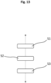
- Figure 13 shows an exemplary embodiment of a flow diagram of a method for applying or attaching the adhesive label 10 to the multi-part container 30.
- the container 30 is provided with the threaded element 31 and the container body 32 and, if appropriate, with the closure 33.
- the container 30 can be designed in a predetermined manner in accordance with the adhesive label 10 to be applied and, for example, provide a flush surface structure 37, which is advantageously designed for reliable adhesion of the adhesive label 10 (see Figure 10 ).
- This may include the material of the threaded element 31 and/or the closure 33 being a material with a high surface energy, so that a pressure-sensitive adhesive of the adhesive layer 15 of the adhesive label 10 is advantageously distributed on the outside of the threaded element 31 and/or the closure 33 and forms a reliable adhesive force.
- the surface structure 37 on the outside of the threaded element 31 and/or the closure 33 can be deliberately roughened, enabling advantageous adhesion due to the roughness.
- the adhesive label 10 is provided with the first and second label sections 11 and 21.
- the adhesive label 10 can, in particular, be provided with the adhesive layer 15 and a comb-like structure 13, which enable reliable attachment to the vessel and counteract unwanted rotation of the threaded element 31 relative to the vessel body 32.
- the adhesive label 10 can further be provided with one or more recesses 16, which take into account a corresponding surface structure 37 with elevations 34 and/or 35.
- the adhesive label 10 is attached to the vessel 30 in such a way that the first label section 11 is fastened to the threaded element 31 and, if appropriate, also to the closure 33 of the vessel 30.
- the adhesive label 10 is attached to the vessel 30 in such a way that the second label section 12 is attached to the vessel body 32 of the vessel 30.
- Steps S2 and S3 can be performed sequentially, simultaneously, or in reverse order. In each case, it is ensured that the adhesive label 10 is applied to the container 30 in such a way that it couples the threaded element 31 to the container body 32 and counteracts any movement of the threaded element 31 relative to the container body 32.
- the described adhesive label 10 enables a simple and cost-effective reliable fixation of a Luer-Lock thread on a syringe, thus counteracting any rotation of the threaded element 31 when the container 30 is opened or a syringe needle is screwed in.
- the thread is fixed to the syringe, but may not be sufficiently connected to the syringe body to withstand rotational forces.
- the force applied can be so great that the simple fixation breaks and causes the Luer-Lock thread to rotate.
- the syringe needle may also be incorrectly attached to the container 30.
- the adhesive label 10 can contribute to a stable and reliable hold of the threaded element 31 on the vessel body 32.
- the adhesive label 10 is wrapped, for example, around the syringe body 32 of the syringe 30 as well as around the Luer-Lock thread 31 and optionally also around a syringe cap or the closure 33 of the syringe 30.
- the choice of a pressure-sensitive adhesive for the adhesive layer 15 can be made, in particular, in coordination with a microscopic surface quality of the syringe body 32, the Luer-Lock thread 31 and/or the closure 33.
- the adhesive label 10 can provide further functions, such as a first-opening indicator (also electronically via an integrated RFID functionality) and protection against UV radiation, penetration or leakage. a solvent, atmospheric humidity and/or other small molecular substances.
Landscapes
- Engineering & Computer Science (AREA)
- Physics & Mathematics (AREA)
- General Physics & Mathematics (AREA)
- Theoretical Computer Science (AREA)
- Computer Security & Cryptography (AREA)
- Closures For Containers (AREA)
- Medical Preparation Storing Or Oral Administration Devices (AREA)
- Details Of Rigid Or Semi-Rigid Containers (AREA)
Description
- Die vorliegende Erfindung betrifft ein Haftetikett für ein mehrteiliges Gefäß, das auf einfache und kostengünstige Weise zu einer zuverlässigen Kopplung von Gefäßkomponenten sowie zu einem sicheren Manipulationsschutz für das Gefäß beitragen kann. Die Erfindung betrifft außerdem ein System mit einem solchen Haftetikett und einem mehrteiligen Gefäß sowie ein Verfahren zum Anbringen eines solchen Haftetiketts an einem mehrteiligen Gefäß.
- Ein Etikett kann insbesondere zur Kennzeichnung oder zum Herkunftsnachweis in Bezug auf einen zu kennzeichnenden Gegenstand dienen. Zum Beispiel werden Etiketten eingesetzt, wenn es erforderlich ist, Inhaltsstoffe eines Behälters anzugeben. Dies betrifft insbesondere Behälter im pharmazeutischen und medizinischen Bereich, deren Inhalte gegen Manipulationen geschützt werden sollen. Das Dokument
EP2014570A ist als nächstliegender Stand der Technik angesehen. - Es ist eine Aufgabe, die der Erfindung zugrunde liegt, auf einfache und kostengünstige Weise zu einem zuverlässigen Halt von Komponenten eines mehrteiligen Gefäßes beizutragen.
- Die Aufgabe wird durch ein Haftetikett, durch ein System und durch ein Verfahren zum Applizieren eines Haftetiketts mit den Merkmalen der jeweils unabhängigen Patentansprüche gelöst. Vorteilhafte Weiterbildungen des Haftetiketts, des Systems sowie des Verfahrens sind in den jeweiligen abhängigen Patentansprüchen angegeben.
- Gemäß einem Aspekt der Erfindung weist ein Haftetikett für ein mehrteiliges Gefäß mit einem Gewindeelement und einem Gefäßkörper einen ersten, flächigen Etikettenabschnitt auf, der dazu ausgebildet ist, an dem Gewindeelement des Gefäßes befestigt zu werden. Das Haftetikett weist weiter einen zweiten Etikettenabschnitt auf, der an den ersten Etikettenabschnitt angrenzt und der eine kammartige Struktur mit einer Mehrzahl von zueinander beabstandeten streifenförmigen Fixierungselementen aufweist. Der zweite Etikettenabschnitt mit den Fixierungselementen ist dazu ausgebildet, an dem Gefäßkörper des Gefäßes befestigt zu werden, sodass das Haftetikett das Gewindeelement mit dem Gefäßkörper koppelt und einer Bewegung des Gewindeelements relativ zu dem Gefäßkörper entgegenwirkt.
- Mittels des beschriebenen Haftetiketts ist eine zuverlässige und kostengünstige Fixierung eines Gewindeelements an dem zugehörigen Körper realisierbar und es kann zudem zu einem sicheren Manipulationsschutz beigetragen werden. Das Haftetikett eignet sich insbesondere für Verpackungen oder Gefäße im pharmazeutischen Bereich, wie Spritzen, Injektionsfläschchen oder Vials, die üblicherweise ein Gewindelement umfassen, das auf den zugehörigen Gefäßkörper aufgesetzt oder aufgesteckt ist.
- Das Gewindeelement umfasst dabei zum Beispiel einen Abschnitt mit einem innenliegenden Gewinde, welcher eine Art Gewindekopf ausbildet, der an einem Abschnitt angrenzt, welcher ein Aufsetzen oder Aufstecken auf den Gefäßkörper ermöglicht. Alternativ ist das Gewindeelement an seiner gesamten Außenfläche mit einem Gewinde versehen. Insbesondere ist der Gewindeabschnitt mit einem Verschluss gekoppelt, welcher eine Kappe des Gefäßes ausbildet und dieses sicher verschließt.
- Es ist eine Erkenntnis im Zusammenhang mit der vorliegenden Erfindung, dass zum Beispiel bei Glasspritzen mit einem Luer-Lock-System das Gewindeelement, welches üblicherweise aus einem Kunststoffteil gebildet und mit einem Gewindeabschnitt versehen ist, vorne auf die Glasspritze aufgesteckt wird. Die Befestigung eines solchen Kunststoffgewindeelements erfolgt durch mechanische Verzahnung oder Verklebung mit der Glasspritze. Allerdings ist eine solche Befestigung des Gewindeelements an Spritzen oft nicht ausreichend. Es kann passieren, dass beim Eindrehen einer Spritzennadel die mechanische oder klebende Kopplung nicht standhält und sich das Gewindeelement mit dreht, insbesondere wenn der Anwender das Gewindeelement beim Eindrehen der Spritzennadel nicht festhält. Auch kann es passieren, dass bei einer Verwendung hochviskoser Formulierungen, die Spritzennadel zusammen mit dem Gewindeelement abplatzt.
- Das beschriebene Haftetikett ermöglicht eine Fixierung des Gewindeelements, insbesondere in Form eines Luer-Lock-Gewindes bei Spritzen, sodass im Anwendungsfall das Luer- Lock-Gewinde ausreichend fest an der Spritze befestigt ist. Zusätzlich kann das Haftetikett, insbesondere in Abstimmung mit dem Gewindeelement, so ausgeführt sein, dass eine Erstöffnungsanzeige bereitgestellt wird. Mittels des Haftetiketts kann das Gefäß wie durch eine zweite Haut umschlossen werden, sodass das Haftetikett zusätzlich eine Schutzfunktion, wie zum Beispiel Schutz vor UV-Strahlung, für ein in dem Gefäß befindliches Medikament bieten kann.
- Gemäß einer bevorzugten Weiterbildung des Haftetiketts weisen die streifenförmigen Fixierungselemente jeweils eine vorgegebene Ausrichtung quer zu dem ersten Etikettenabschnitt auf und schließen mit einem angrenzenden Rand des ersten Etikettenabschnitts jeweils einen vorgegebenen Winkel ein. Auf diese Weise kann eine nutzbringende Überlappung von Fixierungselementen an dem Gefäß eingerichtet werden, die zu einem stabilen und zuverlässigen Halt des Gewindeelements gegen ein unerwünschtes Verdrehen beiträgt.
- Insbesondere können ein oder mehrere der Fixierungselemente mit dem angrenzenden Rand des ersten Etikettenabschnitts jeweils einen Winkel kleiner 90° oder größer 90° einschließen. Bezogen auf einen an dem Gefäß applizierten Zustand umschließen die Fixierungselemente gemäß einer solchen Ausgestaltung den Umfang des Gefäßkörpers spiralförmig und wirken einem unerwünschten Mitdrehen des Gewindeelements bei einem Öffnen des Gefäßes zuverlässig entgegen.
- Gemäß einer weiteren bevorzugten Weiterbildung des Haftetiketts schließen einige streifenförmige Fixierungselemente mit dem angrenzenden Rand des ersten Etikettenabschnitts einen Winkel kleiner 90° und weitere streifenförmige Fixierungselemente einen Winkel größer 90° ein. Gemäß einer solchen Ausgestaltung weist das Haftetikett eine kammartige Struktur mit Abschnitten auf, die aufeinander zugerichtet sind. Bezogen auf einen an dem Gefäß applizierten Zustand umschließen die jeweiligen Fixierungselemente den Umfang des Gefäßkörpers spiralförmig und kommen abschnittsweise aufeinander zu liegen. Bevorzugt sind die unterschiedlich ausgerichteten Abschnitte der kammartigen Struktur jeweils außen an gegenüberliegenden Enden des Haftetiketts ausgebildet.
- Vorzugsweise sind das Haftetikett und die Fixierungselemente so breit oder lang ausgestaltet, dass hinsichtlich des Gefäßes, das mit dem Haftetikett versehen werden soll, ein Überrundumetikett realisiert ist. Bei einem Applizieren des Haftetiketts werden der erste Etikettenabschnitt um das Gewindeelement und der zweite Etikettenabschnitt um den Gefäßkörper gewickelt, sodass die außen befindlichen Fixierungselemente sich überkreuzen und abschnittsweise bedecken. Auf diese Weise ist ein besonders stabiler Halt des Haftetiketts an dem Gefäß einrichtbar und es wird einer Relativbewegung des Gewindeelements relativ zu dem Gefäßkörper zuverlässig entgegengewirkt.
- Gemäß einer weiteren bevorzugten Ausführungsform des Haftetiketts ist der erste Etikettenabschnitt ferner dazu ausgebildet, sich bis in den Bereich eines Verschlusses des Gefäßes zu erstrecken und insbesondere an diesem befestigt zu werden, sodass das Haftetikett ferner den Verschluss mit dem Gefäßkörper koppelt. Das Haftetikett kann dabei den Verschluss mehr oder weniger berührungslos umgeben und eine Art Hülse um diesen ausbilden oder alternativ mit diesem verbunden, zum Beispiel verklebt, werden. Der erste Etikettenabschnitt des Haftetiketts ist insbesondere klebend mit dem Gewindeelement verbunden und kann zudem den Verschluss des Gefäßes hülsenartig umschließen, ohne an diesen oder mit diesem klebend gekoppelt zu sein. Der erste Etikettenabschnitt kann somit den Verschluss bezogen dessen Längsachse kontaktfrei oder klebefrei rundum umschließen. Ein oberer Teil des ersten Etikettenabschnitts bildet dann eine in Bezug auf die Längsachse nach oben offene Etikettenhülse aus. Bei einem Öffnen des Gefäßes wird dann der erste Etikettenabschnitt an eine äußere Oberfläche des Verschlusses angedrückt und mittels Ziehen und/oder Drehen von einem unteren Teil des ersten Etikettenabschnitts sowie von dem zweiten Etikettenabschnitt abgetrennt und zusammen mit dem Verschluss des Gefäßes von dem Gefäßkörper entfernt.
- Im Rahmen dieser Beschreibung beziehen sich Begriffe wie "oben" und "unten" auf eine betriebsgemäße Anordnung beziehungsweise Anwendung des Haftetiketts und des Gefäßes. Dies betrifft auch Bezeichnungen wie "Kopf" und "Körper", wobei der Kopf in der Regel oben und der Körper üblicherweise unten anzuordnen ist. Der Verschluss des Gefäßes bildet zum Beispiel als ein oberer Teil einen Kopf eines Injektionsfläschchens oder einer Spritze aus, und umfasst beispielsweise eine Kappe, einen Deckel oder einen Primärverschluss bzw. eine Primärkappe, welche zum Öffnen des Gefäßes entfernt wird.
- Der Gefäßkörper bildet dann zum Beispiel als unterer Teil einen Behälter des Injektionsfläschchens oder der Spritze zur Aufnahme und Verwahrung eines vorgegebenen Inhalts aus.
- Der erste Etikettenabschnitt des Haftetiketts ist der oberen Komponente des Gefäßes und somit dem Gewindeelement und/oder dem Verschluss zugeordnet und kann daher auch als oberer Etikettenabschnitt bezeichnet werden. Der zweite Etikettenabschnitt des Haftetiketts ist der unteren Komponente des Gefäßes zugeordnet, und verbleibt nach einem Öffnen an dem Gefäßkörper oder dem Behälter des Gefäßes und kann daher auch als unterer Etikettenabschnitt bezeichnet werden. Allerdings ist auch eine umgekehrte Ausrichtung und Verwendung des Haftetiketts möglich, bei der die Fixierungselemente an dem Gewindeelement angebracht werden und dieses mittels des ersten Etikettenabschnitts, welcher dann an dem Gefäßkörper platziert wird, in Bezug auf Relativbewegungen zu fixieren.
- Die beschriebenen Ausgestaltungen des Haftetiketts, bei denen sich der obere Etikettenabschnitt bis zu dem Verschluss des Gefäßes erstreckt, eignen sich insbesondere, um zusätzlich zu dem fixierten Halt des Gewindeelements einen Öffnungsnachweis bereitzustellen und einen Manipulationsschutz auszubilden. Bei einem Öffnen des Gefäßes wird der Verschluss von dem Gewindeelement entfernt und zum Beispiel zusammen mit einem Teilelement des ersten Etikettenabschnitts von dem verbleibenden Rest abgezogen oder abgerissen. Entsprechend ist anhand des an dem Gefäßkörper verbleibenden Teils des Haftetiketts eine erfolgte Öffnung des Gefäßes erkennbar.
- Ferner ist der erste Etikettenabschnitt vorzugsweise so ausgebildet, dass lediglich ein schmaler Spalt oder Zwischenraum zwischen dem Verschluss und dem umgebenden ersten Etikettenabschnitt vorhanden ist. Eine Manipulation oder ein Öffnungsversuch durch Eingreifen von oben in den schmalen Zwischenraum führt zu einem Einreißen oder Zerknittern des ersten Etikettenabschnitts, sodass ein solcher Vorgang erkenntliche Spuren hinterlassen würde.
- Das Haftetikett kann insbesondere als ein aufklebbares Etikett ausgebildet sein, sodass es das Gewindeelement und den Gefäßkörper bezogen auf einen Umfang teilweise oder vollständig bedeckt. Alternativ kann das Haftetikett insbesondere so ausgebildet sein, dass der erste und/oder der zweite Etikettenabschnitt in Abstimmung auf einen Umfang des Gewindeelements und/oder des Verschlusses und/oder des Gefäßkörpers des Gefäßes, das mit dem Haftetikett versehen werden soll, ausgebildet ist und eine vorgegebene Länge aufweist. Das Haftetikett kann somit teilweise oder vollständig als Rundum- oder Überrundumetikett ausgebildet sein. Zum Beispiel ist der erste Etikettenabschnitt hinsichtlich seiner Länge als Überrundumabschnitt ausgebildet, sodass er bei einem Applizieren einen Umfang des Gewindeelements vollständig umschließt und sich teilweise selbst bedeckt oder überlappt, während der zweite Etikettenabschnitt lediglich einen Teil der Außenfläche des Gefäßkörpers bedeckt und diesen nicht überrundum umschließt. Alternativ ist der zweite Etikettenabschnitt hinsichtlich seiner Länge als Überrundumabschnitt ausgebildet, sodass er bei einem Applizieren einen Umfang des Gefäßkörpers vollständig umgibt.
- Gemäß einer weiteren bevorzugten Weiterbildung des Haftetiketts ist der erste Etikettenabschnitt in Abstimmung auf eine Oberflächenstruktur des Gewindeelements und/oder des Verschlusses des Gefäßes, auf welches das Haftetikett appliziert werden soll, ausgebildet und weist eine vorgegebene Ausstanzung oder Aussparung auf. Eine solche Aussparung kann insbesondere als ausgestanzte Ausnehmung komplementär zu einer Erhebung oder einem oder mehreren vorspringenden Bereichen ausgebildet sein. Beispielsweise sind Noppen oder eine ringförmige Erhebung an dem Gewindeelement und/oder dem Verschluss des Gefäßes vorgesehen, sodass das Haftetikett angepasst an die jeweilige Oberflächenstruktur kreisförmige oder längliche bzw. ringförmige Ausnehmungen aufweist, die mit der Oberflächenstruktur korrespondieren. Falls das Gewindeelement oder der Verschluss zum Beispiel eine umlaufende Erhebung aufweist, weist das Haftetikett in Abstimmung auf eine solche Erhebung eine längliche Ausnehmung auf, die appliziert an dem Gefäß eine im Wesentlichen ringförmige Aussparung ausbildet. Das Haftetikett weist dabei zumindest einen Haltesteg, vorzugsweise zwei beabstandete Haltestege oder mehrere äquidistant angeordnete Haltestege, auf, sodass der untere, zweite Etikettenabschnitt mit dem oberen, ersten Etikettenabschnitt verbunden ist.
- Gemäß einer weiteren bevorzugten Weiterbildung des Haftetiketts ist der erste Etikettenabschnitt in Abstimmung auf eine Oberflächenstruktur des Gewindeelements und/oder des Verschlusses ausgebildet und weist eine zumindest partielle Mehrlagigkeit auf. Alternativ oder zusätzlich kann auch der zweite Etikettenabschnitt mit der kammartigen Struktur in Abstimmung auf eine Oberflächenstruktur und/oder einen Umfang des Gefäßkörpers des Gefäßes, auf das das Haftetikett angebracht werden soll, ausgebildet sein und eine zumindest partielle Mehrlagigkeit aufweisen. Das Haftetikett mit mehreren Lagen kann zum Beispiel unterschiedliche Radien oder Durchmesser eines zylindrischen Gefäßes ausgleichen, auf das das Haftetikett angebracht werden soll. Kleine Durchmesserunterschiede zwischen dem Gewindeelement und dem Gefäßkörper können bereits durch die Kammstruktur des zweiten Etikettenabschnitts auch mit nur einer Lage überwunden werden. Zudem kann eine Mehrlagigkeit zu einem Öffnungsnachweis beitragen, sodass zum Beispiel ein Abschnitt einer oberen Schicht bei einem Öffnen des gekennzeichneten Gefäßes vorgegeben abgetrennt und ein darunter liegender Bereich einer unteren Schicht gezielt freigelegt wird, um eine erfolgte Öffnung deutlich sichtbar zu kennzeichnen. Der freigelegte Abschnitt einer solchen unteren Schicht ist beispielsweise farblich markiert oder weist einen vorgegebenen Schriftzug, wie "used", "open" oder "opened", auf.
- Das Haftetikett weist bevorzugt eine Klebeschicht auf, die an einer Unterseite des ersten und/oder des zweiten Etikettenabschnitts angeordnet ist, sodass das Haftetikett mittels Kleben an dem Gefäß anordenbar ist. Auf diese Weise kann das Haftetikett kostengünstig, einfach und zuverlässig an dem dafür vorgesehenen Gefäß appliziert werden. Die Klebeschicht kann die Unterseite des Haftetiketts vollständig oder teilweise bedecken. Insbesondere kann die Klebeschicht in Abstimmung auf ein Material oder eine Oberflächenstruktur des Gewindeelements, des Verschlusses und/oder des Gefäßes vorgegeben ausgebildet sein. Ein Klebstoff der Klebeschicht ist zum Beispiel unter Berücksichtigung einer Oberflächenrauigkeit des Gewindeelements gezielt ausgewählt, um einen stabilen Halt des Haftetiketts an dem Gefäß und eine zuverlässige Fixierung des Gewindeelements einzurichten.
- Gemäß einer weiteren bevorzugten Weiterbildung weist das Haftetikett, insbesondere der erste Etikettenabschnitt einen Durchtrennungsbereich mit einem Durchtrennungselement auf, sodass bei einem Öffnen des mit dem Haftetikett applizierten Gefäßes das Haftetikett entlang des Durchtrennungsbereichs vorgegeben durchtrennbar ist, sodass zumindest ein erstes Teilelement des ersten Etikettenabschnitts zusammen mit dem Verschluss des Gefäßes von einem zweiten Teilelement des ersten Etikettenabschnitts und dem Gefäßkörper des Gefäßes entfernbar ist. Insbesondere kann das Haftetikett in dem Durchtrennungsbereich eine klebstofffreie Fläche aufweisen, sodass bei einem Öffnen des applizierten Gefäßes ein einfaches und widerstandsarmes Durchtrennen des Haftetiketts entlang des Durchtrennungselements durchführbar ist.
- Das Durchtrennungselement kann insbesondere als Perforation ausgebildet sein und ein vorgegebenes Einreißen ermöglichen. Alternativ oder zusätzlich kann das Haftetikett in dem Durchtrennungsbereich eine Folie oder ein Folienelement aufweisen, das eine relativ niedrige Einreißfestigkeit besitzt, sodass ein einfaches Einreißen und Durchtrennen des Folienelements und somit des Haftetiketts möglich ist. Ein solches Folienelement ist zum Beispiel als Acetatfolie ausgebildet und benötigt keine gesonderte Perforation oder sonstige Schwächungsstruktur, um ein einfaches Durchtrennen zu ermöglichen.
- Das Haftetikett weist zum Beispiel auch eine Klebefläche in einem oberen Bereich des ersten Etikettenabschnitts auf, der dem zweiten Etikettenabschnitt abgewandt ist. Der klebefähige Bereich des ersten Etikettenabschnitts wird dann mit einem Verschluss des Gefäßes verklebt und kann bei einem Öffnen des Gefäßes mit dem Verschluss von dem restlichen Haftetikett und dem Gewindeelement bzw. Gefäßkörper entfernt werden. Somit verbleibt kein separates Segment als Abfall zur Entsorgung.
- Sofern sich das applizierte Haftetikett bis zu einem Verschluss des Gefäßes erstreckt und der Verschluss oder das Haftetikett selbst einen Durchtrennungsbereich umfasst, weist das Haftetikett in dem Durchtrennungsbereich bevorzugt eine klebstofffreie Fläche auf. Somit ist ein einfacheres Durchtrennen des Haftetiketts und Entfernen des abtrennbaren Teils des ersten Etikettenabschnitts ermöglicht. Ein erforderlicher Kraftaufwand zum Trennen des Haftetiketts ist im Vergleich zu einem vollständig klebenden Haftetikett reduziert und eine Öffnungsdynamik des mit dem Haftetikett applizierten Gefäßes ist verbessert.
- Der jeweilige Durchtrennungsbereich kann insbesondere in Abstimmung auf das zu applizierende Gefäß in einem Bereich des Haftetiketts ausgebildet sein, welcher in einem applizierten Zustand an dem Gefäß einem Übergang zwischen dem Verschluss und dem Gewindeelement oder dem Gewindeelement und dem Gefäßkörper zugeordnet ist. Der Durchtrennungsbereich befindet sich zum Beispiel in einem Bereich eines unteren Endes des Verschlusses. Ein ausreichend kräftiges Drehen und/oder Ziehen an dem Verschluss des Gefäßes führt dann zu einer Durchtrennung des Haftetiketts. Der Durchtrennungsbereich kann aber auch in anderen Bereichen angeordnet sein, welche ein Trennen des Haftetiketts beim Öffnen des Gefäßes ermöglichen. Insbesondere wenn das Haftetikett mehrlagig ausgestaltet ist, kann der Durchtrennungsbereich zum Beispiel deutlich unterhalb des Bereichs des unteren Endes des Verschlusses eingerichtet sein, sodass eine obere oder nach außen gerichtete Lage des Haftetiketts aufgrund einer wirkenden Zug- und/oder Drehkraft vorgegeben einreißt.
- Insbesondere kann in dem Durchtrennungsbereich ein Durchtrennungselement, zum Beispiel in Form einer Perforation oder eines Aufreißstreifens, vorgesehen sein, welches ein kontrolliertes Durchtrennen des Haftetiketts ermöglicht. Zudem kann das Haftetikett, zum Beispiel in dem Bereich des ersten Etikettenabschnitts, mit vorgegebenen Oberflächeneigenschaften ausgebildet sein, die ein leichteres Öffnen des Gefäßes und Durchtrennen des Haftetiketts durch den Anwender ermöglichen. Solche nutzbringenden Oberflächeneigenschaften können zum Beispiel mit Anti-Rutsch Lacken, mittels gedruckter taktiler Elemente oder einer Oberflächenmikrostrukturierung realisiert werden, die ein sichereres Greifen des ersten Etikettenabschnitts ermöglichen.
- Gemäß einer weiteren Weiterbildung umfasst das Haftetikett ein Öffnungsnachweiselement, das in dem ersten Etikettenabschnitt integriert oder mit diesem gekoppelt ist und das dazu ausgebildet ist, ein Entfernen zumindest eines ersten Teilelements des ersten Etikettenabschnitts von dem zweiten Etikettenabschnitt und dem Gefäßkörper des Gefäßes anzuzeigen. Das Öffnungsnachweiselement kann insbesondere mit dem zuvor beschriebenen Durchtrennungselements in Form einer Perforation zusammenwirken und ein vorgegebenes Einreißen des Haftetiketts deutlich erkennbar anzeigen. Ferner kann das Öffnungsnachweiselement in Ausgestaltung einer farblichen Fläche oder eines hinterlegten Schriftzugs realisiert sein, welcher bei einem Öffnen des mit dem Haftetikett versehenen Gefäßes freigelegt wird.
- Darüber hinaus kann das Haftetikett ein elektronisches Öffnungsnachweiselement in Ausgestaltung eines RFID-Transponders umfassen, der mit dem ersten Etikettenabschnitt gekoppelt ist und der einen Chip und eine Antennenstruktur umfasst, welche mittels einer Leiterbahn mit dem Chip verbunden ist. Die Leiterbahn erstreckt sich insbesondere in den Durchtrennungsbereich und bedeckt zumindest abschnittsweise das Durchtrennungselement. Bei einem Öffnen des Gefäßes wird dann die Leiterbahn vorgegeben durchtrennt und die Unterbrechung der Leiterbahn mittels des RFID-Transponders erfasst. Eine erfolgte Öffnung des mit dem Haftetikett versehenen Gefäßes kann mittels eines Lesegerätes ausgelesen werden.
- Das beschriebene Haftetikett trägt dazu bei, dass ein Mitdrehen des Gewindeelements bei einem Öffnen des Gefäßes oder einem Anbringen einer Spritzennadel verhindert wird. Zudem kann das Haftetikett zu einem Manipulationsschutz in Bezug auf das Gefäß beitragen, wodurch zum Beispiel eine Intaktheit einer Medikamentenverpackung garantiert oder eine solche angezeigt werden kann. Mittels einer deutlich erkennbaren Anzeige einer erfolgten Erstöffnung kann das Haftetikett eine unbewusste oder unbefugte Wiederverwendung des entsprechend etikettierten Gefäßes nach dessen Gebrauch anzeigen. Somit wird mittels des Haftetiketts auch der Möglichkeit einer Manipulation des Gefäßes entgegengewirkt.
- Gemäß einem weiteren Aspekt umfasst die Erfindung eine Verwendung einer Ausgestaltung des beschriebenen Haftetiketts für ein in mehrere Teile teilbares Gefäß zur Fixierung eines Gewindeelements an einem Gefäßkörper des Gefäßes.
- Gemäß einem weiteren Aspekt der Erfindung umfasst ein System ein mehrteiliges Gefäß mit einem Gewindeelement und einem Gefäßkörper sowie ein Haftetikett, das so an dem Gefäß appliziert ist, dass ein erster Etikettenabschnitt des Haftetiketts an dem Gewindeelement befestigt ist und ein zweiter Etikettenabschnitt des Haftetiketts an dem Gefäßkörper befestigt ist, sodass das Haftetikett das Gewindeelement mit dem Gefäßkörper koppelt und einer Bewegung des Gewindeelements relativ zu dem Gefäßkörper entgegenwirkt. Das Haftetikett kann als vollflächiges Etikett ausgebildet sein, welches zur Fixierung des Gewindeelements mit diesem und mit dem Gefäßkörper verbunden ist. Darüber hinaus ist das Haftetikett des Systems vorzugsweise gemäß einer der zuvor beschriebenen Ausgestaltungen ausgebildet.
- Dadurch, dass sich die Verwendung und das System insbesondere auf eine Ausgestaltung des beschriebenen Haftetiketts beziehen oder eine solche umfassen, sind beschriebene Eigenschaften und Merkmale des Haftetiketts auch für die Verwendung und für das System offenbart und umgekehrt.
- Gemäß einer bevorzugten Weiterbildung des Systems sind der erste, flächige Etikettenabschnitt an dem Gewindeelement des Gefäßes und die streifenförmigen Fixierungselemente der kammartigen Struktur des zweiten Etikettenabschnitts an dem Gefäßkörper des Gefäßes befestigt.
- Das System kann ferner einen Verschluss aufweisen, der mit dem Gefäß gekoppelt ist, sodass das Gewindeelement zwischen dem Gefäßkörper und dem Verschluss angeordnet ist, wobei sich der erste Etikettenabschnitt dann insbesondere bis zu dem Verschluss oder bis auf den Verschluss erstreckt. Insbesondere sind das Haftetikett und das Gewindeelement und/oder der Verschluss und/oder der Gefäßkörper in Abstimmung aufeinander vorgegeben ausgebildet. Dies berücksichtigt unter anderem Geometrien, Oberflächenstrukturen und Materialien der zusammenwirkenden Komponenten.
- Gemäß einer weiteren bevorzugten Weiterbildung weist das System ein Öffnungsnachweiselement auf, das mit dem Gewindeelement und/oder dem Verschluss gekoppelt und dazu ausgebildet ist, ein Entfernen des Verschlusses von dem Gefäßkörper anzuzeigen. Ein solches Öffnungsnachweiselement des Gefäßes kann alternativ oder zusätzlich zu dem zuvor beschriebenen Öffnungsnachweiselement des Haftetiketts ausgebildet sein. Zum Beispiel ist der Verschluss mittels Verbindungsstege mit dem Gewindeelement verbunden, die bei einem Öffnen des Gefäßes aufbrechen und dadurch einen sichtbaren Nachweis für eine erfolgte Öffnung realisieren.
- Gemäß einem weiteren Aspekt der Erfindung umfasst ein Verfahren zum Anbringen eines Haftetiketts an einem mehrteiligen Gefäß mit einem Gewindeelement und einem Gefäßkörper ein Bereitstellen des Gefäßes mit dem Gewindeelement und dem Gefäßkörper und ein Bereitstellen des Haftetiketts, welches einen ersten Etikettenabschnitt und einen an den ersten Etikettenabschnitt angrenzenden zweiten Etikettenabschnitt aufweist. Das Verfahren umfasst ferner ein Anbringen des Haftetiketts an dem Gefäß derart, dass der erste Etikettenabschnitt an dem Gewindeelement des Gefäßes und der zweite Etikettenabschnitt an dem Gefäßkörper des Gefäßes befestigt wird, sodass das Haftetikett das Gewindeelement mit dem Gefäßkörper koppelt und einer Bewegung des Gewindeelements relativ zu dem Gefäßkörper entgegenwirkt.
- Das Haftetikett ist insbesondere in Form einer der zuvor beschriebenen Ausgestaltungen ausgebildet, sodass das Anbringen des Haftetiketts ein Befestigen der Fixierungselemente der kammartigen Struktur an dem Gefäßkörper des Gefäßes umfasst. Dabei werden die Fixierungselemente insbesondere spiralförmig um den Gefäßkörper gewickelt und so auf diesem befestigt, dass sie bezogen auf einen Umfang des Gefäßköpers ein Überrundumetikett ausbilden und zumindest ein Fixierungselement ein weiteres Fixierungselement abschnittsweise bedeckt.
- Mittels des beschriebenen Applizierverfahrens ist es möglich, das Haftetikett gezielt an dem Gefäß anzubringen, um einen sicheren und zuverlässigen Halt des Gewindeelements einzurichten und dieses gegen ein unerwünschtes Verdrehen relativ zu dem Gefäßkörper abzusichern oder zu fixieren. Dadurch, dass sich das Verfahren insbesondere auf ein Applizieren bzw. Anbringen einer Ausgestaltung des beschriebenen Haftetiketts bezieht, sind die beschriebenen Eigenschaften und Merkmale des Haftetiketts auch für das Verfahren offenbart und umgekehrt. Das beschriebene Haftetikett ermöglicht insbesondere auch ein nachträgliches Fixieren eines Gewindeelements relativ zu einem Gewindekörper, zum Beispiel von vorgefüllten Spritzen.
- Außerdem kann das Haftetikett einfach und kostengünstig an dem Gefäß angebracht werden und bedarf zum Beispiel keiner Temperaturbeaufschlagung, wie es bei einer Schrumpffolie der Fall ist, die zur Befestigung von Elementen um diese gestülpt und mittels Temperatureintrag geschrumpft werden. Entsprechend erfolgt dann aber auch eine Temperatureinwirkung auf den Inhalt des Gefäßes und es wird zudem ein zugehöriger Prozessabschnitt in einer Verpackungslinie benötigt. Das beschriebene Haftetikett erfordert keine Temperatureinwirkung und kann in Form einer Folie mit Haftkleber bereitgestellt sein, die einfach und zuverlässig an dem Gefäß applizierbar ist. Ein Einsatz von Schrumpffolien kann daher eingespart werden.
- Nachfolgend wird das beschriebene Haftetikett nochmal größtenteils am Beispiel eines Gefäßes einer zweiteiligen Spritze erläutert, welche insbesondere als Glasspritze oder Kunststoffspritze mit einem adaptierenden Luer-Lock-Gewinde realisiert sein kann. Die Eigenschaften und Merkmale können aber auch in Bezug auf andere mehrteilige Gefäße übertragen werden, welche ein Gewindeelement aufweisen, das als separate Komponente mit einem zugehörigen Gefäßkörper gekoppelt ist.
- Das Haftetikett weist eine spezielle Etikettenstruktur auf, bei welcher insbesondere die kammartige Struktur des zweiten Etikettenabschnitts einerseits der Überbrückung des unterschiedlichen Umfangs des Luer- Lock-Gewindes und des Spritzenkörpers und andererseits einer zuverlässigen Kraftaufnahme beim Auftreten von Drehkräften dient.
- Das Haftetikett ermöglicht eine gleichzeitige Erfassung des Spritzenmantels und der Außenseite des Luer- Lock-Gewindes sowie in verschiedenen Ausführungsformen auch ein Erfassen des Gefäßverschlusses, falls mittels des Haftetiketts auch eine Erstöffnungsanzeige erfolgen soll, und kann diesbezüglich mit einer relativ hohen Anhaftungsfestigkeit ausgebildet werden.
- Die Außenseite des Luer- Lock-Gewindes sowie optional auch die des Gefäßverschlusses sind vorzugsweise so ausgeführt, dass sie bündig mit einer Mantelfläche des Spritzenkörpers sind. Somit ist es möglich, auch ein vollflächiges Haftetikett zu verwenden, welches sowohl auf den Spritzenkörper als auch auf das Luer- Lock-Gewinde und optional auch auf den Verschluss des Gefäßes geklebt werden kann. Außerdem kann das Haftetikett auch als ein Beschriftungsetikett ausgebildet sein bzw. verwendet werden, welches zusätzlich zu der Fixierung des Luer- Lock-Gewindes optional auch eine Erstöffnungsanzeige bereitstellen kann.
- In einer weiteren bevorzugten Ausführungsform weisen die Außenseite des Luer- Lock-Gewindes sowie optional auch die Außenseite des Verschlusses eine Oberflächenstruktur auf, welche für eine Anhaftung eines mit Haftkleber ausgestatteten Haftetiketts besonders geeignet sind. Das Gewindeelement und gegebenenfalls auch der Verschluss sind insbesondere auf das anzubringende Haftetikett abgestimmt ausgebildet und umgekehrt. Das Gewindeelement und gegebenenfalls auch der Verschluss weisen zum Beispiel Oberflächenstrukturen mit makroskopischen und/oder mikroskopischen Merkmalen auf und/oder sind aus vorausgewählten Materialien gefertigt, um einen besonders stabilen Halt des Haftetiketts und eine zuverlässige Fixierung des Gewindeelements relativ zu dem Gefäßkörper einzurichten.
- Hinsichtlich makroskopischer Merkmale können die Außenseiten des Luer- Lock-Gewindes und/oder des Verschlusses mit einer relativ großen Fläche ausgestaltet sein, welche umfangsgleich mit dem Spritzenkörper ist, um eine entsprechend große Klebefläche für das Haftetikett bereitzustellen. Eine weitere Möglichkeit besteht darin, dass die Oberflächenstruktur der Außenseite des Luer- Lock-Gewindes und/oder des Verschlusses makroskopische Ausbuchtungen enthält, welche mit entsprechenden Ausstanzungen in dem Haftetikett korrespondieren. Durch solche Ausstanzungen im Haftetikett können die Ausbuchtungen an der Außenseite des Luer- Lock-Gewindes und/oder des Verschlusses durchgesteckt werden, wodurch eine mechanische Verzahnung erfolgt und zu einem besonders stabilen Halt beiträgt. Die Ausbuchtungen an der Außenseite des Luer- Lock-Gewindes und/oder des Verschlusses können beispielsweise regelmäßig oder unregelmäßig verteilte Noppen realisieren oder alternativ als durchgängige, nach außen ragende Strukturen ausgebildet sein, welche sich bezogen auf eine Längsachse der Spritze im Wesentlichen senkrecht zu dieser oder schräg zu dieser erstrecken. Solche Ausbuchtungen können zum Beispiel eine Größe von 0,5 mm bis 5 mm aufweisen. Ausbuchtungen an dem Gewindeelement und/oder dem Verschluss eines Luer-Lock-Systems können auch eine Größe in einem Bereich von 1 mm bis 2 mm aufweisen. Es ist daher nutzbringend, entsprechend große Aussparungen in dem Haftetikett vorzusehen, die auf die Abmessungen der Ausbuchtungen abgestimmt sind und vorzugsweise geringfügig größer ausgebildet sind.
- Hinsichtlich mikroskopischer Merkmale kann der jeweils für ein Anbringen des Haftetiketts vorgesehene Bereich an der Außenseite des Luer- Lock-Gewindes und/oder des Verschlusses möglichst glatt ausgeführt sein, um eine möglichst gute Anhaftung des Haftklebers des Haftetiketts zu erreichen. Bei besonders fließfähigen Klebern kann es von Vorteil sein, dass der für die Verklebung mit dem Haftetikett vorgesehene Bereich an dem Luer- Lock-Gewinde und/oder dem Verschluss eine vorgegebene Rauigkeit aufweist, wodurch insgesamt die Oberfläche und damit die Wechselwirkung mit dem Haftklebstoff erhöht werden.
- Hinsichtlich einer Materialauswahl für das Gewindeelement und/oder den Verschluss ist es zum Beispiel vorteilhaft, Kunststoffe zumindest für den äußeren für die Verklebung mit dem Haftetikett vorgesehenen Bereich mit hoher Oberflächenenergie zu wählen, wodurch eine Benetzung mit Haftkleber verbessert werden kann. Die Oberflächenenergie des Materials repräsentiert dabei ein Maß dafür, wie stark sich ein Haftkleber auf dem Material ausbreitet. Kunststoffe mit einer relativ hohen Oberflächenenergie sind zum Beispiel Polycarbonat und Polyethylenterephthalat (PET). Alternativ können Kunststoffe einer Plasma- oder Coronabehandlung unterzogen werden, um die Oberflächenenergie gezielt zu erhöhen. Zum Beispiel stellt ein Gewindeelement, welches aus Polyethylen gefertigt ist, eine relativ geringe Oberflächenenergie bereit. Geeignete Haftkleber für niederenergetische Oberflächen sind zum Beispiel Kautschuk- oder Silikonkleber. Ein Haftkleber des Haftetiketts ist daher vorzugsweise auf ein Material des Gewindeelements und/oder des Verschlusses abgestimmt oder umgekehrt.
- Zudem kann es vorteilhaft sein, das Haftetikett mit einem Haftkleber mit hoher Fließfähigkeit zu versehen, damit mögliche Unebenheiten, zum Beispiel bei relativ rauen Oberflächen des Gewindeelements und/oder des Verschlusses, vollumfänglich mit Klebstoff benetzt werden können. Besonders fließfähige Klebstoffe sind zum Beispiel modifizierte Acrylate und Synthesekautschuk.
- Außerdem kann auch der Verschluss des Gefäßes auf ein anzubringendes Haftetikett angepasst sein. Zum Beispiel kann in einem Bereich des Verschlusses eine Zweiteilung der Oberfläche vorgesehen sein. Ein unterer Teil des Verschlusses, der dem Gewindeelement zugewandt ist, ist dann zum Beispiel für eine Anhaftung des Haftetiketts gezielt ausgebildet, während der obere Teil, welcher dem Gewindeelement abgewandt ist, beispielsweise Griffhilfen, wie Riffelungen, aufweist, die eine bevorzugte Haptik zum Öffnen des Gefäßes bereitstellen.
- Zudem ist es denkbar, dass der Verschluss von außen nach innen mindestens zweilagig ausgeführt ist, wobei eine äußerste Lage für die Anhaftung des Haftetiketts vorgegeben ausgebildet ist und eine innerste Lage des Verschlusses Anforderungen an eine Primärverpackungskomponente gerecht wird.
- Das Luer- Lock-Gewinde bzw. das Gewindeelement und der Verschluss des Gefäßes können mit Haltestegen miteinander verbunden sein. Diese dienen dann zum Beispiel als ein Merkmal zur Erstöffnungsanzeige. In einem solchen Fall genügt es, wenn das Haftetikett lediglich bis zu einer Trennlinie zwischen Luer- Lock-Gewinde und dem Verschluss reichen würde bzw. entsprechend an dem Gefäß appliziert wäre, sodass das Luer- Lock-Gewindeelement an dem Spritzenkörper fixiert ist.
- Sind das Luer- Lock-Gewindeelement und der Verschluss nicht miteinander verbunden, kann das Haftetikett bis auf den Verschluss des Gefäßes reichen. Das Haftetikett weist dann zum Beispiel in dem Bereich unterhalb des Verschlusses eine Perforation sowie eine Klebstoffneutralisierung oberhalb der Perforation auf. Bei einer Drehbewegung zur Öffnung der Spritze reißt das Haftetikett entlang der Perforation ein, sodass ein oberer Teil zusammen mit dem Verschluss abgenommen werden kann.
- Durch eine zumindest partielle Doppellagigkeit des Haftetiketts kann durch das Öffnen und Abnehmen des Verschlusses und eines Etikettensegments eine Farbfläche und/oder Schriftzug freigelegt werden, wodurch eine Erstöffnung noch deutlicher anzeigbar ist. Dabei ist es zudem möglich, ein abnehmbares Teiletikett bzw. ein Teilelement gezielt abnehmbar auszubilden, welches beispielsweise für Dokumentationszwecke genutzt werden kann. Ferner ist es möglich, einen Aufreissstreifen als Öffnungsmechanismus in dem Haftetikett zu integrieren. Hierbei wird durch eine geeignete Perforation gegebenenfalls zusammen mit einer Ausbuchtung in dem Haftetikett als Anfasslasche ermöglicht, dass das Haftetikett unterhalb des Verschlusses rotativ mit dem Aufreissstreifen gezielt zerstört wird, und der Verschluss zusammen mit dem oberen Teilelement des Haftetiketts, welches oberhalb des Aufreissstreifens angeordnet war, abgenommen werden kann. Das Luer- Lock-Gewinde ist dabei stets zumindest partiell auch nach dem Entfernen des Verschlusses mit dem verbleibenden Haftetikett verklebt und dadurch mit dem Spritzenkörper verbunden, sodass das Luer- Lock-Gewinde weiterhin an der Spritze fixiert ist. Das Haftetikett kann auch so ausgebildet und an dem Gefäß appliziert sein, dass vor dem Öffnen der Spritze nur das Luer- Lock-Gewinde von dem Haftetikett erfasst und relativ zu dem Spritzenkörper fixiert ist.
- Falls der Verschluss und/oder das Luer- Lock-Gewinde nicht bündig mit dem Mantel bzw. dem Außenumfang der Spritze ausgeführt sind und ein Durchmesser des Verschlusses und/oder ein Durchmesser des Luer- Lock-Gewindes größer ist als ein Durchmesser des Spritzenkörpers, kann durch eine partielle Mehrlagigkeit des Haftetiketts eine vorhandene Stufe in einem Übergang des Verschluss zum Luer- Lock-Gewinde und/oder in einem Übergang des Luer- Lock-Gewindes zum Spritzenkörper ausgeglichen werden. Durch die Kammstruktur können aber bereits gewisse Durchmesserunterschiede überwunden werden.
- Falls eine Erstöffnungsanzeige erwünscht ist, kann dies durch optische Merkmale durch Zerstörung des Haftetiketts vorgegeben eingerichtet sein. Darüber hinaus kann eine elektronische Anzeigemöglichkeit in dem Haftetikett integriert sein. Das Haftetikett kann insbesondere ein RFID-Tag oder einen RFID-Transponder enthalten, welcher mit einer gedruckten Leiterbahn verbunden ist. Führt diese Leiterbahn über eine Trennlinie zwischen dem Verschluss und dem Gewindeelement bzw. dem Spritzenkörper, wird sie bei einem Erstöffnen der Spritze gezielt zerstört. Eine solche Unterbrechung der Leiterbahn kann mittels der RFID-Technologie erfasst und ausgelesen werden. Um eine Auslesereichweite der RFID-Funktion zu erhöhen, kann bei einem Luer- Lock-Gewinde und/oder Verschluss, die zum Beispiel umfangsgleich mit dem Spritzenkörper ausgebildet sind, der RFID-Transponder in dem Bereich des Haftetiketts integriert sein, welcher auf das Luer- Lock-Gewinde und/oder den Verschluss geklebt wird, sodass bei einem Auslesen keine nachteilige Interaktion mit dem Inhalt erfolgt, welches sich in dem Spritzenkörper befindet.
- Im Folgenden sind Ausführungsbeispiele der Erfindung anhand schematischer Zeichnungen erläutert. Es zeigen:
- Figuren 1-4
- Ausführungsbeispiele eines Haftetiketts für ein mehrteiliges Gefäß,
- Figuren 5-6
- verschiedene Ausführungsbeispiele eines Systems mit einem Haftetikett und einem Gefäß,
- Figuren 7-8
- verschiedene Ausführungsbeispiele eines Gefäßes mit einem Gewindeelement und einem Gefäßkörper,
- Figuren 9-12
- weitere Ausführungsbeispiele des Systems mit einem Haftetikett und einem Gefäß, und
- Figur 13
- ein Ablaufdiagramm für ein Verfahren zum Anbringen eines Haftetiketts an einem mehrteiligen Gefäß.
- Elemente gleicher Konstruktion und Funktion sind figurenübergreifend mit den gleichen Bezugszeichen gekennzeichnet. Aus Gründen der Übersichtlichkeit sind gegebenenfalls nicht alle dargestellten Elemente in sämtlichen Figuren mit zugehörigen Bezugszeichen gekennzeichnet.
- Die
Figuren 1-4 zeigen Ausführungsbeispiele eines Haftetiketts 10 für ein mehrteiliges Gefäß 30, welches kostengünstig herstellbar ist und eine zuverlässige Fixierung eines Gewindeelements 31 des Gefäßes 30 relativ zu einem Gefäßkörper 32 des Gefäßes 30 ermöglicht. Zudem ist mittels des Haftetiketts 10 ein zuverlässiger Erstöffnungsnachweis in Bezug auf das mit dem Haftetikett 10 versehenen Gefäß 30 realisierbar. - Das Haftetikett 10 weist einen ersten Etikettenabschnitt 11 und einen an den ersten Etikettenabschnitt 11 angrenzenden zweiten Etikettenabschnitt 12 auf. Der erste Etikettenabschnitt 11 ist dazu ausgebildet, in einem an dem Gefäß 30 applizierten Zustand an dem Gewindeelement 31 angebracht, insbesondere angeklebt zu werden. Der zweite Etikettenabschnitt 12 ist dazu ausgebildet, an dem Gefäßkörper 32 des Gefäßes 30 befestigt zu werden (s. z.B.
Figuren 5 ,6 und9 ). Die beiden Etikettenabschnitte 11 und 12 des Haftetiketts 10 bilden vorzugsweise zueinander angrenzende Teile einer gemeinsamen Materialbahn aus. - Der erste Etikettenabschnitt 11 ist flächig ausgebildet. Der zweiten Etikettenabschnitt 12 weist eine kammartige Struktur 13 mit einer Mehrzahl von streifenförmigen Fixierungselementen 131, 132 auf, die dazu ausgebildet sind, an dem Gefäßkörper 32 des Gefäßes 30 befestigt zu werden, sodass das Haftetikett 10 das Gewindeelement 31 mit dem Gefäßkörper 32 koppelt und einer Bewegung des Gewindeelements 31 relativ zu dem Gefäßkörper 32 entgegenwirkt.
- Auf diese Weise kann das Gewindeelement 31, das üblicherweise auf den Gefäßkörper 32 aufgesetzt und aufgesteckt ist, zuverlässig fixiert und gegen ein unerwünschtes Verdrehen abgesichert werden. Es ist eine Erkenntnis im Zusammenhang mit der vorliegenden Erfindung, dass eine einfache Befestigung des Gewindeelements 31, zum Beispiel an dem Gefäß 30 in Form einer Spritze oft nicht ausreichend ist. Es kann passieren, dass bei einem Eindrehen einer Spritznadel eine einfache mechanische oder klebende Kopplung zwischen dem Gewindeelement 31 und dem Spritzenkörper 32 gegebenenfalls nicht standhält und sich das Gewindeelement 31 unerwünscht mit dreht, insbesondere wenn der Anwender das Gewindeelement 31 beim Eindrehen der Spritzennadel nicht festhält.
- Die
Figuren 1 und 2 zeigen ein Ausführungsbeispiel des Haftetiketts 10 jeweils in einer schematischen Ansicht. Der zweite Etikettenabschnitt 12 weist mehrere Fixierungselemente 131 und 132 auf, die unterschiedlich ausgerichtet sind. Bezogen auf eine Längsachse LA, die auch einer Ausrichtung hinsichtlich einer Längsachse des Gefäßes 30 entspricht, auf das das Haftetikett 10 appliziert werden soll, weist der zweite Etikettenabschnitt 12 vier Fixierungselemente 131 und drei Fixierungselemente 132 auf, die aufeinander zugerichtet sind und die jeweils mit einem ihnen zugewandten Rand des ersten Etikettenabschnitts 11 einen Winkel A1 bzw. A2 einschließen. Die vier Fixierungselemente 131 sind zueinander im Wesentlichen parallel ausgerichtet. Auch die drei Fixierungselemente 132 sind zueinander im Wesentlichen parallel ausgerichtet. In alternativen Ausgestaltungen kann auch eine andere Anzahl an Fixierungselementen 131 und 132 ausgebildet sein. Es können ferner auch beidseitig gleich viele Fixierungselemente 131 und 132 ausgebildet sein oder das Haftetikett 10 weist mehr Fixierungselemente 132 und als Fixierungselemente 131 auf. - Der Winkel A1 ist insbesondere kleiner 90° ausgebildet und der Winkel A2 ist insbesondere größer 90° ausgebildet. Zum Beispiel weist der Winkel A2 einen von dem Winkel A1 abhängigen Wert auf und ist durch den Zusammenhang A2 = 180° - A1 bestimmt. Auf diese Weise sind die Fixierungselementen 131 und 132 aufeinander zu orientiert und überlappen sich an den Gefäßkörper 32 rautenförmig. Das Haftetikett 10 weist dabei eine vorgegebene Länge L auf, die insbesondere auf einen Umfang des Gefäßes 30 bzw. des Gefäßkörpers 32 und/oder des Gewindeelements 31 abgestimmt ausgebildet ist. Vorzugsweise realisiert das Haftetikett 10 ein Überrundumetikett, sodass die Länge L größer ist als der Umfang des Gewindeelements 31 und/oder des Gefäßkörpers 32.
- Besonders bevorzugt weist das Haftetikett 10 in dem Abschnitt, in dem die Fixierungselemente 131 ausgebildet sind, eine Länge L1 auf, die so ausgestaltet ist, dass sie in etwa dem Umfang des zu beklebenden Gefäßkörpers 32 entspricht. Nach dem Applizieren kommen die Fixierungselemente 132 der kammartigen Struktur 13 gekreuzt auf den Fixierungselementen 131 zu liegen oder umgekehrt. Dadurch wird die Rotation des Gewindeelements 31 besonders zuverlässig entgegengewirkt.
- In einer alternativen Ausführungsform des Haftetiketts 10 ist die Länge L in etwa gleich dem Umfang des Gefäßes 30 vorgegeben ausgebildet, sodass das Haftetikett 10 ein Rundumetikett ausbildet. Alternativ kann die Länge L des Haftetiketts 10 auch kleiner als ein Umfang des Gefäßes 30 sein, sodass das Haftetikett 10 in Bezug auf den Umfang nur einen Abschnitt einer Außenfläche des Gewindeelements 31 und/oder des Gefäßkörpers 32 bedeckt. In einer weiteren alternativen Ausführungsform können die Fixierungselemente 131 und 132 voneinander weg orientiert ausgebildet sein, sodass zum Beispiel die Fixierungselemente 131 einen Winkel A2 und die Fixierungselemente 132 einen Winkel A1 mit dem ersten Etikettenabschnitt 11 einschließen.
- Das Haftetikett 10 kann einlagig oder mehrlagig ausgebildet sein. In Bezug auf eine Höhe oder Breite kann das Haftetikett 10 das Gefäß 30 teilweise oder vollständig von unten bis oben bedecken bzw. sich von einem fußseitigen Ende des Gefäßkörpers 32 bis zu einem kopfseitigen Ende eines Verschlusses 33 des Gefäßes 30 erstrecken (s.a.
Figur 5 ). Alternativ kann sich das Haftetikett 10 auch über eine Höhe oder Breite des Gefäßes 30 hinaus erstrecken und zusätzlich zu einer Außenseite auch auf dem Verschluss 33 des Gefäßes 30 angebracht werden. - Die
Figuren 3 und 4 zeigen weitere Ausführungsbeispiele des Haftetiketts 10 in einer schematischen Ansicht, bei dem jeweils vier Fixierungselemente 131 vorgesehen sind, die im Wesentlichen gleich orientiert angeordnet sind. Zudem ist illustriert, dass das Haftetikett 10 eine Klebeschicht 15 aufweist, die eine Unterseite des Haftetiketts 10 vollständig oder teilweise bedeckt. Die Klebeschicht 15 dient insbesondere der einfachen und zuverlässigen Anbringung des Haftetiketts 10 an dem Gewindeelement 31 und dem Gefäßkörper 32. InFigur 3 weist das Haftetikett 10 eine durchgängige Klebeschicht 15 auf und bildet eine vollständig klebefähige Unterseite aus. - Gemäß dem Ausführungsbeispiel in
Figur 4 weist das Haftetikett 10 einen klebstofffreien Bereich 113 auf, der gezielt in Abstimmung auf einen Bereich ausgebildet ist, in dem ein Durchtrennungselement 14 vorgesehen ist. Das Durchtrennungselement 14 kann insbesondere in Form einer Perforation ausgestaltet sein, die ein einfaches und kontrolliertes Durchtrennen des Haftetiketts 10 ermöglicht. Ein oberes, erstes Teilelement 111 des ersten Etikettenabschnitts 11 ist vor einem Öffnen des Gefäßes 30 mit dem Verschluss 33 des Gefäßes 30 verklebt, während ein zweites, unteres Teilelement 112 an dem Gewindeelement 31 des Gefäßes 30 befestigt ist. Der klebstofffreie Bereich 113 und das Durchtrennungselement 14 sind dann einem Übergangsbereich zwischen dem Verschluss 33 und dem Gewindeelement 31 zugeordnet. Bei einem Öffnen des mit dem Haftetikett 10 applizierten Gefäßes 30 ist dieses entlang des Durchtrennungselements 14 vorgegeben durchtrennbar, sodass das erste Teilelement 111 zusammen mit dem Verschluss 33 von dem zweiten Teilelement 112 und dem Gefäßkörper 32 entfernbar ist. Ein solches entfernbares Teilelement 111 kann insbesondere auch zu Dokumentationszwecken genutzt und zum Beispiel in einer Patientenakte geklebt werden. - Die
Figuren 5 bis 6 zeigen verschiedene Ausführungsbeispiele eines Systems 1, welches das Gefäß 30 mit dem Gewindeelement 31, dem Gefäßkörper 32 und dem Verschluss 33 sowie eine Ausführungsform des Haftetiketts 10 umfasst. Der Verschluss 33 ist abdrehbar oder abziehbar mit dem Gefäßkörper 32 gekoppelt, sodass das Gewindeelement zwischen dem Verschluss 33 und dem Gefäßkörper 32 angeordnet ist. Das Gefäß 30 bzw. der Verschluss 33 und das Haftetikett 10 sind in Abstimmung aufeinander ausgebildet, sodass noppenförmige Ausbuchtungen 34 an einer Außenseite des Verschlusses 33 mittels komplementär ausgebildeten Aussparungen 16 in dem ersten Etikettenabschnitt 11 berücksichtigt werden. Entsprechendes kann analog das Gewindeelement 31 betreffen, welches Ausbuchtungen 34 aufweisen kann, die mittels des Haftetiketts 10 berücksichtigt werden, sodass zusätzlich zu einer adhäsiven Kopplung eine mechanische Verzahnung des Haftetiketts 10 mit dem Gewindeelement 31 und/oder dem Verschluss 33 einrichtbar ist. - Die Ausnehmungen oder Aussparungen 16 des Haftetiketts 10 können mittels Ausstanzen vorgegebener Geometrien ausgebildet sein. Der obere Abschnitt des Gefäßes 31, 33 kann insbesondere ein Gewinde eines Luer-Lock-Systems einer COC/COP Spritze repräsentieren. Das in
Figur 5 gezeigte Ausführungsbeispiel repräsentiert eine Möglichkeit für eine makroskopische Verzahnung des Haftetiketts 10 mit der Außenseite des Luer-Lock-Gewindes 31. - Die
Figur 6 zeigt eine weiteres Ausführungsbeispiel des Systems 1, bei dem das Gefäß 30 bzw. das Luer- Lock-Gewinde 31 und das Haftetikett 10 aufeinander abgestimmt ausgebildet sind. Der Verschluss 33 oder das Gewindeelement 31 weist eine längliche, ringförmige Wulst oder Erhebung 35 auf, die durch eine entsprechend längliche Ausnehmung 16 in dem ersten Etikettenabschnitt 11 des Haftetiketts 10 berücksichtigt ist. Der zweite Etikettenabschnitt 12 ist an dem Gefäßkörper 32 befestigt und koppelt das Gewindeelement 31 mit dem Gefäßkörper 32, sodass eine Relativbewegung der beiden Komponenten verhindert ist oder zumindest entgegengewirkt wird. Das Haftetikett 10 kann dabei vollflächig ausgeführt sein oder vorzugsweise, wie in denFiguren 1 bis 4 illustriert, eine kammartige Struktur 13 aufweisen, die den zweiten Etikettenabschnitt 12 ausbildet. - Die
Figur 7 zeigt in einer schematischen Schnittdarstellung das Gefäß 30 mit dem Verschluss 33, der mittels einer Mehrzahl von Verbindungsstegen 36 mit dem ausgesetzten oder aufgesteckten Gewindeelement 31 gekoppelt ist. Das Gewindeelement 31 ist zum Beispiel mechanisch mit dem Gefäßkörper 32 verhakt und kraft- und/oder formschlüssig gekoppelt oder alternativ oder gegebenenfalls zusätzlich mit diesem verklebt. Darüber hinaus wird das Gewindeelement 31 mittels des anzubringenden Haftetiketts 10 gegen ein unerwünschtes Verdrehen relativ zu dem Gefäßkörper 32 abgesichert. DieFigur 8 zeigt eine weitere Ausführungsform des Gefäßes 30, welches einen ähnlichen Aufbau, wie das inFigur 7 aufweist. - Die
Figur 9 illustriert schematisch das System 1, bei dem das Haftetikett 10 an dem Gefäß 30 gemäß denFiguren 7 und8 angebracht ist. DieFigur 9 zeigt zudem einen geöffneten Zustand des Gefäßes 30. Der Verschluss 33 wurde mittels Drehen und/oder Ziehen von dem Gefäßkörper 32 entfernt und das Gefäß 30 somit geöffnet. Gemäß denFiguren 7 und8 sind die Verbindungsstege 36 mittels Drehen und/oder Abziehen des Verschlusses 33 aufgebrochen und verbleiben als Teilsegmente 361 unnd 362 eines jeweiligen Verbindungsstegs 36 mit dem Verschluss 33 oder mit dem Gefäßkörper 32 gekoppelt. Die aufgebrochenen Verbindungsstege 36 bzw. die verbleibenden Teilsegmente 361 und 362 können insbesondere einen Erstöffnungsnachweis realisieren, der erkenntlich anzeigt, dass eine Erstöffnung bereits erfolgt ist. Das Haftetikett 10 kann sich gemäß einer solchen Ausgestaltung lediglich bis auf das Gewindeelement 31 und selbst keinen Durchtrennungsbereich aufweisen. Alternativ kann sich das Haftetikett 10 bis auf den Verschluss 33 erstrecken und zusätzlich einen Durchtrennungsbereich 141 aufweisen (s.Figuren 10 bis 12 ). - In
Figur 10 ist ein Ausführungsbeispiel des Systems 1 mit dem Haftetikett 10 gezeigt, welches sich bis auf den Verschluss 33 des Gefäßes 30 erstreckt und welches zwischen dem ersten und dem zweiten Etikettenabschnitt 11 und 12 den Durchtrennungsbereich 141 mit dem Durchtrennungselement 14 in Form von einer oder mehreren Perforationen aufweist. Die Perforation ermöglicht ein kontrolliertes und vorgegebenes Einreißen des Haftetiketts 10 und ist als eine gezielt ausgebildete Schwächungslinie in das Haftetikett 10 eingebracht. - Die
Figuren 11 und 12 zeigen weitere Ausführungsbeipsiele des Systems 1, welche auf einer Ausführung gemäßFigur 10 basieren können. DieFiguren 11 und 12 illustrieren jeweils einen geöffneten Zustand des Gefäßes 30, bei dem eine erfolgte Erstöffnung mittels eines Öffnungsnachweiselements 18 des Haftetiketts 10 angezeigt ist. Das Haftetikett 10 ist bei dem Öffnen des Gefäßes 30 vorgegeben durchtrennt worden, sodass das obere, erste Teilelement 111 des ersten Etikettenabschnitts 11 an dem Verschluss 33 und das untere, zweite Teilelement 112 des ersten Etikettenabschnitt 11 an dem Gewindeelement 31 des Gefäßes 30 verbleibt. Das Öffnungsnachweiselement 18 stellt in Form eines Schriftzugs einen deutlich erkennbaren Hinweis dar, dass das Gefäß 30 geöffnet ist bzw. eine Erstöffnung bereits erfolgt ist. Das Öffnungsnachweiselement 18 kann durch eine zumindest partielle Doppel- oder Mehrlagigkeit des Haftetiketts 10 bereitgestellt sein. Zum Beispiel ist der erste Etikettenabschnitt 11 doppellagig ausgestaltet und weist in dem Durchtrennungsbereich 141 auf einer unteren Etikettenschicht, die dem Gewindeelement 31 zugewandt ist, einen Schriftzug "OPEN" auf. - Das erste Teilelement 111 des ersten Etikettenabschnitts 11 erstreckt sich dann zum Beispiel auf das zweite Teilelement 112 oder zumindest auf einen Abschnitt des zweiten Teilelements 112 und bedeckt den Schriftzug in einem nicht geöffneten Zustand des Gefäßes 30 bzw. einem nicht durchtrennten Zustand des Haftetiketts 10, sodass das Öffnungsnachweiselement 18 noch nicht von außen zu sehen ist. Alternativ kann auch der erste Etikettenabschnitt 11 als abtrennbar von dem zweiten Etikettenabschnitt 12 ausgebildet sein, sodass der erste Etikettenabschnitt 11 einen Teil des zweiten Etikettenabschnitts 12 bedeckt und in dem Bereich des Öffnungsnachweiselements 18 eine Doppellagigkeit gegeben ist. Bei einem Öffnen wird das erste Teilelement 111 oder der erste Etikettenabschnitt 11 zusammen mit dem Verschluss 33 entfernt. Somit wird der Überlappbereich zwischen dem ersten und dem zweiten Teilelement 111 und 112 oder zwischen dem ersten und dem zweiten Etikettenabschnitt 11 und 12 getrennt und das Öffnungsnachweiselement 18 freigelegt.
-
Figur 12 zeigt eine weitere Ausführungsform des Haftetiketts 10, in welcher das Öffnungsnachweiselement 18 ein erstes Teilelement 181 und ein zweites Teilelement 182 aufweist. Das erste Teilelement 181 kann als verlängerter Abschnitt des ersten Etikettenabschnitts 11 oder des oberen, ersten Teilelements 111 ausgebildet sein, welcher das zweite Teilelement 182 in einem nicht geöffneten Zustand des Gefäßes 30 bedeckt. Das Haftetikett 10 weist zum Beispiel im Bereich des Öffnungselements 18 eine Perforation auf, die vorgegeben einreißt, wenn das Gefäß 30 geöffnet und der Verschluss 33 entfernt wird. Auf diese Weise wird das zweite Teilelement 182 freigelegt, welches beispielsweise als eine deutlich erkennbare farbige Fläche ausgestaltet ist. Insbesondere die farbige Fläche des zweiten Teilelements 182 dient als Erstöffnungshinweis, aber auch das von dem ersten Teilelement 111 des ersten Etikettenabschnitt 11 abstehende erste Teilelement 181 des Öffnungsnachweiselements 18 bildet als Etikettenfahne einen erkennbaren Erstöffnungshinweis. -
Figur 13 zeigt ein Ausführungsbeispiel für ein Ablaufdiagramm eines Verfahrens zum Applizieren bzw. Anbringen des Haftetiketts 10 an dem mehrteiligen Gefäß 30. In einem Schritt S1 wird das Gefäß 30 mit dem Gewindeelement 31 und dem Gefäßkörper 32 und gegebenenfalls mit dem Verschluss 33 bereitgestellt. Das Gefäß 30 kann dabei in Abstimmung auf das anzubringende Haftetikett 10 vorgegeben ausgebildet sein und zum Beispiel eine bündige Oberflächenstruktur 37 bereitstellen, die nutzbringend für ein zuverlässiges Ankleben des Haftetiketts 10 ausgebildet ist (s.Figur 10 ). - Dies kann beinhalten, dass das Material des Gewindeelements 31 und/oder des Verschlusses 33 ein Material mit einer hohen Oberflächenenergie ist, sodass sich ein Haftkleber der Klebeschicht 15 des Haftetiketts 10 nutzbringend auf der Außenseite des Gewindeelements 31 und/oder des Verschlusses 33 verteilt und eine zuverlässige Haftkraft ausbildet. Alternativ oder zusätzlich kann die Oberflächenstruktur 37 an der Außenseite des Gewindeelements 31 und/oder des Verschluss 33 gezielt aufgeraut werden und aufgrund der Rauigkeit ein vorteilhaftes Ankleben ermöglichen.
- Außerdem erfolgt ein Bereitstellen des Haftetiketts 10 mit dem ersten und dem zweiten Etikettenabschnitt 11 und 21. Das Haftetikett 10 kann insbesondere mit der Klebeschicht 15 und einer kammartigen Struktur 13 bereitgestellt werden, die ein zuverlässiges Anbringen an dem Gefäß ermöglichen und einer unerwünschten Rotation des Gewindeelements 31 relativ zu dem Gefäßkörper 32 entgegenwirken. Das Haftetikett 10 kann ferner mit einer oder mehreren Ausnehmungen 16 bereitgestellt sein, die eine entsprechende Oberflächenstruktur 37 mit Erhebungen 34 und/oder 35 berücksichtigt.
- In einem weiteren Schritt S2 erfolgt ein Anbringen des Haftetiketts 10 an dem Gefäß 30 derart, dass der erste Etikettenabschnitt 11 an dem Gewindeelement 31 und gegebenenfalls auch an dem Verschluss 33 des Gefäßes 30 befestigt wird.
- In einem weiteren Schritt S3 erfolgt ein Anbringen des Haftetiketts 10 an dem Gefäß 30 derart, dass der zweite Etikettenabschnitt 12 an dem Gefäßkörper 32 des Gefäßes 30 befestigt wird.
- Die Schritte S2 und S3 können nacheinander, gleichzeitig oder in umgekehrter Reihenfolge durchgeführt werden. Dabei ist jeweils sichergestellt, dass Haftetikett 10 derart an dem Gefäß 30 appliziert ist, dass es das Gewindeelement 31 mit dem Gefäßkörper 32 koppelt und einer Bewegung des Gewindeelements 31 relativ zu dem Gefäßkörper 32 entgegenwirkt.
- Das beschriebene Haftetikett 10 ermöglicht auf einfache und kostengünstige Weise eine zuverlässige Fixierung eines Luer-Lock-Gewindes einer Spritze, sodass einem Mitdrehen des Gewindeelements 31 bei einem Öffnen des Gefäßes 30 oder einem Eindrehen einer Spritzennadel entgegengewirkt wird. Dies betrifft insbesondere Spritzen, die aus Glas oder Kunststoff bestehen und ein Luer-Lock-Gewinde aus Kunststoff aufweisen. Das Gewinde ist dabei an der Spritze fixiert, gegebenenfalls jedoch nicht ausreichend mit dem Spritzenkörper verbunden, um Drehkräften standhalten zu können. Bei einer Verbindung des Luer-Lock-Gewindes mit einer Spritzennadel kann die Krafteinwirkung so groß sein, dass die einfache Fixierung bricht und ein Durchdrehen des Luer-Lock-Gewindes bedingt. Infolgedessen kann ferner ein fehlerhaftes Anbringen der Spritzennadel an dem Gefäß 30 erfolgen.
- Mittels des Haftetiketts 10 kann zu einem stabilen und zuverlässigen Halt des Gewindeelements 31 an dem Gefäßkörper 32 beigetragen werden. Das Haftetikett 10 wird zum Beispiel um den Spritzenkörper 32 der Spritze 30 sowie um Luer-Lock-Gewinde 31 und optional auch um eine Spritzenkappe bzw. den Verschluss 33 der Spritze 30 gewickelt. Eine Wahl eines Haftklebstoffes der Klebeschicht 15 kann insbesondere in Abstimmung auf eine mikroskopische Oberflächenbeschaffenheit des Spritzenkörpers 32, des Luer-Lock-Gewindes 31 und/oder des Verschlusses 33 getroffen sein. Zusätzlich zu der Fixierung des Gewindeelements 31 können mittels des Haftetiketts 10 weitere Funktionen, wie zum Beispiel eine Erstöffnungsanzeige (auch elektronisch mittels einer integrierten RFID-Funktionalität) und ein Schutz vor UV-Strahlung, vor Eindringen oder Austreten eines Lösungsmittels, von Luftfeuchtigkeit und/oder anderen kleinmolekularen Stoffen, bereitgestellt werden.
-
- 1
- System
- 10
- Haftetikett
- 11
- erster Etikettenabschnitt
- 111
- erstes Teilelement des ersten Etikettenabschnitts
- 112
- zweites Teilelement des ersten Etikettenabschnitts
- 113
- klebstofffreier Teil des Etikettenabschnitts
- 12
- zweiter Etikettenabschnitt
- 13
- Kammstruktur
- 131
- Fixierungselemente
- 132
- Fixierungselemente
- 14
- Durchtrennungselement / Perforation / Folienelement
- 141
- Durchtrennungsbereich
- 15
- Klebstofffläche
- 16
- Ausnehmung
- 18
- Öffnungsnachweiselement
- 181
- erstes Teilelement des Öffnungsnachweiselements
- 182
- zweites Teilelement des Öffnungsnachweiselements
- 30
- Gefäß / Spritze
- 31
- Gewindeelement / Luer- Lock-Gewinde
- 32
- Gefäßkörper / Spritzenkörper
- 33
- Verschluss
- 34
- Erhebung
- 35
- Erhebung
- 36
- Verbindungsstege zwischen dem Verschluss und dem Gewindeelement
- 361
- Teilsegment des Verbindungsstegs
- 362
- Teilsegment des Verbindungsstegs
- 37
- Oberflächenstruktur des Gewindeelements / des Verschlusses
- A1
- erster Winkel
- A2
- zweiter Winkel
- L
- Länge des Haftetiketts
- L1
- Länge eines Abschnitts des Haftetiketts
- LA
- Längsachse
- S(i)
- Schritt eines Verfahrens zum Anbringen eines Haftetiketts
Claims (15)
- Haftetikett (10) für ein mehrteiliges Gefäß (30) mit einem Gewindeelement (31) und einem Gefäßkörper (32), aufweisend:- einen ersten, flächigen Etikettenabschnitt (11), der dazu ausgebildet ist, an dem Gewindeelement (31) des Gefäßes (30) befestigt zu werden, und- einen zweiten Etikettenabschnitt (12), der an den ersten Etikettenabschnitt (11) angrenzt und der eine kammartige Struktur (13) mit einer Mehrzahl von zueinander beabstandeten streifenförmigen Fixierungselementen (131, 132) aufweist, die dazu ausgebildet sind, an dem Gefäßkörper (32) des Gefäßes (30) befestigt zu werden, sodass das Haftetikett (10) das Gewindeelement (31) mit dem Gefäßkörper (32) koppelt und einer Bewegung des Gewindeelements (31) relativ zu dem Gefäßkörper (32) entgegenwirkt.
- Haftetikett (10) nach Anspruch 1, bei dem die streifenförmigen Fixierungselemente (131, 132) jeweils eine vorgegebene Ausrichtung quer zu dem ersten Etikettenabschnitt (11) aufweisen und mit einem angrenzenden Rand des ersten Etikettenabschnitts (11) jeweils einen vorgegebenen Winkel (A1, A2) einschließen.
- Haftetikett (10) nach Anspruch 2, bei dem ein oder mehrere streifenförmige Fixierungselemente (131) mit dem angrenzenden Rand des ersten Etikettenabschnitts (11) jeweils einen Winkel (A1) kleiner 90° und/oder ein oder mehrere streifenförmige Fixierungselemente (132) mit dem angrenzenden Rand des ersten Etikettenabschnitts (11) jeweils einen Winkel (A2) größer 90° einschließen.
- Haftetikett (10) nach einem der Ansprüche 1 bis 3, bei dem der erste Etikettenabschnitt (11) ferner dazu ausgebildet ist, an einem Verschluss (33) des Gefäßes (30) befestigt zu werden, sodass das Haftetikett (10) den Verschluss (33) mit dem Gefäßkörper (32) koppelt.
- Haftetikett (10) nach einem der Ansprüche 1 bis 4, bei dem der erste Etikettenabschnitt (11) in Abstimmung auf eine Oberflächenstruktur (37) des Gewindeelements (31) und/oder des Verschlusses (33) ausgebildet ist und eine vorgegebene Ausstanzung oder Aussparung (16) und/oder eine zumindest partielle Mehrlagigkeit aufweist.
- Haftetikett (10) nach einem der Ansprüche 1 bis 5, aufweisend:
eine Klebeschicht (15), die an einer Unterseite des ersten und/oder des zweiten Etikettenabschnitts (11, 12) angeordnet ist, sodass das Haftetikett (10) mittels Kleben an dem Gefäß (30) anordenbar ist, wobei die Klebeschicht (15) in Abstimmung auf ein Material oder eine Oberflächenstruktur (37) des Gewindeelements (31) und/oder des Gefäßkörpers (32) und/oder des Verschlusses (33) vorgegeben ausgebildet ist. - Haftetikett (10) nach einem der Ansprüche 1 bis 6, bei dem der erste Etikettenabschnitt (11) ein Durchtrennungselement (14) aufweist, sodass bei einem Öffnen des mit dem Haftetikett (10) applizierten Gefäßes (30) das Haftetikett (11) entlang des Durchtrennungselements (14) vorgegeben durchtrennbar ist und zumindest ein erstes Teilelement (111) des ersten Etikettenabschnitts (11) zusammen mit dem Verschluss (33) des Gefäßes (30) von einem zweiten Teilelement (112) des ersten Etikettenabschnitts (11) und dem Gefäßkörper (32) des Gefäßes (30) entfernbar ist.
- Haftetikett (10) nach Anspruch 7 in Verbindung mit Anspruch 6, bei dem das Haftetikett (10) in einem Bereich des Durchtrennungselements (14) eine klebstofffreie Fläche aufweist.
- Haftetikett (10) nach einem der Ansprüche 7 bis 8, aufweisend:
einen RFID-Transponder, der mit dem ersten Etikettenabschnitt (11) gekoppelt ist und der einen Chip und eine Antennenstruktur umfasst, welche mittels einer Leiterbahn mit dem Chip verbunden ist, wobei die Leiterbahn das Durchtrennungselement (14) zumindest abschnittsweise bedeckt. - System (1), aufweisend:- eine mehrteilige Spritze (30) mit einem Gewindeelement (31) zur Aufnahme einer Spritzennadel und einem Spritzenkörper (32), und- ein Haftetikett (10), das so an der Spritze (30) appliziert ist, dass ein erster Etikettenabschnitt (11) des Haftetiketts (10) an dem Gewindeelement (31) befestigt ist und ein zweiter Etikettenabschnitt (12) des Haftetiketts (10) an dem Spritzenkörper (32) befestigt ist, sodass das Haftetikett (10) das Gewindeelement (31) mit dem Spritzenkörper (32) koppelt und einer Bewegung des Gewindeelements (31) relativ zu dem Spritzenkörper (32) entgegenwirkt.
- System (1) nach Anspruch 10, bei dem das Haftetikett (10) nach einem der Ansprüche 1 bis 9 ausgebildet ist, sodass der erste, flächige Etikettenabschnitt (11) an dem Gewindeelement (31) der Spritze (30) befestigt ist und die streifenförmigen Fixierungselemente (131, 132) der kammartigen Struktur (13) des zweiten Etikettenabschnitts (12) an dem Spritzenkörper (32) der Spritze (30) befestigt sind.
- System (1) nach Anspruch 10 oder 11, bei dem die Spritze (30) ferner einen Verschluss (33) aufweist, der mit dem Spritzenkörper (32) gekoppelt ist, sodass das Gewindeelement (31) zwischen dem Spritzenkörper (32) und dem Verschluss (33) angeordnet ist, wobei sich der erste Etikettenabschnitt (11) bis zu dem Verschluss (33) erstreckt.
- System (1) nach einem der Ansprüche 10 bis 12, aufweisend:- einen Verschluss (33), der mit dem Spritzenkörper (32) gekoppelt ist, sodass das Gewindeelement (31) zwischen dem Spritzenkörper (32) und dem Verschluss (33) angeordnet ist, und- ein Öffnungsnachweiselement (36, 361, 362), das mit dem Gewindeelement (31) und/oder dem Verschluss (33) gekoppelt und dazu ausgebildet ist, ein Entfernen des Verschlusses (33) von dem Spritzenkörper (32) anzuzeigen.
- Verfahren zum Applizieren eines Haftetiketts (10) an einer mehrteiligen Spritze (30) mit einem Gewindeelement (31) zur Aufnahme einer Spritzennadel und einem Spritzenkörper (32), umfassend:- Bereitstellen der Spritze (30) mit dem Gewindeelement (31) und dem Spritzenkörper (32),- Bereitstellen des Haftetiketts (10), welches einen ersten Etikettenabschnitt (11) und einen an den ersten Etikettenabschnitt (11) angrenzenden zweiten Etikettenabschnitt (12) aufweist, und- Anbringen des Haftetiketts (10) an der Spritze (30) mittels Befestigen des ersten Etikettenabschnitts (11) an dem Gewindeelement (31) der Spritze (30) und Befestigen des zweiten Etikettenabschnitts (12) an dem Spritzenkörper (32) der Spritze (30), sodass das Haftetikett (10) das Gewindeelement (31) mit dem Spritzenkörper (32) koppelt und einer Bewegung des Gewindeelements (31) relativ zu dem Spritzenkörper (32) entgegenwirkt.
- Verfahren nach Anspruch 14, bei dem der erste Etikettenabschnitt (11) des Haftetiketts (10) flächig ausgebildet ist, und der zweite Etikettenabschnitt (12) des Haftetiketts (10) eine kammartige Struktur (13) mit einer Mehrzahl von streifenförmigen Fixierungselementen (131, 132) aufweist, und bei dem das Anbringen des Haftetiketts (10) an der Spritze (30) umfasst:
Befestigen der Fixierungselemente (131, 132) an dem Spritzenkörper (32) der Spritze (30), sodass sie bezogen auf einen Umfang des Spritzenkörpers (32) ein Überrundumetikett ausbilden und zumindest ein Fixierungselement (131, 132) ein weiteres Fixierungselement (131, 132) abschnittsweise bedeckt.
Priority Applications (1)
| Application Number | Priority Date | Filing Date | Title |
|---|---|---|---|
| EP22199776.0A EP4152300A1 (de) | 2019-12-18 | 2020-11-12 | System mit einer spritze und einem haftetikett |
Applications Claiming Priority (2)
| Application Number | Priority Date | Filing Date | Title |
|---|---|---|---|
| DE102019134927.3A DE102019134927A1 (de) | 2019-12-18 | 2019-12-18 | Haftetikett für ein mehrteiliges Gefäß, System und Verfahren zum Applizieren eines Haftetiketts an einem mehrteiligen Gefäß |
| PCT/EP2020/081865 WO2021121796A1 (de) | 2019-12-18 | 2020-11-12 | HAFTETIKETT FÜR EIN MEHRTEILIGES GEFÄß, SYSTEM UND VERFAHREN ZUM APPLIZIEREN EINES HAFTETIKETTS AN EINEM MEHRTEILIGEN GEFÄß |
Related Child Applications (2)
| Application Number | Title | Priority Date | Filing Date |
|---|---|---|---|
| EP22199776.0A Division-Into EP4152300A1 (de) | 2019-12-18 | 2020-11-12 | System mit einer spritze und einem haftetikett |
| EP22199776.0A Division EP4152300A1 (de) | 2019-12-18 | 2020-11-12 | System mit einer spritze und einem haftetikett |
Publications (2)
| Publication Number | Publication Date |
|---|---|
| EP4078562A1 EP4078562A1 (de) | 2022-10-26 |
| EP4078562B1 true EP4078562B1 (de) | 2025-03-26 |
Family
ID=73452173
Family Applications (2)
| Application Number | Title | Priority Date | Filing Date |
|---|---|---|---|
| EP22199776.0A Pending EP4152300A1 (de) | 2019-12-18 | 2020-11-12 | System mit einer spritze und einem haftetikett |
| EP20807690.1A Active EP4078562B1 (de) | 2019-12-18 | 2020-11-12 | Haftetikett für ein mehrteiliges gefäss, system und verfahren zum applizieren eines haftetiketts an einem mehrteiligen gefäss |
Family Applications Before (1)
| Application Number | Title | Priority Date | Filing Date |
|---|---|---|---|
| EP22199776.0A Pending EP4152300A1 (de) | 2019-12-18 | 2020-11-12 | System mit einer spritze und einem haftetikett |
Country Status (4)
| Country | Link |
|---|---|
| US (4) | US12125416B2 (de) |
| EP (2) | EP4152300A1 (de) |
| DE (1) | DE102019134927A1 (de) |
| WO (1) | WO2021121796A1 (de) |
Families Citing this family (4)
| Publication number | Priority date | Publication date | Assignee | Title |
|---|---|---|---|---|
| AU2021372248A1 (en) | 2020-11-02 | 2022-12-01 | Becton Dickinson France | Radio frequency identification (RFID) inlays for use with medical injection devices |
| DE102022116021A1 (de) * | 2022-06-28 | 2023-12-28 | Schreiner Group Gmbh & Co. Kg | Multifunktionsetikett, System und Verfahren zum Herstellen eines Multifunktionsetiketts |
| DE102023113995A1 (de) * | 2023-05-26 | 2024-11-28 | Schreiner Group Gmbh & Co. Kg | Schutzetikett für ein Gefäß, System und Verfahren |
| DE102023129196A1 (de) * | 2023-10-24 | 2025-04-24 | Schreiner Group Gmbh & Co. Kg | Überrundumetikett, System und Verfahren zum Applizieren eines Überrundumetiketts an einem Gefäß |
Family Cites Families (37)
| Publication number | Priority date | Publication date | Assignee | Title |
|---|---|---|---|---|
| US3523623A (en) * | 1968-09-20 | 1970-08-11 | Zapata Industries Inc | Cover for cut edge projections of twist-off crowns for protecting the fingers of the user |
| US4540101A (en) * | 1983-10-26 | 1985-09-10 | Aluminum Company Of America | Container assembly including a tamper-indicating band |
| US5048711A (en) * | 1990-06-28 | 1991-09-17 | Sage Products, Inc. | Label indicator for screw thread closure and method of use |
| US5135510A (en) * | 1991-04-19 | 1992-08-04 | Maszkiewicz Mark E | Hypodermic syringe |
| JP3187139B2 (ja) | 1992-05-26 | 2001-07-11 | 日本エステル株式会社 | 熱伸長性ポリエステル繊維の製造法 |
| US5727819A (en) | 1996-05-31 | 1998-03-17 | Pharmagraphics L.L.C, Midwest | Resealable laminated package label having tamper resistant feature |
| JP3767712B2 (ja) | 1997-03-10 | 2006-04-19 | 大日本住友製薬株式会社 | 改ざん防止ラベル |
| US6146729A (en) * | 1998-04-30 | 2000-11-14 | Nihda; Christopher J. P. | Film seal |
| US6276725B1 (en) | 1999-04-09 | 2001-08-21 | The Standard Register Company | Automation friendly security labels for specimen container |
| EP1044698A1 (de) | 1999-04-14 | 2000-10-18 | Amgen Inc., | Vorgefüllte Spritze mit Originalitätssicherung |
| US6908113B2 (en) * | 2001-08-15 | 2005-06-21 | Laboratories Merck Sharp And Dohme-Chibret, Snc | Tamper-evident label |
| MXPA05004446A (es) * | 2002-10-25 | 2005-07-26 | Nat Label Co | Aparato de etiquetado y metodo para hacer el mismo. |
| GB0228515D0 (en) | 2002-12-06 | 2003-01-15 | Parker David W | Improvements in or relating to retracting needle safety syringes |
| JP2007522501A (ja) * | 2004-02-18 | 2007-08-09 | シュライナー グループ ジーエムビエイチ アンド カンパニー ケージー | 軸方向に異なる横断面間の変わり目を封印するためのラベル |
| ATE349054T1 (de) * | 2004-02-18 | 2007-01-15 | Schreiner Group Gmbh & Co Kg | Etikett und mit dem eitkett übersiegelte anordnung zweier körper |
| JP4646658B2 (ja) | 2004-03-29 | 2011-03-09 | 株式会社ジェイ・エム・エス | プレフィルドシリンジ |
| EP1807797B1 (de) | 2004-10-28 | 2016-12-21 | Assa Abloy Ab | Sicherheits-versiegelungseinrichtung mit einem rfid-etikett |
| US7255689B2 (en) | 2004-10-29 | 2007-08-14 | Safety Syringes, Inc. | Syringe with anti-rotation for luer lock |
| EP1836048B1 (de) | 2005-01-10 | 2013-09-25 | Avery Dennison Corporation | Entfernbare kräuseletiketten |
| JP2007079433A (ja) | 2005-09-16 | 2007-03-29 | Ajinomoto Co Inc | 糊付きラベル |
| DE102006025335A1 (de) | 2006-05-31 | 2007-12-06 | Tesa Scribos Gmbh | Etikett mit einem Sicherheitsmerkmal und Behälter mit einem Etikett |
| JP4960676B2 (ja) * | 2006-09-13 | 2012-06-27 | テルモ株式会社 | プレフィルドシリンジ |
| US20080308444A1 (en) * | 2007-06-13 | 2008-12-18 | Baxter International Inc. | Packaging system and method of alerting a practitioner |
| US20080308443A1 (en) * | 2007-06-13 | 2008-12-18 | Baxter International Inc. | Packaging system and method of use |
| US20100305506A1 (en) | 2008-01-18 | 2010-12-02 | Fahrer Theodore J | Method for Correcting Medical Fluid Injection Pressures Based on Usage |
| JP5430199B2 (ja) * | 2009-03-31 | 2014-02-26 | テルモ株式会社 | 医療用具 |
| DE102011055389B4 (de) | 2011-11-15 | 2014-05-22 | Gerresheimer Regensburg Gmbh | Glasspritzenseitiges Montagehilfselement, Verfahren zum Befestigen eines glasspritzenseitigen Montagehilfselements und Verfahren zum Herstellen eines glasspritzenseitigen Montagehilfselements sowie Anordnung aus einer Glasspritze und aus einem Montagehilfselement |
| US9318473B2 (en) * | 2012-04-20 | 2016-04-19 | Infineon Technologies Ag | Semiconductor device including a polymer disposed on a carrier |
| WO2013167701A1 (de) | 2012-05-09 | 2013-11-14 | Schreiner Group Gmbh & Co. Kg | Verschlusselement für ein gefäss |
| JP6069027B2 (ja) | 2013-02-27 | 2017-01-25 | 株式会社岩田レーベル | シリンジ用ラベル及びそれを用いた薬液充填シリンジ |
| JP6396204B2 (ja) | 2014-12-25 | 2018-09-26 | 株式会社フジシール | プレフィルドシリンジ及びプレフィルドシリンジ用の熱収縮性ラベル |
| JP2016190663A (ja) | 2015-03-31 | 2016-11-10 | 株式会社フジシールインターナショナル | ラベル付き容器及び熱収縮性ラベル |
| US12403262B2 (en) * | 2018-11-28 | 2025-09-02 | Fresenius Kabi Usa, Llc | Tamper evident assembly with RFID for syringes |
| US10661030B1 (en) | 2018-11-28 | 2020-05-26 | Fresenius Kabi Usa, Llc | Tamper evident cap for syringes |
| DE102020101702A1 (de) * | 2020-01-24 | 2021-07-29 | Schreiner Group Gmbh & Co. Kg | Etikettieranordnung für ein mehrteiliges Gefäß, System und Verfahren zum Anbringen einer Etikettieranordnung an einem mehrteiligen Gefäß |
| US20230146326A1 (en) * | 2020-02-26 | 2023-05-11 | Avery Dennison Retail Information Services Llc | Rfid security label for packaging |
| DE102020133546A1 (de) * | 2020-12-15 | 2022-06-15 | Schreiner Group Gmbh & Co. Kg | Elektronische Etikettieranordnung für ein mehrteiliges Gefäß, System und Verfahren zum Anbringen einer elektronischen Etikettieranordnung an einem mehrteiligen Gefäß |
-
2019
- 2019-12-18 DE DE102019134927.3A patent/DE102019134927A1/de active Pending
-
2020
- 2020-11-12 WO PCT/EP2020/081865 patent/WO2021121796A1/de not_active Ceased
- 2020-11-12 EP EP22199776.0A patent/EP4152300A1/de active Pending
- 2020-11-12 EP EP20807690.1A patent/EP4078562B1/de active Active
- 2020-11-12 US US17/786,618 patent/US12125416B2/en active Active
-
2022
- 2022-10-05 US US17/960,308 patent/US12027074B2/en active Active
-
2023
- 2023-05-23 US US18/200,819 patent/US12230167B2/en active Active
-
2025
- 2025-01-14 US US19/019,901 patent/US20250157362A1/en active Pending
Also Published As
| Publication number | Publication date |
|---|---|
| EP4078562A1 (de) | 2022-10-26 |
| US12027074B2 (en) | 2024-07-02 |
| US20230298486A1 (en) | 2023-09-21 |
| WO2021121796A1 (de) | 2021-06-24 |
| US20250157362A1 (en) | 2025-05-15 |
| US12125416B2 (en) | 2024-10-22 |
| EP4152300A1 (de) | 2023-03-22 |
| US12230167B2 (en) | 2025-02-18 |
| DE102019134927A1 (de) | 2021-06-24 |
| US20230021381A1 (en) | 2023-01-26 |
| US20230023532A1 (en) | 2023-01-26 |
Similar Documents
| Publication | Publication Date | Title |
|---|---|---|
| EP4078562A1 (de) | HAFTETIKETT FÜR EIN MEHRTEILIGES GEFÄß, SYSTEM UND VERFAHREN ZUM APPLIZIEREN EINES HAFTETIKETTS AN EINEM MEHRTEILIGEN GEFÄß | |
| EP2720958B1 (de) | Verschlusssiegel | |
| EP2847082B1 (de) | Verschlusselement für ein gefäss | |
| EP1536397B1 (de) | Etikett, Spritzenkörper und Spritzenanordnung mit Etikett | |
| WO2020069924A1 (de) | SICHERHEITSETIKETT FÜR EIN MEHRTEILIGES GEFÄß, VERWENDEN EINES SICHERHEITSETIKETTS, SYSTEM UND VERFAHREN ZUM APPLIZIEREN EINES SICHERHEITSETIKETTS FÜR EIN MEHRTEILIGES GEFÄß | |
| WO2022128893A1 (de) | Elektronische etikettieranordnung für ein mehrteiliges gefäss, system und verfahren zum anbringen einer elektronischen etikettieranordnung an einem mehrteiligen gefäss | |
| EP3175439B1 (de) | Etikett für einen mehrteiligen oder in mehrere teile teilbaren behälter | |
| WO2024160624A1 (de) | ETIKETT, SYSTEM UND VERFAHREN ZUM APPLIZIEREN EINES ETIKETTS AN EINEM MEHRTEILIGEN GEFÄß | |
| EP3898447B1 (de) | Etikettieranordnung für ein mehrteiliges gefäss, system und verfahren zum anbringen einer etikettieranordnung an einem mehrteiligen gefäss | |
| WO2024231280A1 (de) | ETIKETT FÜR EIN GEFÄß UND SYSTEM | |
| EP4093682B1 (de) | Etikettieranordnung für ein mehrteiliges gefäss, system und verfahren zum anbringen einer etikettieranordnung an einem mehrteiligen gefäss | |
| EP4300469A1 (de) | Multifunktionsetikett, system und verfahren zum herstellen eines multifunktionsetiketts | |
| EP2521114B1 (de) | Aufhängeetikett für einen Flüssigkeitsbeutel und Verfahren zum Anbringen eines Etiketts an einem mit Flüssigkeit gefüllten Beutel | |
| EP0601283B1 (de) | Verschluss für eine Medikamentenflasche | |
| DE102022131253A1 (de) | Etikettieranordnung für ein mehrteiliges Gefäß, System und Verfahren zum Anbringen einer Etikettieranordnung an einem mehrteiligen Gefäß | |
| DE102021122650A1 (de) | Etikettieranordnung und Verfahren zum Herstellen einer Etikettieranordnung für eine Spritze und Spritzensystem | |
| DE102024121216A1 (de) | Etikett, System und Verfahren zum Entfernen eines applizierten Etiketts | |
| DE102015009702B3 (de) | Getränkedose mit Schutzfolienlagerraum | |
| DE102011111921A1 (de) | Ampullenschutzetikett | |
| DE102012104062A1 (de) | Verschlusselement für ein Gefäß |
Legal Events
| Date | Code | Title | Description |
|---|---|---|---|
| STAA | Information on the status of an ep patent application or granted ep patent |
Free format text: STATUS: UNKNOWN |
|
| STAA | Information on the status of an ep patent application or granted ep patent |
Free format text: STATUS: THE INTERNATIONAL PUBLICATION HAS BEEN MADE |
|
| PUAI | Public reference made under article 153(3) epc to a published international application that has entered the european phase |
Free format text: ORIGINAL CODE: 0009012 |
|
| STAA | Information on the status of an ep patent application or granted ep patent |
Free format text: STATUS: REQUEST FOR EXAMINATION WAS MADE |
|
| 17P | Request for examination filed |
Effective date: 20220518 |
|
| AK | Designated contracting states |
Kind code of ref document: A1 Designated state(s): AL AT BE BG CH CY CZ DE DK EE ES FI FR GB GR HR HU IE IS IT LI LT LU LV MC MK MT NL NO PL PT RO RS SE SI SK SM TR |
|
| DAV | Request for validation of the european patent (deleted) | ||
| DAX | Request for extension of the european patent (deleted) | ||
| RIN1 | Information on inventor provided before grant (corrected) |
Inventor name: UNGLERT, ROBERT Inventor name: MESSMER, TANJA Inventor name: HOFENAUER, ANDREAS Inventor name: KLINGEN, KERSTIN Inventor name: KRAUSS, STEFAN Inventor name: OETZEL, NADINE |
|
| GRAP | Despatch of communication of intention to grant a patent |
Free format text: ORIGINAL CODE: EPIDOSNIGR1 |
|
| STAA | Information on the status of an ep patent application or granted ep patent |
Free format text: STATUS: GRANT OF PATENT IS INTENDED |
|
| INTG | Intention to grant announced |
Effective date: 20241122 |
|
| P01 | Opt-out of the competence of the unified patent court (upc) registered |
Free format text: CASE NUMBER: APP_67049/2024 Effective date: 20241218 |
|
| GRAS | Grant fee paid |
Free format text: ORIGINAL CODE: EPIDOSNIGR3 |
|
| GRAA | (expected) grant |
Free format text: ORIGINAL CODE: 0009210 |
|
| STAA | Information on the status of an ep patent application or granted ep patent |
Free format text: STATUS: THE PATENT HAS BEEN GRANTED |
|
| AK | Designated contracting states |
Kind code of ref document: B1 Designated state(s): AL AT BE BG CH CY CZ DE DK EE ES FI FR GB GR HR HU IE IS IT LI LT LU LV MC MK MT NL NO PL PT RO RS SE SI SK SM TR |
|
| REG | Reference to a national code |
Ref country code: GB Ref legal event code: FG4D Free format text: NOT ENGLISH |
|
| REG | Reference to a national code |
Ref country code: CH Ref legal event code: EP |
|
| REG | Reference to a national code |
Ref country code: DE Ref legal event code: R096 Ref document number: 502020010710 Country of ref document: DE |
|
| REG | Reference to a national code |
Ref country code: IE Ref legal event code: FG4D Free format text: LANGUAGE OF EP DOCUMENT: GERMAN |
|
| PG25 | Lapsed in a contracting state [announced via postgrant information from national office to epo] |
Ref country code: RS Free format text: LAPSE BECAUSE OF FAILURE TO SUBMIT A TRANSLATION OF THE DESCRIPTION OR TO PAY THE FEE WITHIN THE PRESCRIBED TIME-LIMIT Effective date: 20250626 |
|
| PG25 | Lapsed in a contracting state [announced via postgrant information from national office to epo] |
Ref country code: FI Free format text: LAPSE BECAUSE OF FAILURE TO SUBMIT A TRANSLATION OF THE DESCRIPTION OR TO PAY THE FEE WITHIN THE PRESCRIBED TIME-LIMIT Effective date: 20250326 |
|
| REG | Reference to a national code |
Ref country code: LT Ref legal event code: MG9D |
|
| PG25 | Lapsed in a contracting state [announced via postgrant information from national office to epo] |
Ref country code: NO Free format text: LAPSE BECAUSE OF FAILURE TO SUBMIT A TRANSLATION OF THE DESCRIPTION OR TO PAY THE FEE WITHIN THE PRESCRIBED TIME-LIMIT Effective date: 20250626 |
|
| PG25 | Lapsed in a contracting state [announced via postgrant information from national office to epo] |
Ref country code: HR Free format text: LAPSE BECAUSE OF FAILURE TO SUBMIT A TRANSLATION OF THE DESCRIPTION OR TO PAY THE FEE WITHIN THE PRESCRIBED TIME-LIMIT Effective date: 20250326 |
|
| PG25 | Lapsed in a contracting state [announced via postgrant information from national office to epo] |
Ref country code: LV Free format text: LAPSE BECAUSE OF FAILURE TO SUBMIT A TRANSLATION OF THE DESCRIPTION OR TO PAY THE FEE WITHIN THE PRESCRIBED TIME-LIMIT Effective date: 20250326 |
|
| PG25 | Lapsed in a contracting state [announced via postgrant information from national office to epo] |
Ref country code: GR Free format text: LAPSE BECAUSE OF FAILURE TO SUBMIT A TRANSLATION OF THE DESCRIPTION OR TO PAY THE FEE WITHIN THE PRESCRIBED TIME-LIMIT Effective date: 20250627 Ref country code: BG Free format text: LAPSE BECAUSE OF FAILURE TO SUBMIT A TRANSLATION OF THE DESCRIPTION OR TO PAY THE FEE WITHIN THE PRESCRIBED TIME-LIMIT Effective date: 20250326 |
|
| REG | Reference to a national code |
Ref country code: NL Ref legal event code: MP Effective date: 20250326 |
|
| PG25 | Lapsed in a contracting state [announced via postgrant information from national office to epo] |
Ref country code: NL Free format text: LAPSE BECAUSE OF FAILURE TO SUBMIT A TRANSLATION OF THE DESCRIPTION OR TO PAY THE FEE WITHIN THE PRESCRIBED TIME-LIMIT Effective date: 20250326 |
|
| PG25 | Lapsed in a contracting state [announced via postgrant information from national office to epo] |
Ref country code: SE Free format text: LAPSE BECAUSE OF FAILURE TO SUBMIT A TRANSLATION OF THE DESCRIPTION OR TO PAY THE FEE WITHIN THE PRESCRIBED TIME-LIMIT Effective date: 20250326 |
|
| PG25 | Lapsed in a contracting state [announced via postgrant information from national office to epo] |
Ref country code: SM Free format text: LAPSE BECAUSE OF FAILURE TO SUBMIT A TRANSLATION OF THE DESCRIPTION OR TO PAY THE FEE WITHIN THE PRESCRIBED TIME-LIMIT Effective date: 20250326 |
|
| PG25 | Lapsed in a contracting state [announced via postgrant information from national office to epo] |
Ref country code: ES Free format text: LAPSE BECAUSE OF FAILURE TO SUBMIT A TRANSLATION OF THE DESCRIPTION OR TO PAY THE FEE WITHIN THE PRESCRIBED TIME-LIMIT Effective date: 20250326 Ref country code: PT Free format text: LAPSE BECAUSE OF FAILURE TO SUBMIT A TRANSLATION OF THE DESCRIPTION OR TO PAY THE FEE WITHIN THE PRESCRIBED TIME-LIMIT Effective date: 20250728 |
|
| PG25 | Lapsed in a contracting state [announced via postgrant information from national office to epo] |
Ref country code: PL Free format text: LAPSE BECAUSE OF FAILURE TO SUBMIT A TRANSLATION OF THE DESCRIPTION OR TO PAY THE FEE WITHIN THE PRESCRIBED TIME-LIMIT Effective date: 20250326 Ref country code: IT Free format text: LAPSE BECAUSE OF FAILURE TO SUBMIT A TRANSLATION OF THE DESCRIPTION OR TO PAY THE FEE WITHIN THE PRESCRIBED TIME-LIMIT Effective date: 20250326 |
|
| PG25 | Lapsed in a contracting state [announced via postgrant information from national office to epo] |
Ref country code: EE Free format text: LAPSE BECAUSE OF FAILURE TO SUBMIT A TRANSLATION OF THE DESCRIPTION OR TO PAY THE FEE WITHIN THE PRESCRIBED TIME-LIMIT Effective date: 20250326 |
|
| PG25 | Lapsed in a contracting state [announced via postgrant information from national office to epo] |
Ref country code: RO Free format text: LAPSE BECAUSE OF FAILURE TO SUBMIT A TRANSLATION OF THE DESCRIPTION OR TO PAY THE FEE WITHIN THE PRESCRIBED TIME-LIMIT Effective date: 20250326 |
|
| PG25 | Lapsed in a contracting state [announced via postgrant information from national office to epo] |
Ref country code: SK Free format text: LAPSE BECAUSE OF FAILURE TO SUBMIT A TRANSLATION OF THE DESCRIPTION OR TO PAY THE FEE WITHIN THE PRESCRIBED TIME-LIMIT Effective date: 20250326 |
|
| PG25 | Lapsed in a contracting state [announced via postgrant information from national office to epo] |
Ref country code: IS Free format text: LAPSE BECAUSE OF FAILURE TO SUBMIT A TRANSLATION OF THE DESCRIPTION OR TO PAY THE FEE WITHIN THE PRESCRIBED TIME-LIMIT Effective date: 20250726 |
|
| REG | Reference to a national code |
Ref country code: CH Ref legal event code: U11 Free format text: ST27 STATUS EVENT CODE: U-0-0-U10-U11 (AS PROVIDED BY THE NATIONAL OFFICE) Effective date: 20251201 |
|
| REG | Reference to a national code |
Ref country code: DE Ref legal event code: R097 Ref document number: 502020010710 Country of ref document: DE |
|
| PGFP | Annual fee paid to national office [announced via postgrant information from national office to epo] |
Ref country code: DE Payment date: 20251118 Year of fee payment: 6 |
|
| PG25 | Lapsed in a contracting state [announced via postgrant information from national office to epo] |
Ref country code: DK Free format text: LAPSE BECAUSE OF FAILURE TO SUBMIT A TRANSLATION OF THE DESCRIPTION OR TO PAY THE FEE WITHIN THE PRESCRIBED TIME-LIMIT Effective date: 20250326 |
|
| PGFP | Annual fee paid to national office [announced via postgrant information from national office to epo] |
Ref country code: FR Payment date: 20251120 Year of fee payment: 6 |
|
| PGFP | Annual fee paid to national office [announced via postgrant information from national office to epo] |
Ref country code: CH Payment date: 20251201 Year of fee payment: 6 |
|
| PG25 | Lapsed in a contracting state [announced via postgrant information from national office to epo] |
Ref country code: CZ Free format text: LAPSE BECAUSE OF FAILURE TO SUBMIT A TRANSLATION OF THE DESCRIPTION OR TO PAY THE FEE WITHIN THE PRESCRIBED TIME-LIMIT Effective date: 20250326 |
|
| PLBE | No opposition filed within time limit |
Free format text: ORIGINAL CODE: 0009261 |
|
| STAA | Information on the status of an ep patent application or granted ep patent |
Free format text: STATUS: NO OPPOSITION FILED WITHIN TIME LIMIT |
|
| REG | Reference to a national code |
Ref country code: CH Ref legal event code: L10 Free format text: ST27 STATUS EVENT CODE: U-0-0-L10-L00 (AS PROVIDED BY THE NATIONAL OFFICE) Effective date: 20260211 |
|
| 26N | No opposition filed |
Effective date: 20260105 |