EP4078112B1 - Prüfkörpersystem - Google Patents
Prüfkörpersystem Download PDFInfo
- Publication number
- EP4078112B1 EP4078112B1 EP20842185.9A EP20842185A EP4078112B1 EP 4078112 B1 EP4078112 B1 EP 4078112B1 EP 20842185 A EP20842185 A EP 20842185A EP 4078112 B1 EP4078112 B1 EP 4078112B1
- Authority
- EP
- European Patent Office
- Prior art keywords
- elements
- another
- train
- width
- body system
- Prior art date
- Legal status (The legal status is an assumption and is not a legal conclusion. Google has not performed a legal analysis and makes no representation as to the accuracy of the status listed.)
- Active
Links
Images


Classifications
-
- G—PHYSICS
- G01—MEASURING; TESTING
- G01G—WEIGHING
- G01G21/00—Details of weighing apparatus
- G01G21/26—Counterweights; Poise-weights; Sets of weights; Holders for the reception of weights
-
- G—PHYSICS
- G01—MEASURING; TESTING
- G01G—WEIGHING
- G01G21/00—Details of weighing apparatus
- G01G21/22—Weigh pans or other weighing receptacles; Weighing platforms
Definitions
- the present invention relates to a test body system for checking measuring systems and a method for such a checking.
- Dynamic measuring systems are designed to move products (e.g. using a conveyor device such as a conveyor belt) and to record certain physical properties of the products during the movement. In order to be able to test such systems, suitable test specimens with previously known properties must be moved through the measuring system.
- test specimen with exactly the properties to be recorded (in particular a specific test load) in advance.
- a test specimen is required which (preferably with a specific length and/or width) has a specific weight or a specific weight distribution along this length or width.
- test specimen must be as unchangeable as possible in order to be able to deliver reproducible test results.
- the object of the invention is therefore to offer a system for creating test specimens and a method for checking a measuring system using such test specimens.
- the task is solved by a test body system according to claim 1 or a method according to claim 14.
- test body system which is formed from individual elements.
- a test body system comprises at least two elements that can be directly coupled to one another.
- the elements can be arranged one behind the other in a longitudinal direction X and/or in a transverse direction Y perpendicular to the longitudinal direction
- the train formed from at least two elements can then form a predeterminable total test load, a predeterminable X-length, a predeterminable Y-width or another physical quantity that is to be accurately recorded by the measuring system.
- the train is guided over a surface of the measuring system, which can be, for example, a stationary weighing platform or a weighing belt.
- test body system can be assembled or coupled to one another flexibly and modularly. Instead of providing a separate test specimen for each desired test load, the system according to the invention simplifies the provision of an overall test load that can be put together from various elements. This also significantly reduces storage and transport costs.
- At least one of the elements of the test body system is a receiving element which is designed to hold individual test weights. By inserting the individual test weights into pockets that are provided in the receiving element, a predeterminable target weight and a predeterminable weight distribution (initially within the individual receiving element) can be created.
- a receiving element extends with a length L A in the longitudinal direction X, with a width B A in the transverse direction Y and with a height Ha, in a height direction Z which is orthogonal to the longitudinal direction on the surface of the measuring system.
- Another of the at least two elements of the test body system according to the invention can be a further receiving element of the aforementioned type.
- its dimensional dimensions can differ partially or completely from the other receiving element, so that, for example, the width is the same but the length is different.
- the second element can also be a spacer element, which is not intended to hold test weights, but is intended to primarily form part of the length or width of the train formed from the elements without a significant weight component of its own.
- a spacer element extends with a length L D in the longitudinal direction X, with a width B D in the transverse direction Y and with a height H D in the height direction Z.
- the receiving elements and spacer elements (generally: elements) of the test body system can be coupled to one another in the longitudinal direction and/or in the transverse direction to form a tension, wherein a receiving element can be coupled to an immediately adjacent further receiving element or a spacer element. Likewise, a spacer element can be coupled to another spacer element or a receiving element. If the test body system also provides couplings in the transverse direction, couplings in the longitudinal direction are according to the invention independent of couplings in the transverse direction, so that an element can be coupled in the longitudinal direction and in the transverse direction with different or similar other elements.
- receiving elements and/or spacer elements of the test body system can be modularly assembled in any order, number, length and width to form a train which, by appropriately equipping the receiving elements of the train with test weights, has a predeterminable total test load and/or weight distribution along its length and width.
- a specific test load and weight distribution can also be set for each individual element of the train.
- the elements of the test body system have suitable coupling means in order to couple elements to be arranged adjacent to one another in the longitudinal or transverse direction.
- the coupling should be detachable in order to be able to form different arrangements of elements coupled to one another.
- the couplings can preferably be released without tools or manually.
- Each receiving element of the test body system comprises a base body with a preferably flat base surface designed to rest on the measuring system and with one or more pockets.
- the base area can be continuous or have recesses that are created, for example, by the pockets.
- the pockets are designed to temporarily hold individual test weights and can have different shapes.
- the pockets are preferably cylindrical in shape in order to accommodate cylindrical test weights with similar dimensions.
- the dimensions of the pockets are adapted as accurately as possible to any existing standardized sizes of test weights in order to keep the test weights safe and largely free of play during the movement of the train through the measuring system.
- the pockets extend from a top side O opposite the base surface in the height direction Z into the base body, the top side preferably being formed parallel to the base surface on the underside of the base body. They can be of different depths to enable the test weights to be arranged at different heights.
- the pockets have suitable sling means at a predeterminable depth in order to hold a test weight inserted into the pocket. This can be a closed bottom, so that the pocket is designed like a blind hole.
- a pocket can also completely penetrate the base body and have a step or a web in order to determine the height position of an inserted test weight. Unlike a blind hole, a continuous opening in the base body is easier to clean and the accumulation of contaminants in the bottom of the pocket is also avoided.
- a pocket can have locking means (preferably operable manually and without tools) that interact with an inserted test weight in order to prevent the test weight from accidentally falling out of the pocket.
- a pocket can have different geometric cross-sectional shapes, with rectangular or square pockets also being possible in addition to preferably cylindrical pockets in order to be able to accommodate appropriately designed weights.
- the elements of the test body system are preferably made of metallic material or plastic.
- Composite material preferably with low weight, is also possible.
- the elements can, for example, be milled, manufactured using injection molding or 3D printing.
- a spacer element according to the invention has a spacer element body with a base surface for resting on the surface of the measuring system.
- the spacer element is comparable to a receiving element.
- this is preferably designed in the manner of a honeycomb or a framework.
- the spacer element body can be provided with at least one recess which partially or completely penetrates the body in the height direction Z.
- the receiving elements according to the invention take on the function of receiving the same or different weights at certain positions within the receiving element, the spacer elements serve to create a predeterminable distance between individual elements, in particular between two receiving elements, and largely to maintain.
- coupling means In order to be able to couple the individual elements of the test body system with one another, coupling means are provided.
- the term “coupling means” is intended to include all components or connection areas on the individual elements required for coupling two elements.
- the coupling means preferably comprise an elastic section, to which connecting means connect on both sides, which in turn can be connected to a connection area of an element.
- a possible connecting means is, for example, a section of a thread which can be inserted through an opening on one side of an element in order to be screwed against the respective element with a nut on the other side of the opening.
- web-shaped connecting means with a (for example mushroom-shaped) undercut are conceivable.
- the webs which are preferably arranged in alignment one behind the other (with an elastic section in between), can each be "clipped” or hooked in from above into an upwardly open groove on the edge of one of the two elements, with the undercut engaging behind the wall forming the groove.
- a coupling made in this way is particularly easy to produce and remove.
- the elastic section can also be designed as a, preferably flange-like, extension arranged between the coupled elements, which acts on the respective outside of each element and thus keeps the two elements at a distance.
- the elastic element can also be formed by the web itself and/or be formed by or include an elastomer.
- the coupling means for coupling receiving elements to one another are expediently designed in the same way as those with which spacer elements are connected to one another or to a different element.
- the components of the coupling means (such as a groove or bore) formed on the individual elements can each be provided at identical positions in the receiving element and in the spacer element, for example in the middle of a long or transverse side, or symmetrically on both sides.
- the individual elements of the test body system are designed to be assembled into an elongated or flat arrangement of low height. According to an advantageous embodiment of the invention, the extent in the height direction of the individual elements is therefore not greater than their extent in the longitudinal direction large.
- the individual elements and a train to be formed from them are preferably relatively flat, in particular to avoid buoyancy effects and to keep the center of gravity low.
- the height of the receiving elements is identical to the height of the spacer elements.
- the width of the receiving elements is identical to the width of the spacer elements. Elements lying one behind the other in the longitudinal direction then form a train of constant width and constant height, which makes handling easier for testing the measuring system.
- the length and/or width of a receiving element it is also conceivable to choose the length and/or width of a receiving element to be smaller or larger than that of a spacer element in order to meet special requirements for the respective measuring system or measuring method.
- an element of the test body system has the shape of a regular or irregular polygon with a width ( BA , BD ) and a length ( LA , LD ) in a cross section perpendicular to the height direction Z. At least one side (front side) of such a polygon serves as a “coupling side” to which another element can be coupled.
- an element can also have a rounded section that extends over the width (B A , B D ) of the respective element.
- an element forming the tip or end of a train can advantageously have such a rounded front in order to reduce possible vibrations or impacts during the transition between rollers or support surfaces along the conveying path in the measuring system.
- the rounded section can have the shape of a dished bottom or a circular arc, in particular a quarter circle or a semicircle. It is also conceivable to put several elements together to form a full circle. Elements can also have coupling means on a rounded section to ensure coupling with a straight section or also to enable a rounded section of another element.
- the elastic design of the coupling means allows, in addition to tilting of elements adjacent to one another, preferably also a certain height offset (translatory displacement) of the elements coupled to one another, for example when transitioning from a conveyor belt to a slightly higher one lower, subsequent further conveyor belt. Cornering (for example in an air-conditioned test laboratory), in which adjacent elements are tilted relative to one another about an imaginary tilting axis running in the height direction Z, is also possible with the help of the elastically designed coupling means.
- two elements that are directly coupled to one another form a distance between them, in particular a gap, which is only interrupted by the coupling means, in order to ensure direct contact between the two elements even during their relative movements to one another to avoid.
- the size of the gap or distance between adjacent elements can preferably be adjustable, for example via the threaded connecting means described above, along which the position of a locking nut can be selected to adjust the distance.
- the coupling means are designed in such a way that the gap or distance is just sufficient to allow the relative movements of two coupled elements to be expected during measuring operation, without the elements directly touching each other. This avoids unnecessary large gaps between coupled elements.
- the gap can be, for example, 1 to 2 millimeters.
- a special relative mobility of coupled elements in particular for cornering, can also be achieved by the opposing surfaces of the coupled elements having one or more curved sections, for example in the manner of a circular arc or a dished bottom.
- a train composed of several elements and moved by a measuring system may need to be monitored with regard to its current position for example by means of light barriers arranged in the measuring system.
- a light beam passing transversely to the conveying direction between two elements lying one behind the other could be incorrectly interpreted as the end of the train. This would be conceivable, particularly if the gaps between coupled elements are unnecessarily large.
- a further advantageous embodiment of the invention provides that two elements lying directly behind one another in the conveying direction partially cover each other when viewed transversely to the conveying direction by means of, for example, a nose-like projection.
- the coverage could be designed in the transverse direction Y and/or in the vertical direction Z.
- the overlap can be created in a simple manner in that a section of a preceding element extends above or to the side of a section of the following element. What is crucial here is that the overlap or undercut is formed in the direction and at the height or width position of the elements at which a light barrier or a comparable sensor in the measuring system acts on the train to determine the end or start of the train.
- Elements of the test body system are preferably provided with different lengths or widths, the lengths or widths being designed according to a grid dimension in which the length or width of an element is formed by a preferably integer multiple of a base length or base width, and where a Shortest or narrowest element can have the base length or base width or a multiple of the base length or base width.
- This allows several individual elements to be combined in terms of their length and/or width in order to achieve the length and/or width of a single additional element. This supports the modular structure of a train.
- the identification means are preferably designed in such a way that they enable conclusions to be drawn as to which test weight is arranged at which position within a receiving element. This can be done, for example, by suitable sensors detecting whether a pocket or a specific position of a receiving element is occupied by a test weight and what size or type this test weight is. In particular, it can be recorded which weight is arranged in which bag. Knowing certain properties of the bag (e.g. its size), and assuming that the bag is equipped with a test weight that is assigned to this property (e.g. a test weight with a similar outer diameter to the inner diameter of the bag), it is possible to determine from the occupancy of the bag alone the respective weight must be closed.
- a test weight that is assigned to this property
- a pocket for optionally holding different test weights.
- a cylindrical pocket could be provided with concentric steps that descend radially inwards, so that weights with a larger diameter sit on a higher step, while instead weights with a smaller diameter can be inserted into the receptacle formed by a lower step.
- test weights to be inserted into the pockets can in particular be normal weights in accordance with the recommendation OIML R 111, which also meet the requirements of the local accuracy classes M1 or F1 or adhere to the dimensions specified by this or other guidelines.
- the identification means are therefore preferably designed to enable an assignment to such normal weights, for example by detecting certain dimensions of the weights used.
- the identification means can be based on technologies known to those skilled in the art, for example barcode or RFID.
- the identification means can be arranged on or in an element in a changeable or unchangeable manner.
- the underside of an element preferably has a circumferential chamfer or curve in order to facilitate the smooth transfer of the element from one surface of the measuring system to an adjacent other surface.
- one embodiment of the method also provides that unequipped recording elements are used for an "empty journey" through the measuring system, in which the weight of the individual recording elements is only formed by their empty weight (tare weight). The number n of pockets to be filled is then zero.
- the test body system according to the invention is preferably used for industrially used automatic or dynamic scales or other inspection systems, which are acted upon by a train formed from the elements of the test body system.
- the method according to the invention is therefore preferably aimed at checking a measuring system in the form of a scale.
- Fig. 1 shows a perspective view of a train T, consisting of several elements of a test body system according to the invention, which is to be moved along a surface W of a measuring system in the direction indicated by the arrow.
- the train T extends essentially in a longitudinal direction X.
- a frontmost element of the train is formed by a receiving element A 1 with an approximately semicircular cross section in plan view.
- a further receiving element A 2 which has an approximately rectangular cross section.
- the two frontmost receiving elements A 1 , A 2 have approximately the same length.
- a spacer element D 1 with an almost square cross-section is inserted into the train, the length of which is approximately twice as long as that of the receiving elements A 1 or A 2 .
- the spacer element D1 is followed by a further rectangular receiving element A 3 , the length of which is approximately half as large as that of the receiving elements A 1 or A 2 .
- the rear end is formed by a further receiving element A 4 , the length of which corresponds to the length of the previous receiving element A 3 , but which, in plan view, shows the cross section of a dished base. All elements of the train have the same width in the transverse direction Y.
- the receiving elements A 1 to A 4 are provided with different pockets U, which are designed to hold individual test weights.
- the train T according to Fig. 1 it does not contain any test weights and is prepared for an empty journey through the measuring system.
- the conveying direction indicated by the arrow here corresponds approximately to the longitudinal direction X, in which the individual elements lie one behind the other.
- Fig. 2 shows the two receiving elements A 1 and A 2 according to Fig. 1 before their coupling in a slightly offset representation.
- the semicircular front receiving element A1 - like all other receiving elements of the train T - essentially consists of a base body R, which has a preferably flat base surface F on its underside, which is opposite an upper side O running parallel to it at a distance H A.
- the base body R has a length L A measured in the longitudinal direction X and a width B A (in Fig. 2 not named) and a height H A , which is to be measured in a height direction Z perpendicular to the longitudinal direction X and transverse direction Y.
- the first receiving element A 1 also contains (partially labeled) recesses V, which are not used to hold weights, but were instead introduced to reduce the weight of the receiving elements. Such recesses can also be provided for fastening coupling means (see below).
- the further receiving element A 2 is also provided with pockets U, the function and design of which is identical to that of the first and all other receiving elements. However, the cross-sectional shape of the second receiving element A 2 is rectangular.
- Coupling means K are shown on an end face of the second receiving element, which serve to couple elements (A, D) lying one behind the other in the longitudinal direction X.
- the coupling means can include a receptacle or hole in an element. An elastic connecting means to be inserted into such a receptacle is also one of the coupling means.
- On the end face of the receiving element A 2 (in Fig. 2 (not visible) coupling means of the same type are also provided to enable coupling with the first receiving element A 1 .
- Matching complementary coupling means K can be seen on the end face of the first receiving element A 1 facing the second receiving element A 2 .
- Those receiving elements and spacer elements that are intended for arrangement between other elements or are not intended to form the beginning or end of a train with a curved end face are preferably designed point-symmetrically to an imaginary axis of symmetry S that penetrates the respective exception element in the middle and runs in the height direction Z (see Fig. 3 ). This has the advantage that such a receiving element can also be used rotated by 180 °, which makes the assembly of a train T easier.
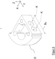
- Fig. 3 shows the receiving element A 2 in a different perspective view, with repeating reference numbers partially omitted.
- This shows Fig. 3 two noses N, which can also be seen in the other figures, which protrude a little from the base body R of the receiving element with a small width and a short length.
- the lugs serve to form a lateral overlap or undercut with respect to the transverse direction Y, in which each lug engages in a suitable recess J on a coupled neighboring element.
- Fig. 1 shows an example of a light barrier that emits a light beam G above the surface W of the measuring system transversely to the conveying direction in order to be able to detect the beginning or end of a passing train with an opposite receiver.
- the lugs N block this light beam (depending on the direction of the light beam, the overlap or undercut can also be designed with respect to a different spatial direction. If the light barrier detects in the height direction Z, appropriately arranged lugs could provide the required Alternatively, form a cover in the height direction Z).
- Fig. 4 shows an embodiment of a distance element D. This is not used to hold test weights, but in particular to determine a predeterminable distance between two other elements of a train. It extends over a width B D , a length L D and a height H D . According to the example Fig. 1 The width and height of all elements are chosen to be the same size.
- the spacer element In order to make the spacer element as light as possible, it can - as in Fig. 4 is shown - for example, be manufactured as a honeycomb structure.
- the rectangular or square structure in the present case is formed by four circumferential wall sections representing the outer sides of the spacer element D. Two further wall sections extend diagonally between opposite corners and give the spacer D the necessary rigidity.
- the spacer elements of the test body system are also equipped with coupling means (K) in order to be coupled to other elements (receiving element or further spacer element).
- the coupling means K interacting with a spacer element D are preferably designed or positioned in the same way as those of a receiving element in order to be able to selectively couple a receiving element or a further spacer element.
- the noses N and recesses H already presented for the receiving elements are also provided on the spacer elements in order to achieve the desired undercut.
- Fig. 5 shows another receiving element A, which has a quarter circle cross section in plan view.
- the receiving element A can be coupled to another element using the indicated coupling means become. No further coupling means are provided along the quarter circle circumference, since this receiving element A is intended to form the beginning or end of a train.
- the width B A of the receiving element A is only half as large as that of, for example Fig. 1 elements shown.
- Another quarter-circle-shaped receiving element A can be positioned next to the receiving element A in the transverse direction Y Fig. 5 Arrange that both receiving elements together form a semicircular front with a total width that is, for example, that in Fig. 1 corresponds to the width of the train shown.
- receiving elements or spacer elements can also connect to the first quarter-circle-shaped receiving element A in the transverse direction, before the arrangement ends again in the transverse direction with a quarter-circle-shaped receiving element A.
- the distance elements and receiving elements shown in the figures do not show any coupling means that enable coupling in the transverse direction Y, such a coupling or the provision of suitable coupling means is easily alternatively or additionally possible. Accordingly, it is possible to form a train T which has more than just one element in the transverse direction and/or in the longitudinal direction.
- the size of the individual elements can be chosen differently and according to a grid in which the width or length of one element corresponds to a multiple of the width or length of another element.
- Fig. 6 shows an example of some unlabeled trains T, which extend in the longitudinal direction X and each begin and end with a semicircular receiving element. In between, further receiving elements or spacer elements can be arranged in a freely selectable order and length, with elements lying immediately behind one another in the longitudinal direction Fig. 6 Coupling means, not shown, are coupled to one another.
- Fig. 7a shows the coupling of two elements in an enlarged, simplified representation.
- the area marked by the dash-dotted circle A of two receiving elements A 1 and A 2 coupled to one another in the longitudinal direction X is shown enlarged in the lower part in a top view against the height direction Z.
- Coupling element shown in simplified form is inserted as part of the coupling means K between the two receiving elements.
- the coupling element is essentially designed to be rotationally symmetrical about a longitudinal axis.
- Two separate connecting means E 1 , E 2 in the form of threaded rods extend from a centrally arranged elastic core M in opposite directions along the axis of rotation.
- the threaded rods are intended to be passed through a hole in one of the two elements A 1 , A 2 to be coupled to one another and screwed to the rear with nuts.
- the coupling of two elements is preferably carried out via double coupling means, which are preferably positioned symmetrically to a central XZ plane on the elements.
- the two threaded rods E 1 , E 2 adjoining the elastic core M on both sides - and thus also the elements A 1 , A 2 screwed to them - are movable relative to one another due to the elastic core M, so that, depending on the elasticity, translational and / or rotational relative movements between the coupled elements are possible.
- the coupling means are designed such that two elements A 1 , A 2 coupled to one another have a small distance or gap G between them.
- Fig. 8 shows an alternative embodiment of the coupling means K in a simplified representation.
- the coupling means include a dumbbell-like body, which is similar to the example according to Fig. 7b has a central elastic section M with two extending in the opposite direction, web- or rod-shaped connecting means E 1 , E 2 .
- the connecting means are not designed as threaded rods. Instead, they each have a flange-like extension P at their ends.
- a simplified end wall of an element A there is an elongated groove running in the height direction Z, the diameter of which corresponds approximately to the outer diameter of the connecting means E ( Fig. 8a ).
- the dumbbell-like coupling means can be inserted into the groove S using one of the two connecting means E in such a way that the associated flange P engages behind the end wall of the element A, preferably in a clamping manner, while the elastic section M comes to rest on the outside of the element ( Fig. 8b ) and preferably clamps the wall section in between.
- An element arranged opposite element A (and in Fig. 8 (not shown) further element can be coupled accordingly with a similarly designed groove S in its end face via the other connecting means E with the associated flange P, so that the elastic region M is arranged, preferably without play, between the two elements coupled to one another in this way.
- This coupling can be produced or released particularly easily and without tools by simply inserting the dumbbell-like coupling means into the respective groove S in or against the height direction Z between two elements A to be coupled to one another.
Landscapes
- Physics & Mathematics (AREA)
- General Physics & Mathematics (AREA)
- Investigating Strength Of Materials By Application Of Mechanical Stress (AREA)
- Testing Of Devices, Machine Parts, Or Other Structures Thereof (AREA)
- A Measuring Device Byusing Mechanical Method (AREA)
Applications Claiming Priority (2)
| Application Number | Priority Date | Filing Date | Title |
|---|---|---|---|
| DE102019135601.6A DE102019135601B4 (de) | 2019-12-20 | 2019-12-20 | Prüfkörpersystem |
| PCT/DE2020/101079 WO2021121486A1 (de) | 2019-12-20 | 2020-12-18 | Prüfkörpersystem |
Publications (3)
| Publication Number | Publication Date |
|---|---|
| EP4078112A1 EP4078112A1 (de) | 2022-10-26 |
| EP4078112C0 EP4078112C0 (de) | 2024-03-20 |
| EP4078112B1 true EP4078112B1 (de) | 2024-03-20 |
Family
ID=74186404
Family Applications (1)
| Application Number | Title | Priority Date | Filing Date |
|---|---|---|---|
| EP20842185.9A Active EP4078112B1 (de) | 2019-12-20 | 2020-12-18 | Prüfkörpersystem |
Country Status (7)
| Country | Link |
|---|---|
| US (1) | US12366477B2 (pl) |
| EP (1) | EP4078112B1 (pl) |
| JP (1) | JP7370469B2 (pl) |
| CN (1) | CN115003994B (pl) |
| DE (1) | DE102019135601B4 (pl) |
| PL (1) | PL4078112T3 (pl) |
| WO (1) | WO2021121486A1 (pl) |
Family Cites Families (27)
| Publication number | Priority date | Publication date | Assignee | Title |
|---|---|---|---|---|
| GB780321A (en) | 1954-03-16 | 1957-07-31 | Charles Lincoln Bettinson | Improvements relating to sets of weights for use with weighing apparatus |
| US3396573A (en) | 1965-09-22 | 1968-08-13 | Galion Jeffrey Mfg Co | Calibration of belt conveyor scales |
| FR2707184B1 (fr) * | 1993-07-08 | 1995-08-11 | Rhone Poulenc Nutrition Animal | Procédé de préparation de sphérules contenant un principe actif alimentaire ou pharmaceutique. |
| JPH07139992A (ja) | 1993-11-18 | 1995-06-02 | Oumi Doriyoukou Kk | 検量装置 |
| DE19631709B4 (de) | 1996-08-06 | 2004-03-18 | Löschel, Kurt | Eichnormalpalette |
| JPH1078347A (ja) | 1996-09-04 | 1998-03-24 | Japan Steel Works Ltd:The | ベルト式重量フィーダのスパン校正方法及びスパン校正用チェーン |
| DE29621304U1 (de) * | 1996-12-07 | 1997-02-27 | Wiese, Claus, 58285 Gevelsberg | Eichvorrichtung für Gleiswaagen |
| DK174518B1 (da) * | 1999-01-15 | 2003-05-05 | Lego As | Legetøjsbyggesæt |
| JP3858114B2 (ja) | 2000-04-10 | 2006-12-13 | 独立行政法人産業技術総合研究所 | 重錘型圧力標準器 |
| DE10142232B4 (de) * | 2001-08-29 | 2021-04-29 | Roche Diabetes Care Gmbh | Verfahren zur Herstellung eines analytischen Hilfsmittels mit Lanzette und Testelement |
| US6648715B2 (en) * | 2001-10-25 | 2003-11-18 | Benjamin I. Wiens | Snap-fit construction system |
| CN2574024Y (zh) | 2002-09-28 | 2003-09-17 | 南京金杰出科技实业有限公司 | 电子皮带秤标定用小车链码 |
| DE102005018708B4 (de) * | 2005-04-21 | 2007-01-11 | Wipotec Wiege- Und Positioniersysteme Gmbh | Wägevorrichtung, insbesondere Mehrspur-Wägevorrichtung |
| DE202005010429U1 (de) | 2005-06-30 | 2005-09-15 | Fischdick Rolf | Eichgerätschaft für Gleiswaagen |
| EP1876431B1 (de) * | 2006-07-07 | 2013-08-21 | Mettler-Toledo AG | Messgerät zur gravimetrischen Feuchtigkeitsbestimmung |
| DE202008012406U1 (de) * | 2008-09-17 | 2008-11-13 | Wipotec Wiege- Und Positioniersysteme Gmbh | Prüfkörper |
| CN202393486U (zh) * | 2011-12-06 | 2012-08-22 | 山东三恩电子有限公司 | 电子皮带秤的校正装置及用于该装置的校正砝码 |
| DE102012110586A1 (de) * | 2012-10-15 | 2014-04-17 | Continental Safety Engineering International Gmbh | Verbindungsvorrichtung und Testanordnung |
| CN202974415U (zh) | 2012-12-01 | 2013-06-05 | 新余钢铁集团有限公司 | 一种用于自动校秤的砝码 |
| JP6033959B2 (ja) * | 2013-01-09 | 2016-11-30 | テカン・トレーディング・アクチェンゲゼルシャフトTECAN Trading AG | マイクロ流体システム用使い捨てカートリッジ |
| DE102014013622B4 (de) * | 2014-09-19 | 2016-12-15 | Rüdiger Wöhrl GmbH | Fahrzeug zum Eichen von Fahrzeugwaagen |
| GB201515483D0 (en) * | 2015-09-01 | 2015-10-14 | Rolls Royce Plc | Multi-element sensor array calibration method |
| CN205843804U (zh) | 2016-07-13 | 2016-12-28 | 徐州赛默威尔测控技术有限公司 | 动态链码标定装置 |
| DE102016125646A1 (de) * | 2016-12-23 | 2018-06-28 | Wipotec Wiege- Und Positioniersysteme Gmbh | Mess- und/oder Sensorvorrichtung mit einer Kamera |
| EP3376184A3 (de) * | 2017-02-28 | 2018-12-05 | Kistler Holding AG | Vorrichtung und verfahren zum kalibrieren eines weigh-in-motion sensors |
| JP6385542B1 (ja) | 2017-09-27 | 2018-09-05 | 鎌長製衡株式会社 | テストチェーン |
| DE102020211564A1 (de) * | 2020-09-15 | 2022-03-17 | Zf Automotive Germany Gmbh | Rasteinrichtung, Lenkvorrichtung mit einer solchen Rasteinrichtung und Verfahren zum Herstellen einer formschlüssigen Rastverbindung mit einer solchen Rasteinrichtung |
-
2019
- 2019-12-20 DE DE102019135601.6A patent/DE102019135601B4/de active Active
-
2020
- 2020-12-18 PL PL20842185.9T patent/PL4078112T3/pl unknown
- 2020-12-18 EP EP20842185.9A patent/EP4078112B1/de active Active
- 2020-12-18 WO PCT/DE2020/101079 patent/WO2021121486A1/de not_active Ceased
- 2020-12-18 JP JP2022537237A patent/JP7370469B2/ja active Active
- 2020-12-18 CN CN202080093459.4A patent/CN115003994B/zh active Active
- 2020-12-18 US US17/786,466 patent/US12366477B2/en active Active
Also Published As
| Publication number | Publication date |
|---|---|
| JP7370469B2 (ja) | 2023-10-27 |
| DE102019135601A1 (de) | 2021-06-24 |
| PL4078112T3 (pl) | 2024-09-09 |
| WO2021121486A1 (de) | 2021-06-24 |
| CN115003994A (zh) | 2022-09-02 |
| US12366477B2 (en) | 2025-07-22 |
| EP4078112C0 (de) | 2024-03-20 |
| US20230221171A1 (en) | 2023-07-13 |
| DE102019135601B4 (de) | 2023-11-16 |
| EP4078112A1 (de) | 2022-10-26 |
| JP2023506945A (ja) | 2023-02-20 |
| CN115003994B (zh) | 2024-05-24 |
Similar Documents
| Publication | Publication Date | Title |
|---|---|---|
| EP3845874B1 (de) | Regal | |
| CH635455A5 (de) | Bausatz, insbesondere fuer ausstellungsanordnungen. | |
| EP2028142B1 (de) | Magazin für Speicherstäbe für die Aufnahme wurstförmiger Produkte und Verfahren zum Zuführen der Speicherstäbe | |
| EP0895069B1 (de) | Tablettentestgerät | |
| EP0819922A2 (de) | Schocksicherung für eine Kraftmessvorrichtung | |
| DE3923288C2 (pl) | ||
| EP0259406B1 (de) | Rollstein und aus rollsteinen zusammengesetzte rollbahn | |
| EP4078112B1 (de) | Prüfkörpersystem | |
| EP2497726B1 (de) | Matte für den Transport von mindestens einem Gegenstand, Übergabevorrichtung und Verfahren zur Übergabe | |
| DE7719231U1 (de) | Metallgitterrost | |
| EP3982114A1 (de) | Halterung für ein zu untersuchendes objekt | |
| EP1785704A1 (de) | Wägemodul | |
| EP1570962A1 (de) | Vorrichtung und Verfahren zum Schneiden von Lebensmittelprodukten | |
| WO2007107405A1 (de) | Transportsystem | |
| EP3258224A1 (de) | Abstandhalter zum halten eines abstandes zwischen einem stabförmigen innenleiter und einem aussenleiter einer füllstand-messsonde | |
| DE102016212728A1 (de) | Prüfaufbau für Biegeversuche an CFK Bauteilen | |
| DE69702124T2 (de) | Vorrichtung zum lösbaren befestigen von zylindrischen gegenständen auf einem fahrzeug | |
| DE10204104C1 (de) | Anordnung zur Überwachung des Füllungsgrades von einzelnen Behältern in einem Lagersystem | |
| DE10035450B4 (de) | Verfahren und Vorrichtung zum Einsetzen länglicher Werkstücke in einen Transportrost | |
| DE202007018846U1 (de) | Transportvorrichtung zum Transport mehrerer quaderförmiger Geräte | |
| EP0143990A1 (de) | Vorrichtung zum Prüfen und Sortieren von elektronischen Bauteilen, insbesondere von integrierten Chips | |
| DE202024101650U1 (de) | Messvorrichtung für Pakete | |
| DE3621855C2 (pl) | ||
| DE102022205909A1 (de) | Modulares Transport- und Lagerhilfsmittel | |
| DE102023102870A1 (de) | Erfassungsvorrichtung |
Legal Events
| Date | Code | Title | Description |
|---|---|---|---|
| STAA | Information on the status of an ep patent application or granted ep patent |
Free format text: STATUS: UNKNOWN |
|
| STAA | Information on the status of an ep patent application or granted ep patent |
Free format text: STATUS: THE INTERNATIONAL PUBLICATION HAS BEEN MADE |
|
| PUAI | Public reference made under article 153(3) epc to a published international application that has entered the european phase |
Free format text: ORIGINAL CODE: 0009012 |
|
| STAA | Information on the status of an ep patent application or granted ep patent |
Free format text: STATUS: REQUEST FOR EXAMINATION WAS MADE |
|
| 17P | Request for examination filed |
Effective date: 20220705 |
|
| AK | Designated contracting states |
Kind code of ref document: A1 Designated state(s): AL AT BE BG CH CY CZ DE DK EE ES FI FR GB GR HR HU IE IS IT LI LT LU LV MC MK MT NL NO PL PT RO RS SE SI SK SM TR |
|
| DAV | Request for validation of the european patent (deleted) | ||
| DAX | Request for extension of the european patent (deleted) | ||
| GRAP | Despatch of communication of intention to grant a patent |
Free format text: ORIGINAL CODE: EPIDOSNIGR1 |
|
| STAA | Information on the status of an ep patent application or granted ep patent |
Free format text: STATUS: GRANT OF PATENT IS INTENDED |
|
| INTG | Intention to grant announced |
Effective date: 20231107 |
|
| GRAS | Grant fee paid |
Free format text: ORIGINAL CODE: EPIDOSNIGR3 |
|
| GRAA | (expected) grant |
Free format text: ORIGINAL CODE: 0009210 |
|
| STAA | Information on the status of an ep patent application or granted ep patent |
Free format text: STATUS: THE PATENT HAS BEEN GRANTED |
|
| AK | Designated contracting states |
Kind code of ref document: B1 Designated state(s): AL AT BE BG CH CY CZ DE DK EE ES FI FR GB GR HR HU IE IS IT LI LT LU LV MC MK MT NL NO PL PT RO RS SE SI SK SM TR |
|
| REG | Reference to a national code |
Ref country code: GB Ref legal event code: FG4D Free format text: NOT ENGLISH |
|
| REG | Reference to a national code |
Ref country code: CH Ref legal event code: EP |
|
| REG | Reference to a national code |
Ref country code: IE Ref legal event code: FG4D Free format text: LANGUAGE OF EP DOCUMENT: GERMAN |
|
| REG | Reference to a national code |
Ref country code: DE Ref legal event code: R096 Ref document number: 502020007439 Country of ref document: DE |
|
| U01 | Request for unitary effect filed |
Effective date: 20240419 |
|
| U07 | Unitary effect registered |
Designated state(s): AT BE BG DE DK EE FI FR IT LT LU LV MT NL PT SE SI Effective date: 20240424 |
|
| PG25 | Lapsed in a contracting state [announced via postgrant information from national office to epo] |
Ref country code: GR Free format text: LAPSE BECAUSE OF FAILURE TO SUBMIT A TRANSLATION OF THE DESCRIPTION OR TO PAY THE FEE WITHIN THE PRESCRIBED TIME-LIMIT Effective date: 20240621 |
|
| PG25 | Lapsed in a contracting state [announced via postgrant information from national office to epo] |
Ref country code: RS Free format text: LAPSE BECAUSE OF FAILURE TO SUBMIT A TRANSLATION OF THE DESCRIPTION OR TO PAY THE FEE WITHIN THE PRESCRIBED TIME-LIMIT Effective date: 20240620 Ref country code: HR Free format text: LAPSE BECAUSE OF FAILURE TO SUBMIT A TRANSLATION OF THE DESCRIPTION OR TO PAY THE FEE WITHIN THE PRESCRIBED TIME-LIMIT Effective date: 20240320 |
|
| PG25 | Lapsed in a contracting state [announced via postgrant information from national office to epo] |
Ref country code: RS Free format text: LAPSE BECAUSE OF FAILURE TO SUBMIT A TRANSLATION OF THE DESCRIPTION OR TO PAY THE FEE WITHIN THE PRESCRIBED TIME-LIMIT Effective date: 20240620 Ref country code: NO Free format text: LAPSE BECAUSE OF FAILURE TO SUBMIT A TRANSLATION OF THE DESCRIPTION OR TO PAY THE FEE WITHIN THE PRESCRIBED TIME-LIMIT Effective date: 20240620 Ref country code: HR Free format text: LAPSE BECAUSE OF FAILURE TO SUBMIT A TRANSLATION OF THE DESCRIPTION OR TO PAY THE FEE WITHIN THE PRESCRIBED TIME-LIMIT Effective date: 20240320 Ref country code: GR Free format text: LAPSE BECAUSE OF FAILURE TO SUBMIT A TRANSLATION OF THE DESCRIPTION OR TO PAY THE FEE WITHIN THE PRESCRIBED TIME-LIMIT Effective date: 20240621 |
|
| PG25 | Lapsed in a contracting state [announced via postgrant information from national office to epo] |
Ref country code: IS Free format text: LAPSE BECAUSE OF FAILURE TO SUBMIT A TRANSLATION OF THE DESCRIPTION OR TO PAY THE FEE WITHIN THE PRESCRIBED TIME-LIMIT Effective date: 20240720 |
|
| PG25 | Lapsed in a contracting state [announced via postgrant information from national office to epo] |
Ref country code: SM Free format text: LAPSE BECAUSE OF FAILURE TO SUBMIT A TRANSLATION OF THE DESCRIPTION OR TO PAY THE FEE WITHIN THE PRESCRIBED TIME-LIMIT Effective date: 20240320 |
|
| PG25 | Lapsed in a contracting state [announced via postgrant information from national office to epo] |
Ref country code: ES Free format text: LAPSE BECAUSE OF FAILURE TO SUBMIT A TRANSLATION OF THE DESCRIPTION OR TO PAY THE FEE WITHIN THE PRESCRIBED TIME-LIMIT Effective date: 20240320 |
|
| PG25 | Lapsed in a contracting state [announced via postgrant information from national office to epo] |
Ref country code: CZ Free format text: LAPSE BECAUSE OF FAILURE TO SUBMIT A TRANSLATION OF THE DESCRIPTION OR TO PAY THE FEE WITHIN THE PRESCRIBED TIME-LIMIT Effective date: 20240320 |
|
| PG25 | Lapsed in a contracting state [announced via postgrant information from national office to epo] |
Ref country code: SK Free format text: LAPSE BECAUSE OF FAILURE TO SUBMIT A TRANSLATION OF THE DESCRIPTION OR TO PAY THE FEE WITHIN THE PRESCRIBED TIME-LIMIT Effective date: 20240320 |
|
| PG25 | Lapsed in a contracting state [announced via postgrant information from national office to epo] |
Ref country code: SM Free format text: LAPSE BECAUSE OF FAILURE TO SUBMIT A TRANSLATION OF THE DESCRIPTION OR TO PAY THE FEE WITHIN THE PRESCRIBED TIME-LIMIT Effective date: 20240320 Ref country code: SK Free format text: LAPSE BECAUSE OF FAILURE TO SUBMIT A TRANSLATION OF THE DESCRIPTION OR TO PAY THE FEE WITHIN THE PRESCRIBED TIME-LIMIT Effective date: 20240320 Ref country code: RO Free format text: LAPSE BECAUSE OF FAILURE TO SUBMIT A TRANSLATION OF THE DESCRIPTION OR TO PAY THE FEE WITHIN THE PRESCRIBED TIME-LIMIT Effective date: 20240320 Ref country code: IS Free format text: LAPSE BECAUSE OF FAILURE TO SUBMIT A TRANSLATION OF THE DESCRIPTION OR TO PAY THE FEE WITHIN THE PRESCRIBED TIME-LIMIT Effective date: 20240720 Ref country code: ES Free format text: LAPSE BECAUSE OF FAILURE TO SUBMIT A TRANSLATION OF THE DESCRIPTION OR TO PAY THE FEE WITHIN THE PRESCRIBED TIME-LIMIT Effective date: 20240320 Ref country code: CZ Free format text: LAPSE BECAUSE OF FAILURE TO SUBMIT A TRANSLATION OF THE DESCRIPTION OR TO PAY THE FEE WITHIN THE PRESCRIBED TIME-LIMIT Effective date: 20240320 |
|
| U20 | Renewal fee for the european patent with unitary effect paid |
Year of fee payment: 5 Effective date: 20241104 |
|
| REG | Reference to a national code |
Ref country code: DE Ref legal event code: R097 Ref document number: 502020007439 Country of ref document: DE |
|
| PLBE | No opposition filed within time limit |
Free format text: ORIGINAL CODE: 0009261 |
|
| STAA | Information on the status of an ep patent application or granted ep patent |
Free format text: STATUS: NO OPPOSITION FILED WITHIN TIME LIMIT |
|
| 26N | No opposition filed |
Effective date: 20241223 |
|
| PGFP | Annual fee paid to national office [announced via postgrant information from national office to epo] |
Ref country code: CH Payment date: 20250101 Year of fee payment: 5 |
|
| PG25 | Lapsed in a contracting state [announced via postgrant information from national office to epo] |
Ref country code: MC Free format text: LAPSE BECAUSE OF FAILURE TO SUBMIT A TRANSLATION OF THE DESCRIPTION OR TO PAY THE FEE WITHIN THE PRESCRIBED TIME-LIMIT Effective date: 20240320 |
|
| GBPC | Gb: european patent ceased through non-payment of renewal fee |
Effective date: 20241218 |
|
| PG25 | Lapsed in a contracting state [announced via postgrant information from national office to epo] |
Ref country code: GB Free format text: LAPSE BECAUSE OF NON-PAYMENT OF DUE FEES Effective date: 20241218 |
|
| PG25 | Lapsed in a contracting state [announced via postgrant information from national office to epo] |
Ref country code: IE Free format text: LAPSE BECAUSE OF NON-PAYMENT OF DUE FEES Effective date: 20241218 |
|
| REG | Reference to a national code |
Ref country code: CH Ref legal event code: U11 Free format text: ST27 STATUS EVENT CODE: U-0-0-U10-U11 (AS PROVIDED BY THE NATIONAL OFFICE) Effective date: 20260101 |
|
| U20 | Renewal fee for the european patent with unitary effect paid |
Year of fee payment: 6 Effective date: 20251130 |
|
| PGFP | Annual fee paid to national office [announced via postgrant information from national office to epo] |
Ref country code: PL Payment date: 20251208 Year of fee payment: 6 |