EP4076901B1 - Vorrichtung zum erwärmen von kunststoffrohlingen, die eine vorrichtung zum schutz von vorformlingshälsen umfasst - Google Patents
Vorrichtung zum erwärmen von kunststoffrohlingen, die eine vorrichtung zum schutz von vorformlingshälsen umfasst Download PDFInfo
- Publication number
- EP4076901B1 EP4076901B1 EP20830212.5A EP20830212A EP4076901B1 EP 4076901 B1 EP4076901 B1 EP 4076901B1 EP 20830212 A EP20830212 A EP 20830212A EP 4076901 B1 EP4076901 B1 EP 4076901B1
- Authority
- EP
- European Patent Office
- Prior art keywords
- heating unit
- actuating member
- preforms
- shell
- supports
- Prior art date
- Legal status (The legal status is an assumption and is not a legal conclusion. Google has not performed a legal analysis and makes no representation as to the accuracy of the status listed.)
- Active
Links
Images


Classifications
-
- B—PERFORMING OPERATIONS; TRANSPORTING
- B29—WORKING OF PLASTICS; WORKING OF SUBSTANCES IN A PLASTIC STATE IN GENERAL
- B29C—SHAPING OR JOINING OF PLASTICS; SHAPING OF MATERIAL IN A PLASTIC STATE, NOT OTHERWISE PROVIDED FOR; AFTER-TREATMENT OF THE SHAPED PRODUCTS, e.g. REPAIRING
- B29C49/00—Blow-moulding, i.e. blowing a preform or parison to a desired shape within a mould; Apparatus therefor
- B29C49/42—Component parts, details or accessories; Auxiliary operations
- B29C49/64—Heating or cooling preforms, parisons or blown articles
- B29C49/6409—Thermal conditioning of preforms
- B29C49/6436—Thermal conditioning of preforms characterised by temperature differential
- B29C49/6445—Thermal conditioning of preforms characterised by temperature differential through the preform length
-
- B—PERFORMING OPERATIONS; TRANSPORTING
- B29—WORKING OF PLASTICS; WORKING OF SUBSTANCES IN A PLASTIC STATE IN GENERAL
- B29C—SHAPING OR JOINING OF PLASTICS; SHAPING OF MATERIAL IN A PLASTIC STATE, NOT OTHERWISE PROVIDED FOR; AFTER-TREATMENT OF THE SHAPED PRODUCTS, e.g. REPAIRING
- B29C49/00—Blow-moulding, i.e. blowing a preform or parison to a desired shape within a mould; Apparatus therefor
- B29C49/42—Component parts, details or accessories; Auxiliary operations
- B29C49/64—Heating or cooling preforms, parisons or blown articles
- B29C49/68—Ovens specially adapted for heating preforms or parisons
- B29C49/682—Ovens specially adapted for heating preforms or parisons characterised by the path, e.g. sinusoidal path
-
- B—PERFORMING OPERATIONS; TRANSPORTING
- B29—WORKING OF PLASTICS; WORKING OF SUBSTANCES IN A PLASTIC STATE IN GENERAL
- B29C—SHAPING OR JOINING OF PLASTICS; SHAPING OF MATERIAL IN A PLASTIC STATE, NOT OTHERWISE PROVIDED FOR; AFTER-TREATMENT OF THE SHAPED PRODUCTS, e.g. REPAIRING
- B29C49/00—Blow-moulding, i.e. blowing a preform or parison to a desired shape within a mould; Apparatus therefor
- B29C49/42—Component parts, details or accessories; Auxiliary operations
- B29C49/64—Heating or cooling preforms, parisons or blown articles
- B29C49/68—Ovens specially adapted for heating preforms or parisons
- B29C49/684—Ovens specially adapted for heating preforms or parisons using masking
-
- B—PERFORMING OPERATIONS; TRANSPORTING
- B29—WORKING OF PLASTICS; WORKING OF SUBSTANCES IN A PLASTIC STATE IN GENERAL
- B29B—PREPARATION OR PRETREATMENT OF THE MATERIAL TO BE SHAPED; MAKING GRANULES OR PREFORMS; RECOVERY OF PLASTICS OR OTHER CONSTITUENTS OF WASTE MATERIAL CONTAINING PLASTICS
- B29B11/00—Making preforms
- B29B11/14—Making preforms characterised by structure or composition
-
- B—PERFORMING OPERATIONS; TRANSPORTING
- B29—WORKING OF PLASTICS; WORKING OF SUBSTANCES IN A PLASTIC STATE IN GENERAL
- B29C—SHAPING OR JOINING OF PLASTICS; SHAPING OF MATERIAL IN A PLASTIC STATE, NOT OTHERWISE PROVIDED FOR; AFTER-TREATMENT OF THE SHAPED PRODUCTS, e.g. REPAIRING
- B29C49/00—Blow-moulding, i.e. blowing a preform or parison to a desired shape within a mould; Apparatus therefor
- B29C49/02—Combined blow-moulding and manufacture of the preform or the parison
- B29C2049/024—Combined blow-moulding and manufacture of the preform or the parison not using inherent heat of the preform, i.e. 2 step blow moulding
-
- B—PERFORMING OPERATIONS; TRANSPORTING
- B29—WORKING OF PLASTICS; WORKING OF SUBSTANCES IN A PLASTIC STATE IN GENERAL
- B29C—SHAPING OR JOINING OF PLASTICS; SHAPING OF MATERIAL IN A PLASTIC STATE, NOT OTHERWISE PROVIDED FOR; AFTER-TREATMENT OF THE SHAPED PRODUCTS, e.g. REPAIRING
- B29C2949/00—Indexing scheme relating to blow-moulding
- B29C2949/07—Preforms or parisons characterised by their configuration
- B29C2949/0715—Preforms or parisons characterised by their configuration the preform having one end closed
-
- B—PERFORMING OPERATIONS; TRANSPORTING
- B29—WORKING OF PLASTICS; WORKING OF SUBSTANCES IN A PLASTIC STATE IN GENERAL
- B29C—SHAPING OR JOINING OF PLASTICS; SHAPING OF MATERIAL IN A PLASTIC STATE, NOT OTHERWISE PROVIDED FOR; AFTER-TREATMENT OF THE SHAPED PRODUCTS, e.g. REPAIRING
- B29C49/00—Blow-moulding, i.e. blowing a preform or parison to a desired shape within a mould; Apparatus therefor
- B29C49/071—Preforms or parisons characterised by their configuration, e.g. geometry, dimensions or physical properties
-
- B—PERFORMING OPERATIONS; TRANSPORTING
- B29—WORKING OF PLASTICS; WORKING OF SUBSTANCES IN A PLASTIC STATE IN GENERAL
- B29C—SHAPING OR JOINING OF PLASTICS; SHAPING OF MATERIAL IN A PLASTIC STATE, NOT OTHERWISE PROVIDED FOR; AFTER-TREATMENT OF THE SHAPED PRODUCTS, e.g. REPAIRING
- B29C49/00—Blow-moulding, i.e. blowing a preform or parison to a desired shape within a mould; Apparatus therefor
- B29C49/42—Component parts, details or accessories; Auxiliary operations
- B29C49/4205—Handling means, e.g. transfer, loading or discharging means
- B29C49/42073—Grippers
- B29C49/42087—Grippers holding outside the neck
-
- B—PERFORMING OPERATIONS; TRANSPORTING
- B29—WORKING OF PLASTICS; WORKING OF SUBSTANCES IN A PLASTIC STATE IN GENERAL
- B29C—SHAPING OR JOINING OF PLASTICS; SHAPING OF MATERIAL IN A PLASTIC STATE, NOT OTHERWISE PROVIDED FOR; AFTER-TREATMENT OF THE SHAPED PRODUCTS, e.g. REPAIRING
- B29C49/00—Blow-moulding, i.e. blowing a preform or parison to a desired shape within a mould; Apparatus therefor
- B29C49/42—Component parts, details or accessories; Auxiliary operations
- B29C49/64—Heating or cooling preforms, parisons or blown articles
- B29C49/6409—Thermal conditioning of preforms
- B29C49/6436—Thermal conditioning of preforms characterised by temperature differential
- B29C49/6462—Thermal conditioning of preforms characterised by temperature differential by masking
Definitions
- the field of the invention is that of the design and manufacture of plastic containers.
- the invention relates to a preform neck protection device for a preform heating unit.
- plastic containers can be obtained by heating a plastic preform above a glass transition temperature.
- the heated preforms are inserted into a mold in the shape of the final container or an intermediate container, to be blown into it by injection of a fluid. More precisely, air is injected into the preform to deform it and stretch the plastic material until it comes into contact with the walls of the mold.
- heating units also called “ovens”.
- the preforms circulate in a parade in the heating units while being held by a turntable, that is to say a finger engaging with the neck, and more precisely with the inside of the neck.
- These heating units use arrays of light sources, typically laser diodes or halogen lamps, which emit a radiation aimed at heating the plastic material, and therefore softening it to promote its stretching and deformation in the mold.
- light sources typically laser diodes or halogen lamps
- the neck of the preforms which is generally shaped like the neck of the final container, is not intended to be heated.
- heating the neck leads to a risk of deformation which can prevent the correct use of the final container, for example preventing the installation of a stopper to seal the container once filled.
- a widely used technique is to position the preforms neck down and have the neck of the preforms protrude out of the heating unit.
- Reflective screens can be used to reflect light radiation into the interior of the heating unit, and thus confine it within the heating unit.
- the preforms are introduced into the molds by being positioned with the neck at the top.
- the turning step can cause a risk of damage to the preforms.
- Another known technique is to position the preforms in the heating unit with the neck at the top.
- reflectors also called scales
- the preforms are inserted between the preforms and positioned under the collar, i.e. on the side of the body of the preform.
- gripping the preforms by their body can lead to localized cooling in the plastic material, for example due to a thermal gradient between the temperature of the gripping organs and the temperature of the preform.
- the carbon dioxide contained in the drink causes the container to build up internal pressure.
- the incipient ruptures, which create areas of low mechanical resistance, can then turn into cracks in the container and cause it to explode.
- heating unit for preforms conforming to the preamble of claim 1 are essentially disclosed in the publications FR2950283A1 , AT520U1 and US2019/047206A1 .
- the invention aims in particular to overcome the drawbacks of the prior art.
- the invention aims to propose a solution for protecting the necks of the preforms during heating, as well as the integrity of the bodies when removing the preforms from the heating unit.
- the invention also aims to provide such a solution which ensures easy removal of the preforms from the heating unit.
- the invention also aims to provide such a solution which makes it possible to maintain the high rates of the prior art while limiting the risk of damage to the preforms during their removal.
- the invention further aims to provide such a solution which makes it possible to reduce the size of a heating unit compared to a heating unit according to the prior art.
- Such a heating unit makes it possible to effectively protect the neck of the preforms during heating of the body while facilitating the entry and exit of the preforms into or out of the heating unit.
- the opening position of the scales makes it easier to put in place transverse means for removing or inserting the preforms to facilitate their removal or insertion into the heating unit.
- this allows a reduction in the size of the heating unit compared to the prior art since the gripping members are not forced to have to move with the preforms to reach the transverse removal or insertion means located for example below or above the supports.
- the heating unit comprises a chain equipped with a plurality of links, the supports each being mounted on one of the links and comprises a wheel drive of the chain of supports, the wheel having a main axis and each scale having an internal edge extending relative to the conveying path of the preforms on the side of the main rotation axis and an external edge opposite the internal edge.
- the pivot axis is located near the internal edge of the scale, and the means for driving in rotation of the actuating member comprise a direct mechanical connection between the actuating member and a second support contiguous to the first support.
- direct mechanical connection means a mechanical solidarity connection between a portion of the actuating member and a portion of the second support without passing through one or more mechanical members that would be movable relative to one and the other. In other words, the direct mechanical connection does not pass through the links of the chain. However, the direct mechanical connection may pass through an intermediate spacer, bearing, washer, surface coating, or equivalent.
- Each scale, the mechanical connection of the actuating member with the second support comprises a sliding pivot connection, located near the external edge of the scale.
- the sliding pivot connection is notably composed of a rotational movement and a translational movement of the actuating member relative to the second support, along two different axes of movement.
- This pivot connection makes it possible to generate a curvilinear translational movement in the scale, which promotes its opening and in particular makes it possible to provide a spacing between the external edges of two contiguous scales greater than the spacing of the internal edges of two contiguous scales in the open position of the scales. This then makes it possible to facilitate transverse insertion or removal of the preforms.
- the sliding pivot connection is achieved by an oblong slot made on the actuating member and a cylindrical finger housed in the oblong slot and carried by a second support.
- the heating unit comprises a motor member cooperating with the actuating member to move the scale from its protective position to its open position, or vice versa.
- the actuating member is then connected to a support only by its pivot connections, which makes it possible to ensure, independently of the position of the adjoining supports, the movement of the scales from their open position to their protective position or vice versa.
- each drive member comprises a cam path secured to a frame and a roller following the cam path and connected to the actuating member.
- each roller is rotatably mounted on the actuating member with which it cooperates.
- This rotating assembly makes it possible to promote the movement of the scales in the form of a curvilinear translation, which promotes obtaining an opening position of the scales relative to each other in a precise manner, at the desired time, in order to facilitate the removal or insertion of the preforms transversely.
- each scale is mounted on an actuating member by removable fixing means.
- Such an architecture promotes rapid assembly or rapid disassembly of the scales on the heating unit and more particularly on the actuating member.
- such an assembly may be provided with foolproof means to facilitate and ensure the correct positioning of the scales in the heating unit.
- the actuating member has at least one hole transverse to the fixing hole and opening into the fixing hole, the arm having a notch intended to come opposite the hole when the arm is inserted into the fixing hole, and the removable fixing means also comprise a holding member inserted into the hole, the holding member being intended to cooperate with the notch of the arm to prevent the arm from being removed from the fixing hole.
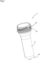
- FIG. 1 illustrates a heating unit 1 according to the invention.
- the gripping members 7, also called turntables, are in the form of mandrels intended to be inserted inside the necks 42 of the preforms 4.
- the gripping members 7 are intended to take and hold each preform 4 to remove it from the feed wheel 3 and make it pass in front of the light source 5.
- each turntable is mounted on a support 6.
- the gripping members 7 and the supports 6 are located near the feed wheel 3.
- the supports 6 are distant from the wheel 3, in particular to present the preforms 4 facing the light source 5.
- the transition from one position to another of the supports 6 is done in particular in a conventional manner by a system of cam tracks and rollers following the cam track.
- the gripping members 7 are movable relative to the support 6 between a high position and a low position.
- the gripping members 7 hold the preforms 4 at a height greater than that at which they are located when they are in the feed wheel 3.
- the gripping members 7 allow the handling of a preform 4 from the feed wheel 3 or the release of the preform 4 at the outlet of the heating unit 1.
- the gripping organs 7 are located in their high position when the supports 6 are located in their holding position. The organs 7 gripping are then in their low position when the supports 6 are located in their admission/release position.
- cam/cam track connections may be provided in particular.
- a pneumatic, electronic or electropneumatic actuator may also be provided to allow mobility of the gripping members 7.
- the scales 8 make it possible to reflect the light radiation emitted by the light source 5 towards the body 41 of the preforms 4, in order to protect the neck 42 of the preform 4.
- each scale 8 advantageously has a coating reflecting light radiation.
- the material constituting the scales may have light reflection properties.
- each scale 8 has an internal edge 81 which can, as in the example illustrated but not necessarily, extend substantially parallel to the preform conveying path.
- the internal edge 81 is located on the side of the preform conveying path which is closest to the main axis of rotation of the wheel 2.
- Each scale 8 also has an external edge 82 opposite the internal edge 81.
- each scale 8 has two circular cutouts 83 opposite each other, and located between the internal edge 81 and the external edge 82.
- the scales 8 are each mounted on at least one support 6.
- the scales 8 In their protective position, the scales 8 then form a barrier to light radiation towards the neck 42.
- each scale 8 is connected by an actuating member 9 to at least one support 6.
- the actuating member 9 is pivotally mounted on said support 6 near the internal edge 81 of the scale 8.
- the actuating member 9 tends to drive the scale 8 from its open position to its protective position during a passage of the support 6 to which it is connected from its admission/release position to its holding position, and vice versa.
- the actuating member 9 is pivotally mounted on a first support 6 and connected to a second support 6 contiguous to the first support 6 near the external edge 82 of the scale 8.
- the actuating member 9 is connected to the second support 6 by a sliding pivot connection.
- the sliding pivot connection is understood here by a connection allowing both a pivoting of the actuating member 9 relative to the second support 6 but also a translation of the actuating member 9 relative to said second support 6.
- the translation axis and the rotation axis of the actuating member 9 are, in the present case, different from each other.
- the movement of the actuating member 9 relative to the second support 6 is a curvilinear translation movement, comparable to a flat support connection, in mechanical terms, the connection between the actuating member 9 and the second support 6 is considered to be a sliding pivot connection in the present case.
- the sliding pivot connection is made by an oblong slot 91 made on the actuating member 9 and a cylindrical finger 92 housed in the oblong slot 91 and carried by the second support 6.
- the oblong slot 91 can be made on the support 6 and the finger 92 carried by the actuating member 9.
- the spacing between the internal edges 81 of two contiguous scales 8 is less than the spacing between the external edges 82 of the same two contiguous scales 8.
- the distance between the inner edges 81 and the outer edges 82 of two contiguous scales 8 is identical.
- the light radiation then reflects on the scales 8 and is redirected towards the body 41 of the preforms 4 to prevent the neck 42 of the preforms from also being heated. This in fact increases the efficiency of the heating of the body 41.
- each scale 8 is mounted on an actuating member 9 by removable fixing means.
- the removable fixing means comprise two fixing holes 10 made in the actuating member 9 and two arms 11 secured to the scale 8 and each intended to be inserted into one of the fixing holes 10.
- the actuating member 9 has at least one hole 12 transverse to the fixing hole 10 and opening into it.
- the removable fixing means and the actuating member 9 have a transverse hole 12 opening only into one of the fixing holes 10.
- Each arm 11 advantageously has a notch 111 intended to come opposite the hole 12 when the arm 11 is inserted into the fixing hole 10.
- the removable fixing means also comprise a holding member 13 intended to be inserted into the transverse hole 12.
- This holding member 13 is intended to cooperate with the notch 111 of the arm 11 to prevent the arm 11 from being removed from the fixing hole 10.
- Such removable fixing means make it possible in particular to carry out, during a maintenance operation or change of preform format, a rapid and easy replacement of the scales 8 when these are intended to be replaced or removed temporarily to allow easy access to the supports or gripping members 7.
- each scale 8 comprises a cartridge 14 carrying the arm(s) 11.
- the fixing of the reflective part of the scale 8 on the cartridge 14 is advantageously carried out by means of rivets 15.
- the heating unit 1 comprises a motor member 93 secured to the frame 2 and intended to cooperate with the actuating member.
- the drive member 93 comprises a cam path 931 secured to the frame 2 and a roller 932 connected to the actuating member 9 and intended to follow the cam path 931. More precisely, each roller 932 is rotatably mounted on the actuating member 9 with which it cooperates.
- the roller 932 when the supports 6 move from their admission/release position to their holding position, the roller 932, following the cam path 931, causes rotation around the pivot connection of the scale 8, to allow it to move from its opening position to its protection position or vice versa.
- the heating unit 1 which has just been described makes it possible to ensure the protection of the necks 42 during the heating of the body 41 of the preforms 4, while ensuring easy loading and unloading of the preforms 4 before and after their heating.
- the spacing of the external edges 82 of the scales 8 in their open position makes it easier for the preforms 4 to exit or enter the heating unit 1, in particular by allowing the preforms to be admitted or removed transversely, i.e. perpendicular to the axis of rotation of the spinners, or almost.
Landscapes
- Physics & Mathematics (AREA)
- Thermal Sciences (AREA)
- Engineering & Computer Science (AREA)
- Manufacturing & Machinery (AREA)
- Mechanical Engineering (AREA)
- Blow-Moulding Or Thermoforming Of Plastics Or The Like (AREA)
Claims (8)
- Einheit (1) zum Erwärmen von Kunststoffrohlingen (4), die einen Körper (41) und einen Hals (42) umfassen, die durch einen Kragen (43) getrennt sind, wobei die Erwärmungseinheit (1) Folgendes umfasst:- eine strahlungsemittierende Lichtquelle (5) zum Erwärmen der Rohlinge (4);- eine Vielzahl von Trägern (6), die jeweils ein Organ (7) zum Greifen der Rohlinge (4) tragen, wobei die Träger (6) in der Erwärmungseinheit beweglich sind, so dass sich jedes Greiforgan entlang eines Förderwegs der Rohlinge bewegt,wobei die Erwärmungseinheit Folgendes aufweist:- einen Aufnahme-/Freigabebereich, in dem die Träger voneinander beabstandet sind;- einen Haltebereich, in dem die Träger aneinander angenähert sind, wobei die Quelle in der Nähe des Haltebereichs angeordnet ist, wobei die Erwärmungseinheit (1) ferner eine Vielzahl von Schuppen (8) umfasst, die fest mit den Trägern (6) verbunden sind, wobei die Schuppen (8) beweglich sind zwischen:- einer Schutzposition, in der sie paarweise aneinanderstoßen, um gemeinsam eine Umrandung zu bilden, die dazu bestimmt ist, sich um den Körper (41) herum und unter dem Kragen (43) eines Rohlings (4) zu erstrecken, um eine Sperre für die Lichtstrahlung in Richtung des Halses (42) zu bilden,- einer Öffnungsposition, in der sie voneinander beabstandet sind, wobei jede Schuppe (8) durch ein Betätigungsorgan (9) mit mindestens einem der Träger (6) verbunden ist, wobei das Betätigungsorgan (9) um eine Schwenkachse, die sich in einem Abstand zum Förderweg der Rohlinge befindet, herum schwenkbar am Träger (6) montiert ist, wobei die Erwärmungseinheit ferner Mittel zum Drehantrieb des Betätigungsorgans relativ zum Träger umfasst, um die Schuppe (8) aus der Öffnungsposition in die Schutzposition zu bewegen, wenn sich der Träger (6), mit dem sie verbunden ist, aus dem Aufnahme-/Freigabebereich zum Haltebereich bewegt;eine Kette, die mit einer Vielzahl von Gliedern ausgestattet ist, wobei die Träger jeweils an einem der Glieder montiert sind, und die ein Antriebsrad für die Kette der Träger umfasst, wobei das Rad eine Hauptachse aufweist und jede Schuppe (8) eine Innenkante (81), die sich relativ zum Förderweg der Rohlinge auf der Seite der Hauptrotationsachse erstreckt, und eine der Innenkante (81) gegenüberliegende Außenkante (82) aufweist, wobei sich für jede Schuppe (8) die Schwenkachse in der Nähe der Innenkante (81) der Schuppe (8) befindet und die Drehantriebsmittel des Betätigungsorgans eine direkte mechanische Verbindung zwischen dem Betätigungsorgan und einem an den ersten Träger (6) angrenzenden zweiten Träger (6) umfassen;dadurch gekennzeichnet, dass für jede Schuppe (8) die mechanische Verbindung des Betätigungsorgans (9) mit dem zweiten Träger (6) eine gleitende Schwenkverbindung umfasst, die sich in der Nähe der Außenkante (82) der Schuppe (8) befindet.
- Erwärmungseinheit (1) nach dem vorangehenden Anspruch, dadurch gekennzeichnet, dass die gleitende Schwenkverbindung durch eine am Betätigungsorgan (9) vorgesehene längliche Öffnung (91) und einen zylindrischen Finger (92), der in der länglichen Öffnung (91) untergebracht ist und vom zweiten Träger (6) getragen wird, hergestellt ist.
- Erwärmungseinheit (1) nach Anspruch 1, dadurch gekennzeichnet, dass die Erwärmungseinheit (1) für jede Schuppe (8) ein Antriebsorgan (93) umfasst, das mit dem Betätigungsorgan (9) zusammenwirkt, um die Schuppe (8) aus ihrer Schutzposition in ihre Öffnungsposition oder umgekehrt zu bewegen.
- Erwärmungseinheit (1) nach dem vorangehenden Anspruch, dadurch gekennzeichnet, dass jedes Antriebsorgan (93) eine Nockenbahn (931), die fest mit einem Gestell verbunden ist, und eine Rolle (932), die der Nockenbahn (931) folgt und mit dem Betätigungsorgan (9) verbunden ist, umfasst.
- Erwärmungseinheit (1) nach dem vorangehenden Anspruch, dadurch gekennzeichnet, dass jede Rolle (932) drehbar am Betätigungsorgan (9), mit dem sie zusammenwirkt, montiert ist.
- Erwärmungseinheit (1) nach einem der vorangehenden Ansprüche, dadurch gekennzeichnet, dass jede Schuppe (8) durch lösbare Befestigungsmittel am entsprechenden Betätigungsorgan (9) montiert ist.
- Erwärmungseinheit (1) nach dem vorangehenden Anspruch, dadurch gekennzeichnet, dass die lösbaren Befestigungsmittel Folgendes umfassen:- mindestens eine im Betätigungsorgan (9) vorgesehene Befestigungsbohrung (10) und- mindestens einen fest mit der Schuppe (8) verbundenen Arm (11), der dazu bestimmt ist, in die Befestigungsbohrung (10) eingeführt zu werden.
- Erwärmungseinheit (1) nach dem vorangehenden Anspruch, dadurch gekennzeichnet, dass:- das Betätigungsorgan (9) mindestens ein Loch (12) aufweist, das quer zur Befestigungsbohrung (10) verläuft und in die Befestigungsbohrung (10) mündet;- der Arm (11) eine Kerbe (111) aufweist, die dazu bestimmt ist, dem Loch (12) gegenüberzuliegen, wenn der Arm (11) in die Befestigungsbohrung (10) eingeführt ist, und dass die lösbaren Befestigungsmittel ferner ein in das Loch (12) eingeführtes Halteorgan (13) umfassen, wobei das Halteorgan (13) dazu bestimmt ist, mit der Kerbe (111) des Arms (11) zusammenzuwirken, um das Herausziehen des Arms (11) aus der Befestigungsbohrung (10) zu verhindern.
Applications Claiming Priority (2)
| Application Number | Priority Date | Filing Date | Title |
|---|---|---|---|
| FR1915080A FR3105062B1 (fr) | 2019-12-20 | 2019-12-20 | Unité de chauffe de préformes en matière plastique, comprenant un dispositif de protection de cols des préformes |
| PCT/EP2020/087175 WO2021123275A1 (fr) | 2019-12-20 | 2020-12-18 | Unite de chauffe de preformes en matiere plastique, comprenant un dispositif de protection de cols des preformes |
Publications (2)
| Publication Number | Publication Date |
|---|---|
| EP4076901A1 EP4076901A1 (de) | 2022-10-26 |
| EP4076901B1 true EP4076901B1 (de) | 2024-09-11 |
Family
ID=69903526
Family Applications (1)
| Application Number | Title | Priority Date | Filing Date |
|---|---|---|---|
| EP20830212.5A Active EP4076901B1 (de) | 2019-12-20 | 2020-12-18 | Vorrichtung zum erwärmen von kunststoffrohlingen, die eine vorrichtung zum schutz von vorformlingshälsen umfasst |
Country Status (5)
| Country | Link |
|---|---|
| US (1) | US12036719B2 (de) |
| EP (1) | EP4076901B1 (de) |
| CN (1) | CN114786919B (de) |
| FR (1) | FR3105062B1 (de) |
| WO (1) | WO2021123275A1 (de) |
Family Cites Families (15)
| Publication number | Priority date | Publication date | Assignee | Title |
|---|---|---|---|---|
| AT520U1 (de) * | 1994-11-08 | 1995-12-27 | Kosme Etikettiertechnik Ges M | Vorrichtung zur herstellung von hohlkoerpern aus rohrfoermigen, thermoplastischen vorformlingen |
| FR2789932B1 (fr) * | 1999-02-18 | 2001-07-20 | Sidel Sa | Dispositif de transport de preformes comportant des moyens de prehension perfectionnes et four comportant un tel dispositif |
| JP4559164B2 (ja) * | 2004-09-03 | 2010-10-06 | 日精エー・エス・ビー機械株式会社 | プリフォームの加熱装置 |
| FR2915475B1 (fr) * | 2007-04-30 | 2009-07-31 | Sidel Participations | Dispositif de transfert et installation de type lineaire pour la fabrication de recipients |
| US9108245B2 (en) * | 2008-04-17 | 2015-08-18 | Stopinc Aktiengesellschaft | Sliding closure for a receptacle containing molten metal |
| FR2950283A1 (fr) * | 2009-09-24 | 2011-03-25 | Sidel Participations | Four comportant des moyens embarques pour la protection thermique du col des preformes |
| FR2950284B1 (fr) * | 2009-09-24 | 2013-10-11 | Sidel Participations | Dispositif pour la protection thermique des cols de preformes dans un four |
| CN201645809U (zh) * | 2010-02-24 | 2010-11-24 | 铨宝工业股份有限公司 | 旋坯定位结构 |
| FR2958275B1 (fr) * | 2010-03-31 | 2012-08-10 | Sidel Participations | Dispositif pour le transport d'une preforme avec rotation de la preforme autour de son axe principal |
| FR2972671B1 (fr) * | 2011-03-17 | 2014-07-11 | Sidel Participations | Dispositif de transfert comportant une pince de prehension perfectionnee |
| DE102013014618B4 (de) * | 2013-09-04 | 2015-06-11 | Khs Corpoplast Gmbh | Synchronlaufsicherung für Übergabestationen für Vorrichtungen zum Handhaben von Behältern |
| TR201815611T4 (tr) * | 2014-05-28 | 2018-11-21 | S I P A Sociueta Ind Progettazione E Automazione S P A | Plasti̇k malzemeden yapilan konteynerleri̇ taşimak i̇çi̇n aparat |
| FR3045584B1 (fr) * | 2015-12-16 | 2018-01-12 | Sidel Participations | Pince de prehension d'un corps creux tel qu'une preforme de recipient ou un recipient |
| DE102016001630A1 (de) * | 2016-02-15 | 2017-08-17 | Khs Corpoplast Gmbh | Heizvorrichtung zur thermischen Konditionierung von für die Blasformung vorgesehenen Vorformlingen |
| DE102018107676A1 (de) * | 2018-03-29 | 2019-10-02 | Khs Corpoplast Gmbh | Verfahren und Vorrichtung zum Herstellen eines Behälters aus einem thermoplastischen Vorformling |
-
2019
- 2019-12-20 FR FR1915080A patent/FR3105062B1/fr active Active
-
2020
- 2020-12-18 CN CN202080086198.3A patent/CN114786919B/zh active Active
- 2020-12-18 WO PCT/EP2020/087175 patent/WO2021123275A1/fr not_active Ceased
- 2020-12-18 US US17/787,503 patent/US12036719B2/en active Active
- 2020-12-18 EP EP20830212.5A patent/EP4076901B1/de active Active
Also Published As
| Publication number | Publication date |
|---|---|
| FR3105062A1 (fr) | 2021-06-25 |
| FR3105062B1 (fr) | 2022-05-20 |
| US12036719B2 (en) | 2024-07-16 |
| EP4076901A1 (de) | 2022-10-26 |
| CN114786919A (zh) | 2022-07-22 |
| WO2021123275A1 (fr) | 2021-06-24 |
| CN114786919B (zh) | 2025-08-26 |
| US20230025422A1 (en) | 2023-01-26 |
Similar Documents
| Publication | Publication Date | Title |
|---|---|---|
| EP2686259B1 (de) | Übertragungsvorrichtung mit einem greifer | |
| CA2214099C (fr) | Installation de fabrication de recipients par soufflage de preformes en matiere plastique | |
| FR2484365A1 (fr) | Procede et appareil pour appliquer des manchons en matiere plastique sur des recipients | |
| EP3538459B1 (de) | System zum befördern von gegenständen aus einem thermoplastischen material mit einem hohlkörper mit einem hals | |
| EP3873717A1 (de) | Verfahren und vorrichtung zur verwaltung von vorformen in einer heizstation | |
| CH620394A5 (de) | ||
| EP0000801B1 (de) | Verfahren zur Herstellung orientierter Hohlkörper | |
| EP4076901B1 (de) | Vorrichtung zum erwärmen von kunststoffrohlingen, die eine vorrichtung zum schutz von vorformlingshälsen umfasst | |
| FR2950284A1 (fr) | Dispositif pour la protection thermique des cols de preformes dans un four | |
| FR2882963A1 (fr) | Dispositif de transport d'une preforme dans un four, tournette et machine de conditionnement thermique pour installation de soufflage de recipients en materiau thermoplastique comprenant un tel dispositif | |
| EP3781381B2 (de) | Verfahren und vorrichtung zum rotationsfördern von aus thermoplastischen materialien hergestellten vorformlingen | |
| FR2950283A1 (fr) | Four comportant des moyens embarques pour la protection thermique du col des preformes | |
| EP2401132B1 (de) | Vorrichtung zum ergreifen eines hohlkörpers an seinem hals | |
| EP2521642B1 (de) | Einheit zur bearbeitung von hohlkörperrohlingen mit einer kammer zur formung einer lichtschleuse | |
| FR2874193A1 (fr) | Machine de souflage pour la fabrication de recipients thermoplastiques et installation de fabrication de recipients incorporant une telle machine | |
| FR3144541A1 (fr) | Dispositif de montage et/ou de démontage de nez de tournette et application à une unité de conditionnement thermique de préformes. | |
| EP4228874B1 (de) | Form zur herstellung von kunststoffhohlkörpern | |
| EP2002961A1 (de) | Transferstraße für Vorformlinge mit Griff | |
| FR3090457A1 (fr) | Procédé et système de traitement d’un flux de préformes en matière thermoplastique pour en orienter angulairement chacune des préformes dans une position de référence. | |
| FR3151784A1 (fr) | Dispositif d’éjection de préformes pour une installation de fabrication par soufflage de récipients en matériau thermoplastique à partir de préformes | |
| WO2024141340A1 (fr) | Dispositif de montage et/ou de démontage de nez de tournette et application à une unité de conditionnement thermique de préformes | |
| FR3139329A1 (fr) | Dispositif pour le transport et la préhension d’une préforme dans une unité de conditionnement thermique et une pince apte à coopérer avec un dispositif de préhension | |
| WO2025068366A1 (fr) | Unité de conditionnement thermique de préforme avec changement d'organe de préhension robotisé | |
| FR2838403A1 (fr) | Machine de traitement de recipients telle qu'une machine de conditionnement de recipients | |
| WO2025068369A1 (fr) | Unité de conditionnement thermique de préformes avec magasin intégré |
Legal Events
| Date | Code | Title | Description |
|---|---|---|---|
| STAA | Information on the status of an ep patent application or granted ep patent |
Free format text: STATUS: UNKNOWN |
|
| STAA | Information on the status of an ep patent application or granted ep patent |
Free format text: STATUS: THE INTERNATIONAL PUBLICATION HAS BEEN MADE |
|
| PUAI | Public reference made under article 153(3) epc to a published international application that has entered the european phase |
Free format text: ORIGINAL CODE: 0009012 |
|
| STAA | Information on the status of an ep patent application or granted ep patent |
Free format text: STATUS: REQUEST FOR EXAMINATION WAS MADE |
|
| 17P | Request for examination filed |
Effective date: 20220707 |
|
| AK | Designated contracting states |
Kind code of ref document: A1 Designated state(s): AL AT BE BG CH CY CZ DE DK EE ES FI FR GB GR HR HU IE IS IT LI LT LU LV MC MK MT NL NO PL PT RO RS SE SI SK SM TR |
|
| DAV | Request for validation of the european patent (deleted) | ||
| DAX | Request for extension of the european patent (deleted) | ||
| GRAP | Despatch of communication of intention to grant a patent |
Free format text: ORIGINAL CODE: EPIDOSNIGR1 |
|
| STAA | Information on the status of an ep patent application or granted ep patent |
Free format text: STATUS: GRANT OF PATENT IS INTENDED |
|
| INTG | Intention to grant announced |
Effective date: 20240611 |
|
| GRAJ | Information related to disapproval of communication of intention to grant by the applicant or resumption of examination proceedings by the epo deleted |
Free format text: ORIGINAL CODE: EPIDOSDIGR1 |
|
| STAA | Information on the status of an ep patent application or granted ep patent |
Free format text: STATUS: REQUEST FOR EXAMINATION WAS MADE |
|
| GRAP | Despatch of communication of intention to grant a patent |
Free format text: ORIGINAL CODE: EPIDOSNIGR1 |
|
| STAA | Information on the status of an ep patent application or granted ep patent |
Free format text: STATUS: GRANT OF PATENT IS INTENDED |
|
| GRAS | Grant fee paid |
Free format text: ORIGINAL CODE: EPIDOSNIGR3 |
|
| GRAA | (expected) grant |
Free format text: ORIGINAL CODE: 0009210 |
|
| STAA | Information on the status of an ep patent application or granted ep patent |
Free format text: STATUS: THE PATENT HAS BEEN GRANTED |
|
| INTC | Intention to grant announced (deleted) | ||
| INTG | Intention to grant announced |
Effective date: 20240725 |
|
| AK | Designated contracting states |
Kind code of ref document: B1 Designated state(s): AL AT BE BG CH CY CZ DE DK EE ES FI FR GB GR HR HU IE IS IT LI LT LU LV MC MK MT NL NO PL PT RO RS SE SI SK SM TR |
|
| REG | Reference to a national code |
Ref country code: GB Ref legal event code: FG4D Free format text: NOT ENGLISH |
|
| REG | Reference to a national code |
Ref country code: CH Ref legal event code: EP |
|
| P01 | Opt-out of the competence of the unified patent court (upc) registered |
Free format text: CASE NUMBER: APP_47845/2024 Effective date: 20240820 |
|
| REG | Reference to a national code |
Ref country code: DE Ref legal event code: R096 Ref document number: 602020037671 Country of ref document: DE |
|
| REG | Reference to a national code |
Ref country code: IE Ref legal event code: FG4D Free format text: LANGUAGE OF EP DOCUMENT: FRENCH |
|
| REG | Reference to a national code |
Ref country code: LT Ref legal event code: MG9D |
|
| PG25 | Lapsed in a contracting state [announced via postgrant information from national office to epo] |
Ref country code: NO Free format text: LAPSE BECAUSE OF FAILURE TO SUBMIT A TRANSLATION OF THE DESCRIPTION OR TO PAY THE FEE WITHIN THE PRESCRIBED TIME-LIMIT Effective date: 20241211 |
|
| REG | Reference to a national code |
Ref country code: NL Ref legal event code: MP Effective date: 20240911 |
|
| PG25 | Lapsed in a contracting state [announced via postgrant information from national office to epo] |
Ref country code: GR Free format text: LAPSE BECAUSE OF FAILURE TO SUBMIT A TRANSLATION OF THE DESCRIPTION OR TO PAY THE FEE WITHIN THE PRESCRIBED TIME-LIMIT Effective date: 20241212 Ref country code: FI Free format text: LAPSE BECAUSE OF FAILURE TO SUBMIT A TRANSLATION OF THE DESCRIPTION OR TO PAY THE FEE WITHIN THE PRESCRIBED TIME-LIMIT Effective date: 20240911 |
|
| PG25 | Lapsed in a contracting state [announced via postgrant information from national office to epo] |
Ref country code: BG Free format text: LAPSE BECAUSE OF FAILURE TO SUBMIT A TRANSLATION OF THE DESCRIPTION OR TO PAY THE FEE WITHIN THE PRESCRIBED TIME-LIMIT Effective date: 20240911 |
|
| PG25 | Lapsed in a contracting state [announced via postgrant information from national office to epo] |
Ref country code: LV Free format text: LAPSE BECAUSE OF FAILURE TO SUBMIT A TRANSLATION OF THE DESCRIPTION OR TO PAY THE FEE WITHIN THE PRESCRIBED TIME-LIMIT Effective date: 20240911 |
|
| PG25 | Lapsed in a contracting state [announced via postgrant information from national office to epo] |
Ref country code: HR Free format text: LAPSE BECAUSE OF FAILURE TO SUBMIT A TRANSLATION OF THE DESCRIPTION OR TO PAY THE FEE WITHIN THE PRESCRIBED TIME-LIMIT Effective date: 20240911 |
|
| PG25 | Lapsed in a contracting state [announced via postgrant information from national office to epo] |
Ref country code: ES Free format text: LAPSE BECAUSE OF FAILURE TO SUBMIT A TRANSLATION OF THE DESCRIPTION OR TO PAY THE FEE WITHIN THE PRESCRIBED TIME-LIMIT Effective date: 20240911 |
|
| PG25 | Lapsed in a contracting state [announced via postgrant information from national office to epo] |
Ref country code: NO Free format text: LAPSE BECAUSE OF FAILURE TO SUBMIT A TRANSLATION OF THE DESCRIPTION OR TO PAY THE FEE WITHIN THE PRESCRIBED TIME-LIMIT Effective date: 20241211 Ref country code: LV Free format text: LAPSE BECAUSE OF FAILURE TO SUBMIT A TRANSLATION OF THE DESCRIPTION OR TO PAY THE FEE WITHIN THE PRESCRIBED TIME-LIMIT Effective date: 20240911 Ref country code: HR Free format text: LAPSE BECAUSE OF FAILURE TO SUBMIT A TRANSLATION OF THE DESCRIPTION OR TO PAY THE FEE WITHIN THE PRESCRIBED TIME-LIMIT Effective date: 20240911 Ref country code: GR Free format text: LAPSE BECAUSE OF FAILURE TO SUBMIT A TRANSLATION OF THE DESCRIPTION OR TO PAY THE FEE WITHIN THE PRESCRIBED TIME-LIMIT Effective date: 20241212 Ref country code: FI Free format text: LAPSE BECAUSE OF FAILURE TO SUBMIT A TRANSLATION OF THE DESCRIPTION OR TO PAY THE FEE WITHIN THE PRESCRIBED TIME-LIMIT Effective date: 20240911 Ref country code: ES Free format text: LAPSE BECAUSE OF FAILURE TO SUBMIT A TRANSLATION OF THE DESCRIPTION OR TO PAY THE FEE WITHIN THE PRESCRIBED TIME-LIMIT Effective date: 20240911 Ref country code: BG Free format text: LAPSE BECAUSE OF FAILURE TO SUBMIT A TRANSLATION OF THE DESCRIPTION OR TO PAY THE FEE WITHIN THE PRESCRIBED TIME-LIMIT Effective date: 20240911 |
|
| REG | Reference to a national code |
Ref country code: AT Ref legal event code: MK05 Ref document number: 1722329 Country of ref document: AT Kind code of ref document: T Effective date: 20240911 |
|
| PG25 | Lapsed in a contracting state [announced via postgrant information from national office to epo] |
Ref country code: NL Free format text: LAPSE BECAUSE OF FAILURE TO SUBMIT A TRANSLATION OF THE DESCRIPTION OR TO PAY THE FEE WITHIN THE PRESCRIBED TIME-LIMIT Effective date: 20240911 |
|
| PG25 | Lapsed in a contracting state [announced via postgrant information from national office to epo] |
Ref country code: IS Free format text: LAPSE BECAUSE OF FAILURE TO SUBMIT A TRANSLATION OF THE DESCRIPTION OR TO PAY THE FEE WITHIN THE PRESCRIBED TIME-LIMIT Effective date: 20250111 Ref country code: PT Free format text: LAPSE BECAUSE OF FAILURE TO SUBMIT A TRANSLATION OF THE DESCRIPTION OR TO PAY THE FEE WITHIN THE PRESCRIBED TIME-LIMIT Effective date: 20250113 |
|
| PG25 | Lapsed in a contracting state [announced via postgrant information from national office to epo] |
Ref country code: RO Free format text: LAPSE BECAUSE OF FAILURE TO SUBMIT A TRANSLATION OF THE DESCRIPTION OR TO PAY THE FEE WITHIN THE PRESCRIBED TIME-LIMIT Effective date: 20240911 Ref country code: SM Free format text: LAPSE BECAUSE OF FAILURE TO SUBMIT A TRANSLATION OF THE DESCRIPTION OR TO PAY THE FEE WITHIN THE PRESCRIBED TIME-LIMIT Effective date: 20240911 |
|
| PG25 | Lapsed in a contracting state [announced via postgrant information from national office to epo] |
Ref country code: AT Free format text: LAPSE BECAUSE OF FAILURE TO SUBMIT A TRANSLATION OF THE DESCRIPTION OR TO PAY THE FEE WITHIN THE PRESCRIBED TIME-LIMIT Effective date: 20240911 Ref country code: EE Free format text: LAPSE BECAUSE OF FAILURE TO SUBMIT A TRANSLATION OF THE DESCRIPTION OR TO PAY THE FEE WITHIN THE PRESCRIBED TIME-LIMIT Effective date: 20240911 |
|
| PG25 | Lapsed in a contracting state [announced via postgrant information from national office to epo] |
Ref country code: CZ Free format text: LAPSE BECAUSE OF FAILURE TO SUBMIT A TRANSLATION OF THE DESCRIPTION OR TO PAY THE FEE WITHIN THE PRESCRIBED TIME-LIMIT Effective date: 20240911 Ref country code: PL Free format text: LAPSE BECAUSE OF FAILURE TO SUBMIT A TRANSLATION OF THE DESCRIPTION OR TO PAY THE FEE WITHIN THE PRESCRIBED TIME-LIMIT Effective date: 20240911 |
|
| PG25 | Lapsed in a contracting state [announced via postgrant information from national office to epo] |
Ref country code: SK Free format text: LAPSE BECAUSE OF FAILURE TO SUBMIT A TRANSLATION OF THE DESCRIPTION OR TO PAY THE FEE WITHIN THE PRESCRIBED TIME-LIMIT Effective date: 20240911 |
|
| PG25 | Lapsed in a contracting state [announced via postgrant information from national office to epo] |
Ref country code: RS Free format text: LAPSE BECAUSE OF FAILURE TO SUBMIT A TRANSLATION OF THE DESCRIPTION OR TO PAY THE FEE WITHIN THE PRESCRIBED TIME-LIMIT Effective date: 20240911 |
|
| REG | Reference to a national code |
Ref country code: DE Ref legal event code: R097 Ref document number: 602020037671 Country of ref document: DE |
|
| PG25 | Lapsed in a contracting state [announced via postgrant information from national office to epo] |
Ref country code: MC Free format text: LAPSE BECAUSE OF FAILURE TO SUBMIT A TRANSLATION OF THE DESCRIPTION OR TO PAY THE FEE WITHIN THE PRESCRIBED TIME-LIMIT Effective date: 20240911 |
|
| PG25 | Lapsed in a contracting state [announced via postgrant information from national office to epo] |
Ref country code: DK Free format text: LAPSE BECAUSE OF FAILURE TO SUBMIT A TRANSLATION OF THE DESCRIPTION OR TO PAY THE FEE WITHIN THE PRESCRIBED TIME-LIMIT Effective date: 20240911 |
|
| PLBE | No opposition filed within time limit |
Free format text: ORIGINAL CODE: 0009261 |
|
| STAA | Information on the status of an ep patent application or granted ep patent |
Free format text: STATUS: NO OPPOSITION FILED WITHIN TIME LIMIT |
|
| REG | Reference to a national code |
Ref country code: CH Ref legal event code: PL |
|
| PG25 | Lapsed in a contracting state [announced via postgrant information from national office to epo] |
Ref country code: LU Free format text: LAPSE BECAUSE OF NON-PAYMENT OF DUE FEES Effective date: 20241218 |
|
| 26N | No opposition filed |
Effective date: 20250612 |
|
| GBPC | Gb: european patent ceased through non-payment of renewal fee |
Effective date: 20241218 |
|
| PG25 | Lapsed in a contracting state [announced via postgrant information from national office to epo] |
Ref country code: SE Free format text: LAPSE BECAUSE OF FAILURE TO SUBMIT A TRANSLATION OF THE DESCRIPTION OR TO PAY THE FEE WITHIN THE PRESCRIBED TIME-LIMIT Effective date: 20240911 |
|
| REG | Reference to a national code |
Ref country code: BE Ref legal event code: MM Effective date: 20241231 |
|
| PG25 | Lapsed in a contracting state [announced via postgrant information from national office to epo] |
Ref country code: BE Free format text: LAPSE BECAUSE OF NON-PAYMENT OF DUE FEES Effective date: 20241231 Ref country code: GB Free format text: LAPSE BECAUSE OF NON-PAYMENT OF DUE FEES Effective date: 20241218 |
|
| PG25 | Lapsed in a contracting state [announced via postgrant information from national office to epo] |
Ref country code: CH Free format text: LAPSE BECAUSE OF NON-PAYMENT OF DUE FEES Effective date: 20241231 |
|
| PG25 | Lapsed in a contracting state [announced via postgrant information from national office to epo] |
Ref country code: IE Free format text: LAPSE BECAUSE OF NON-PAYMENT OF DUE FEES Effective date: 20241218 |
|
| PGFP | Annual fee paid to national office [announced via postgrant information from national office to epo] |
Ref country code: DE Payment date: 20251126 Year of fee payment: 6 |
|
| PGFP | Annual fee paid to national office [announced via postgrant information from national office to epo] |
Ref country code: IT Payment date: 20251119 Year of fee payment: 6 |
|
| PGFP | Annual fee paid to national office [announced via postgrant information from national office to epo] |
Ref country code: FR Payment date: 20251120 Year of fee payment: 6 |