EP3538459B1 - System zum befördern von gegenständen aus einem thermoplastischen material mit einem hohlkörper mit einem hals - Google Patents
System zum befördern von gegenständen aus einem thermoplastischen material mit einem hohlkörper mit einem hals Download PDFInfo
- Publication number
- EP3538459B1 EP3538459B1 EP17808535.3A EP17808535A EP3538459B1 EP 3538459 B1 EP3538459 B1 EP 3538459B1 EP 17808535 A EP17808535 A EP 17808535A EP 3538459 B1 EP3538459 B1 EP 3538459B1
- Authority
- EP
- European Patent Office
- Prior art keywords
- ejection
- wheel
- transfer
- gripper
- ejection device
- Prior art date
- Legal status (The legal status is an assumption and is not a legal conclusion. Google has not performed a legal analysis and makes no representation as to the accuracy of the status listed.)
- Active
Links
Images
Classifications
-
- B—PERFORMING OPERATIONS; TRANSPORTING
- B65—CONVEYING; PACKING; STORING; HANDLING THIN OR FILAMENTARY MATERIAL
- B65G—TRANSPORT OR STORAGE DEVICES, e.g. CONVEYORS FOR LOADING OR TIPPING, SHOP CONVEYOR SYSTEMS OR PNEUMATIC TUBE CONVEYORS
- B65G47/00—Article or material-handling devices associated with conveyors; Methods employing such devices
- B65G47/74—Feeding, transfer, or discharging devices of particular kinds or types
- B65G47/84—Star-shaped wheels or devices having endless travelling belts or chains, the wheels or devices being equipped with article-engaging elements
- B65G47/846—Star-shaped wheels or wheels equipped with article-engaging elements
- B65G47/847—Star-shaped wheels or wheels equipped with article-engaging elements the article-engaging elements being grippers
-
- B—PERFORMING OPERATIONS; TRANSPORTING
- B67—OPENING, CLOSING OR CLEANING BOTTLES, JARS OR SIMILAR CONTAINERS; LIQUID HANDLING
- B67C—CLEANING, FILLING WITH LIQUIDS OR SEMILIQUIDS, OR EMPTYING, OF BOTTLES, JARS, CANS, CASKS, BARRELS, OR SIMILAR CONTAINERS, NOT OTHERWISE PROVIDED FOR; FUNNELS
- B67C7/00—Concurrent cleaning, filling, and closing of bottles; Processes or devices for at least two of these operations
- B67C7/0006—Conveying; Synchronising
- B67C7/004—Conveying; Synchronising the containers travelling along a circular path
- B67C7/0046—Infeed and outfeed devices
- B67C7/0053—Infeed and outfeed devices using grippers
-
- B—PERFORMING OPERATIONS; TRANSPORTING
- B65—CONVEYING; PACKING; STORING; HANDLING THIN OR FILAMENTARY MATERIAL
- B65G—TRANSPORT OR STORAGE DEVICES, e.g. CONVEYORS FOR LOADING OR TIPPING, SHOP CONVEYOR SYSTEMS OR PNEUMATIC TUBE CONVEYORS
- B65G47/00—Article or material-handling devices associated with conveyors; Methods employing such devices
- B65G47/74—Feeding, transfer, or discharging devices of particular kinds or types
- B65G47/82—Rotary or reciprocating members for direct action on articles or materials, e.g. pushers, rakes, shovels
Definitions
- the invention relates to a system for conveying objects made of thermoplastic material comprising a hollow body provided with a neck, such as preforms or containers.
- thermoplastic containers particularly bottles
- a conveyor system is used to successively transfer the preforms and then the containers, respectively between the different machines in the plant.
- the document FR-2.972.671 describes a facility for manufacturing thermoplastic containers.
- such a manufacturing installation mainly comprises an oven for thermally conditioning preforms which are then transferred to a molding machine (or “blower") in order to be transformed into containers by blowing (or by stretch-blow molding) in a mold of one of the stations of said machine.
- a molding machine or "blower”
- the resulting containers are then transferred downstream, for example to a filling and capping machine and then to a labeling machine.
- the arrangement of the filling (and capping) machine and the labeling machine may be reversed so that the containers are labeled before being filled and then closed.
- the conveyor system ensures the transfer of preforms from the oven outlet and then the transfer of containers, the whole following a path marked by the different stages of the manufacturing process.
- the conveying system comprises a succession of transfer devices, also called “wheels”, at least some of which comprise a plurality of transfer arms equipped at their free end with a gripping clamp capable of ensuring gripping at the neck of at least one preform or container.
- the document FR-2.972.671 further describes a "gripper-to-gripper" type transfer of a preform, respectively between a gripper of an arm of a first transfer device and another gripper of an arm of a second transfer device arranged downstream of the first.
- the part of the conveying system described more particularly ensures a transfer of the preforms between the oven outlet and the container molding machine.
- Figures 5 to 8 illustrate the clamp-to-clamp transfer of a preform and in particular the respective position of the jaws of the first clamp and those of the second clamp which each cooperate with parts of the neck of the preform offset vertically so as to avoid any interference between them.
- the gripper-to-gripper transfer of the preform takes place at a transfer “point” at which the wheel forming the first transfer device and the wheel forming the second transfer device are tangential.
- the synchronization is ensured mechanically by means of at least one belt connecting, for example, a transfer device driven in rotation by a motor to another transfer device whose synchronous rotational drive is ensured by the belt.
- the above-mentioned drawbacks are remedied by eliminating any mechanical connection.
- the synchronization is carried out electronically at least between the transfer wheels.
- the wheels are each provided with rotation drive means consisting for example of asynchronous motors, in particular of the "brushless" type.
- the motors are generally driven by a control unit receiving information from a set of synchronization sensors, encoders, etc. in order to be able to automatically synchronize the entire container manufacturing installation, the transfer wheels of the conveyor system but also the container molding machines (or “blowers"), filling and capping, labeling, etc.
- a control unit receiving information from a set of synchronization sensors, encoders, etc. in order to be able to automatically synchronize the entire container manufacturing installation, the transfer wheels of the conveyor system but also the container molding machines (or “blowers”), filling and capping, labeling, etc.
- a control unit receiving information from a set of synchronization sensors, encoders, etc. in order to be able to automatically synchronize the entire container manufacturing installation, the transfer wheels of the conveyor system but also the container molding machines (or “blowers"), filling and capping, labeling, etc.
- such a system has a synchronization configuration between said first and second drive means, the first drive means and the second drive means
- capacitors are used.
- the use of capacitors makes it possible to maintain a power supply to a motor for a specific period of time, in particular to allow the drive to be stopped if necessary. wheels of the conveyor system and more generally of the manufacturing installation.
- Damage to the grippers is particularly likely to occur in the event of an impact between the neck of an object (preform or container) conveyed by a gripper of one of the transfer arms of a first wheel and another gripper of one of the transfer arms of a second wheel, located downstream and out of sync with the first wheel.
- the drive speeds of the transfer wheels are also high and to this is added the fact that the neck generally has a significant amount of thermoplastic material which results in a resistance which is also high.
- the invention proposes a system for conveying objects made of thermoplastic material of the type described above, characterized in that the system comprises at least one ejection device which, arranged upstream of the transfer point, is selectively controlled in the event of desynchronization between said first and second drive means to eject the objects conveyed by the first wheel so as to avoid any damage to the clamps in the vicinity of the transfer point.
- the ejection device is controlled in the event of desynchronization between said first and second drive means.
- the ejection device comprises ejection means which are arranged, upstream of the transfer point, to come into contact with at least one object conveyed by the first wheel in order to cause it to be ejected from the clamp of the transfer arm of the first wheel.
- synchronization configuration we mean that at a succession of periodic instants, the transfer point T, on the one hand a clamp of the first wheel and a clamp of the second wheel so as to cooperate to allow a clamp-to-clamp type transfer of an object.
- a neck of an object conveyed by a first clamp is no longer likely to hit a second clamp when said clamps cross in the vicinity of the transfer point.
- the invention may in particular make it possible to substantially reduce the use of capacitors in a conveying system to prevent the consequences of power supply problems such as power cuts.
- the invention makes it possible at least to reduce the size of the capacitors compared to the prior art and in doing so to obtain a significant saving in space making it possible to reduce the general size of a container manufacturing installation comprising a conveying system equipped with at least one ejection device.
- the method for conveying thermoplastic objects comprising a hollow body provided with a neck, uses a first conveyor provided with a plurality of first means for individually gripping the objects to be conveyed along a first conveying path, and a second conveyor provided with a plurality of second means for individually gripping the objects to be conveyed along a second conveying path tangent to the first conveying path at a transfer point (T).
- the method comprises a synchronized operating step in which each of the first gripping means arriving at the transfer point (T) cooperates with a second complementary transfer means to transfer an object from the first gripping means to the second gripping means.
- the method comprises a desynchronized operating step, in which the objects are ejected from the first gripping means before they arrive at the transfer point (T).
- the longitudinal and transverse orientations are determined in a fixed manner relative to the transfer wheel of the conveyor system so that the position of the transfer arms comprising the clamps has no impact on said orientations.
- upstream or downstream are respectively used in relation to the direction of movement of objects, preforms or containers, conveyed by the system's wheels through the installation.
- thermoplastic material used is polyethylene terephthalate (PET).
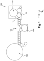
- the installation 100 mainly comprises an oven (not shown), a molding machine 110, a labeling machine 120 and a filling machine 130.
- the oven is intended to thermally condition the hollow body of the preforms which are then introduced into molds of the molding machine 110 in which their transformation by blow molding or by stretch-blow molding into containers is carried out.
- the containers obtained are transferred to the labeling machine 120 then to the filling machine 130.
- the labeling machine 120 is arranged downstream of the container filling machine 130 as illustrated by the figure 1 of the document FR-2.972.671 .
- such an installation 100 comprises a system 10 for conveying objects consisting of preforms and then containers manufactured from said preforms.
- preforms and containers are identical objects to be conveyed because they have the same neck.
- the neck is generally provided with a collar that extends radially outward, at the junction of the neck and the hollow body.
- object therefore designates indifferently a preform or a container.
- the object When conveyed by such a system 10 through the installation 100, the object is either supported by means of such a collar, or gripped by the neck by a clamp, for example at the level of an annular groove located vertically above the collar.
- the conveying system 10 comprises a plurality of conveying devices which are arranged to successively transport said objects through the manufacturing installation 100.
- the conveying system 10 comprises rotary type conveying devices, shown schematically for this reason on the figure 1 by circles.
- the conveying devices of the system 10 are capable of ensuring the conveying of the preforms then of the containers forming said objects provided with a neck and comprising a hollow body.
- each device of the conveying system 10 is driven in rotation by a motor which is electronically controlled synchronously.
- the devices are driven in rotation around a vertical axis by motorized drive means, which is why said conveying devices are also called “wheels”.
- the first type of conveying device comprises at least one circumferentially movable plate provided with a plurality of notches having, for example, a “U” shape radially open towards the outside.
- the second type of conveying device comprises at least one movable wheel provided with a plurality of transfer arms which are each equipped at their free end with a clamp comprising two jaws.
- grippers There are different types of grippers depending in particular on the part of the object with which the gripper jaws cooperate. We thus distinguish grippers according to whether the jaws are positioned below the radial collar of the neck of the object or whether the jaws ensure gripping with a clamping force of the neck above the collar.
- the jaws are for example fixed to a free end of the levers of a clamp.
- the jaws are mounted movable between at least one open position and one closed position
- the open position corresponds to a position in which the object can be introduced or extracted from an opening delimited by the jaws in the closed position.
- the jaws of the clamp are usually automatically returned by return means, such as a spring, to the closed position.
- clamps in which the object is forcibly inserted between or outside the jaws, and other clamps in which at least the opening is controlled by means of a mechanism, for example an actuating mechanism of the cam and roller type.
- the conveying system 10 comprises at least a first conveying device 12 and a second device 14 for conveying objects, respectively referred to hereinafter as first wheel 12 and second wheel 14.
- the first wheel 12 is arranged downstream of the molding machine 110, here directly at the outlet, and the second wheel 14 is located immediately downstream of the first wheel 12.
- the objects conveyed by the first wheel 12 and the second wheel 14 therefore consist of containers, for example bottles.
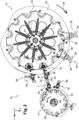
- the first wheel 12 is provided with a plurality of transfer arms 16 which are distributed circumferentially in a regular manner on a rotating plate 18.
- Each transfer arm 16 is equipped with a clamp 20 for gripping at least one object, here a container.
- the gripper 20 takes a container in a mold (not shown) along a carousel of the blowing machine 110 and brings this container into an arm of the second wheel 14, as illustrated in figure 1 .
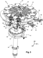
- the arm 16 pivots along a first cam path visible in figure 3 and the clamp 20 is movable in translation along the arm 16 following an external cam edge visible in figure 3 .
- the arm 16 pivots along a first cam path visible in figure 3 and the clamp 20 is movable in translation along the arm 16 following an external cam edge visible in figure 3 .
- first wheel 12 and the second wheel 14 may be located at any location along an object conveyance path, particularly when this conveyance of the objects is carried out continuously and during which each object is held individually.
- the clamp 20 comprises two jaws 22 which are mounted to move between an open position and a closed position.
- the clamp 20 comprises means for elastically returning the jaws to the closed position and a mechanism 24 to selectively control the clamp 20 in the open position, against said elastic return means.
- the mechanism 24 for controlling the opening of the clamp 20 comprises at least one roller 26 which is intended to cooperate with a cam 28.
- the first wheel 12 is driven around a first axis A1 of rotation by first drive means 30 comprising at least one motor (not shown).
- the cam 28 is for example integral with a support plate 32 which is fixed relative to the movable plate 18 comprising the transfer arms 16 and driven in rotation by the first drive means 30.
- the second wheel 14 is similar in design to the first wheel 12.
- the second wheel 14 is provided with a plurality of transfer arms 34 each equipped with a clamp 36 for gripping at least one container forming here said object conveyed in this part of the installation by the conveying system 10.
- the second wheel 14 comprises a movable plate 38 to which the transfer arms 34 are linked in movement.
- the second wheel 14 is driven by second drive means 40 around a second axis A2 of rotation, the second wheel 14 being driven in a direction of rotation opposite to that of the first wheel 12.
- the second wheel 14 comprises a support plate 42 fixed relative to the plate 38 driven in rotation.
- the first drive means 30 and the second drive means 40 respectively motorized are electronically synchronized to operate, at the transfer point T, a gripper-type transfer of the containers from the first wheel 12 to the second wheel 14 located downstream.
- the conveying system 10 comprises at least one ejection device 44 which is arranged upstream of the transfer point T.
- the ejection device 44 is carried by the first wheel 12, for example fixed to the plate 18.
- the ejection device 44 is selectively controlled in the event of desynchronization between the first drive means 30 and the second drive means 40, in particular following a power supply problem.
- the ejection device 44 has the function of ejecting, in the event of desynchronization, the containers conveyed by the first transfer wheel 12 so as to avoid any damage to the clamps 20 and/or the clamps 36 in the vicinity of the transfer point T.
- Damage to the clamps is particularly likely to occur in the event of an impact between the neck of a container conveyed by a clamp 20 of one of the transfer arms 16 of the first wheel 12 and a clamp 36 of one of the transfer arms 34 of the second wheel 14, out of sync with the first wheel 12.
- the ejection device 44 is selectively controlled between a passive state occupied when the first drive means 30 and the second drive means 40 are synchronized and an active ejection state occupied only when the first drive means 30 and the second drive means 40 are desynchronized.
- the ejection device 44 comprises ejection means 46 which are mounted to move between at least one passive position and one active ejection position corresponding to said states.
- the passive position corresponds to a position in which said ejection means 46 do not interfere with the conveying of the containers by the first transfer wheel 12.
- the active ejection position corresponds to a position in which said ejection means 46 intervene to cause the ejection of the containers conveyed by the first transfer wheel 12.
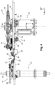
- the ejection device 44 comprises means 48 for actuating the ejection means 46 to move them into at least one of said passive and active ejection positions.
- the actuating means 48 are controlled to maintain the ejection means 46 in the passive position which are automatically returned to the active ejection position.
- the means 48 for actuating the ejection device 44 consist of at least one pneumatic cylinder.
- the pneumatic cylinder is for example associated with a distributor in order to be selectively controlled and automatically returned to the active ejection position.
- the actuating means 48 may also comprise elastic return means such as a spring.
- the ejection device 44 comprises ejection means 46 which are arranged upstream of the transfer point T in order to come into contact with the containers conveyed by the first wheel 12 and to then systematically cause the ejection of each container from the clamp 20 of the transfer arm 16 of the first wheel 12.
- the ejection means 46 comprise at least one ejection member 50 which is formed by at least one saber.
- the ejection member 50 formed by said at least one saber is moved in translation between said passive and active ejection positions by the cylinder forming the actuating means 48.
- the ejection member 50 is in the active ejection position deployed on the path of the containers and arranged vertically at a determined height to come into contact with the containers in the vicinity of the neck.
- the ejection means 46 comprise more than one ejection member 50, for example at least one other saber offset vertically downwards relative to the first saber and intended to come into contact with the body of the containers.
- the container conveyed by the clamp 20 therefore strikes the blade forming the ejection member 50, which will cause it to be ejected from the jaws 22 of the clamp 20, which open under the effect of the impact, thus releasing the container.
- the container ejected by the sabre then falls by gravity preferably into collection means, such as bins, arranged to recover the ejected containers, in particular in order to facilitate their subsequent evacuation.
- the ejection device 44 advantageously constitutes only one of the ejection devices associated with the first wheel 12.
- the first wheel 12 of the system 10 comprises at least one other ejection device 52, called second, which is arranged upstream of the first ejection device 44.
- the second ejection device 52 has a different function from that of the first ejection device 44 intended to intervene in the event of desynchronization.
- the second ejection device 52 is controlled to selectively eliminate at least one object, preform or container, depending on other determined conditions.
- the second ejection device 52 is notably used in the event of a defect detected on a container requiring its elimination due to non-conformity or to take a sample for quality control purposes of the manufactured container.
- the second ejection device 52 is identical to the first ejection device 44 and comprises at least one ejection saber 54.
- the saber 54 forming the ejection member is thus moved in translation between said passive and active positions by actuating means 56, such as a jack.
- the system comprises at least one systematic ejection device (58), which is arranged downstream of the transfer point T to systematically eject any container conveyed by the first wheel 12.
- the systematic ejection device 58 is intended to prevent any return of a container conveyed by the first wheel 12 downstream of the transfer point T, such as a container not transferred to the second wheel 14 or not ejected by said first ejection device 44.
- the systematic ejection device 58 prevents a gripper returning to a mold from still being occupied by a container instead of being available to grab a newly blown container.
- Such a systematic ejection device 58 may be a third ejection device 58 added to the first ejection device 44 and to the second ejection device 52.
- the systematic ejection device 58 may be another ejection device 58 added to the ejection device 44.
- the third ejection device 58 comprises at least one ejection member 60 which is arranged in a fixed manner relative to the first transfer wheel 12 to prevent any return of the container.
- the third ejection device 58 is integral with the first wheel 12 of the conveying system 10.
- the ejection member 60 is a fixed saber which is arranged to systematically eject all containers present from the clamp 20 of a transfer arm 16 of the first wheel 12.
- the ejection member 60 of the third ejection device 58 is arranged vertically in height to come into contact with the container near the neck.
- the first ejection device 44 is arranged as close as possible to the transfer point T so as to eject all of the containers upstream in the event of desynchronization.
- the first ejection device 44 is preferably arranged upstream of the transfer point T.
- a compromise consists of maintaining a reduced use of capacitors, the number of which will be determined in particular according to the angular sector to be covered between the first ejection device 44 and the transfer point T, the number of containers that can be inserted and cause damage to the clamps.
- the ejection device 44 comprises ejection means 46 which are capable of causing the opening of at least one clamp 20 to obtain the ejection of the conveyed object, preform or container, from the clamp 20 of the transfer arm 34 of the first wheel 12.
- the ejection means 46 comprise at least one ejection member 50 which is formed by a cam.
- the cam forming the ejection member 50 is capable of acting on the control mechanism 24 of one or more clamps 20 to cause them to open in order to eject the objects, preforms or containers, which will then fall by gravity.
- the cam is mounted to move between a passive position and an active ejection position and controlled in movement in at least one of said positions by means of actuating means 48.
- the cam is configured to cause the clamp 20 to open, if necessary against means for returning the jaws 22 of the clamp to a closed position.
Landscapes
- Engineering & Computer Science (AREA)
- Mechanical Engineering (AREA)
- Specific Conveyance Elements (AREA)
Claims (10)
- System (10) zur Förderung von Gegenständen aus thermoplastischem Material mit einem Hohlkörper mit einem Hals, wobei das System (10) wenigstens Folgendes beinhaltet:- ein erstes Rad (12), das mit Übergabearmen (16) versehen ist, die jeweils mit einer Zange (20) zum Greifen eines Gegenstands ausgerüstet sind, und von ersten Antriebsmitteln (30) um eine erste Drehachse (A1) angetrieben wird, und- ein zweites Rad (14), das mit Übergabearmen (34) versehen ist, die jeweils mit einer Zange (36) zum Greifen eines Gegenstands ausgerüstet sind, und von zweiten Antriebsmitteln (40) um eine zweite Drehachse (A2) angetrieben wird, wobei das zweite Rad (14) in einer Richtung angetrieben wird, die der des ersten Rads (12) entgegengesetzt ist,wobei das System eine Konfiguration zur Synchronisation zwischen den ersten und zweiten Antriebsmitteln (30, 40) aufweist, wobei die ersten Antriebsmittel (30) und die zweiten Antriebsmittel (40) jeweils motorgetrieben sind und von einer Steuereinheit angesteuert werden, die dazu ausgebildet ist, das System elektronisch in die Synchronisationskonfiguration zu bringen und darin zu halten, um an einem bestimmten Übergabepunkt (T) eine Zange-zu-Zange-Übergabe eines Gegenstands vom ersten Rad (12) zum zweiten Rad (14), das sich stromab befindet, vorzunehmen,dadurch gekennzeichnet, dass das System (10) wenigstens eine Auswurfvorrichtung (44) beinhaltet, die, angeordnet stromauf des Übergabepunkts (T) und Auswurfmittel (46) umfassend, im Falle einer Desynchronisation zwischen den ersten und zweiten Antriebsmitteln (30, 40) selektiv gesteuert wird, damit die Auswurfmittel (46) mit wenigstens einem Gegenstand, der vom ersten Rad (12) gefördert wird, in Kontakt treten, um dessen Auswurf aus der Zange (20) des Übergabearms (16) des ersten Rads (12) zu bewirken, um jegliche Beschädigung der Zangen (20, 36) in der Nähe des Übergabepunkts (T) zu vermeiden.
- System nach Anspruch 1, dadurch gekennzeichnet, dass die Auswurfmittel (46) zwischen wenigstens folgenden Positionen beweglich angebracht sind:- einer passiven Position, in der die Auswurfmittel (46) das Fördern der Gegenstände durch das erste Übergaberad (12) nicht stören, und- einer aktiven Auswurfposition, in der die Auswurfmittel (46) eingreifen, um den Auswurf der Gegenstände, die vom ersten Übergaberad (12) gefördert werden, zu bewirken.
- System nach Anspruch 2, dadurch gekennzeichnet, dass die Auswurfvorrichtung (44) Mittel (48) zur Betätigung der Auswurfmittel (46) beinhaltet, um sie in die passive Position und/oder in die aktive Auswurfposition zu bewegen.
- System nach Anspruch 3, dadurch gekennzeichnet, dass die Betätigungsmittel (48) gesteuert werden, um die Auswurfmittel (46) in der passiven Position zu halten, und dadurch, dass die Auswurfmittel (46) automatisch in die aktive Auswurfposition zurückgestellt werden.
- System nach einem der Ansprüche 1 bis 4, dadurch gekennzeichnet, dass die Auswurfmittel (46) wenigstens ein Auswurforgan (50) beinhalten, das vertikal angeordnet ist, um mit dem wenigstens einen Gegenstand in der Nähe des Halses in Kontakt zu treten.
- System nach einem der vorhergehenden Ansprüche, dadurch gekennzeichnet, dass die Auswurfvorrichtung (44) zusätzliche Auswurfmittel (46) beinhaltet, die geeignet sind, die Öffnung wenigstens einer Zange (20) zu bewirken, um den Auswurf des geförderten Gegenstands aus der Zange (20) des Übergabearms (16) des ersten Rads (12) zu erreichen.
- System nach Anspruch 6, dadurch gekennzeichnet, dass die zusätzlichen Auswurfmittel (46) wenigstens ein Auswurforgan (50) beinhalten, das geeignet ist, auf wenigstens einen Mechanismus (24) zur Steuerung einer Zange (20) zu wirken, um deren Öffnung zu bewirken.
- System nach einem der vorhergehenden Ansprüche, dadurch gekennzeichnet, dass die Auswurfvorrichtung (44) eine erste Auswurfvorrichtung ist, wobei das System (10) wenigstens eine zweite Auswurfvorrichtung (52) beinhaltet, die stromauf der ersten Auswurfvorrichtung (44) angeordnet ist.
- System nach einem der vorhergehenden Ansprüche, dadurch gekennzeichnet, dass das System (10) eine Vorrichtung (58) zum systematischen Auswurf beinhaltet, die stromab des Übergabepunkts (T) angeordnet ist, um jedes Objekt, das vom ersten Rad (12) über den Übergabepunkt (T) hinweg gefördert wird, systematisch auszuwerfen.
- Verfahren zur Förderung von Gegenständen aus thermoplastischem Material mit einem Hohlkörper mit einem Hals, wobei bei dem Verfahren ein erster Förderer mit einer Mehrzahl von ersten Mitteln zum einzelnen Greifen der Gegenstände, die einen ersten Förderweg entlang zu fördern sind, und ein zweiter Förderer mit einer Mehrzahl von zweiten Mitteln zum einzelnen Greifen der Gegenstände, die einen zweiten Förderweg entlang zu fördern sind, der den ersten Förderweg an einem Übergabepunkt (T) tangiert, verwendet wird, wobei das Verfahren einen Schritt des synchronisierten Betriebs umfasst, bei dem jedes der ersten Greifmittel, das am Übergabepunkt (T) eintrifft, mit einem zweiten, ergänzenden Übergabemittel zusammenwirkt, um einen Gegenstand vom ersten Greifmittel an das zweite Greifmittel zu übergeben, dadurch gekennzeichnet, dass es einen Schritt des desynchronisierten Betriebs umfasst, bei dem die Gegenstände aus den ersten Greifmitteln ausgeworfen werden, bevor sie am Übergabepunkt (T) eintreffen, mittels des Systems nach einem der Ansprüche 1 bis 9.
Applications Claiming Priority (2)
| Application Number | Priority Date | Filing Date | Title |
|---|---|---|---|
| FR1660848A FR3058404B1 (fr) | 2016-11-09 | 2016-11-09 | Systeme de convoyage d'objets en matiere thermoplastique comportant un corps creux muni d'un col |
| PCT/FR2017/053035 WO2018046874A2 (fr) | 2016-11-09 | 2017-11-07 | Systeme de convoyage d'objets en matiere thermoplastique comportant un corps creux muni d'un col |
Publications (2)
| Publication Number | Publication Date |
|---|---|
| EP3538459A2 EP3538459A2 (de) | 2019-09-18 |
| EP3538459B1 true EP3538459B1 (de) | 2025-01-08 |
Family
ID=57861062
Family Applications (1)
| Application Number | Title | Priority Date | Filing Date |
|---|---|---|---|
| EP17808535.3A Active EP3538459B1 (de) | 2016-11-09 | 2017-11-07 | System zum befördern von gegenständen aus einem thermoplastischen material mit einem hohlkörper mit einem hals |
Country Status (4)
| Country | Link |
|---|---|
| EP (1) | EP3538459B1 (de) |
| CN (1) | CN109963798B (de) |
| FR (1) | FR3058404B1 (de) |
| WO (1) | WO2018046874A2 (de) |
Families Citing this family (5)
| Publication number | Priority date | Publication date | Assignee | Title |
|---|---|---|---|---|
| DE102019106075A1 (de) | 2019-03-11 | 2020-09-17 | Khs Gmbh | Transportvorrichtung und Verfahren zum um eine vertikale Maschinenachse umlaufenden Transport von Behältern |
| CN110790209A (zh) * | 2019-11-29 | 2020-02-14 | 苏州工业职业技术学院 | 一种酱料生产线自动灌装系统及其控制方法 |
| JP7603964B2 (ja) * | 2020-11-17 | 2024-12-23 | 株式会社Ilファーマパッケージング | 物品選別装置 |
| DE102021122324A1 (de) * | 2021-08-30 | 2023-03-02 | Krones Aktiengesellschaft | Ausschleuseeinrichtung zum Ausschleusen von Behältnissen mit Kniehebelsystem |
| CN114620284B (zh) * | 2022-03-15 | 2023-02-03 | 江苏国盛新材料有限公司 | 一种铈钛粉体快速罐装机及其罐装工艺 |
Citations (10)
| Publication number | Priority date | Publication date | Assignee | Title |
|---|---|---|---|---|
| EP1251085A1 (de) * | 2001-04-19 | 2002-10-23 | Dai Nippon Printing Co., Ltd. | Fördersystem für Gefässe |
| JP2008044768A (ja) * | 2006-08-21 | 2008-02-28 | Shibuya Kogyo Co Ltd | 容器搬送システムおよび容器搬送システムの容器リジェクト方法 |
| EP1970329A1 (de) * | 2007-03-15 | 2008-09-17 | Shibuya Kogyo Co., Ltd. | Artikelfördervorrichtung |
| DE102008014534A1 (de) | 2008-03-15 | 2009-09-17 | Krones Ag | Anlage und Verfahren zum Abfüllen von Getränkebehältern |
| DE102008021527A1 (de) | 2008-04-30 | 2009-11-05 | Krones Ag | Anlage und Verfahren zur Herstellung von Behältern |
| EP2292550A1 (de) | 2009-09-07 | 2011-03-09 | Krones AG | Vorrichtung und Verfahren zum Herstellen von Kunststoffflaschen |
| EP2511205A2 (de) | 2011-04-13 | 2012-10-17 | Krones AG | Behälterbehandlungsmaschine und Verfahren zur Behälterbehandlung |
| EP2641721A1 (de) * | 2012-03-20 | 2013-09-25 | Krones AG | Verfahren und Vorrichtung zum Behandeln von Kunststoffbehältnissen mit Zeitreduzierung beim Synchronisieren von Anlagenteilen |
| JP2015067333A (ja) * | 2013-09-30 | 2015-04-13 | 澁谷工業株式会社 | 充填装置および充填方法 |
| DE102015000631A1 (de) | 2015-01-22 | 2016-07-28 | Khs Corpoplast Gmbh | Vorrichtung und Verfahren zum Transport von Vorformlingen im Bereich einer Blasmaschine |
Family Cites Families (10)
| Publication number | Priority date | Publication date | Assignee | Title |
|---|---|---|---|---|
| FR2479077A1 (fr) | 1980-03-26 | 1981-10-02 | Pont A Mousson | Installation de fabrication de corps creux par conditionnement thermique puis soufflage de preformes en matiere plastique |
| FR2774666B1 (fr) | 1998-02-12 | 2000-04-07 | Sidel Sa | Dispositif de transfert pour corps creux possedant un goulot |
| DE19922873A1 (de) * | 1999-05-19 | 2000-11-23 | Krones Ag | Vorrichtung zum Einbringen und/oder Ausbringen von Behältern |
| JP4617592B2 (ja) * | 2001-03-30 | 2011-01-26 | 澁谷工業株式会社 | 樹脂容器搬送システム |
| US7364043B2 (en) * | 2003-12-30 | 2008-04-29 | Zen Voce Manufacturing Pte Ltd | Fastener inspection system |
| JP4906058B2 (ja) * | 2006-02-27 | 2012-03-28 | 株式会社 東京ウエルズ | ワーク搬送システム |
| MX2009001443A (es) * | 2006-08-07 | 2009-04-08 | Sacmi | Aparatos y metodo. |
| FR2915475B1 (fr) | 2007-04-30 | 2009-07-31 | Sidel Participations | Dispositif de transfert et installation de type lineaire pour la fabrication de recipients |
| FR2972671B1 (fr) | 2011-03-17 | 2014-07-11 | Sidel Participations | Dispositif de transfert comportant une pince de prehension perfectionnee |
| DE102013007385A1 (de) * | 2013-04-30 | 2014-10-30 | Theegarten-Pactec Gmbh & Co. Kg | Steuerungseinrichtung für Produkt-Halteeinrichtungen und Verpackungsmaschine mit einer solchen |
-
2016
- 2016-11-09 FR FR1660848A patent/FR3058404B1/fr active Active
-
2017
- 2017-11-07 CN CN201780069236.2A patent/CN109963798B/zh active Active
- 2017-11-07 EP EP17808535.3A patent/EP3538459B1/de active Active
- 2017-11-07 WO PCT/FR2017/053035 patent/WO2018046874A2/fr not_active Ceased
Patent Citations (10)
| Publication number | Priority date | Publication date | Assignee | Title |
|---|---|---|---|---|
| EP1251085A1 (de) * | 2001-04-19 | 2002-10-23 | Dai Nippon Printing Co., Ltd. | Fördersystem für Gefässe |
| JP2008044768A (ja) * | 2006-08-21 | 2008-02-28 | Shibuya Kogyo Co Ltd | 容器搬送システムおよび容器搬送システムの容器リジェクト方法 |
| EP1970329A1 (de) * | 2007-03-15 | 2008-09-17 | Shibuya Kogyo Co., Ltd. | Artikelfördervorrichtung |
| DE102008014534A1 (de) | 2008-03-15 | 2009-09-17 | Krones Ag | Anlage und Verfahren zum Abfüllen von Getränkebehältern |
| DE102008021527A1 (de) | 2008-04-30 | 2009-11-05 | Krones Ag | Anlage und Verfahren zur Herstellung von Behältern |
| EP2292550A1 (de) | 2009-09-07 | 2011-03-09 | Krones AG | Vorrichtung und Verfahren zum Herstellen von Kunststoffflaschen |
| EP2511205A2 (de) | 2011-04-13 | 2012-10-17 | Krones AG | Behälterbehandlungsmaschine und Verfahren zur Behälterbehandlung |
| EP2641721A1 (de) * | 2012-03-20 | 2013-09-25 | Krones AG | Verfahren und Vorrichtung zum Behandeln von Kunststoffbehältnissen mit Zeitreduzierung beim Synchronisieren von Anlagenteilen |
| JP2015067333A (ja) * | 2013-09-30 | 2015-04-13 | 澁谷工業株式会社 | 充填装置および充填方法 |
| DE102015000631A1 (de) | 2015-01-22 | 2016-07-28 | Khs Corpoplast Gmbh | Vorrichtung und Verfahren zum Transport von Vorformlingen im Bereich einer Blasmaschine |
Non-Patent Citations (14)
| Title |
|---|
| ANONYMOUS: "Krones Contiform Bloc Streckblasmaschine und Füller in starker Kombination", KRONES CONTIFORM BLOC, KRONES AG, 1 October 2012 (2012-10-01), pages 1 - 101, XP093325691, Retrieved from the Internet <URL:https://web.archive.org/web/20130603055208/http://www.krones.com/downloads/contiformbloc_de.pdf> |
| BIERSCHNEIDER STEFAN: "Wasser aus dem Herzen Umbriens - Neue Technologie für den italienischen Mineralbrunnen Tione", KRONES-MAGAZIN, KRONES AG, vol. 2010, no. 4, 1 January 2010 (2010-01-01), pages 20 - 27, XP093325716 |
| D10 - Technische Dokumentation Funktionsbeschreibung F7 |
| D11 - Serviceanleitung Krones Ergbobloc-L, Stand 05/2009 |
| D12 - Präsentation „Evolution of a revolution - The Bloc", veröffentlicht 2014 |
| D12a - Handzettel zur D12 |
| D13 - Eidesstattliche Versicherung von Herr Jürgen Koller |
| D13 - Präsentation ErgoBloc L – Übersicht, veröffentlicht 2012 |
| D15 - Eidesstattliche Versicherung von Herr Ludovic Lainé |
| D16 - Hallenplan der Halle B6 der Drinktec 2009 |
| D18 - Anlagenkonvolut (VB1) |
| D8 - Video zur Erklärung des „Servo Joint Control"-Systems von Krones (Video in the Blob) |
| D9 - Video zum Antriebskonzept des „Servo Joint Control"-Systems von Krones (Video in the Blob) |
| KRONES AG: "Krones ErgoBloc L bei Tione, Italien", 11 May 2010 (2010-05-11), XP093325717, Retrieved from the Internet <URL:https://www.youtube.com/watch?v=4VcktQXhJ8I> |
Also Published As
| Publication number | Publication date |
|---|---|
| FR3058404B1 (fr) | 2020-09-18 |
| WO2018046874A3 (fr) | 2018-05-03 |
| EP3538459A2 (de) | 2019-09-18 |
| CN109963798B (zh) | 2021-07-13 |
| WO2018046874A2 (fr) | 2018-03-15 |
| CN109963798A (zh) | 2019-07-02 |
| FR3058404A1 (fr) | 2018-05-11 |
Similar Documents
| Publication | Publication Date | Title |
|---|---|---|
| EP3538459B1 (de) | System zum befördern von gegenständen aus einem thermoplastischen material mit einem hohlkörper mit einem hals | |
| EP2686259B1 (de) | Übertragungsvorrichtung mit einem greifer | |
| EP1697238B1 (de) | Eine vorrichtung zum gezielten entfernen von falsch positionierten längsvorformlingen umfassende vorformlingzufuhrvorrichtung | |
| EP2341001B1 (de) | Verfahren und Maschine zur Umverpackung von Artikeln zur Bildung von Artikellosen, bestehend aus einer Vielzahl von Artikeln und einer Umverpackung aus Karton | |
| EP3239079B1 (de) | Förderanlage für hohlkörper, die ein förderband zur verteilung und satelliteneinheiten zur bearbeitung umfasst | |
| EP2499069B1 (de) | Sortiermaschine für behälter und zugehöriges verfahren | |
| EP2509769B1 (de) | Blasformmaschine und verfahren mi vorladung von vorformen | |
| FR2915475A1 (fr) | Dispositif de transfert et installation de type lineaire pour la fabrication de recipients | |
| WO2007077320A2 (fr) | Dispositif d'aiguillage de recipients | |
| WO2021122712A1 (fr) | Procede d'indexation angulaire d'une preforme | |
| EP3427917B1 (de) | Spannfuttervorrichtung zum fördern von hohlkörpern, und anlage zur herstellung von behältern | |
| EP3898176B1 (de) | Vorrichtung zum fördern von vorformen und verfahren zur steuerung solch einer vorrichtung zur winkelmässigen indexierung der vorformen in einer referenzposition | |
| FR2801045A1 (fr) | Systeme de convoyage d'entites discretes comportant un dispositif de repartition et installation de soufflage de recipients munie d'un tel systeme | |
| EP1922272B1 (de) | Vorrichtung zum laden von behältern auf ein transportelement mit mittel zum auswurf falsch geladener behälter | |
| EP3891087B1 (de) | Vorrichtung, anlage und verfahren zum ausstossen von produkten | |
| WO2019234364A1 (fr) | Installation de production de recipients a arret d'urgence selectif | |
| FR3082138A1 (fr) | Installation de production de recipients a arret d'urgence progressif | |
| EP3898175B1 (de) | Vorrichtung zum fördern von vorformlingen für einen ofen und verfahren zur steuerung einer solchen vorrichtung | |
| WO2020128324A1 (fr) | Procédé et système de traitement d'un flux de préformes en matière thermoplastique pour en orienter angulairement chacune des préformes dans une position de référence | |
| EP4594079A1 (de) | Verfahren zum überführen von vorformlingen auf einen förderer | |
| EP3546194B1 (de) | Fördervorrichtung, die mit einem sicherheitssystem ausgestattet ist | |
| FR3094007A1 (fr) | Dispositif de regroupement de produits |
Legal Events
| Date | Code | Title | Description |
|---|---|---|---|
| STAA | Information on the status of an ep patent application or granted ep patent |
Free format text: STATUS: UNKNOWN |
|
| STAA | Information on the status of an ep patent application or granted ep patent |
Free format text: STATUS: THE INTERNATIONAL PUBLICATION HAS BEEN MADE |
|
| PUAI | Public reference made under article 153(3) epc to a published international application that has entered the european phase |
Free format text: ORIGINAL CODE: 0009012 |
|
| STAA | Information on the status of an ep patent application or granted ep patent |
Free format text: STATUS: REQUEST FOR EXAMINATION WAS MADE |
|
| 17P | Request for examination filed |
Effective date: 20190429 |
|
| AK | Designated contracting states |
Kind code of ref document: A2 Designated state(s): AL AT BE BG CH CY CZ DE DK EE ES FI FR GB GR HR HU IE IS IT LI LT LU LV MC MK MT NL NO PL PT RO RS SE SI SK SM TR |
|
| AX | Request for extension of the european patent |
Extension state: BA ME |
|
| DAV | Request for validation of the european patent (deleted) | ||
| DAX | Request for extension of the european patent (deleted) | ||
| STAA | Information on the status of an ep patent application or granted ep patent |
Free format text: STATUS: EXAMINATION IS IN PROGRESS |
|
| 17Q | First examination report despatched |
Effective date: 20221013 |
|
| GRAP | Despatch of communication of intention to grant a patent |
Free format text: ORIGINAL CODE: EPIDOSNIGR1 |
|
| STAA | Information on the status of an ep patent application or granted ep patent |
Free format text: STATUS: GRANT OF PATENT IS INTENDED |
|
| RIC1 | Information provided on ipc code assigned before grant |
Ipc: B65G 47/82 20060101ALN20241003BHEP Ipc: B67C 7/00 20060101ALI20241003BHEP Ipc: B65G 47/86 20060101AFI20241003BHEP |
|
| GRAS | Grant fee paid |
Free format text: ORIGINAL CODE: EPIDOSNIGR3 |
|
| INTG | Intention to grant announced |
Effective date: 20241105 |
|
| GRAA | (expected) grant |
Free format text: ORIGINAL CODE: 0009210 |
|
| STAA | Information on the status of an ep patent application or granted ep patent |
Free format text: STATUS: THE PATENT HAS BEEN GRANTED |
|
| AK | Designated contracting states |
Kind code of ref document: B1 Designated state(s): AL AT BE BG CH CY CZ DE DK EE ES FI FR GB GR HR HU IE IS IT LI LT LU LV MC MK MT NL NO PL PT RO RS SE SI SK SM TR |
|
| REG | Reference to a national code |
Ref country code: GB Ref legal event code: FG4D Free format text: NOT ENGLISH |
|
| REG | Reference to a national code |
Ref country code: CH Ref legal event code: EP |
|
| REG | Reference to a national code |
Ref country code: DE Ref legal event code: R096 Ref document number: 602017087264 Country of ref document: DE |
|
| P01 | Opt-out of the competence of the unified patent court (upc) registered |
Free format text: CASE NUMBER: APP_67983/2024 Effective date: 20241224 |
|
| REG | Reference to a national code |
Ref country code: IE Ref legal event code: FG4D Free format text: LANGUAGE OF EP DOCUMENT: FRENCH |
|
| REG | Reference to a national code |
Ref country code: LT Ref legal event code: MG9D |
|
| REG | Reference to a national code |
Ref country code: NL Ref legal event code: MP Effective date: 20250108 |
|
| REG | Reference to a national code |
Ref country code: AT Ref legal event code: MK05 Ref document number: 1758204 Country of ref document: AT Kind code of ref document: T Effective date: 20250108 |
|
| PG25 | Lapsed in a contracting state [announced via postgrant information from national office to epo] |
Ref country code: NL Free format text: LAPSE BECAUSE OF FAILURE TO SUBMIT A TRANSLATION OF THE DESCRIPTION OR TO PAY THE FEE WITHIN THE PRESCRIBED TIME-LIMIT Effective date: 20250108 |
|
| PG25 | Lapsed in a contracting state [announced via postgrant information from national office to epo] |
Ref country code: RS Free format text: LAPSE BECAUSE OF FAILURE TO SUBMIT A TRANSLATION OF THE DESCRIPTION OR TO PAY THE FEE WITHIN THE PRESCRIBED TIME-LIMIT Effective date: 20250408 |
|
| PG25 | Lapsed in a contracting state [announced via postgrant information from national office to epo] |
Ref country code: FI Free format text: LAPSE BECAUSE OF FAILURE TO SUBMIT A TRANSLATION OF THE DESCRIPTION OR TO PAY THE FEE WITHIN THE PRESCRIBED TIME-LIMIT Effective date: 20250108 |
|
| PG25 | Lapsed in a contracting state [announced via postgrant information from national office to epo] |
Ref country code: PL Free format text: LAPSE BECAUSE OF FAILURE TO SUBMIT A TRANSLATION OF THE DESCRIPTION OR TO PAY THE FEE WITHIN THE PRESCRIBED TIME-LIMIT Effective date: 20250108 |
|
| PG25 | Lapsed in a contracting state [announced via postgrant information from national office to epo] |
Ref country code: ES Free format text: LAPSE BECAUSE OF FAILURE TO SUBMIT A TRANSLATION OF THE DESCRIPTION OR TO PAY THE FEE WITHIN THE PRESCRIBED TIME-LIMIT Effective date: 20250108 |
|
| PG25 | Lapsed in a contracting state [announced via postgrant information from national office to epo] |
Ref country code: IS Free format text: LAPSE BECAUSE OF FAILURE TO SUBMIT A TRANSLATION OF THE DESCRIPTION OR TO PAY THE FEE WITHIN THE PRESCRIBED TIME-LIMIT Effective date: 20250508 Ref country code: NO Free format text: LAPSE BECAUSE OF FAILURE TO SUBMIT A TRANSLATION OF THE DESCRIPTION OR TO PAY THE FEE WITHIN THE PRESCRIBED TIME-LIMIT Effective date: 20250408 |
|
| PG25 | Lapsed in a contracting state [announced via postgrant information from national office to epo] |
Ref country code: HR Free format text: LAPSE BECAUSE OF FAILURE TO SUBMIT A TRANSLATION OF THE DESCRIPTION OR TO PAY THE FEE WITHIN THE PRESCRIBED TIME-LIMIT Effective date: 20250108 |
|
| PG25 | Lapsed in a contracting state [announced via postgrant information from national office to epo] |
Ref country code: LV Free format text: LAPSE BECAUSE OF FAILURE TO SUBMIT A TRANSLATION OF THE DESCRIPTION OR TO PAY THE FEE WITHIN THE PRESCRIBED TIME-LIMIT Effective date: 20250108 Ref country code: PT Free format text: LAPSE BECAUSE OF FAILURE TO SUBMIT A TRANSLATION OF THE DESCRIPTION OR TO PAY THE FEE WITHIN THE PRESCRIBED TIME-LIMIT Effective date: 20250508 |
|
| PG25 | Lapsed in a contracting state [announced via postgrant information from national office to epo] |
Ref country code: BG Free format text: LAPSE BECAUSE OF FAILURE TO SUBMIT A TRANSLATION OF THE DESCRIPTION OR TO PAY THE FEE WITHIN THE PRESCRIBED TIME-LIMIT Effective date: 20250108 Ref country code: GR Free format text: LAPSE BECAUSE OF FAILURE TO SUBMIT A TRANSLATION OF THE DESCRIPTION OR TO PAY THE FEE WITHIN THE PRESCRIBED TIME-LIMIT Effective date: 20250409 |
|
| PG25 | Lapsed in a contracting state [announced via postgrant information from national office to epo] |
Ref country code: AT Free format text: LAPSE BECAUSE OF FAILURE TO SUBMIT A TRANSLATION OF THE DESCRIPTION OR TO PAY THE FEE WITHIN THE PRESCRIBED TIME-LIMIT Effective date: 20250108 |
|
| PG25 | Lapsed in a contracting state [announced via postgrant information from national office to epo] |
Ref country code: SE Free format text: LAPSE BECAUSE OF FAILURE TO SUBMIT A TRANSLATION OF THE DESCRIPTION OR TO PAY THE FEE WITHIN THE PRESCRIBED TIME-LIMIT Effective date: 20250108 |
|
| PG25 | Lapsed in a contracting state [announced via postgrant information from national office to epo] |
Ref country code: SM Free format text: LAPSE BECAUSE OF FAILURE TO SUBMIT A TRANSLATION OF THE DESCRIPTION OR TO PAY THE FEE WITHIN THE PRESCRIBED TIME-LIMIT Effective date: 20250108 |
|
| REG | Reference to a national code |
Ref country code: DE Ref legal event code: R026 Ref document number: 602017087264 Country of ref document: DE |
|
| PG25 | Lapsed in a contracting state [announced via postgrant information from national office to epo] |
Ref country code: DK Free format text: LAPSE BECAUSE OF FAILURE TO SUBMIT A TRANSLATION OF THE DESCRIPTION OR TO PAY THE FEE WITHIN THE PRESCRIBED TIME-LIMIT Effective date: 20250108 |
|
| PLBI | Opposition filed |
Free format text: ORIGINAL CODE: 0009260 |
|
| PG25 | Lapsed in a contracting state [announced via postgrant information from national office to epo] |
Ref country code: EE Free format text: LAPSE BECAUSE OF FAILURE TO SUBMIT A TRANSLATION OF THE DESCRIPTION OR TO PAY THE FEE WITHIN THE PRESCRIBED TIME-LIMIT Effective date: 20250108 Ref country code: CZ Free format text: LAPSE BECAUSE OF FAILURE TO SUBMIT A TRANSLATION OF THE DESCRIPTION OR TO PAY THE FEE WITHIN THE PRESCRIBED TIME-LIMIT Effective date: 20250108 |
|
| PG25 | Lapsed in a contracting state [announced via postgrant information from national office to epo] |
Ref country code: RO Free format text: LAPSE BECAUSE OF FAILURE TO SUBMIT A TRANSLATION OF THE DESCRIPTION OR TO PAY THE FEE WITHIN THE PRESCRIBED TIME-LIMIT Effective date: 20250108 |
|
| PG25 | Lapsed in a contracting state [announced via postgrant information from national office to epo] |
Ref country code: SK Free format text: LAPSE BECAUSE OF FAILURE TO SUBMIT A TRANSLATION OF THE DESCRIPTION OR TO PAY THE FEE WITHIN THE PRESCRIBED TIME-LIMIT Effective date: 20250108 |
|
| PLAX | Notice of opposition and request to file observation + time limit sent |
Free format text: ORIGINAL CODE: EPIDOSNOBS2 |
|
| 26 | Opposition filed |
Opponent name: KRONES AG Effective date: 20251008 |
|
| PGFP | Annual fee paid to national office [announced via postgrant information from national office to epo] |
Ref country code: DE Payment date: 20251022 Year of fee payment: 9 |
|
| PGFP | Annual fee paid to national office [announced via postgrant information from national office to epo] |
Ref country code: IT Payment date: 20251022 Year of fee payment: 9 |
|
| PGFP | Annual fee paid to national office [announced via postgrant information from national office to epo] |
Ref country code: FR Payment date: 20251023 Year of fee payment: 9 |