EP4074992B1 - Holzschraube - Google Patents
Holzschraube Download PDFInfo
- Publication number
- EP4074992B1 EP4074992B1 EP21191004.7A EP21191004A EP4074992B1 EP 4074992 B1 EP4074992 B1 EP 4074992B1 EP 21191004 A EP21191004 A EP 21191004A EP 4074992 B1 EP4074992 B1 EP 4074992B1
- Authority
- EP
- European Patent Office
- Prior art keywords
- shank
- outer edge
- wood screw
- ribs
- forward ribs
- Prior art date
- Legal status (The legal status is an assumption and is not a legal conclusion. Google has not performed a legal analysis and makes no representation as to the accuracy of the status listed.)
- Active
Links
Images


Classifications
-
- F—MECHANICAL ENGINEERING; LIGHTING; HEATING; WEAPONS; BLASTING
- F16—ENGINEERING ELEMENTS AND UNITS; GENERAL MEASURES FOR PRODUCING AND MAINTAINING EFFECTIVE FUNCTIONING OF MACHINES OR INSTALLATIONS; THERMAL INSULATION IN GENERAL
- F16B—DEVICES FOR FASTENING OR SECURING CONSTRUCTIONAL ELEMENTS OR MACHINE PARTS TOGETHER, e.g. NAILS, BOLTS, CIRCLIPS, CLAMPS, CLIPS OR WEDGES; JOINTS OR JOINTING
- F16B25/00—Screws that cut thread in the body into which they are screwed, e.g. wood screws
- F16B25/0036—Screws that cut thread in the body into which they are screwed, e.g. wood screws characterised by geometric details of the screw
- F16B25/0042—Screws that cut thread in the body into which they are screwed, e.g. wood screws characterised by geometric details of the screw characterised by the geometry of the thread, the thread being a ridge wrapped around the shaft of the screw
- F16B25/0068—Screws that cut thread in the body into which they are screwed, e.g. wood screws characterised by geometric details of the screw characterised by the geometry of the thread, the thread being a ridge wrapped around the shaft of the screw with multiple-threads, e.g. a double thread screws
-
- F—MECHANICAL ENGINEERING; LIGHTING; HEATING; WEAPONS; BLASTING
- F16—ENGINEERING ELEMENTS AND UNITS; GENERAL MEASURES FOR PRODUCING AND MAINTAINING EFFECTIVE FUNCTIONING OF MACHINES OR INSTALLATIONS; THERMAL INSULATION IN GENERAL
- F16B—DEVICES FOR FASTENING OR SECURING CONSTRUCTIONAL ELEMENTS OR MACHINE PARTS TOGETHER, e.g. NAILS, BOLTS, CIRCLIPS, CLAMPS, CLIPS OR WEDGES; JOINTS OR JOINTING
- F16B25/00—Screws that cut thread in the body into which they are screwed, e.g. wood screws
- F16B25/001—Screws that cut thread in the body into which they are screwed, e.g. wood screws characterised by the material of the body into which the screw is screwed
- F16B25/0015—Screws that cut thread in the body into which they are screwed, e.g. wood screws characterised by the material of the body into which the screw is screwed the material being a soft organic material, e.g. wood or plastic
-
- F—MECHANICAL ENGINEERING; LIGHTING; HEATING; WEAPONS; BLASTING
- F16—ENGINEERING ELEMENTS AND UNITS; GENERAL MEASURES FOR PRODUCING AND MAINTAINING EFFECTIVE FUNCTIONING OF MACHINES OR INSTALLATIONS; THERMAL INSULATION IN GENERAL
- F16B—DEVICES FOR FASTENING OR SECURING CONSTRUCTIONAL ELEMENTS OR MACHINE PARTS TOGETHER, e.g. NAILS, BOLTS, CIRCLIPS, CLAMPS, CLIPS OR WEDGES; JOINTS OR JOINTING
- F16B25/00—Screws that cut thread in the body into which they are screwed, e.g. wood screws
- F16B25/0036—Screws that cut thread in the body into which they are screwed, e.g. wood screws characterised by geometric details of the screw
- F16B25/0042—Screws that cut thread in the body into which they are screwed, e.g. wood screws characterised by geometric details of the screw characterised by the geometry of the thread, the thread being a ridge wrapped around the shaft of the screw
- F16B25/0047—Screws that cut thread in the body into which they are screwed, e.g. wood screws characterised by geometric details of the screw characterised by the geometry of the thread, the thread being a ridge wrapped around the shaft of the screw the ridge being characterised by its cross-section in the plane of the shaft axis
-
- F—MECHANICAL ENGINEERING; LIGHTING; HEATING; WEAPONS; BLASTING
- F16—ENGINEERING ELEMENTS AND UNITS; GENERAL MEASURES FOR PRODUCING AND MAINTAINING EFFECTIVE FUNCTIONING OF MACHINES OR INSTALLATIONS; THERMAL INSULATION IN GENERAL
- F16B—DEVICES FOR FASTENING OR SECURING CONSTRUCTIONAL ELEMENTS OR MACHINE PARTS TOGETHER, e.g. NAILS, BOLTS, CIRCLIPS, CLAMPS, CLIPS OR WEDGES; JOINTS OR JOINTING
- F16B25/00—Screws that cut thread in the body into which they are screwed, e.g. wood screws
- F16B25/10—Screws performing an additional function to thread-forming, e.g. drill screws or self-piercing screws
- F16B25/103—Screws performing an additional function to thread-forming, e.g. drill screws or self-piercing screws by means of a drilling screw-point, i.e. with a cutting and material removing action
-
- F—MECHANICAL ENGINEERING; LIGHTING; HEATING; WEAPONS; BLASTING
- F16—ENGINEERING ELEMENTS AND UNITS; GENERAL MEASURES FOR PRODUCING AND MAINTAINING EFFECTIVE FUNCTIONING OF MACHINES OR INSTALLATIONS; THERMAL INSULATION IN GENERAL
- F16B—DEVICES FOR FASTENING OR SECURING CONSTRUCTIONAL ELEMENTS OR MACHINE PARTS TOGETHER, e.g. NAILS, BOLTS, CIRCLIPS, CLAMPS, CLIPS OR WEDGES; JOINTS OR JOINTING
- F16B39/00—Locking of screws, bolts or nuts
- F16B39/22—Locking of screws, bolts or nuts in which the locking takes place during screwing down or tightening
- F16B39/28—Locking of screws, bolts or nuts in which the locking takes place during screwing down or tightening by special members on, or shape of, the nut or bolt
- F16B39/30—Locking exclusively by special shape of the screw-thread
Definitions
- the disclosure relates to a screw, more particularly to a wood screw for screwing into wood.
- TWM604844U discloses a known wood screw.
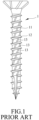
- a wood screw 1 for screwing into wood is disclosed in Taiwanese Utility Model Patent No. 301373 .
- a screw shank 11 of the wood screw 1 is provided with a plurality of spiral cutting threads 13 in the same direction as a main thread 12 thereof.
- the spiral cutting threads 13 are arranged in parallel and are spaced apart from each other in an axial direction of the screw shank 11.
- the spiral cutting threads 13 can achieve a certain degree of reduction of the resistance, due to improper design and quantity configuration of the cutting threads 13, the wood screw 1 can cause problems, such as laborious application of force, excessive damage to wood fibers, etc.
- the wood screw 1 after being screwed into the wood for a period of time, the wood screw 1 is easy to loosen in a reverse direction due to factors, such as vibration or weather, causing danger to a building structure.
- an object of the present disclosure is to provide a wood screw that has anti-cracking and anti-loosening functions.
- a wood screw of this disclosure includes a head, a shank, a main thread and a plurality of circumferentially spaced-apart forward ribs.
- the shank axially extends from the head, and has a main shank portion connected to the head, and a conical tip portion extending from the main shank portion in a direction away from the head and gradually tapering to form a conical tip end.
- the main thread protrudes from the shank and extends helically around the shank from the main shank portion to the conical tip end in a tightening direction.
- the main thread has an outer diameter ranging from 3 mm to 16 mm.
- each forward rib protrude from the shank and extend spirally around the shank from the main shank portion to the conical tip portion in a same direction as the main thread.
- the forward ribs are spaced apart from the conical tip end by a distance.
- the number of the forward ribs ranges from three to five.
- each forward rib has a first outer edge connected to the shank and facing the tightening direction, and a second outer edge connected to the first outer edge and the shank and facing opposite the tightening direction.
- the second outer edge has a length shorter than a length of the first outer edge.
- Each forward rib has a height in a radial direction of the shank smaller than a height of the main thread in the radial direction of the shank, and a lead angle greater than a lead angle of the main thread.
- a ratio of the length of said first outer edge to the length of said second outer edge ranges from 1.25 to 2.6.
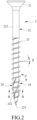
- FIGS. 2 to 4 illustrate a wood screw 2 according to the first embodiment of the present disclosure.
- the wood screw 2 is screwed into wood (not shown) along a tightening direction (A) when in use, the tightening direction (A) may be a clockwise or a counterclockwise direction
- FIG. 3 is a sectional view taken along line B-B of FIG. 2 .
- the wood screw 2 includes a head 21, a shank 22, a main thread 23, and a plurality of forward ribs 24.
- the shank 22 axially extends from the head 21, and has a main shank portion 221 connected to the head 21, and a conical tip portion 222 extending from the main shank portion 221 in a direction away from the head 21 and gradually tapering to form a conical tip end 223.
- the main thread 23 protrudes from the shank 22 and extends helically around the shank 22 from the main shank portion 221 to the conical tip end 223 in the tightening direction (A).
- the main thread 23 has an outer diameter ranging from 3 mm to 16 mm.
- a distance between the main thread 23 and the head 21 can be freely determined according to the requirement. Of course, there may be no distance between the main thread 23 and the head 21.
- the forward ribs 24 protruding from the shank 22, are circumferentially spaced apart from each other, and extend spirally around the shank 22 from a lower portion of the main shank portion 221 to the conical tip portion 222 in the same direction as the main thread 23, but are spaced apart from the conical tip end 223 by a distance.
- the forward ribs 24 are equiangularly spaced apart from each other, and each forward rib 24 extends about 150 to 270 degrees around the shank 22 in the tightening direction (A).
- the number of the forward ribs 24 is three. In other embodiments, the number of the forward ribs 24 may be four or five depending on the outer diameter of the main thread 23.
- the number of the forward ribs 24 is three; when the outer diameter of the main thread 23 is larger than 10 mm but smaller than or equal to 14 mm, the number of the forward ribs 24 is four; and when the outer diameter of the main thread 23 is larger than 14 mm but smaller than or equal to 16 mm, the number of the forward ribs 24 is five.
- Each forward rib 24 has a height (h1) in a radial direction of the shank 22 smaller than a height (h2) of the main thread 23 in the radial direction of the shank 22, and a lead angle ( ⁇ ) greater than a lead angle ( ⁇ ) of the main thread 23.
- the lead angle ( ⁇ ) is within the range of 50 to 60 degrees.
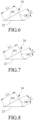
- each forward rib 24 has a first outer edge 241 connected to the shank 22 and facing the tightening direction (A), and a second outer edge 242 connected to the first outer edge 241 and the shank 22 and facing opposite the tightening direction (A).
- first outer edge 241 extends outwardly from the shank 22 in a direction opposite to the tightening direction (A)
- the second outer edge 242 extends outwardly from the shank 22 in a direction toward the tightening direction (A) and is connected to the first outer edge 241 at one end thereof that is distal to the shank 22.
- the second outer edge 242 has a slope steeper than a slope of the first outer edge 241.
- the first outer edge 241 has a length (L1) greater than a length (L2) of the second outer edge 242.
- the ratio of the length (L1) of the first outer edge 241 to the length (L2) of the second outer edge 242 ranges from 1.25 to 2.6. According to the aforementioned structure of the first outer edge 241 and the second outer edge 242, when the wood screw 2 is screwed into the wood, the first outer edge 241 of each forward rib 24 serves as a pushing surface that drives into the wood to gradually expand the hole without completely destroying the wood fiber in the original position, which not only reduces the driving torque of the wood screw 2, but also because part of the wood material recovers inertially and covers the wood screw 2, the safe pull-out force of the wood screw 2 can be maintained.
- each forward rib 24 serves as a blocking surface when the wood screw 2 is rotated in a direction reverse to the tightening direction (A) to provide a corresponding resistance for preventing the wood screw 2 from loosening in the direction reverse to the tightening direction (A).
- L1/L2 the length ratio of the first outer edge 241 and the second outer edge 242 ranges within 1.25 to 2.6, the effects of anti-cracking and anti-loosening can be simultaneously achieved.
- each of the first outer edge 241 and the second outer edge 242 may be, according to the requirement, a straight line, a curved line facing toward the shank 22, or a curved line facing away from the shank 22.
- the first outer edge 241 and the second outer edge 242 can be matched with each other, as shown in FIGS. 5 to 8 , and can be interchanged arbitrarily according to the requirement.
- the first outer edges 241 of the forward ribs 24 can drive into the wood with low driving torque to gradually expand the hole without completely destroying the wood fiber in the original position, apart from reducing the driving torque during the screwing process, the construction efficiency can be promoted as well. Then, through the coordination of the size of the outer diameter of the main thread 23 and the number of the forward ribs 24, and with part of the wood material returning to its original position by inertia to cover the wood screw 2, the safe pull-out force of the wood screw 2 can be maintained, and, because the wood fiber is not completely destroyed, the safety strength of the wood can be maintained.
- each forward rib 24 can generate a corresponding resistance when the wood screw 2 rotates in the reverse direction to prevent the wood screw 2 from loosening, thereby maintaining the wood screw 2 screwed to the wood.
- the anti-cracking and anti-loosening effects of the wood screw 2 can be simultaneously achieved.
- the length ratio (L1/L2) of the first and second outer edges 241, 242 a double effect improvement of construction efficiency and structural safety can be achieved.
- the second embodiment of the wood screw 2' is shown to be similar to the first embodiment, but differs in that, in the second embodiment, the wood screw 2' further comprises a plurality of reverse ribs 25 protruding from the shank 22 and spirally extending around the shank 22 in a direction opposite to the forward ribs 24.
- the reverse ribs 25 intersect with the forward ribs 24, and cooperate with the same to define a plurality of chip-receiving grooves 26.
- the number of the reverse ribs 25 corresponds to the number of the forward ribs 24. However, the number of the reverse ribs 25 may be one according to the requirement.
- Each reverse rib 25 has a height (h3) in the radial direction of the shank 22 smaller than the height (h1) of each forward rib 24.
- each reverse rib 25 has a first outer edge 251 connected to the shank 22 and facing the tightening direction (A), and a second outer edge 252 connected to the first outer edge 251 and the shank 22 and facing opposite the tightening direction (A).
- a length (L3) of the first outer edge 251 may be greater or smaller than a length (L4) of the second outer edge 252.
- the design of the second embodiment can be adopted according to the actual screwing requirement and the application environment (for example, environment with frequent vibration or large climate change).
- the reverse ribs 25 Through the reverse ribs 25, the area of the blocking surface that prevents reverse loosening of the wood screw 2' can be increased to enhance the anti-loosening effect.
- the forward ribs 24 have driven into the wood with low driving torque, and since the height (h3) of each reverse rib 25 is smaller than the height (h1) of each forward rib 24, the addition of the reverse ribs 25 will not cause the wood screw 2 to generate additional resistance when it is driven into the wood, thereby promoting construction efficiency and improving safety.
- the chip-receiving grooves 26 can evenly accommodate the wood chips generated during screwing to avoid uneven distribution of wood chips which causes squeezing of the accumulated wood chips, so that the effect of preventing the wood from cracking can be achieved.
Landscapes
- Engineering & Computer Science (AREA)
- General Engineering & Computer Science (AREA)
- Mechanical Engineering (AREA)
- Physics & Mathematics (AREA)
- Geometry (AREA)
- Life Sciences & Earth Sciences (AREA)
- Chemical & Material Sciences (AREA)
- Dispersion Chemistry (AREA)
- Wood Science & Technology (AREA)
- Connection Of Plates (AREA)
- Joining Of Corner Units Of Frames Or Wings (AREA)
- Joining Of Building Structures In Genera (AREA)
- Materials For Medical Uses (AREA)
- Polyesters Or Polycarbonates (AREA)
- Heterocyclic Compounds That Contain Two Or More Ring Oxygen Atoms (AREA)
Claims (12)
- Holzschraube (2, 2'), umfassend einen Kopf (21) und einen Schaft (22), der sich axial von dem Kopf (21) erstreckt und einen mit dem Kopf (21) verbundenen Hauptschaftabschnitt (221) sowie einen konischen Spitzenabschnitt (222) aufweist, der sich von dem Hauptschaftabschnitt (221) in einer Richtung weg von dem Kopf (21) erstreckt und sich allmählich verjüngt, um ein konisches Spitzenende (223) zu bilden, wobei die Holzschraube (2, 2') ferner ein Hauptgewinde (23) umfasst, das von dem Schaft (22) vorsteht und sich schraubenförmig um den Schaft (22) von dem Hauptschaftabschnitt (221) zu dem konischen Spitzenende (223) in einer Anzugsrichtung (A) erstreckt, gekennzeichnet durch:das Hauptgewinde (23) weist einen äußeren Durchmesser von 3 mm bis 16 mm auf;eine Vielzahl von in Umfangsrichtung beabstandeten vorderen Rippen (24), die von dem Schaft (22) vorstehen und sich spiralförmig um den Schaft (22) von dem Hauptschaftabschnitt (221) zu dem konischen Spitzenabschnitt (222) in derselben Richtung wie das Hauptgewinde (23) erstrecken, wobei die vorderen Rippen (24) von dem konischen Spitzenende (223) durch einen Abstand beabstandet sind, wobei die Anzahl der vorderen Rippen (24) von drei bis fünf reicht, wobei in einem Querschnitt jeder der vorderen Rippen (24) jede der vorderen Rippen (24) eine erste äußere Kante (241) aufweist, die mit dem Schaft (22) verbunden ist und der Spannrichtung (A) zugewandt ist, und eine zweite äußere Kante (242), die mit der ersten äußeren Kante (241) und dem Schaft (22) verbunden ist und der Spannrichtung (A) entgegengesetzt ist, wobei die zweite äußere Kante (242) eine Länge (L2) aufweist, die kürzer ist als eine Länge (L1) der ersten äußeren Kante (241);wobei jede der vorderen Rippen (24) eine Höhe (h1) in einer radialen Richtung des Schafts (22) aufweist, die kleiner ist als eine Höhe (h2) des Hauptgewindes (23) in der radialen Richtung des Schafts (22), und einen Steigungswinkel (α) aufweist, der größer ist als ein Steigungswinkel (β) des Hauptgewindes (23);dadurch gekennzeichnet, dass das Verhältnis zwischen der Länge (L1) der ersten äußeren Kante (241) und der Länge (L2) der zweiten äußeren Kante (L2) zwischen 1,25 und 2,6 liegt.
- Holzschraube (2, 2') nach Anspruch 1, wobei der Außendurchmesser des Hauptgewindes (23) größer als oder gleich 3 mm, aber kleiner als oder gleich 10 mm ist und die Anzahl der vorderen Rippen (24) drei beträgt.
- Holzschraube (2, 2') nach Anspruch 1, wobei der Außendurchmesser des Hauptgewindes (23) größer als 10 mm, aber kleiner als oder gleich 14 mm ist und die Anzahl der vorderen Rippen (24) vier beträgt.
- Holzschraube (2, 2') nach Anspruch 1, wobei der Außendurchmesser des Hauptgewindes (23) größer als 14 mm, aber kleiner als oder gleich 16 mm ist und die Anzahl der vorderen Rippen (24) fünf beträgt.
- Holzschraube (2, 2') nach einem der Ansprüche 1 bis 4, wobei der Steigungswinkel (α) jeder der vorderen Rippen (24) im Bereich von 50 bis 60 Grad liegt.
- Holzschraube (2, 2') nach einem der Ansprüche 1 bis 4 und 5, wobei sich jede der vorderen Rippen (24) um etwa 150 bis 270 Grad um den Schaft (22) in Anzugsrichtung (A) erstreckt.
- Holzschraube (2, 2') nach einem der Ansprüche 1 bis 4 und 6, wobei die erste äußere Kante (241) jeder der vorderen Rippen (24) entweder eine gerade Linie, eine gekrümmte Linie, die dem Schaft (22) zugewandt ist, oder eine gekrümmte Linie ist, die vom Schaft (22) weg weist.
- Holzschraube (2, 2') nach einem der Ansprüche 1 bis 4 und 6 bis 7, wobei die zweite äußere Kante (242) jeder der vorderen Rippen (24) entweder eine gerade Linie, eine gekrümmte Linie, die dem Schaft (22) zugewandt ist, oder eine gekrümmte Linie ist, die vom Schaft (22) weg weist.
- Holzschraube (2') nach einem der Ansprüche 1 bis 4 und 6 bis 8, ferner umfassend mindestens eine umgekehrte Rippe (25), die von dem Schaft (22) absteht und sich spiralförmig um den Schaft (22) in einer Richtung entgegengesetzt zu den vorderen Rippen (24) erstreckt, wobei sich die mindestens eine umgekehrte Rippe (25) mit mindestens einer der vorderen Rippen (24) schneidet, um mindestens eine späneempfangende Rille (26) zu definieren.
- Holzschraube (2') nach Anspruch 9, wobei die mindestens eine umgekehrte Rippe (25) eine Höhe (h3) in der radialen Richtung des Schafts (22) aufweist, die kleiner ist als die Höhe (h1) jeder der vorderen Rippen (24).
- Holzschraube (2') nach Anspruch 9, wobei in einem Abschnitt der mindestens einen umgekehrten Rippe (25) die mindestens eine umgekehrte Rippe (25) eine erste äußere Kante (251) aufweist, die mit dem Schaft (22) verbunden ist und in die Anzugsrichtung (A) weist, und eine zweite äußere Kante (252), die mit der ersten äußeren Kante (251) der mindestens einen umgekehrten Rippe (25) und dem Schaft (22) verbunden ist und entgegen der Spannrichtung (A) weist, wobei die erste äußere Kante (251) und die zweite äußere Kante (252) der mindestens einen umgekehrten Rippe (25) ungleiche Längen aufweisen.
- Holzschraube (2') nach Anspruch 9, wobei die mindestens eine umgekehrte Rippe (25) eine Vielzahl von umgekehrten Rippen (25) einschließt, die in ihrer Anzahl den vorderen Rippen (24) entsprechen.
Applications Claiming Priority (1)
| Application Number | Priority Date | Filing Date | Title |
|---|---|---|---|
| TW110113237A TWI768825B (zh) | 2021-04-13 | 2021-04-13 | 螺絲 |
Publications (3)
| Publication Number | Publication Date |
|---|---|
| EP4074992A1 EP4074992A1 (de) | 2022-10-19 |
| EP4074992C0 EP4074992C0 (de) | 2024-04-10 |
| EP4074992B1 true EP4074992B1 (de) | 2024-04-10 |
Family
ID=77316872
Family Applications (1)
| Application Number | Title | Priority Date | Filing Date |
|---|---|---|---|
| EP21191004.7A Active EP4074992B1 (de) | 2021-04-13 | 2021-08-12 | Holzschraube |
Country Status (5)
| Country | Link |
|---|---|
| US (1) | US12055174B2 (de) |
| EP (1) | EP4074992B1 (de) |
| JP (1) | JP7318976B2 (de) |
| CN (1) | CN115199628A (de) |
| TW (1) | TWI768825B (de) |
Families Citing this family (7)
| Publication number | Priority date | Publication date | Assignee | Title |
|---|---|---|---|---|
| USD996962S1 (en) | 2020-11-17 | 2023-08-29 | National Nail Corp. | Screw |
| CA3182597A1 (en) * | 2021-11-23 | 2023-05-23 | Omg, Inc. | Threaded fastener with scalloped minor diameter |
| AT526693B1 (de) * | 2023-04-24 | 2024-06-15 | Avvio Gmbh & Co Kg | Schraube |
| EP4488532B1 (de) * | 2023-07-04 | 2025-11-12 | Taiwan Shan Yin International Co., Ltd. | Schraube |
| EP4567288A1 (de) * | 2023-12-05 | 2025-06-11 | Taiwan Shan Yin International Co., Ltd. | Schraube |
| USD1076657S1 (en) * | 2024-01-24 | 2025-05-27 | Kwantex Research Inc. | Screw |
| USD1076656S1 (en) * | 2024-01-24 | 2025-05-27 | Kwantex Research Inc. | Screw |
Family Cites Families (23)
| Publication number | Priority date | Publication date | Assignee | Title |
|---|---|---|---|---|
| JPH041371Y2 (de) | 1987-02-16 | 1992-01-17 | ||
| JP2866462B2 (ja) * | 1990-07-13 | 1999-03-08 | オーエスジー販売株式会社 | ねじ及びそれを形成するための転造ダイス |
| JP3046466B2 (ja) * | 1992-12-25 | 2000-05-29 | 輝文 野地川 | ねじおよびその製造方法 |
| TW301373U (en) | 1995-07-26 | 1997-03-21 | guo-tai Xu | Improved structure of screw |
| AU697092B2 (en) * | 1995-12-05 | 1998-09-24 | Kuo-Tai Hsu | Pilot screw |
| JPH11230141A (ja) * | 1998-02-19 | 1999-08-27 | Yao Seibyou Kk | 木ねじ |
| DE29824767U1 (de) * | 1998-02-25 | 2002-08-29 | Ludwig Hettich & Co., 78713 Schramberg | Schraube |
| US6328516B1 (en) * | 2000-03-28 | 2001-12-11 | Ludwig Hettich & Co. | Screw with cutting edge |
| JP2009264395A (ja) | 2008-04-22 | 2009-11-12 | Dandori Vis Kk | 木枠調整用木ねじ |
| TWM369396U (en) * | 2009-07-22 | 2009-11-21 | Jau Yeou Industry Co Ltd | Cracking-proof wood screw |
| DE202009016518U1 (de) * | 2009-11-30 | 2010-03-04 | Ho, Jen-Tong | Schraube |
| US20130039720A1 (en) * | 2011-08-11 | 2013-02-14 | Sheng-Tsai SHIH | Screw |
| TWM491743U (zh) * | 2014-09-04 | 2014-12-11 | Kwantex Res Inc | 木螺絲 |
| EP3225858B1 (de) * | 2016-03-30 | 2018-12-12 | Kuo-Tai Hsu | Schraube |
| US9957994B2 (en) * | 2016-05-25 | 2018-05-01 | Kuo-Tai Hsu | Screw |
| AU201614802S (en) * | 2016-08-31 | 2016-09-30 | Illinois Tool Works | A screw fastener |
| CH713769A1 (de) * | 2017-05-12 | 2018-11-15 | Profix Ag | Holzschraube. |
| US11137012B2 (en) * | 2019-02-21 | 2021-10-05 | Kuo Tai Hsu | Wood screw |
| EP3677800A1 (de) | 2019-01-04 | 2020-07-08 | Kuo-Tai Hsu | Holzschraube |
| TWM588178U (zh) * | 2019-09-09 | 2019-12-21 | 吉瞬興業股份有限公司 | 木螺絲結構 |
| TWM590200U (zh) * | 2019-10-04 | 2020-02-01 | 震南鐵線股份有限公司 | 螺絲結構 |
| TWM604844U (zh) * | 2020-09-03 | 2020-12-01 | 吉瞬興業股份有限公司 | 低磨損螺絲結構 |
| US11598363B2 (en) * | 2020-09-23 | 2023-03-07 | Bi-Mirth Corp. | Low-wear screw structure |
-
2021
- 2021-04-13 TW TW110113237A patent/TWI768825B/zh active
- 2021-07-09 CN CN202110778165.1A patent/CN115199628A/zh active Pending
- 2021-08-12 EP EP21191004.7A patent/EP4074992B1/de active Active
- 2021-08-25 US US17/411,649 patent/US12055174B2/en active Active
- 2021-09-29 JP JP2021160172A patent/JP7318976B2/ja active Active
Also Published As
| Publication number | Publication date |
|---|---|
| US12055174B2 (en) | 2024-08-06 |
| JP2022162954A (ja) | 2022-10-25 |
| JP7318976B2 (ja) | 2023-08-01 |
| TW202240084A (zh) | 2022-10-16 |
| EP4074992C0 (de) | 2024-04-10 |
| TWI768825B (zh) | 2022-06-21 |
| US20220325740A1 (en) | 2022-10-13 |
| CN115199628A (zh) | 2022-10-18 |
| EP4074992A1 (de) | 2022-10-19 |
Similar Documents
| Publication | Publication Date | Title |
|---|---|---|
| EP4074992B1 (de) | Holzschraube | |
| EP1281874B1 (de) | Befestigungselement mit Gewinde | |
| JP6280542B2 (ja) | 複数のねじ領域を持つ留め具 | |
| US6152666A (en) | Screw for use as a fastener in fibrous material such as wood | |
| US5827030A (en) | Thread forming joining elements | |
| US10247219B2 (en) | Screw-type fastener | |
| US6328516B1 (en) | Screw with cutting edge | |
| TWI614417B (zh) | 具有切削凸牙的螺絲 | |
| AU2019410833B2 (en) | Screw with milling-ribs for countersinking the screw and use of the screw | |
| CN1253243A (zh) | 强度增强的螺钉型砌筑铰钉 | |
| CA2555543C (en) | Thread-forming screw | |
| TWM547605U (zh) | 具有切削凸牙的螺絲 | |
| CN107420403B (zh) | 螺丝 | |
| TWI709694B (zh) | 具切槽之尖尾螺絲 | |
| JPH07269542A (ja) | タッピンねじ | |
| EP1850016B1 (de) | Schraube mit Sägegewinde | |
| JP7190161B2 (ja) | 木ねじ | |
| US20160138640A1 (en) | Fastener | |
| WO2020125890A1 (en) | Screw with milling-ribs for countersinking the screw and use of the screw | |
| CN207195404U (zh) | 一种改良型水泥螺栓 | |
| TWM511559U (zh) | 螺絲 | |
| JP6912643B1 (ja) | 軟質材固定用の締結具 | |
| CN212419968U (zh) | 一种丝锥 | |
| TW202436768A (zh) | 螺絲 | |
| TWM564659U (zh) | 鑽尾螺絲 |
Legal Events
| Date | Code | Title | Description |
|---|---|---|---|
| PUAI | Public reference made under article 153(3) epc to a published international application that has entered the european phase |
Free format text: ORIGINAL CODE: 0009012 |
|
| STAA | Information on the status of an ep patent application or granted ep patent |
Free format text: STATUS: THE APPLICATION HAS BEEN PUBLISHED |
|
| AK | Designated contracting states |
Kind code of ref document: A1 Designated state(s): AL AT BE BG CH CY CZ DE DK EE ES FI FR GB GR HR HU IE IS IT LI LT LU LV MC MK MT NL NO PL PT RO RS SE SI SK SM TR |
|
| STAA | Information on the status of an ep patent application or granted ep patent |
Free format text: STATUS: REQUEST FOR EXAMINATION WAS MADE |
|
| 17P | Request for examination filed |
Effective date: 20221110 |
|
| RBV | Designated contracting states (corrected) |
Designated state(s): AL AT BE BG CH CY CZ DE DK EE ES FI FR GB GR HR HU IE IS IT LI LT LU LV MC MK MT NL NO PL PT RO RS SE SI SK SM TR |
|
| GRAP | Despatch of communication of intention to grant a patent |
Free format text: ORIGINAL CODE: EPIDOSNIGR1 |
|
| STAA | Information on the status of an ep patent application or granted ep patent |
Free format text: STATUS: GRANT OF PATENT IS INTENDED |
|
| INTG | Intention to grant announced |
Effective date: 20240108 |
|
| GRAS | Grant fee paid |
Free format text: ORIGINAL CODE: EPIDOSNIGR3 |
|
| GRAA | (expected) grant |
Free format text: ORIGINAL CODE: 0009210 |
|
| STAA | Information on the status of an ep patent application or granted ep patent |
Free format text: STATUS: THE PATENT HAS BEEN GRANTED |
|
| AK | Designated contracting states |
Kind code of ref document: B1 Designated state(s): AL AT BE BG CH CY CZ DE DK EE ES FI FR GB GR HR HU IE IS IT LI LT LU LV MC MK MT NL NO PL PT RO RS SE SI SK SM TR |
|
| REG | Reference to a national code |
Ref country code: GB Ref legal event code: FG4D |
|
| REG | Reference to a national code |
Ref country code: CH Ref legal event code: EP |
|
| REG | Reference to a national code |
Ref country code: DE Ref legal event code: R096 Ref document number: 602021011524 Country of ref document: DE |
|
| REG | Reference to a national code |
Ref country code: IE Ref legal event code: FG4D |
|
| U01 | Request for unitary effect filed |
Effective date: 20240423 |
|
| U07 | Unitary effect registered |
Designated state(s): AT BE BG DE DK EE FI FR IT LT LU LV MT NL PT SE SI Effective date: 20240502 |
|
| U20 | Renewal fee for the european patent with unitary effect paid |
Year of fee payment: 4 Effective date: 20240731 |
|
| PG25 | Lapsed in a contracting state [announced via postgrant information from national office to epo] |
Ref country code: IS Free format text: LAPSE BECAUSE OF FAILURE TO SUBMIT A TRANSLATION OF THE DESCRIPTION OR TO PAY THE FEE WITHIN THE PRESCRIBED TIME-LIMIT Effective date: 20240810 |
|
| PG25 | Lapsed in a contracting state [announced via postgrant information from national office to epo] |
Ref country code: HR Free format text: LAPSE BECAUSE OF FAILURE TO SUBMIT A TRANSLATION OF THE DESCRIPTION OR TO PAY THE FEE WITHIN THE PRESCRIBED TIME-LIMIT Effective date: 20240410 |
|
| PG25 | Lapsed in a contracting state [announced via postgrant information from national office to epo] |
Ref country code: GR Free format text: LAPSE BECAUSE OF FAILURE TO SUBMIT A TRANSLATION OF THE DESCRIPTION OR TO PAY THE FEE WITHIN THE PRESCRIBED TIME-LIMIT Effective date: 20240711 |
|
| PG25 | Lapsed in a contracting state [announced via postgrant information from national office to epo] |
Ref country code: ES Free format text: LAPSE BECAUSE OF FAILURE TO SUBMIT A TRANSLATION OF THE DESCRIPTION OR TO PAY THE FEE WITHIN THE PRESCRIBED TIME-LIMIT Effective date: 20240410 |
|
| PG25 | Lapsed in a contracting state [announced via postgrant information from national office to epo] |
Ref country code: PL Free format text: LAPSE BECAUSE OF FAILURE TO SUBMIT A TRANSLATION OF THE DESCRIPTION OR TO PAY THE FEE WITHIN THE PRESCRIBED TIME-LIMIT Effective date: 20240410 |
|
| PG25 | Lapsed in a contracting state [announced via postgrant information from national office to epo] |
Ref country code: PL Free format text: LAPSE BECAUSE OF FAILURE TO SUBMIT A TRANSLATION OF THE DESCRIPTION OR TO PAY THE FEE WITHIN THE PRESCRIBED TIME-LIMIT Effective date: 20240410 Ref country code: IS Free format text: LAPSE BECAUSE OF FAILURE TO SUBMIT A TRANSLATION OF THE DESCRIPTION OR TO PAY THE FEE WITHIN THE PRESCRIBED TIME-LIMIT Effective date: 20240810 Ref country code: HR Free format text: LAPSE BECAUSE OF FAILURE TO SUBMIT A TRANSLATION OF THE DESCRIPTION OR TO PAY THE FEE WITHIN THE PRESCRIBED TIME-LIMIT Effective date: 20240410 Ref country code: GR Free format text: LAPSE BECAUSE OF FAILURE TO SUBMIT A TRANSLATION OF THE DESCRIPTION OR TO PAY THE FEE WITHIN THE PRESCRIBED TIME-LIMIT Effective date: 20240711 Ref country code: ES Free format text: LAPSE BECAUSE OF FAILURE TO SUBMIT A TRANSLATION OF THE DESCRIPTION OR TO PAY THE FEE WITHIN THE PRESCRIBED TIME-LIMIT Effective date: 20240410 Ref country code: RS Free format text: LAPSE BECAUSE OF FAILURE TO SUBMIT A TRANSLATION OF THE DESCRIPTION OR TO PAY THE FEE WITHIN THE PRESCRIBED TIME-LIMIT Effective date: 20240710 |
|
| REG | Reference to a national code |
Ref country code: DE Ref legal event code: R097 Ref document number: 602021011524 Country of ref document: DE |
|
| PG25 | Lapsed in a contracting state [announced via postgrant information from national office to epo] |
Ref country code: CZ Free format text: LAPSE BECAUSE OF FAILURE TO SUBMIT A TRANSLATION OF THE DESCRIPTION OR TO PAY THE FEE WITHIN THE PRESCRIBED TIME-LIMIT Effective date: 20240410 |
|
| PG25 | Lapsed in a contracting state [announced via postgrant information from national office to epo] |
Ref country code: RO Free format text: LAPSE BECAUSE OF FAILURE TO SUBMIT A TRANSLATION OF THE DESCRIPTION OR TO PAY THE FEE WITHIN THE PRESCRIBED TIME-LIMIT Effective date: 20240410 Ref country code: SK Free format text: LAPSE BECAUSE OF FAILURE TO SUBMIT A TRANSLATION OF THE DESCRIPTION OR TO PAY THE FEE WITHIN THE PRESCRIBED TIME-LIMIT Effective date: 20240410 |
|
| PG25 | Lapsed in a contracting state [announced via postgrant information from national office to epo] |
Ref country code: SM Free format text: LAPSE BECAUSE OF FAILURE TO SUBMIT A TRANSLATION OF THE DESCRIPTION OR TO PAY THE FEE WITHIN THE PRESCRIBED TIME-LIMIT Effective date: 20240410 |
|
| PG25 | Lapsed in a contracting state [announced via postgrant information from national office to epo] |
Ref country code: SM Free format text: LAPSE BECAUSE OF FAILURE TO SUBMIT A TRANSLATION OF THE DESCRIPTION OR TO PAY THE FEE WITHIN THE PRESCRIBED TIME-LIMIT Effective date: 20240410 Ref country code: SK Free format text: LAPSE BECAUSE OF FAILURE TO SUBMIT A TRANSLATION OF THE DESCRIPTION OR TO PAY THE FEE WITHIN THE PRESCRIBED TIME-LIMIT Effective date: 20240410 Ref country code: RO Free format text: LAPSE BECAUSE OF FAILURE TO SUBMIT A TRANSLATION OF THE DESCRIPTION OR TO PAY THE FEE WITHIN THE PRESCRIBED TIME-LIMIT Effective date: 20240410 Ref country code: CZ Free format text: LAPSE BECAUSE OF FAILURE TO SUBMIT A TRANSLATION OF THE DESCRIPTION OR TO PAY THE FEE WITHIN THE PRESCRIBED TIME-LIMIT Effective date: 20240410 |
|
| PLBE | No opposition filed within time limit |
Free format text: ORIGINAL CODE: 0009261 |
|
| STAA | Information on the status of an ep patent application or granted ep patent |
Free format text: STATUS: NO OPPOSITION FILED WITHIN TIME LIMIT |
|
| 26N | No opposition filed |
Effective date: 20250113 |
|
| PG25 | Lapsed in a contracting state [announced via postgrant information from national office to epo] |
Ref country code: MC Free format text: LAPSE BECAUSE OF FAILURE TO SUBMIT A TRANSLATION OF THE DESCRIPTION OR TO PAY THE FEE WITHIN THE PRESCRIBED TIME-LIMIT Effective date: 20240410 |
|
| U20 | Renewal fee for the european patent with unitary effect paid |
Year of fee payment: 5 Effective date: 20250811 |
|
| PGFP | Annual fee paid to national office [announced via postgrant information from national office to epo] |
Ref country code: NO Payment date: 20250806 Year of fee payment: 5 |
|
| PGFP | Annual fee paid to national office [announced via postgrant information from national office to epo] |
Ref country code: GB Payment date: 20250807 Year of fee payment: 5 |
|
| PGFP | Annual fee paid to national office [announced via postgrant information from national office to epo] |
Ref country code: CH Payment date: 20250901 Year of fee payment: 5 |
|
| PGFP | Annual fee paid to national office [announced via postgrant information from national office to epo] |
Ref country code: IE Payment date: 20250805 Year of fee payment: 5 |
|
| PG25 | Lapsed in a contracting state [announced via postgrant information from national office to epo] |
Ref country code: CY Free format text: LAPSE BECAUSE OF FAILURE TO SUBMIT A TRANSLATION OF THE DESCRIPTION OR TO PAY THE FEE WITHIN THE PRESCRIBED TIME-LIMIT; INVALID AB INITIO Effective date: 20210812 |
|
| PG25 | Lapsed in a contracting state [announced via postgrant information from national office to epo] |
Ref country code: HU Free format text: LAPSE BECAUSE OF FAILURE TO SUBMIT A TRANSLATION OF THE DESCRIPTION OR TO PAY THE FEE WITHIN THE PRESCRIBED TIME-LIMIT; INVALID AB INITIO Effective date: 20210812 |