EP4074561A1 - Halterung für ein esc-modul - Google Patents
Halterung für ein esc-modul Download PDFInfo
- Publication number
- EP4074561A1 EP4074561A1 EP22161975.2A EP22161975A EP4074561A1 EP 4074561 A1 EP4074561 A1 EP 4074561A1 EP 22161975 A EP22161975 A EP 22161975A EP 4074561 A1 EP4074561 A1 EP 4074561A1
- Authority
- EP
- European Patent Office
- Prior art keywords
- plate
- carrier plate
- set according
- parts set
- parts
- Prior art date
- Legal status (The legal status is an assumption and is not a legal conclusion. Google has not performed a legal analysis and makes no representation as to the accuracy of the status listed.)
- Granted
Links
Images


Classifications
-
- B—PERFORMING OPERATIONS; TRANSPORTING
- B60—VEHICLES IN GENERAL
- B60T—VEHICLE BRAKE CONTROL SYSTEMS OR PARTS THEREOF; BRAKE CONTROL SYSTEMS OR PARTS THEREOF, IN GENERAL; ARRANGEMENT OF BRAKING ELEMENTS ON VEHICLES IN GENERAL; PORTABLE DEVICES FOR PREVENTING UNWANTED MOVEMENT OF VEHICLES; VEHICLE MODIFICATIONS TO FACILITATE COOLING OF BRAKES
- B60T8/00—Arrangements for adjusting wheel-braking force to meet varying vehicular or ground-surface conditions, e.g. limiting or varying distribution of braking force
- B60T8/32—Arrangements for adjusting wheel-braking force to meet varying vehicular or ground-surface conditions, e.g. limiting or varying distribution of braking force responsive to a speed condition, e.g. acceleration or deceleration
- B60T8/34—Arrangements for adjusting wheel-braking force to meet varying vehicular or ground-surface conditions, e.g. limiting or varying distribution of braking force responsive to a speed condition, e.g. acceleration or deceleration having a fluid pressure regulator responsive to a speed condition
- B60T8/36—Arrangements for adjusting wheel-braking force to meet varying vehicular or ground-surface conditions, e.g. limiting or varying distribution of braking force responsive to a speed condition, e.g. acceleration or deceleration having a fluid pressure regulator responsive to a speed condition including a pilot valve responding to an electromagnetic force
- B60T8/3615—Electromagnetic valves specially adapted for anti-lock brake and traction control systems
- B60T8/3675—Electromagnetic valves specially adapted for anti-lock brake and traction control systems integrated in modulator units
- B60T8/368—Electromagnetic valves specially adapted for anti-lock brake and traction control systems integrated in modulator units combined with other mechanical components, e.g. pump units, master cylinders
- B60T8/3685—Electromagnetic valves specially adapted for anti-lock brake and traction control systems integrated in modulator units combined with other mechanical components, e.g. pump units, master cylinders characterised by the mounting of the modulator unit onto the vehicle
Definitions
- the present invention relates to a mount for mounting an electronic or mechatronic module such as an ESC (Electronic Stability Control) module in a vehicle.
- ESC Electronic Stability Control
- Traditional screw attachments are time consuming both when installing the module and when removing it, for example to access components hidden behind it in the vehicle's engine compartment.
- DE 10 2010 042 177 A1 discloses a mount for a yaw rate sensor for data acquisition for an electronic stability program.
- the holder which is formed in one piece from plastic, has the shape of a small basket, which accommodates the sensor in a form-fitting manner. Fastening tabs protruding from the basket are provided with openings through which the basket can be screwed to a base fixed to the vehicle. The sensor itself is also secured by screws in the basket.
- Another known mount comprises a base plate with receptacles for projections protruding from a housing underside of the ESP module and a securing plate which flanks a side wall of the housing and can be fastened thereto by a screw.
- a screw In order to be able to position the screw on the safety plate and a screwing tool on the safety plate, there must be sufficient free space on the safety plate. If this does not exist, it is not possible to install the ESP module.
- One object of the invention is to enable a housing to be fitted quickly and securely in a vehicle.
- the object is achieved by a parts set for fastening a housing in a vehicle, with a carrier plate oriented transversely to an insertion direction, which has at least one receptacle into which a projection of the housing can be inserted along the insertion direction, and a parallel to the direction of insertion extending safety plate, which has a further receptacle for a projection of the housing, the receptacle being connected to an edge of the safety plate via a passage. Because differently oriented projections of the housing are held in the receptacles after insertion, the housing is secured in a form-fitting manner without screwing being necessary for this purpose. Space for handling a screw is not required, so that the housing can be mounted quickly and easily even in confined spaces.
- the passageway may be narrower than the further receptacle that the projection of the housing reaches after passing through the passageway, so that the projection can snap into the further passageway and thereby secure the housing in the assembled position.
- the kit of parts includes a plug which attaches to the rim of the locking plate to block the passage to prevent escape of the projection from the further receptacle.
- the set of parts can also contain at least one elastic buffer which can be fixed in each socket of the carrier plate and has a passage which extends in the direction of insertion in order to receive the at least one projection of the housing.
- the buffer may have a smaller diameter section between two larger diameter sections, and each receptacle of the backing plate may comprise a wide area sized to pass at least one of the larger diameter sections on insertion and a narrow area in which the smaller-diameter section (25) can be immovably fixed in the insertion direction.
- the support plate comprises two seats
- their narrow areas are preferably offset in different directions from their wide areas.
- the bumpers are fixed in the narrow areas by projections of the housing engaging in their passageways, they cannot return to the wide areas and are thereby captively secured to the backing plate.
- Safety plate and carrier plate should be connected to form a bracket so that they can be installed in the vehicle in a single operation.
- both can be made in one piece, e.g. from a sheet metal blank, and bent towards one another in order to create a non-vanishing angle between the securing plate and the carrier plate.
- Planes of the support plate and backup plate cross each other along a cutting line.
- the carrier plate can have a stiffening profile which is elongated transversely to the cutting line, in order to counteract a deflection of the carrier plate when the buffers of the module are pressed into the receptacle or receptacles of the carrier plate.
- the stiffening profile should extend past each notch of the backing plate.
- a welding tab can be provided in order to weld the securing plate and/or the carrier plate to a vehicle body, in particular in an engine compartment, in an early phase of vehicle assembly, in particular before painting, so that if internals are inserted after painting, the affect the accessibility of the installation location of the housing, the housing only has to be plugged in.
- the weld tab may extend in a parallel offset plane relative to the backing plate so that when the weld tab is secured to an underlay in the vehicle, there is space between it and the backing plate in the tips of the projections engaging the receptacle(s) of the backing plate Buffers can reach in.
- the welding strap can be realized as a leg of an angle piece, the second Legs attached to the locking plate fitting, preferably welded, is.
- a support leg can be angled in the direction of the offset plane, either to support itself on the base when the module is mounted and pressed against the carrier plate, or to be welded to the base to become.
- At least one, preferably each of the receptacles accommodating the buffers can be delimited by an edge web in order to prevent the carrier or securing plate from cutting into the buffer.
- the mount should be made at least partially, preferably entirely, of sheet steel so that it can be easily welded into a vehicle.
- the subject matter of the invention is also a vehicle with a module fastened by a holder according to one of the preceding claims.
- FIG. 1 shows a holder 1 according to the invention, composed of two blanks made of sheet steel.
- a central area of a first of the two blanks forms a support plate 3.
- a part of the first blank is bent in opposite directions to form a securing plate 4 and, opposite thereto, a support foot 5.
- a web 6 is angled along a longitudinal edge of the carrier plate 3 .
- the web 6 extends past two receptacles 7, 8 of the carrier plate 3.
- the receptacles 7 , 8 are openings punched into the support plate 3 .
- Each opening comprises a wide area 28 and a narrow area 29, here in the form of two slightly overlapping, so that the width of a passage between the areas 28, 29 is slightly smaller than the diameter of the narrow area 29.
- the securing plate 4 has a further receptacle 9 at its end remote from the carrier plate 3 .
- the seat 9 is an opening, the diameter of which roughly corresponds to that of the wide area 28, and which is connected to an edge of the securing plate 4 remote from the carrier plate 3, via a passage 10 which is narrower than the seat 9 itself.
- the recordings 7-9 are each delimited by a circumferential edge ridge 11 .
- the second blank is bent into an angle piece 2, one leg 12 of which is welded adjacent to the securing plate 4 and the other forms a welding tab 13 intended for welding to an underlay in the vehicle.
- the weld tab 13 and locking plate 4 extend on opposite sides of the backing plate 3.
- the weld tab 13 lies in a plane that is substantially parallel to a plane of the backing plate 3 so that when the weld tab 13 is on a flat surface 14 of a substrate is fixed, the carrier plate 3 extends at a constant non-zero distance from this.
- the support foot 5 extends beyond the plane of the welding strap 13 and can in turn be welded to a flank 15 of the base that is angled toward the plane surface.
- the module 16 has a rigid housing 17, the shape of which is essentially determined by the components inside and the connections required for their supply and control, such as a plug connector 18 and inlets and outlets 19 for brake fluid.
- a plug connector 18 and inlets and outlets 19 for brake fluid.
- only individual surfaces 20, 21 of a cuboid section of the housing 17 are of importance, of which Projections 22, 23 protrude.
- Two projections 22 are provided on the downwardly facing surface 20 and one projection 23 on the side surface 19.
- the projections 22, 23 are identical to each other. They can be formed by pins screwed into the housing 17 .
- the projection 23 is surrounded by an elastic buffer 24; bumpers of the same shape can be attached to the projections 22 . Thickened ends of the projections 22, 23 cause the buffers 24 to latch onto the projections 22, 23.
- the buffers 24 are bodies of revolution with a longitudinal axis perpendicular to the surface 20 and 21 supporting them. They each comprise two circular disks 25 of relatively large diameter, spaced from one another in the direction of the longitudinal axis by a portion 26 of smaller diameter and from the surface 20, 21 by a thickened portion of the projection 22, 23 carrying them.
- the wide areas 28 of the receptacles 7, 8 are dimensioned so that, when the buffer 24 is pressed from above against the carrier plate 3, an outer one of the two circular disks 25 can just pass through in an elastically deformed state and then the section 26 can be accommodated.
- the height of the edge ridge 11 is adapted to the length of the section 26 so that the outer circular disk 25 can rest against the lower edge of the edge ridge 11 and the inner circular disk 25 can rest against the top of the carrier plate 3 at the same time.
- the passage to the narrow area 29 is somewhat narrower than the diameter of the section 26, so that the buffer 24 can be pushed into the narrow area 29 by overcoming a resistance and is positively fixed therein.
- the width of the passage 10 is dimensioned to allow the section 26 of the buffer 24 placed on the projection 23 to pass through, coming from above, and to compress it elastically transversely to the longitudinal axis of the buffer 24, so that the buffer 24, after passing through the passage 10, in the opening 9 locked.
- the module 16 can thus be mounted in the vehicle without tools by simply snapping its buffers 24 into the receptacles 7, 8, 9.
- FIG. 10 shows the upper end of the securing plate 4 and the plug 31 plugged onto it, partly in a perspective view and partly in section. The plane of section passes through one of the holes 30 to show the connection between a barb 32 engaged therein and a base plate 33 of the plug 31.
- two barbs 32 are from the base plate 33, two pairs of claws 34 down, one of which in the representation of the 4 is cut away.
Landscapes
- Physics & Mathematics (AREA)
- Electromagnetism (AREA)
- Engineering & Computer Science (AREA)
- Fluid Mechanics (AREA)
- Transportation (AREA)
- Mechanical Engineering (AREA)
- Connection Of Plates (AREA)
Abstract
Description
- Die vorliegende Erfindung betrifft eine Halterung für die Montage eines elektronischen oder mechatronischen Moduls wie etwa eines ESC- (Electronic Stability Control) -Moduls in einem Fahrzeug. Herkömmliche Befestigungen durch Schrauben sind zeitaufwendig sowohl beim Einbau des Moduls als auch wenn dieses, etwa zum Zugreifen auf dahinter verdeckte Komponenten im Motorraum des Fahrzeugs, ausgebaut werden muss.
-
DE 10 2010 042 177 A1 offenbart eine Halterung für einen Drehratensensor zur Datenerfassung für ein elektronisches Stabilitätsprogramm. Die aus Kunststoff einstückig geformte Halterung hat die Gestalt eines Körbchens, das den Sensor formschlüssig aufnimmt. Von dem Körbchen abstehende Befestigungslaschen sind mit Öffnungen versehen, über die das Körbchen an einer fahrzeugfesten Unterlage verschraubt werden kann. Der Sensor ist seinerseits ebenfalls durch Schrauben im Körbchen gesichert. - Eine andere bekannte Halterung umfasst eine Grundplatte mit Aufnahmen für von einer Gehäuseunterseite des ESP-Moduls abstehende Vorsprünge und eine Sicherungsplatte, die eine Seitenwand des Gehäuses flankiert und an dieser durch eine Schraube befestigbar ist. Um die Schraube an der Sicherungsplatte und ein Schraubwerkzeug an der Sicherungsplatte positionieren zu können, muss ausreichend Freiraum an der Sicherheitsplatte vorhanden sein. Existiert dieser nicht, dann ist eine Montage des ESP-Moduls nicht möglich.
- Eine Aufgabe der Erfindung ist, eine schnelle und sichere Montage eines Gehäuses in einem Fahrzeug zu ermöglichen.
- Die Aufgabe wird einer Ausgestaltung der Erfindung zufolge gelöst durch einen Teilesatz zur Befestigung eines Gehäuses in einem Fahrzeug, mit einer quer zu einer Einsteckrichtung orientierten Trägerplatte, die wenigstens eine Aufnahme aufweist, in die ein Vorsprung des Gehäuses entlang der Einsteckrichtung einsteckbar ist, und einer sich parallel zu der Einsteckrichtung erstreckenden Sicherungsplatte, die eine weitere Aufnahme für einen Vorsprung des Gehäuses aufweist, wobei die Aufnahme über einen Durchgang mit einem Rand der Sicherungsplatte verbunden ist. Indem nach dem Einstecken unterschiedlich orientierte Vorsprünge des Gehäuses in den Aufnahmen gehalten sind, ist das Gehäuse formschlüssig gesichert, ohne dass dazu ein Verschrauben nötig ist. Freiraum für die Handhabung einer Schraube wird nicht benötigt, so dass das Gehäuse auch unter beengten Platzverhältnissen schnell und einfach montierbar ist.
- Der Durchgang kann enger sein als die weitere Aufnahme, die der Vorsprung des Gehäuses nach Passieren des Durchgangs erreicht, so dass der Vorsprung in dem weiteren Durchgang verrasten und dadurch das Gehäuse in der montierten Stellung sichern kann.
- Vorzugsweise umfass der Teilesatz einen Stecker, der auf den Rand der Sicherungsplatte aufsteckbar ist, um den Durchgang zu versperren und so ein Entweichen des Vorsprungs aus der weiteren Aufnahme zu verhindern.
- Der Teilesatz kann ferner wenigstens einen elastischer Puffer enthalten, der in jeder Aufnahme der Trägerplatte fixierbar ist und einen sich in der Einsteckrichtung erstreckenden Durchgang des aufweist, um den wenigstens einen Vorsprung des Gehäuses aufzunehmen.
- Der Puffer kann einen Abschnitt von kleinerem Durchmesser zwischen zwei Abschnitten von größerem Durchmesser aufweisen, und jede Aufnahme der Trägerplatte kann einen weiten Bereich, der bemessen ist, um beim Einstecken wenigstens einen der Abschnitte von größerem Durchmesser durchzulassen, und einen engen Bereich umfassen, in dem der Abschnitt von kleinerem Durchmesser (25) in der Einsteckrichtung unbeweglich fixierbar ist.
- Wenn die die Trägerplatte zwei Aufnahmen umfasst, sind deren enge Bereiche gegen ihre weiten Bereiche vorzugsweise in verschiedene Richtungen versetzt. Wenn die Puffer in den engen Bereichen durch in ihre Durchgänge eingreifende Vorsprünge des Gehäuses fixiert sind, können sie nicht in die weiten Bereiche zurückkehren und sind dadurch an der Trägerplatte unverlierbar gesichert.
- Sicherungsplatte und Trägerplatte sollten zu einer Halterung verbunden sein, um in einem einzigen Arbeitsgang im Fahrzeug montierbar zu sein. Insbesondere können beide einteilig, z.B. aus einem Blechzuschnitt, gefertigt und gegeneinander gebogen sein, um einen nichtverschwindenden Winkel zwischen Sicherungsplatte und Trägerplatte aufzuspannen.
- Ebenen der Trägerplatte und Sicherungsplatte kreuzen einander entlang einer Schnittlinie. Die Trägerplatte kann ein quer zu der Schnittlinie langgestrecktes Versteifungsprofil aufweisen, um einer Durchbiegung der Trägerplatte entgegenzuwirken, wenn die Puffer des Moduls in die Aufnahme oder Aufnahmen der Trägerplatte eingedrückt werden.
- Da die Trägerplatte dort am leichtesten biegsam ist, wo sie durch eine Aufnahme für einen Vorsprung des Gehäuses geschwächt ist, sollte das Versteifungsprofil sich an jeder Aufnahme der Trägerplatte vorbei erstrecken.
- Eine Schweißlasche kann vorgesehen sein, um die Sicherungsplatte und/oder die Trägerplatte an einer Fahrzeugkarosserie, insbesondere in einem Motorraum, in einer frühen Phase der Fahrzeugmontage, insbesondere vor dem Lackieren, zu verschweißen, so dass, wenn nach dem Lackieren Einbauten eingefügt werden, die die Zugänglichkeit des Einbauorts des Gehäuses beeinträchtigen, das Gehäuse nur noch eingesteckt werden muss.
- Die Schweißlasche kann sich in einer gegen die Trägerplatte parallel versetzten Ebene erstrecken, so dass, wenn die Schweißlasche an einer Unterlage im Fahrzeug befestigt ist, zwischen ihr und der Trägerplatte Platz bleibt, in den Spitzen der in die Aufnahme(n) der Trägerplatte eingreifenden Vorsprünge Puffer hineinreichen können.
- Insbesondere wenn Träger- und Sicherungsplatte einteilig ausgebildet sind, kann die Schweißlasche als Schenkel eines Winkelstücks realisiert sein, dessen zweiter Schenkel an der Sicherungsplatte anliegend befestigt, vorzugsweise verschweißt, ist.
- An einem von der Schweißlasche abgewandten Ende der Trägerplatte kann ein Stützfuß in Richtung der versetzten Ebene abgewinkelt sein, sei es um sich lediglich an der Unterlage abzustützen, wenn das Modul montiert und dabei gegen die Trägerplatte gedrückt wird, sei es um seinerseits an der Unterlage verschweißt zu werden.
- Wenigstens eine, vorzugsweise jede der einen der Puffer aufnehmenden Aufnahmen kann durch einen Randsteg begrenzt sein, um einem Einschneiden der Träger- oder Sicherungsplatte in den Puffer vorzubeugen.
- Die Halterung sollte wenigstens teilweise, vorzugsweise zur Gänze, aus Stahlblech bestehen, um in einem Fahrzeug problemlos eingeschweißt werden zu können.
- Gegenstand der Erfindung ist auch ein Fahrzeug mit einem durch eine Halterung nach einem der vorhergehenden Ansprüche befestigten Modul.
- Weitere Merkmale und Vorteile der Erfindung ergeben sich aus der nachfolgenden Beschreibung von Ausführungsbeispielen unter Bezugnahme auf die beigefügten Figuren. Es zeigen:
- Fig. 1
- eine perspektivische Ansicht der Halterung;
- Fig. 2
- ein Modul zur Montage in der Halterung;
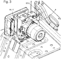
- Fig. 3
- das an der Halterung montierte Modul; und
- Fig. 4
- ein Detail der Halterung nach Abschluss der Montage.
-
Fig. 1 zeigt eine erfindungsgemäße Halterung 1, zusammengesetzt aus zwei Zuschnitten aus Stahlblech. Ein zentraler Bereich eines ersten der beiden Zuschnitte bildet eine Trägerplatte 3. An den Längsenden der Trägerplatte 3 ist jeweils ein Teil des ersten Zuschnitts in entgegengesetzte Richtungen gebogen, um eine Sicherungsplatte 4 und, entgegengesetzt zu dieser, einen Stützfuß 5 zu bilden. - Entlang eines Längsrandes der Trägerplatte 3 ist ein Steg 6 abgewinkelt. Der Steg 6 erstreckt sich vorbei an zwei Aufnahmen 7, 8 der Trägerplatte 3.
- Die Aufnahmen 7, 8 sind in die Trägerplatte 3 gestanzte Öffnungen. Jede Öffnung umfasst einen weiten Bereich 28 und einen engen Bereich 29, hier in Form von zwei sich geringfügig überschneiden, so dass die Breite eines Durchgangs zwischen den Bereichen 28, 29 etwas kleiner ist als der Durchmesser des engen Bereichs 29.
- Die Sicherungsplatte 4 weist eine weitere Aufnahme 9 an ihrem von der Trägerplatte 3 abgewandten Ende auf. Die Aufnahme 9 ist eine Öffnung, deren Durchmesser etwa dem des weiten Bereichs 28 entspricht, und die mit einem zum von der Trägerplatte 3 abgewandten Rand der Sicherungsplatte 4 hin über einen Durchgang 10 verbunden ist, der enger ist als die Aufnahme 9 selber.
- Die Aufnahmen 7-9 sind jeweils von einem umlaufenden Randsteg 11 begrenzt.
- Der zweite Zuschnitt ist zu einem Winkelstück 2 gebogen, von dem ein Schenkel 12 an der Sicherungsplatte 4 anliegend verschweißt ist und der andere eine zum Verschweißen an einer Unterlage im Fahrzeug vorgesehene Schweißlasche 13 bildet. Die Schweißlasche 13 und die Sicherungsplatte 4 erstrecken sich auf entgegengesetzten Seiten der Trägerplatte 3. Die Schweißlasche 13 liegt in einer Ebene, die im Wesentlichen parallel ist zu einer Ebene der Trägerplatte 3, so dass, wenn die Schweißlasche 13 auf einer ebenen Oberfläche 14 einer Unterlage befestigt ist, die Trägerplatte 3 sich in einem gleichbleibenden nichtverschwindenden Abstand von dieser erstreckt.
- Der Stützfuß 5 reicht über die Ebene der Schweißlasche 13 hinaus und kann seinerseits an einer gegen die ebene Oberfläche abgewinkelten Flanke 15 der Unterlage verschweißt sein.
-
Fig. 2 zeigt ein ESC-Modul 16 von an sich bekannter Bauart. Das Modul 16 hat ein starres Gehäuse 17, dessen Gestalt im Wesentlichen durch Komponenten im Innern und zu deren Versorgung und Steuerung benötigte Anschlüsse wie etwa einen Steckverbinder 18 und Ein- und Auslässe 19 für Bremsflüssigkeit bestimmt ist. Für die vorliegende Erfindung sind allerdings nur einzelne Oberflächen 20, 21 eines quaderförmigen Abschnitts des Gehäuses 17 von Bedeutung, von denen Vorsprünge 22, 23 abstehen. An der nach unten gewandten Oberfläche 20 sind zwei Vorsprünge 22 vorgesehen, an der seitlichen Oberfläche 19 ein Vorsprung 23. - Die Vorsprünge 22, 23 sind untereinander identisch. Sie können durch in das Gehäuse 17 eingeschraubte Stifte gebildet sein. Der Vorsprung 23 ist von einem elastischen Puffer 24 umgeben; formgleiche Puffer können an den Vorsprüngen 22 angebracht werden. Verdickte Enden der Vorsprünge 22, 23 bewirken eine Verrastung der Puffer 24 an den Vorsprüngen 22, 23.
- Die Puffer 24 sind Rotationskörper mit einer Längsachse, die auf der sie tragenden Oberfläche 20 bzw. 21 senkrecht steht. Sie umfassen jeweils zwei Kreisscheiben 25 von relativ großem Durchmesser, die voneinander in Richtung der Längsachse durch einen Abschnitt 26 von kleinerem Durchmesser und von der Oberfläche 20 bzw. 21 durch einen verdickten Abschnitt des sie tragenden Vorsprungs 22, 23 beabstandet sind.
- Die weiten Bereiche 28 der Aufnahmen 7, 8 sind bemessen, um, wenn der Puffer 24 von oben gegen die Trägerplatte 3 gedrückt wird, eine äußere der beiden Kreisscheiben 25 in elastisch verformtem Zustand soeben durchzulassen und anschließend dem Abschnitt 26 Platz zu bieten. Die Höhe des Randstegs 11 ist an die Länge des Abschnitts 26 angepasst, so dass gleichzeitig die äußere Kreisscheibe 25 an der Unterkante des Randstegs 11 und die innere Kreisscheibe 25 an der Oberseite der Trägerplatte 3 anliegen kann. Der Durchgang zum engen Bereich 29 ist etwas schmaler als der Durchmesser des Abschnitts 26, so dass der Puffer 24 unter Überwindung eines Widerstandes in den engen Bereich 29 verschoben werden kann und darin formschlüssig fixiert ist. Wenn in Puffer 24 in beiden Aufnahmen 7, 8 in dieser Weise platziert sind, entspricht der Abstand zwischen ihren inneren Durchgängen dem der Vorsprünge 22, so dass diese von oben in die Durchgänge eingeschoben werden können, ohne dass dabei die Puffer 24 aus den Aufnahmen 7, 8 herausgedrückt werden.
- Die Breite des Durchgangs 10 ist bemessen, um den Abschnitt 26 des auf den Vorsprung 23 aufgesteckten Puffers 24 von oben kommend durchzulassen und dabei quer zur Längsachse des Puffers 24 elastisch zu stauchen, so dass der Puffer 24 nach Passieren des Durchgangs 10 in der Öffnung 9 verrastet. Das Modul 16 kann somit ohne Werkzeug, durch einfaches Einrasten seiner Puffer 24 in den Aufnahmen 7, 8, 9, im Fahrzeug montiert werden.
- So wird die in
Fig. 3 gezeigte Konfiguration erreicht, in der das Modul 16 fest an der Halterung 1 gehalten ist. Von den zwei Kreisscheiben 25 der Puffer 24 in den Aufnahmen 7, 8 sitzt jeweils eine auf der Trägerplatte 3 und eine darunter, so dass das Gehäuse 17 mit der Trägerplatte 3 parallel gegenüberliegender und von ihr durch den verdickten Abschnitt der hier nicht sichtbaren Vorsprünge 22 und die innere Kreisscheibe 25 der Puffer 24 beabstandet gehaltener Oberfläche 20 fixiert ist. Der Puffer 24 am Vorsprung 23 ist in der Aufnahme 9 der Sicherungsplatte 4 verrastet. - Wie in
Fig. 1 gezeigt, sind in der Sicherungsplatte 4 beiderseits der Aufnahme 9 Löcher 30 gebildet. Diese sind vorgesehen, um daran einen Stecker 31 zu verrasten, der den Durchgang 10 versperrt und so ein Entweichen des ESP-Moduls aus der Halterung 1 sicher ausschließt. Fig. 10 zeigt das obere Ende der Sicherungsplatte 4 und den darauf aufgesteckten Stecker 31 teils in perspektivischer Ansicht, teils im Schnitt. Die Schnittebene verläuft durch eines der Löcher 30, um die Verbundung zwischen einem darin eingreifenden Widerhaken 32 und einer Grundplatte 33 des Steckers 31 zeigen zu können. Neben den beiden Widerhaken 32 stehen von der Grundplatte 33 zwei Paare von Klauen 34 nach unten ab, von denen eines in der Darstellung derFig. 4 weggeschnitten ist. Indem die Klauen 34 die Sicherungsplatte 4 beiderseits umgreifen, halten sie den Stecker 31 kippsicher auf deren oberer Kante. -
- 1
- Halterung
- 2
- Winkelstück
- 3
- Trägerplatte
- 4
- Sicherungsplatte
- 5
- Stützfuß
- 6
- Steg
- 7
- Öffnung
- 8
- Öffnung
- 9
- Öffnung
- 10
- Randöffnung
- 11
- Randsteg
- 12
- Schenkel
- 13
- Schweißlasche
- 14
- Oberfläche
- 15
- Flanke
- 16
- Modul
- 17
- Gehäuse
- 18
- Steckverbinder
- 19
- Ein- / Auslass
- 20
- Oberfläche
- 21
- Oberfläche
- 22
- Vorsprung
- 23
- Vorsprung
- 24
- zylindrischer Abschnitt
- 25
- Kreisscheibe
- 26
- Abschnitt von kleinerem Durchmesser
- 27
- Schaft
- 28
- weiter Bereich
- 29
- enger Bereich
- 30
- Loch
- 31
- Stecker
- 32
- Widerhaken
- 33
- Grundplatte
- 34
- Klaue
Claims (16)
Applications Claiming Priority (1)
| Application Number | Priority Date | Filing Date | Title |
|---|---|---|---|
| DE102021203611.2A DE102021203611A1 (de) | 2021-04-13 | 2021-04-13 | Halterung für ein ESC-Modul |
Publications (2)
| Publication Number | Publication Date |
|---|---|
| EP4074561A1 true EP4074561A1 (de) | 2022-10-19 |
| EP4074561B1 EP4074561B1 (de) | 2024-09-25 |
Family
ID=80999189
Family Applications (1)
| Application Number | Title | Priority Date | Filing Date |
|---|---|---|---|
| EP22161975.2A Active EP4074561B1 (de) | 2021-04-13 | 2022-03-14 | Halterung für ein esc-modul |
Country Status (2)
| Country | Link |
|---|---|
| EP (1) | EP4074561B1 (de) |
| DE (1) | DE102021203611A1 (de) |
Citations (3)
| Publication number | Priority date | Publication date | Assignee | Title |
|---|---|---|---|---|
| DE19963757A1 (de) * | 1999-12-30 | 2001-07-05 | Bosch Gmbh Robert | Elastische Lagerung eines insbesondere hydraulischen Aggregats einer Fahrzugbremsanlage |
| DE102006059923A1 (de) * | 2006-12-19 | 2008-06-26 | Robert Bosch Gmbh | Hydroaggregat einer hydraulischen Fahrzeugbremsanlage |
| DE102010042177A1 (de) | 2010-10-08 | 2012-04-12 | Robert Bosch Gmbh | Halteelement, Drehratenerfassungsmodul |
Family Cites Families (5)
| Publication number | Priority date | Publication date | Assignee | Title |
|---|---|---|---|---|
| FR2692338B1 (fr) | 1992-06-10 | 1994-09-02 | Salmson Pompes | Dispositif de montage de composant hydraulique tel qu'un corps de pompe et support pour un tel dispositif. |
| DE10036575A1 (de) | 2000-07-27 | 2002-02-07 | Bosch Gmbh Robert | Vorrichtung zur elastiscchen Lagerung eines hydraulischen Aggregats einer Fahrzeugbremsanlage in einem Fahrzeug |
| DE20019524U1 (de) | 2000-11-17 | 2001-03-29 | TRW Automotive Electronics & Components GmbH & Co. KG, 78315 Radolfzell | Gehäusesystem für sicherheitsrelevante Steuergeräte in Kraftfahrzeugen |
| DE10212145B4 (de) | 2002-03-19 | 2004-12-02 | J. Eberspächer GmbH & Co. KG | Befestigungsanordnung zur festen Anbringung eines Fahrzeugheizgerätes an einem Fahrzeug |
| DE102009018792A1 (de) | 2009-04-24 | 2009-11-05 | Daimler Ag | Halteelement |
-
2021
- 2021-04-13 DE DE102021203611.2A patent/DE102021203611A1/de active Pending
-
2022
- 2022-03-14 EP EP22161975.2A patent/EP4074561B1/de active Active
Patent Citations (3)
| Publication number | Priority date | Publication date | Assignee | Title |
|---|---|---|---|---|
| DE19963757A1 (de) * | 1999-12-30 | 2001-07-05 | Bosch Gmbh Robert | Elastische Lagerung eines insbesondere hydraulischen Aggregats einer Fahrzugbremsanlage |
| DE102006059923A1 (de) * | 2006-12-19 | 2008-06-26 | Robert Bosch Gmbh | Hydroaggregat einer hydraulischen Fahrzeugbremsanlage |
| DE102010042177A1 (de) | 2010-10-08 | 2012-04-12 | Robert Bosch Gmbh | Halteelement, Drehratenerfassungsmodul |
Also Published As
| Publication number | Publication date |
|---|---|
| DE102021203611A1 (de) | 2022-10-13 |
| EP4074561B1 (de) | 2024-09-25 |
Similar Documents
| Publication | Publication Date | Title |
|---|---|---|
| EP3602708B1 (de) | Anordnung aus einem schaltschrankrahmengestell und einem schaltschranksockel | |
| DE3617134C2 (de) | ||
| WO2007104463A1 (de) | Befestigungsanordnung | |
| DE19944685A1 (de) | Befestigungsanordnung zum Befestigen eines Verkleidungsteils an einem Kraftfahrzeug-Unterboden | |
| DE102011014424A1 (de) | Gehäuseanordnung mit einem Gehäuseteil für eine Regelungseinrichtung, insbesondere ein Steuergerät | |
| DE4123261C1 (de) | ||
| DE10210628C1 (de) | Vorrichtung zur spielfreien Ein-Mann Montage eines Anbauteils, oder einer Kfz-Dachantenne | |
| DE10348979B4 (de) | Befestigung einer Leiterplatte an einem Gehäuse | |
| DE20213362U1 (de) | Befestigungsanordnung für eine Heckleuchte | |
| EP4074561B1 (de) | Halterung für ein esc-modul | |
| DE4138047C2 (de) | Vorrichtung zum Verbinden mehrerer Teile | |
| DE19734601C2 (de) | Befestigungsvorrichtung | |
| DE102004024088B4 (de) | Spreizclipverbindung zweier Bauteile | |
| DE202005019612U1 (de) | Vorrichtung zur lösbaren Befestigung eines flachen Bauteils an einer Trägerstruktur | |
| DE10325435B4 (de) | Befestigung eines beifahrerseitigen Airbag-Moduls | |
| DE29616891U1 (de) | Einrichtung zum Befestigen eines Gassackmoduls | |
| DE102018107083A1 (de) | Befestigungseinrichtung und Verfahren zur Befestigung eines Anbauteils an einem Tragteil, Bauteilsystem und Kraftfahrzeug | |
| EP2237998A1 (de) | Getriebegehäuse einer wischeranlage mit einem steckpunkt als befestigungspunkt | |
| EP1105691B1 (de) | Wärmetauscher mit einem anschlusselement | |
| DE102021205869A1 (de) | Befestigungsvorrichtung, Dachantennenmodul und Verfahren | |
| WO2005071271A1 (de) | Fügeverband, sowie montagegruppe und trägerelement für den fügeverband und verfahren | |
| DE19963757A1 (de) | Elastische Lagerung eines insbesondere hydraulischen Aggregats einer Fahrzugbremsanlage | |
| DE102005044308A1 (de) | Montageanordnung | |
| DE102011109829A1 (de) | Befestigungsanordnung eines Gehäuses einer Fahrzeugkomponente an einem Fahrzeugbauteil und Gehäuse für eine Fahrzeugkomponente | |
| DE4431246C1 (de) | Klammerartige Befestigungsmutter |
Legal Events
| Date | Code | Title | Description |
|---|---|---|---|
| PUAI | Public reference made under article 153(3) epc to a published international application that has entered the european phase |
Free format text: ORIGINAL CODE: 0009012 |
|
| STAA | Information on the status of an ep patent application or granted ep patent |
Free format text: STATUS: THE APPLICATION HAS BEEN PUBLISHED |
|
| AK | Designated contracting states |
Kind code of ref document: A1 Designated state(s): AL AT BE BG CH CY CZ DE DK EE ES FI FR GB GR HR HU IE IS IT LI LT LU LV MC MK MT NL NO PL PT RO RS SE SI SK SM TR |
|
| STAA | Information on the status of an ep patent application or granted ep patent |
Free format text: STATUS: REQUEST FOR EXAMINATION WAS MADE |
|
| 17P | Request for examination filed |
Effective date: 20230324 |
|
| RBV | Designated contracting states (corrected) |
Designated state(s): AL AT BE BG CH CY CZ DE DK EE ES FI FR GB GR HR HU IE IS IT LI LT LU LV MC MK MT NL NO PL PT RO RS SE SI SK SM TR |
|
| RAP3 | Party data changed (applicant data changed or rights of an application transferred) |
Owner name: STELLANTIS AUTO SAS |
|
| RIC1 | Information provided on ipc code assigned before grant |
Ipc: B60T 8/36 20060101AFI20240503BHEP |
|
| GRAP | Despatch of communication of intention to grant a patent |
Free format text: ORIGINAL CODE: EPIDOSNIGR1 |
|
| STAA | Information on the status of an ep patent application or granted ep patent |
Free format text: STATUS: GRANT OF PATENT IS INTENDED |
|
| INTG | Intention to grant announced |
Effective date: 20240627 |
|
| GRAS | Grant fee paid |
Free format text: ORIGINAL CODE: EPIDOSNIGR3 |
|
| GRAA | (expected) grant |
Free format text: ORIGINAL CODE: 0009210 |
|
| STAA | Information on the status of an ep patent application or granted ep patent |
Free format text: STATUS: THE PATENT HAS BEEN GRANTED |
|
| AK | Designated contracting states |
Kind code of ref document: B1 Designated state(s): AL AT BE BG CH CY CZ DE DK EE ES FI FR GB GR HR HU IE IS IT LI LT LU LV MC MK MT NL NO PL PT RO RS SE SI SK SM TR |
|
| REG | Reference to a national code |
Ref country code: GB Ref legal event code: FG4D Free format text: NOT ENGLISH |
|
| REG | Reference to a national code |
Ref country code: CH Ref legal event code: EP |
|
| REG | Reference to a national code |
Ref country code: DE Ref legal event code: R096 Ref document number: 502022001725 Country of ref document: DE |
|
| REG | Reference to a national code |
Ref country code: DE Ref legal event code: R084 Ref document number: 502022001725 Country of ref document: DE Ref country code: IE Ref legal event code: FG4D Free format text: LANGUAGE OF EP DOCUMENT: GERMAN |
|
| REG | Reference to a national code |
Ref country code: LT Ref legal event code: MG9D |
|
| PG25 | Lapsed in a contracting state [announced via postgrant information from national office to epo] |
Ref country code: NO Free format text: LAPSE BECAUSE OF FAILURE TO SUBMIT A TRANSLATION OF THE DESCRIPTION OR TO PAY THE FEE WITHIN THE PRESCRIBED TIME-LIMIT Effective date: 20241225 |
|
| PG25 | Lapsed in a contracting state [announced via postgrant information from national office to epo] |
Ref country code: GR Free format text: LAPSE BECAUSE OF FAILURE TO SUBMIT A TRANSLATION OF THE DESCRIPTION OR TO PAY THE FEE WITHIN THE PRESCRIBED TIME-LIMIT Effective date: 20241226 Ref country code: FI Free format text: LAPSE BECAUSE OF FAILURE TO SUBMIT A TRANSLATION OF THE DESCRIPTION OR TO PAY THE FEE WITHIN THE PRESCRIBED TIME-LIMIT Effective date: 20240925 |
|
| PG25 | Lapsed in a contracting state [announced via postgrant information from national office to epo] |
Ref country code: BG Free format text: LAPSE BECAUSE OF FAILURE TO SUBMIT A TRANSLATION OF THE DESCRIPTION OR TO PAY THE FEE WITHIN THE PRESCRIBED TIME-LIMIT Effective date: 20240925 |
|
| PG25 | Lapsed in a contracting state [announced via postgrant information from national office to epo] |
Ref country code: LV Free format text: LAPSE BECAUSE OF FAILURE TO SUBMIT A TRANSLATION OF THE DESCRIPTION OR TO PAY THE FEE WITHIN THE PRESCRIBED TIME-LIMIT Effective date: 20240925 |
|
| PG25 | Lapsed in a contracting state [announced via postgrant information from national office to epo] |
Ref country code: RS Free format text: LAPSE BECAUSE OF FAILURE TO SUBMIT A TRANSLATION OF THE DESCRIPTION OR TO PAY THE FEE WITHIN THE PRESCRIBED TIME-LIMIT Effective date: 20241225 |
|
| REG | Reference to a national code |
Ref country code: NL Ref legal event code: MP Effective date: 20240925 |
|
| PG25 | Lapsed in a contracting state [announced via postgrant information from national office to epo] |
Ref country code: RS Free format text: LAPSE BECAUSE OF FAILURE TO SUBMIT A TRANSLATION OF THE DESCRIPTION OR TO PAY THE FEE WITHIN THE PRESCRIBED TIME-LIMIT Effective date: 20241225 Ref country code: NO Free format text: LAPSE BECAUSE OF FAILURE TO SUBMIT A TRANSLATION OF THE DESCRIPTION OR TO PAY THE FEE WITHIN THE PRESCRIBED TIME-LIMIT Effective date: 20241225 Ref country code: LV Free format text: LAPSE BECAUSE OF FAILURE TO SUBMIT A TRANSLATION OF THE DESCRIPTION OR TO PAY THE FEE WITHIN THE PRESCRIBED TIME-LIMIT Effective date: 20240925 Ref country code: GR Free format text: LAPSE BECAUSE OF FAILURE TO SUBMIT A TRANSLATION OF THE DESCRIPTION OR TO PAY THE FEE WITHIN THE PRESCRIBED TIME-LIMIT Effective date: 20241226 Ref country code: FI Free format text: LAPSE BECAUSE OF FAILURE TO SUBMIT A TRANSLATION OF THE DESCRIPTION OR TO PAY THE FEE WITHIN THE PRESCRIBED TIME-LIMIT Effective date: 20240925 Ref country code: BG Free format text: LAPSE BECAUSE OF FAILURE TO SUBMIT A TRANSLATION OF THE DESCRIPTION OR TO PAY THE FEE WITHIN THE PRESCRIBED TIME-LIMIT Effective date: 20240925 |
|
| PG25 | Lapsed in a contracting state [announced via postgrant information from national office to epo] |
Ref country code: NL Free format text: LAPSE BECAUSE OF FAILURE TO SUBMIT A TRANSLATION OF THE DESCRIPTION OR TO PAY THE FEE WITHIN THE PRESCRIBED TIME-LIMIT Effective date: 20240925 |
|
| PG25 | Lapsed in a contracting state [announced via postgrant information from national office to epo] |
Ref country code: IS Free format text: LAPSE BECAUSE OF FAILURE TO SUBMIT A TRANSLATION OF THE DESCRIPTION OR TO PAY THE FEE WITHIN THE PRESCRIBED TIME-LIMIT Effective date: 20250125 Ref country code: PT Free format text: LAPSE BECAUSE OF FAILURE TO SUBMIT A TRANSLATION OF THE DESCRIPTION OR TO PAY THE FEE WITHIN THE PRESCRIBED TIME-LIMIT Effective date: 20250127 |
|
| PG25 | Lapsed in a contracting state [announced via postgrant information from national office to epo] |
Ref country code: RO Free format text: LAPSE BECAUSE OF FAILURE TO SUBMIT A TRANSLATION OF THE DESCRIPTION OR TO PAY THE FEE WITHIN THE PRESCRIBED TIME-LIMIT Effective date: 20240925 Ref country code: SM Free format text: LAPSE BECAUSE OF FAILURE TO SUBMIT A TRANSLATION OF THE DESCRIPTION OR TO PAY THE FEE WITHIN THE PRESCRIBED TIME-LIMIT Effective date: 20240925 |
|
| PG25 | Lapsed in a contracting state [announced via postgrant information from national office to epo] |
Ref country code: ES Free format text: LAPSE BECAUSE OF FAILURE TO SUBMIT A TRANSLATION OF THE DESCRIPTION OR TO PAY THE FEE WITHIN THE PRESCRIBED TIME-LIMIT Effective date: 20240925 |
|
| PG25 | Lapsed in a contracting state [announced via postgrant information from national office to epo] |
Ref country code: EE Free format text: LAPSE BECAUSE OF FAILURE TO SUBMIT A TRANSLATION OF THE DESCRIPTION OR TO PAY THE FEE WITHIN THE PRESCRIBED TIME-LIMIT Effective date: 20240925 |
|
| PG25 | Lapsed in a contracting state [announced via postgrant information from national office to epo] |
Ref country code: PL Free format text: LAPSE BECAUSE OF FAILURE TO SUBMIT A TRANSLATION OF THE DESCRIPTION OR TO PAY THE FEE WITHIN THE PRESCRIBED TIME-LIMIT Effective date: 20240925 Ref country code: CZ Free format text: LAPSE BECAUSE OF FAILURE TO SUBMIT A TRANSLATION OF THE DESCRIPTION OR TO PAY THE FEE WITHIN THE PRESCRIBED TIME-LIMIT Effective date: 20240925 |
|
| PG25 | Lapsed in a contracting state [announced via postgrant information from national office to epo] |
Ref country code: IT Free format text: LAPSE BECAUSE OF FAILURE TO SUBMIT A TRANSLATION OF THE DESCRIPTION OR TO PAY THE FEE WITHIN THE PRESCRIBED TIME-LIMIT Effective date: 20240925 Ref country code: SK Free format text: LAPSE BECAUSE OF FAILURE TO SUBMIT A TRANSLATION OF THE DESCRIPTION OR TO PAY THE FEE WITHIN THE PRESCRIBED TIME-LIMIT Effective date: 20240925 |
|
| REG | Reference to a national code |
Ref country code: DE Ref legal event code: R097 Ref document number: 502022001725 Country of ref document: DE |
|
| PG25 | Lapsed in a contracting state [announced via postgrant information from national office to epo] |
Ref country code: DK Free format text: LAPSE BECAUSE OF FAILURE TO SUBMIT A TRANSLATION OF THE DESCRIPTION OR TO PAY THE FEE WITHIN THE PRESCRIBED TIME-LIMIT Effective date: 20240925 |
|
| PLBE | No opposition filed within time limit |
Free format text: ORIGINAL CODE: 0009261 |
|
| STAA | Information on the status of an ep patent application or granted ep patent |
Free format text: STATUS: NO OPPOSITION FILED WITHIN TIME LIMIT |
|
| 26N | No opposition filed |
Effective date: 20250626 |
|
| PG25 | Lapsed in a contracting state [announced via postgrant information from national office to epo] |
Ref country code: SE Free format text: LAPSE BECAUSE OF FAILURE TO SUBMIT A TRANSLATION OF THE DESCRIPTION OR TO PAY THE FEE WITHIN THE PRESCRIBED TIME-LIMIT Effective date: 20240925 |
|
| PG25 | Lapsed in a contracting state [announced via postgrant information from national office to epo] |
Ref country code: MC Free format text: LAPSE BECAUSE OF FAILURE TO SUBMIT A TRANSLATION OF THE DESCRIPTION OR TO PAY THE FEE WITHIN THE PRESCRIBED TIME-LIMIT Effective date: 20240925 |
|
| REG | Reference to a national code |
Ref country code: CH Ref legal event code: H13 Free format text: ST27 STATUS EVENT CODE: U-0-0-H10-H13 (AS PROVIDED BY THE NATIONAL OFFICE) Effective date: 20251023 |
|
| PG25 | Lapsed in a contracting state [announced via postgrant information from national office to epo] |
Ref country code: LU Free format text: LAPSE BECAUSE OF NON-PAYMENT OF DUE FEES Effective date: 20250314 |
|
| REG | Reference to a national code |
Ref country code: BE Ref legal event code: MM Effective date: 20250331 |
|
| PG25 | Lapsed in a contracting state [announced via postgrant information from national office to epo] |
Ref country code: HR Free format text: LAPSE BECAUSE OF FAILURE TO SUBMIT A TRANSLATION OF THE DESCRIPTION OR TO PAY THE FEE WITHIN THE PRESCRIBED TIME-LIMIT Effective date: 20240925 |
|
| PG25 | Lapsed in a contracting state [announced via postgrant information from national office to epo] |
Ref country code: BE Free format text: LAPSE BECAUSE OF NON-PAYMENT OF DUE FEES Effective date: 20250331 |
|
| PG25 | Lapsed in a contracting state [announced via postgrant information from national office to epo] |
Ref country code: CH Free format text: LAPSE BECAUSE OF NON-PAYMENT OF DUE FEES Effective date: 20250331 |
|
| PG25 | Lapsed in a contracting state [announced via postgrant information from national office to epo] |
Ref country code: IE Free format text: LAPSE BECAUSE OF NON-PAYMENT OF DUE FEES Effective date: 20250314 |
|
| PGFP | Annual fee paid to national office [announced via postgrant information from national office to epo] |
Ref country code: DE Payment date: 20260219 Year of fee payment: 5 |
|
| PGFP | Annual fee paid to national office [announced via postgrant information from national office to epo] |
Ref country code: AT Payment date: 20260301 Year of fee payment: 5 |
|
| PGFP | Annual fee paid to national office [announced via postgrant information from national office to epo] |
Ref country code: FR Payment date: 20260219 Year of fee payment: 5 |