EP4074387B1 - Sammelsystem für verstreute objekte und sammelverfahren für verstreute objekte - Google Patents
Sammelsystem für verstreute objekte und sammelverfahren für verstreute objekte Download PDFInfo
- Publication number
- EP4074387B1 EP4074387B1 EP21751227.6A EP21751227A EP4074387B1 EP 4074387 B1 EP4074387 B1 EP 4074387B1 EP 21751227 A EP21751227 A EP 21751227A EP 4074387 B1 EP4074387 B1 EP 4074387B1
- Authority
- EP
- European Patent Office
- Prior art keywords
- dispersed
- working area
- objects
- collection
- machine
- Prior art date
- Legal status (The legal status is an assumption and is not a legal conclusion. Google has not performed a legal analysis and makes no representation as to the accuracy of the status listed.)
- Active
Links
Images



Classifications
-
- A—HUMAN NECESSITIES
- A63—SPORTS; GAMES; AMUSEMENTS
- A63B—APPARATUS FOR PHYSICAL TRAINING, GYMNASTICS, SWIMMING, CLIMBING, OR FENCING; BALL GAMES; TRAINING EQUIPMENT
- A63B47/00—Devices for handling or treating balls, e.g. for holding or carrying balls
- A63B47/02—Devices for handling or treating balls, e.g. for holding or carrying balls for picking-up or collecting
- A63B47/021—Devices for handling or treating balls, e.g. for holding or carrying balls for picking-up or collecting for picking-up automatically, e.g. by apparatus moving over the playing surface
-
- G—PHYSICS
- G05—CONTROLLING; REGULATING
- G05D—SYSTEMS FOR CONTROLLING OR REGULATING NON-ELECTRIC VARIABLES
- G05D1/00—Control of position, course, altitude or attitude of land, water, air or space vehicles, e.g. using automatic pilots
- G05D1/02—Control of position or course in two dimensions
- G05D1/021—Control of position or course in two dimensions specially adapted to land vehicles
- G05D1/0268—Control of position or course in two dimensions specially adapted to land vehicles using internal positioning means
- G05D1/0274—Control of position or course in two dimensions specially adapted to land vehicles using internal positioning means using mapping information stored in a memory device
-
- G—PHYSICS
- G05—CONTROLLING; REGULATING
- G05D—SYSTEMS FOR CONTROLLING OR REGULATING NON-ELECTRIC VARIABLES
- G05D1/00—Control of position, course, altitude or attitude of land, water, air or space vehicles, e.g. using automatic pilots
- G05D1/02—Control of position or course in two dimensions
- G05D1/021—Control of position or course in two dimensions specially adapted to land vehicles
- G05D1/0212—Control of position or course in two dimensions specially adapted to land vehicles with means for defining a desired trajectory
- G05D1/0217—Control of position or course in two dimensions specially adapted to land vehicles with means for defining a desired trajectory in accordance with energy consumption, time reduction or distance reduction criteria
-
- G—PHYSICS
- G05—CONTROLLING; REGULATING
- G05D—SYSTEMS FOR CONTROLLING OR REGULATING NON-ELECTRIC VARIABLES
- G05D1/00—Control of position, course, altitude or attitude of land, water, air or space vehicles, e.g. using automatic pilots
- G05D1/02—Control of position or course in two dimensions
- G05D1/021—Control of position or course in two dimensions specially adapted to land vehicles
- G05D1/0212—Control of position or course in two dimensions specially adapted to land vehicles with means for defining a desired trajectory
- G05D1/0219—Control of position or course in two dimensions specially adapted to land vehicles with means for defining a desired trajectory ensuring the processing of the whole working surface
-
- G—PHYSICS
- G05—CONTROLLING; REGULATING
- G05D—SYSTEMS FOR CONTROLLING OR REGULATING NON-ELECTRIC VARIABLES
- G05D1/00—Control of position, course, altitude or attitude of land, water, air or space vehicles, e.g. using automatic pilots
- G05D1/02—Control of position or course in two dimensions
- G05D1/021—Control of position or course in two dimensions specially adapted to land vehicles
- G05D1/0276—Control of position or course in two dimensions specially adapted to land vehicles using signals provided by a source external to the vehicle
- G05D1/028—Control of position or course in two dimensions specially adapted to land vehicles using signals provided by a source external to the vehicle using a RF signal
- G05D1/0282—Control of position or course in two dimensions specially adapted to land vehicles using signals provided by a source external to the vehicle using a RF signal generated in a local control room
-
- G—PHYSICS
- G06—COMPUTING OR CALCULATING; COUNTING
- G06V—IMAGE OR VIDEO RECOGNITION OR UNDERSTANDING
- G06V20/00—Scenes; Scene-specific elements
- G06V20/50—Context or environment of the image
-
- G—PHYSICS
- G06—COMPUTING OR CALCULATING; COUNTING
- G06V—IMAGE OR VIDEO RECOGNITION OR UNDERSTANDING
- G06V20/00—Scenes; Scene-specific elements
- G06V20/50—Context or environment of the image
- G06V20/52—Surveillance or monitoring of activities, e.g. for recognising suspicious objects
-
- A—HUMAN NECESSITIES
- A63—SPORTS; GAMES; AMUSEMENTS
- A63B—APPARATUS FOR PHYSICAL TRAINING, GYMNASTICS, SWIMMING, CLIMBING, OR FENCING; BALL GAMES; TRAINING EQUIPMENT
- A63B47/00—Devices for handling or treating balls, e.g. for holding or carrying balls
- A63B47/02—Devices for handling or treating balls, e.g. for holding or carrying balls for picking-up or collecting
- A63B47/021—Devices for handling or treating balls, e.g. for holding or carrying balls for picking-up or collecting for picking-up automatically, e.g. by apparatus moving over the playing surface
- A63B2047/022—Autonomous machines which find their own way around the playing surface
-
- A—HUMAN NECESSITIES
- A63—SPORTS; GAMES; AMUSEMENTS
- A63B—APPARATUS FOR PHYSICAL TRAINING, GYMNASTICS, SWIMMING, CLIMBING, OR FENCING; BALL GAMES; TRAINING EQUIPMENT
- A63B2102/00—Application of clubs, bats, rackets or the like to the sporting activity ; particular sports involving the use of balls and clubs, bats, rackets, or the like
- A63B2102/32—Golf
-
- A—HUMAN NECESSITIES
- A63—SPORTS; GAMES; AMUSEMENTS
- A63B—APPARATUS FOR PHYSICAL TRAINING, GYMNASTICS, SWIMMING, CLIMBING, OR FENCING; BALL GAMES; TRAINING EQUIPMENT
- A63B2220/00—Measuring of physical parameters relating to sporting activity
- A63B2220/05—Image processing for measuring physical parameters
-
- A—HUMAN NECESSITIES
- A63—SPORTS; GAMES; AMUSEMENTS
- A63B—APPARATUS FOR PHYSICAL TRAINING, GYMNASTICS, SWIMMING, CLIMBING, OR FENCING; BALL GAMES; TRAINING EQUIPMENT
- A63B2220/00—Measuring of physical parameters relating to sporting activity
- A63B2220/17—Counting, e.g. counting periodical movements, revolutions or cycles, or including further data processing to determine distances or speed
-
- A—HUMAN NECESSITIES
- A63—SPORTS; GAMES; AMUSEMENTS
- A63B—APPARATUS FOR PHYSICAL TRAINING, GYMNASTICS, SWIMMING, CLIMBING, OR FENCING; BALL GAMES; TRAINING EQUIPMENT
- A63B2220/00—Measuring of physical parameters relating to sporting activity
- A63B2220/80—Special sensors, transducers or devices therefor
- A63B2220/807—Photo cameras
-
- A—HUMAN NECESSITIES
- A63—SPORTS; GAMES; AMUSEMENTS
- A63B—APPARATUS FOR PHYSICAL TRAINING, GYMNASTICS, SWIMMING, CLIMBING, OR FENCING; BALL GAMES; TRAINING EQUIPMENT
- A63B2220/00—Measuring of physical parameters relating to sporting activity
- A63B2220/80—Special sensors, transducers or devices therefor
- A63B2220/83—Special sensors, transducers or devices therefor characterised by the position of the sensor
- A63B2220/833—Sensors arranged on the exercise apparatus or sports implement
-
- A—HUMAN NECESSITIES
- A63—SPORTS; GAMES; AMUSEMENTS
- A63B—APPARATUS FOR PHYSICAL TRAINING, GYMNASTICS, SWIMMING, CLIMBING, OR FENCING; BALL GAMES; TRAINING EQUIPMENT
- A63B69/00—Training appliances or apparatus for special sports
- A63B69/36—Training appliances or apparatus for special sports for golf
- A63B69/3691—Golf practising terrains
- A63B69/3694—Golf practising terrains for driving only
-
- G—PHYSICS
- G01—MEASURING; TESTING
- G01S—RADIO DIRECTION-FINDING; RADIO NAVIGATION; DETERMINING DISTANCE OR VELOCITY BY USE OF RADIO WAVES; LOCATING OR PRESENCE-DETECTING BY USE OF THE REFLECTION OR RERADIATION OF RADIO WAVES; ANALOGOUS ARRANGEMENTS USING OTHER WAVES
- G01S5/00—Position-fixing by co-ordinating two or more direction or position line determinations; Position-fixing by co-ordinating two or more distance determinations
- G01S5/16—Position-fixing by co-ordinating two or more direction or position line determinations; Position-fixing by co-ordinating two or more distance determinations using electromagnetic waves other than radio waves
Definitions
- the present invention relates to a dispersed object collection system configured to collect dispersed objects in a working area while running by itself, and a dispersed object collection method.
- An example of dispersed objects includes balls hit and scattered in a golf practice range.
- a self-running ball collection system including a memory configured to store information about ball distribution in a working area, and a processor configured to guide a vehicle into the working area based on the information stored in the memory and collect the balls (see Japanese Patent Application Laid-Open No. 2008-220935 ).
- US 2010/250024 A1 describes a motorised system with electric traction with computer vision for outdoor environments, which can interact with the surrounding environment in an autonomous way or remotely operated.
- the vehicle tows a trailer that permits, amongst other functions, to perform golf balls picking.
- This prior art document discloses a dispersed object collection system and a dispersed object collection method according to the respective preamble of independent claims 1 and 8.
- KR 2010 0094909 A discloses a golf ball picking system comprising a robot which is navigated within a golf range and which efficiently collects golf balls in that the golf ball distribution on the green is considered.
- US 2020/019752 A1 discloses a further collecting system comprising a machine which is navigated within a field so as to efficiently collect dispersed objects such as, e.g., golf balls.
- KR 101 430103 B1 discloses another golf ball picking system comprising a robot which is efficiently navigated on the basis of the golf ball distribution.
- the self-running collection systems according to the conventional art have a problem to improve the efficiency of the running of the vehicle to collect more dispersed objects for a short time.
- the conventional art proposes to run the vehicle based on the information about the distribution of the dispersed objects in the working area, and describes that a location where balls are or may be more highly distributed or more gathered than other locations is designated as the working area to be prioritized.
- the conventional art vaguely describes that it is based on predicted distribution of dispersed objects, or based on monitoring of dispersed condition by a vision sensor, but does not describe a concrete method of setting the working area to reduce the running of the vehicle not performing the collection work as much as possible.
- the collection system is electrically operated to run the vehicle and perform the work
- the efficiency of the work is significantly down. Therefore, in order to perform efficient collection work, it is important for the electric collection system to reduce the consumption of the battery as much as possible to reduce the number of times to charge the battery (or avoid charging the battery) during the work.
- the above-described conventional art does not describe the setting of the working area in view of the battery consumption, and therefore has the problem that it is not possible to effectively promote the efficiency of the work when being applied to the electric collection system.
- the present invention is proposed to address the above-described problem. It is therefore an object of the invention to present specific measures to improve the efficiency of the collection work of a self-running dispersed object collection system, by reducing the running of a machine not performing the collection work to collect dispersed objects as much as possible, and to effectively promote the efficiency of the work by setting a working area in view of the battery consumption of the electric collection system.
- the invention provides a dispersed object collection system according to claim 1.
- the invention relates to a dispersed object collection method according to claim 8.
- the dispersed object collection system having the above-described feature, it is possible to improve the efficiency of the collection work of the self-running dispersed object collection system by reducing the running of a machine not performing the collection work to collect dispersed objects as much as possible, and effectively promote the efficiency of the work by setting the working area in view of the battery consumption of the electric collection system.
- the dispersed object collection system is configured to appropriately set an activity area Fa in a facility zone Fs as illustrated in Fig. 1 , and collect dispersed objects P dispersed in the activity area Fa by causing a machine 10 to run by itself in the activity area Fa.
- a collection place Ga is provided outside the activity area Fa in the facility zone Fs.
- the machine 10 starts from the collection place Ga or another start point, and accommodates the dispersed objects P into an accommodation section 11 provided in or outside the machine 10 in the course of running by itself in the activity area Fa.
- the machine 10 After the end of predetermined collection work, the machine 10 returns to the collection place Ga, and discharges the dispersed objects P accommodated in the accommodation section 11 to the collection place Ga.
- the collection place Ga is provided with charging equipment Es.
- the machine 10 is electrically operated, and when the machine 10 returns to the collection place Ga, a battery 12 of the machine 10 is charged by the charging equipment Es.
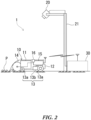
- FIG. 2 illustrates the equipment configuration of the dispersed object collection system.
- a dispersed object collection system 1 includes a machine 10 configured to run by itself in the above-described activity area Fa; a camera 20 configured to look down at part or the whole of the activity area Fa to capture an image of part or the whole of the activity area Fa; and a work instruction transmitter 30 configured to acquire the image captured by the camera 20 and transmit a work instruction to the machine 10.
- the machine 10 includes, in addition to the above-described accommodation section 11 and the battery 12, a running part 13 (running wheels 13a and running drive part 13b) configured to run on a field surface of the activity area Fa; a pickup mechanism 14 configure to pick up the dispersed objects P from the field surface and put the dispersed objects P into the accommodation section 11; and a controller 15 configured to control the running part 13 and the pickup mechanism 14 based on an instruction signal received from the work instruction transmitter 30, and a detection signal from a position detector 16 such as a GPS receiver.
- a position detector 16 such as a GPS receiver
- the camera 20 transmits the captured image of part or the whole of the activity area Fa to the work instruction transmitter 30 as needed, regularly, or according to the instruction from a user, depending on the working situation of the dispersed object collection system 1.
- the camera 20 can capture an image of a predetermined range of the activity area Fa according to a control signal from the work instruction transmitter 30.
- the work instruction transmitter 30 can recognize positional information of the capturing range (angle of view) of the camera 20.
- the camera 20 is supported by a predetermined support (a pillar, or a wall surface or a ceiling surface of the facility) 21 in order to look down at the activity area Fa to capture the image of the activity area Fa.
- a predetermined support a pillar, or a wall surface or a ceiling surface of the facility
- the camera 20 may be installed in the machine 10.
- the camera 20 provided in the facility and the camera 20 provided in the machine 10 may be used together.
- the work instruction transmitter 30 sets the working area in the activity area Fa; sets a running route through which the machine 10 having started from the collection place Ga (or another place) performs the collection work in the set working area and returns to the collection place Ga; and transmits data of the setting to the machine 10.
- the work instruction transmitter 30 is provided outside the machine 10, but the controller 15 of the machine 10 may have the function the same as the work instruction transmitter 30.
- image information acquired by the camera 20 is transmitted to the controller 15, or image information acquired by an outside camera is previously inputted to the controller 15.
- the controller 15 sets the working area and the running route by itself.
- Fig. 3 schematically illustrates an operation process of the work instruction transmitter 30.
- a first step (image acquisition step) S1 an image is acquired from the camera 20 to set the working area.
- the acquired image is an image of the field in the activity area Fa in which dispersed objects are dispersed, and a still image of the set capturing range and positional information of the capturing range are acquired at the same time.
- a second step (working area setting step) S2 the working area is set based on the acquired image.
- Image processing is applied to the acquired image to distinguish between the image of dispersed objects (such as balls) and the other images (such as the background image).
- the positions of the dispersed objects P existing in the acquired image are recognized on a position coordinate (X-Y coordinate) corresponding to the capturing range of the acquired image.
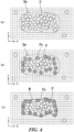
- an aggregation region Se in which a plurality of dispersed objects are close together is specified as illustrated in Fig. 4(a) .
- the aggregation region Se for example, the position coordinate and the image of the dispersed objects P are displayed on a display screen, a line surrounding the aggregation of the dispersed objects P being close together is inputted by using a predetermined input tool (such as a touch pad, a touch pen, a mouse, and a keyboard), and a closed region surrounded by the line is specified as the aggregation region Se.
- a predetermined input tool such as a touch pad, a touch pen, a mouse, and a keyboard
- the aggregation region Se may be set directly as the working area. Moreover, in order to improve the efficiency of the collection work by narrowing down the working area, and reducing the running of the machine 10 not performing the collection work to collect the dispersed objects as much as possible, the working area is set according to the following process.
- the dispersed objects P in the aggregation region Se is specified, and among them, outermost dispersed objects Ps are further specified as illustrated in Fig. 4(b) .
- Each of the outermost dispersed objects Ps can be specified as a dispersed object P which has no dispersed object P outside it in one of the X direction and the Y direction, which is determined based on the X-Y coordinate position of each of the dispersed objects P in the aggregation region Se. Whether there is a dispersed object P outside it is determined by determining whether there is a dispersed object P outside it within the width (diameter) of the dispersed object P.
- a closed region along the outer edge of each of the outermost dispersed objects Ps is set as illustrated in Fig. 4(c) , and this closed region is set as a working area W. In this way, by setting the working area W, it is possible to reduce the running of the machine 10 not performing the collection work to collect the dispersed objects P as much as possible, and therefore to improve the efficiency of the collection work.
- the closed region is set to contact the outer edges of the outermost dispersed objects Ps, but may be set to be a little apart from the outer edges of the outermost dispersed objects Ps, or may be set to connect parts such as the centers of the outermost dispersed objects Ps to each other.
- the aggregation region Se is specified by hand using the input tool.
- the aggregation region Se is specified by arithmetic processing.
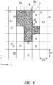
- a unit region having width X1 in the X direction and width Y1 in the Y direction is set for the position of each of the dispersed objects P on the above-described position coordinate, and the number of the dispersed objects P in each of the unit regions is counted.
- the unit regions each having the number of dispersed objects equal to or greater than a set value are connected to form the aggregation region Se.
- the set value is equal to or greater than five, and the unit regions with cross-hatching form the aggregation region Se.
- the aggregation region Se with cross-hatching specified as described above can be set directly as the working area W. Meanwhile, as described above, the outermost dispersed objects Ps in the aggregation region Se are specified, and the closed region along the outer edges of the outermost dispersed objects Ps may be set as the working area W as illustrated in Fig. 5 .
- a method to specify the aggregation region Se by the arithmetic processing is not limited to the above-described example.
- the positions of the dispersed objects P dispersed on the position coordinate are specified, and an aggregation of the dispersed objects in which the distance between two adjacent dispersed objects is equal to or smaller than a predetermined value is specified and may be set as the aggregation region Se.
- the number of the dispersed objects P in the working area W is set to be smaller than the capacity of the accommodation section 11 of the machine 10.
- the machine 10 is returned to the collection place Ga once to discharge the dispersed objects P, and collects the dispersed objects P in the working area W again, and therefore it is not possible to perform efficient collection work.
- the working area W is set to allow the efficient correction work by performing the work once.
- the size and the location of the aggregation region Se are set to achieve the optimal efficiency, under the conditions such as the traveling distance of the machine 10 and the battery consumption.
- the working area W is set in the second step (working area setting step) S2, and next, the running route of the machine 10 is set in the third step (running route setting step) S3.
- a running route R is formed by making turns of a straight line along the longitudinal direction of the working area W as illustrated in Fig. 6 . In this way, for the running in the entire working area W, it is possible to reduce the number of turns, and therefore to improve the efficiency of the collection work.
- the running route is set to shorten the running distance.
- the running route is set such that the running distance of the machine 10 from the working area W to the collection place Ga is minimized.
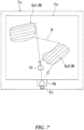
- a point B at which the machine 10 enters the working area W is set to be far from the collection place Ga so that a point A at which the machine 10 leaves the working area W is close to the collection place Ga.
- the running route of the machine 10 is set such that the work is performed first on the working area W in the aggregation region Se2 which is the most far from the collection place Ga, and the work is performed last on the working area W in the aggregation region Se1 which is the closest to the collection place Ga.
- any of them may be selected to set the working area W.
- the aggregation region Se with a high work efficiency is selected based on the distance from the collection place Ga to the aggregation region Se and the number of the dispersed objects in the aggregation region Se, and the working area W is set in the selected aggregation region Se.
- the priority of the plurality of aggregation regions Se is determined, based on the distance from the collection place Ga to the aggregation regions Se and the number of the dispersed objects in the aggregation regions Se, and the collection work may be performed first on the working area W in the aggregation region Se with a high priority.
- the running speed of the machine 10 on the running route may be appropriately set as follows: in view of the collection rate, the running speed is reduced in the working area W; in view of the battery consumption and the working time, the running speed of the machine 10 having the empty accommodation section 11 is increased; and the running speed is reduced when the occupancy rate of the accommodation section 11 is high.
- data of the set working area W and data of the set running route are transmitted from the work instruction transmitter 30 to the controller 15 of the machine 10 in a fourth step (data transmission step) S4 as illustrated in Fig. 3 .
- the controller 15 of the machine 10 controls each of the parts of the machine 10 according to the data transmitted from the work instruction transmitter 30, and performs the collection work to collect the dispersed objects P in the set working area W while causing the machine 10 to run by itself.
- step S5: NO the collection work to collect the dispersed objects P in the working area W is continued until it is determined that the work is ended
- step S5: YES the controller 15 transmits a signal to inform the end to the work instruction transmitter 30.
- the work instruction transmitter 30 determines whether to set the next working area W, and when it is determined to set the next working area W (step S6: YES), the step is returned to the step S1, and the step S1 to the step S5 are performed.
- step S6: NO the process is ended.
- the setting of the working area W in the step S1 may be performed at an appropriate timing.
- the setting may be performed regularly at a prescribed interval or time, or may be performed optionally by designation of a user.
- the setting may be performed at the timing when the machine 10 returns to the collection place Ga.
- the dispersed object collection system 1 can properly set the working area W to reduce the running of the machine 10 not performing the collection work to collect the dispersed objects as much as possible, and therefore can improve the efficiency of the collection work. In addition, it is possible to effectively promote the efficiency of the work by setting the working area W and the running route in view of the battery consumption.
- the dispersed object collection system 1 can be installed in a facility such as a golf practice range, and can be used to collect balls hit from bays. In this case, even though the bays are occupied, it is possible to perform the collection work to collect balls, and perform efficient collection work. Therefore, it is possible to shorten the period of time until the balls hit from the bays are collected. By this means, it is possible to reduce the stock quantity of the balls in the facility, and consequently to smoothly and economically manage the facility.
- the dispersed object collection system 1 is not limited to the system for the collection work to collect balls.
- the dispersed object collection system 1 is applicable to the collection work to collect various kinds of dispersed objects such as harvested crops and grass on an agricultural field, and can perform efficient collection work.
Landscapes
- Engineering & Computer Science (AREA)
- General Physics & Mathematics (AREA)
- Physics & Mathematics (AREA)
- Radar, Positioning & Navigation (AREA)
- Aviation & Aerospace Engineering (AREA)
- Automation & Control Theory (AREA)
- Remote Sensing (AREA)
- Multimedia (AREA)
- Theoretical Computer Science (AREA)
- Physical Education & Sports Medicine (AREA)
- General Health & Medical Sciences (AREA)
- Health & Medical Sciences (AREA)
- Control Of Position, Course, Altitude, Or Attitude Of Moving Bodies (AREA)
Claims (10)
- Sammelsystem (1) für verstreute Objekte, umfassend eine elektrische Maschine (10), die konfiguriert ist, um:von selbst entlang einer festgelegten Laufroute (R) in einem Aktivitätsbereich (Fa) zu laufen,von einem Sammelplatz (Ga) aus zu beginnen,von selbst in einem festgelegten Arbeitsbereich (W) zu laufen, um verstreute Objekte (P), die in dem Arbeitsbereich (W) verstreut sind, in einen Aufnahmeabschnitt (11) aufzunehmen, der in oder außerhalb der Maschine (10) bereitgestellt ist, unddie verstreuten Objekte (P) an dem Sammelplatz (Ga) zu sammeln,wobei das Sammelsystem (1) für verstreute Objekte ferner umfasst:dadurch gekennzeichnet, dass der Arbeitsanweisungssender (30) ferner konfiguriert ist, umeine Kamera (20), die konfiguriert ist, um auf den Aktivitätsbereich (Fa) herunterzuschauen, um ein Bild des Aktivitätsbereichs (Fa) aufzunehmen, undeinen Arbeitsanweisungssender (30), der konfiguriert ist, um den Arbeitsbereich (W) in dem Aktivitätsbereich (Fa) festzulegen und eine Laufroute (R) festzulegen, durch die die Maschine (10), die von dem Sammelplatz (Ga) aus gestartet ist, die Sammelarbeit in dem festgelegten Arbeitsbereich (W) durchführt und zu dem Sammelplatz (Ga) zurückkehrt,wobei der Arbeitsanweisungssender (30) ferner konfiguriert ist, um:ein Bild des Feldes in dem Aktivitätsbereich (Fa), in dem verstreute Objekte (P) verstreut sind, von der Kamera (20) zu erhalten,die Positionen der verstreuten Objekte (P), die in dem erhaltenen Bild vorhanden sind, auf einer Positionskoordinate (X-Y-Koordinate) zu erkennen, die dem Aufnahmebereich des erhaltenen Bildes entspricht,einen Aggregationsbereich (Se; Se1, Se2) durch Verbinden von Einheitsbereichen zu bilden, wobei jeder der Einheitsbereiche die Anzahl von verstreuten Objekten (P) aufweist, die gleich oder größer als ein festgelegter Wert ist, oder alternativ den Aggregationsbereich (Se; Se1, Se2) derart festzulegen, dass ein Abstand zwischen zwei benachbarten verstreuten Objekten (P) gleich oder kleiner als ein festgelegter Wert ist, undden Arbeitsbereich (W) als einen geschlossenen Bereich entlang äußerer Kanten der verstreuten Objekte (P) in dem Aggregationsbereich festzulegen, in dem eine Vielzahl von verstreuten Objekten (P) nahe beieinander sind.
- Sammelsystem (1) für verstreute Objekte nach Anspruch 1, wobei der Arbeitsbereich (W) derart festgelegt ist, dass die Anzahl von verstreuten Objekten (P) in dem Arbeitsbereich (W) kleiner als die Kapazität des Aufnahmeabschnitts (11) ist.
- Sammelsystem (1) für verstreute Objekte nach einem der Ansprüche 1 bis 2, wobei die Laufroute (R) der Maschine (10) in dem Arbeitsbereich (W) durch Hin- und Herfahrten entlang einer Längsrichtung des Arbeitsbereichs (W) gebildet wird.
- Sammelsystem (1) für verstreute Objekte nach einem der Ansprüche 1 bis 3, wobei der Sammelplatz (Ga) mit Ladeausrüstung (Es) versehen ist, die konfiguriert ist, um einen Akkumulator (12) der Maschine (10) zu laden.
- Sammelsystem (1) für verstreute Objekte nach Anspruch 4, wobei die Laufroute (R) der Maschine (10) derart festgelegt ist, dass ein Laufabstand der Maschine (10) von dem Arbeitsbereich (W) zu dem Sammelplatz (Ga) minimiert ist.
- Sammelsystem (1) für verstreute Objekte nach Anspruch 4, wobei:der Arbeitsbereich (W) derart festgelegt ist, dass er durch eine Vielzahl von Aggregationsbereichen (Se1, Se2) gebildet wird, die voneinander beabstandet sind; unddie Laufroute (R) der Maschine (10) derart festgelegt ist, dass zuerst an dem Arbeitsbereich (W), der am weitesten von dem Sammelplatz (Ga) entfernt ist, Arbeit durchgeführt wird und zuletzt an dem Arbeitsbereich (W), der dem Sammelplatz (Ga) am nächsten ist, Arbeit durchgeführt wird.
- Sammelsystem (1) für verstreute Objekte nach einem der Ansprüche 1 bis 6, wobei der Aggregationsbereich (Se; Se1, Se2) basierend auf einem aufgenommenen Bild der verstreuten Objekte (P), die in dem Aktivitätsbereich (Fa) verstreut sind, spezifiziert ist.
- Sammelverfahren für verstreute Objekte, indem eine elektrische Maschine (10), die Teil eines Sammelsystems (1) für verstreute Objekte ist und konfiguriert ist, um von selbst entlang einer festgelegten Laufroute (R) in einem Aktivitätsbereich (Fa) zu laufen, veranlasst wird, um:von einem Sammelplatz (Ga) aus zu beginnen und;von selbst in einem festgelegten Arbeitsbereich (W) zu laufen, um verstreute Objekte (P), die in dem Arbeitsbereich (W) verstreut sind, in einen Aufnahmeabschnitt (11) aufzunehmen, der in oder außerhalb der Maschine (10) bereitgestellt ist, und die verstreuten Objekte (P) an dem Sammelplatz (Ga) zu sammeln,dadurch gekennzeichnet, dass das Sammelsystem (1) für verstreute Objekte umfasst:eine Kamera (20), die konfiguriert ist, um auf den Aktivitätsbereich (Fa) herunterzuschauen, um ein Bild des Aktivitätsbereichs (Fa) aufzunehmen, undeinen Arbeitsanweisungssender (30), der konfiguriert ist, um den Arbeitsbereich (W) in dem Aktivitätsbereich (Fa) festzulegen und eine Laufroute (R) festzulegen, durch die die Maschine (10), die von dem Sammelplatz (Ga) aus gestartet ist, die Sammelarbeit in dem festgelegten Arbeitsbereich (W) durchführt und zu dem Sammelplatz (Ga) zurückkehrt,wobei das Verfahren umfasst:Festlegen, durch den Arbeitsanweisungssender (30), des Arbeitsbereichs (W) in dem Aktivitätsbereich (Fa) und Festlegen einer Laufroute (R), durch die die Maschine (10), die von dem Sammelplatz (Ga) aus gestartet ist, die Sammelarbeit in dem festgelegten Arbeitsbereich (W) durchführt und zu dem Sammelplatz (Ga) zurückkehrt,Erhalten, durch den Arbeitsanweisungssender (30), eines Bildes des Feldes in dem Aktivitätsbereich (Fa), in dem verstreute Objekte (P) verstreut sind,Erkennen, durch den Arbeitsanweisungssender (30), der Positionen der verstreuten Objekte (P), die in dem erhaltenen Bild vorhanden sind, auf einer Positionskoordinate (X-Y-Koordinate), die dem Aufnahmebereich des erhaltenen Bildes entspricht,Bilden, durch den Arbeitsanweisungssender (30), eines Aggregationsbereichs (Se; Se1, Se2) durch Verbinden von Einheitsbereichen, wobei jeder der Einheitsbereiche die Anzahl von verstreuten Objekten (P) aufweist, die gleich oder größer als ein festgelegter Wert ist, oder Festlegen des Aggregationsbereichs (Se; Se1, Se2) derart, dass ein Abstand zwischen zwei benachbarten verstreuten Objekten (P) gleich oder kleiner als ein festgelegter Wert ist, undFestlegen, durch den Arbeitsanweisungssender (30), des Arbeitsbereichs (W) als einen geschlossenen Bereich entlang äußerer Kanten der verstreuten Objekte (P) in einem Aggregationsbereich (Se; Se1, Se2), in dem eine Vielzahl von verstreuten Objekten (P) nahe beieinander sind.
- Sammelverfahren für verstreute Objekte nach Anspruch 8, umfassend:Erhalten, durch den Arbeitsanweisungssender (30), eines aufgenommenen Bildes der verstreuten Objekte (P), die in dem Aktivitätsbereich (Fa) verstreut sind; undSpezifizieren, durch den Arbeitsanweisungssender (30), des Aggregationsbereichs (Se; Se1, Se2) basierend auf Positionen der verstreuten Objekte (P) in dem Bild.
- Sammelverfahren für verstreute Objekte nach Anspruch 8, umfassend:Erhalten, durch den Arbeitsanweisungssender (30), eines aufgenommenen Bildes der verstreuten Objekte (P), die in dem Aktivitätsbereich (Fa) verstreut sind;Zählen, durch den Arbeitsanweisungssender (30), der Anzahl der verstreuten Objekte (P) für jeden der Einheitsbereiche in dem Bild;Spezifizieren, durch den Arbeitsanweisungssender (30), eines Aggregationsbereichs (Se; Se1, Se2), der durch Verbinden der Einheitsbereiche gebildet ist, von denen jeder die Anzahl der verstreuten Objekte (P) aufweist, die gleich oder größer als ein festgelegter Wert ist; undFestlegen, durch den Arbeitsanweisungssender (30), des Arbeitsbereichs (W) basierend auf Positionen der verstreuten Objekte (P), die in dem Aggregationsbereich (Se; Se1, Se2) vorhanden sind.
Applications Claiming Priority (2)
| Application Number | Priority Date | Filing Date | Title |
|---|---|---|---|
| JP2020018746 | 2020-02-06 | ||
| PCT/JP2021/004370 WO2021157707A1 (ja) | 2020-02-06 | 2021-02-05 | 分散物回収装置及び分散物回収方法 |
Publications (3)
| Publication Number | Publication Date |
|---|---|
| EP4074387A1 EP4074387A1 (de) | 2022-10-19 |
| EP4074387A4 EP4074387A4 (de) | 2023-08-02 |
| EP4074387B1 true EP4074387B1 (de) | 2025-04-02 |
Family
ID=77199330
Family Applications (1)
| Application Number | Title | Priority Date | Filing Date |
|---|---|---|---|
| EP21751227.6A Active EP4074387B1 (de) | 2020-02-06 | 2021-02-05 | Sammelsystem für verstreute objekte und sammelverfahren für verstreute objekte |
Country Status (4)
| Country | Link |
|---|---|
| US (1) | US20220280842A1 (de) |
| EP (1) | EP4074387B1 (de) |
| JP (1) | JP7662544B2 (de) |
| WO (2) | WO2021157708A1 (de) |
Families Citing this family (3)
| Publication number | Priority date | Publication date | Assignee | Title |
|---|---|---|---|---|
| WO2023026320A1 (ja) | 2021-08-23 | 2023-03-02 | 株式会社やまびこ | 作業管理システム |
| EP4455821B1 (de) * | 2022-01-28 | 2026-03-25 | Yamabiko Corporation | Arbeitsrobotersystem |
| KR102936637B1 (ko) | 2024-01-29 | 2026-03-10 | 동국대학교 산학협력단 | 자동 테니스 공 수거 장치 및 방법 |
Family Cites Families (21)
| Publication number | Priority date | Publication date | Assignee | Title |
|---|---|---|---|---|
| JP2963571B2 (ja) * | 1992-01-21 | 1999-10-18 | 正太 冷牟田 | ゴルフボール回収作業車 |
| JP2622367B2 (ja) * | 1995-04-07 | 1997-06-18 | 正太 冷牟田 | ゴルフボール回収作業車 |
| GB2445963A (en) * | 2007-01-26 | 2008-07-30 | Mcmurtry Ltd | Ball collection apparatus |
| PT103807A (pt) * | 2007-08-13 | 2009-01-13 | Univ Do Minho | Sistema de recolha de bolas de golf totalmente autónomo ou remotamente operado |
| KR101127657B1 (ko) * | 2009-02-19 | 2012-03-23 | (주)센소프트 | 골프공 자동회수 로봇 시스템 |
| KR101430103B1 (ko) * | 2013-03-29 | 2014-08-14 | 레드원테크놀러지 주식회사 | 골프공 회수 로봇 |
| US10011208B2 (en) | 2015-02-25 | 2018-07-03 | Haitham Eletrabi | Dual function robot and storage bin |
| JP6562400B2 (ja) * | 2016-01-11 | 2019-08-21 | 株式会社ケーイーアール | 物体回収装置 |
| US10123674B2 (en) * | 2016-09-09 | 2018-11-13 | International Business Machines Corporation | Cognitive vacuum cleaner with learning and cohort classification |
| US10589931B2 (en) * | 2016-09-30 | 2020-03-17 | Staples, Inc. | Hybrid modular storage fetching system |
| CN110139552B (zh) * | 2016-11-08 | 2023-08-15 | 道格图斯科技有限公司 | 机器人水果采摘系统 |
| WO2018198122A2 (en) * | 2017-04-27 | 2018-11-01 | Refaeli Nir | Ball collection apparatus and method |
| US20180374036A1 (en) * | 2017-06-21 | 2018-12-27 | Walmart Apollo, Llc | Systems and Methods for Object Replacement |
| CN108236777A (zh) * | 2018-01-08 | 2018-07-03 | 深圳市易成自动驾驶技术有限公司 | 拾球方法、拾球车及计算机可读存储介质 |
| US10754343B2 (en) * | 2018-02-15 | 2020-08-25 | X Development Llc | Semantic mapping of environments for autonomous devices |
| US10628706B2 (en) * | 2018-05-11 | 2020-04-21 | Ambient AI, Inc. | Systems and methods for intelligent and interpretive analysis of sensor data and generating spatial intelligence using machine learning |
| CA3106014A1 (en) * | 2018-07-12 | 2020-01-16 | TerraClear Inc. | Object identification and collection system and method |
| US11272823B2 (en) * | 2018-08-31 | 2022-03-15 | Neato Robotics, Inc. | Zone cleaning apparatus and method |
| JP2021509591A (ja) * | 2018-10-27 | 2021-04-01 | 深▲セン▼市赫▲ジ▼科技有限公司HIZERO Technologies Co.,Ltd. | ドローン型洗浄方法及びシステム |
| JP2020151083A (ja) * | 2019-03-19 | 2020-09-24 | 村田機械株式会社 | 集球排球機 |
| KR102747100B1 (ko) * | 2019-07-05 | 2024-12-26 | 엘지전자 주식회사 | 영역별 인체 활동 데이터를 이용하여 주행하는 청소로봇 및 청소로봇을 주행시키는 방법 |
-
2021
- 2021-02-05 EP EP21751227.6A patent/EP4074387B1/de active Active
- 2021-02-05 WO PCT/JP2021/004371 patent/WO2021157708A1/ja not_active Ceased
- 2021-02-05 WO PCT/JP2021/004370 patent/WO2021157707A1/ja not_active Ceased
- 2021-02-05 JP JP2021576189A patent/JP7662544B2/ja active Active
-
2022
- 2022-05-26 US US17/825,358 patent/US20220280842A1/en not_active Abandoned
Also Published As
| Publication number | Publication date |
|---|---|
| WO2021157708A1 (ja) | 2021-08-12 |
| EP4074387A1 (de) | 2022-10-19 |
| JPWO2021157707A1 (de) | 2021-08-12 |
| EP4074387A4 (de) | 2023-08-02 |
| JP7662544B2 (ja) | 2025-04-15 |
| WO2021157707A1 (ja) | 2021-08-12 |
| US20220280842A1 (en) | 2022-09-08 |
Similar Documents
| Publication | Publication Date | Title |
|---|---|---|
| US20220280842A1 (en) | Dispersed object collection apparatus and dispersed object collection method | |
| JP6925075B1 (ja) | ロボットの順番待ち方法、ロボット及びコンピュータ読み取り可能な記憶媒体 | |
| DE10157016B4 (de) | Reinigungsroboter, Reinigungsrobotersystem sowie Verfahren zur Steuerung eines solchen Reinigungsroboters | |
| US9824328B2 (en) | Arm-detecting overhead sensor for inventory system | |
| DE10200394A1 (de) | Reinigungsroboter sowie diesen verwendendes System und Verfahren zur Wiederverbindung mit einer externen Nachladevorrichtung | |
| US20170318732A1 (en) | Work vehicle travel system | |
| EP4245473B1 (de) | Verfahren und system zum automatischen laden für roboter sowie roboter und speichermedium | |
| DE102019125967B4 (de) | Fahrsteuervorrichtung, Fahrsteuerverfahren, Programm | |
| CA3206627A1 (en) | Advanced material handling vehicle | |
| CN102691433A (zh) | 垂直循环式立体车库刷卡存车和取车的方法及其系统 | |
| CN119099417A (zh) | 汽车充电方法、机器人、控制设备、充电桩及充电系统 | |
| EP4083742B1 (de) | Robotisches arbeitsgerät | |
| US12356887B2 (en) | Working robot and control method | |
| EP4454723B1 (de) | Robotisches sammelsystem | |
| CN117237923B (zh) | 一种虚拟人物智能设备自动识别系统 | |
| EP3428759B1 (de) | Verfahren zum betrieb eines sich selbsttätig fortbewegenden servicegerätes | |
| EP4108303B1 (de) | Sammelsystem für verstreute objekte | |
| CN116931599A (zh) | 光伏发电场调度机器人的路线控制方法 | |
| EP4390595B1 (de) | Arbeitsroboterverwaltungssystem | |
| CN117544096A (zh) | 一种光伏面板清洁方法、系统和电子设备 | |
| JP6978730B2 (ja) | スクラップ回収車両の配車計画支援システムおよび方法 | |
| CN120172031B (zh) | 一种工作站、工作站的机器人调度方法及装置 | |
| CN121513424A (zh) | 一种使用自动驾驶汽车捡拾网球的方法与装置 | |
| CN120276434B (zh) | 基于深度学习的苹果采摘机器人智能路径规划系统及方法 | |
| CN116991152B (zh) | 一种物料整理方法、系统、终端及存储介质 |
Legal Events
| Date | Code | Title | Description |
|---|---|---|---|
| STAA | Information on the status of an ep patent application or granted ep patent |
Free format text: STATUS: THE INTERNATIONAL PUBLICATION HAS BEEN MADE |
|
| PUAI | Public reference made under article 153(3) epc to a published international application that has entered the european phase |
Free format text: ORIGINAL CODE: 0009012 |
|
| STAA | Information on the status of an ep patent application or granted ep patent |
Free format text: STATUS: REQUEST FOR EXAMINATION WAS MADE |
|
| 17P | Request for examination filed |
Effective date: 20220713 |
|
| AK | Designated contracting states |
Kind code of ref document: A1 Designated state(s): AL AT BE BG CH CY CZ DE DK EE ES FI FR GB GR HR HU IE IS IT LI LT LU LV MC MK MT NL NO PL PT RO RS SE SI SK SM TR |
|
| DAV | Request for validation of the european patent (deleted) | ||
| DAX | Request for extension of the european patent (deleted) | ||
| REG | Reference to a national code |
Ref legal event code: R079 Ipc: G05D0001020000 Ref country code: DE Ref legal event code: R079 Ref document number: 602021028562 Country of ref document: DE Free format text: PREVIOUS MAIN CLASS: A63B0047020000 Ipc: G05D0001020000 |
|
| A4 | Supplementary search report drawn up and despatched |
Effective date: 20230629 |
|
| RIC1 | Information provided on ipc code assigned before grant |
Ipc: G06V 20/52 20220101ALI20230623BHEP Ipc: A63B 102/32 20150101ALI20230623BHEP Ipc: A63B 69/36 20060101ALI20230623BHEP Ipc: A63B 47/02 20060101ALI20230623BHEP Ipc: G05D 1/02 20200101AFI20230623BHEP |
|
| STAA | Information on the status of an ep patent application or granted ep patent |
Free format text: STATUS: EXAMINATION IS IN PROGRESS |
|
| 17Q | First examination report despatched |
Effective date: 20240222 |
|
| REG | Reference to a national code |
Ref country code: DE Free format text: PREVIOUS MAIN CLASS: G05D0001020000 Ref country code: DE Ref legal event code: R079 Ref document number: 602021028562 Country of ref document: DE Free format text: PREVIOUS MAIN CLASS: G05D0001020000 Ipc: G05D0001000000 |
|
| RIC1 | Information provided on ipc code assigned before grant |
Ipc: A63B 69/36 20060101ALI20240808BHEP Ipc: A63B 47/02 20060101ALI20240808BHEP Ipc: A63B 102/32 20150101ALI20240808BHEP Ipc: G06V 20/52 20220101ALI20240808BHEP Ipc: G05D 1/00 20060101AFI20240808BHEP |
|
| GRAP | Despatch of communication of intention to grant a patent |
Free format text: ORIGINAL CODE: EPIDOSNIGR1 |
|
| STAA | Information on the status of an ep patent application or granted ep patent |
Free format text: STATUS: GRANT OF PATENT IS INTENDED |
|
| INTG | Intention to grant announced |
Effective date: 20240916 |
|
| GRAS | Grant fee paid |
Free format text: ORIGINAL CODE: EPIDOSNIGR3 |
|
| GRAA | (expected) grant |
Free format text: ORIGINAL CODE: 0009210 |
|
| STAA | Information on the status of an ep patent application or granted ep patent |
Free format text: STATUS: THE PATENT HAS BEEN GRANTED |
|
| AK | Designated contracting states |
Kind code of ref document: B1 Designated state(s): AL AT BE BG CH CY CZ DE DK EE ES FI FR GB GR HR HU IE IS IT LI LT LU LV MC MK MT NL NO PL PT RO RS SE SI SK SM TR |
|
| REG | Reference to a national code |
Ref country code: GB Ref legal event code: FG4D |
|
| REG | Reference to a national code |
Ref country code: CH Ref legal event code: EP |
|
| REG | Reference to a national code |
Ref country code: IE Ref legal event code: FG4D |
|
| REG | Reference to a national code |
Ref country code: DE Ref legal event code: R096 Ref document number: 602021028562 Country of ref document: DE |
|
| REG | Reference to a national code |
Ref country code: NL Ref legal event code: MP Effective date: 20250402 |
|
| PG25 | Lapsed in a contracting state [announced via postgrant information from national office to epo] |
Ref country code: NL Free format text: LAPSE BECAUSE OF FAILURE TO SUBMIT A TRANSLATION OF THE DESCRIPTION OR TO PAY THE FEE WITHIN THE PRESCRIBED TIME-LIMIT Effective date: 20250402 |
|
| REG | Reference to a national code |
Ref country code: AT Ref legal event code: MK05 Ref document number: 1781874 Country of ref document: AT Kind code of ref document: T Effective date: 20250402 |
|
| PG25 | Lapsed in a contracting state [announced via postgrant information from national office to epo] |
Ref country code: FI Free format text: LAPSE BECAUSE OF FAILURE TO SUBMIT A TRANSLATION OF THE DESCRIPTION OR TO PAY THE FEE WITHIN THE PRESCRIBED TIME-LIMIT Effective date: 20250402 Ref country code: ES Free format text: LAPSE BECAUSE OF FAILURE TO SUBMIT A TRANSLATION OF THE DESCRIPTION OR TO PAY THE FEE WITHIN THE PRESCRIBED TIME-LIMIT Effective date: 20250402 Ref country code: PT Free format text: LAPSE BECAUSE OF FAILURE TO SUBMIT A TRANSLATION OF THE DESCRIPTION OR TO PAY THE FEE WITHIN THE PRESCRIBED TIME-LIMIT Effective date: 20250804 |
|
| REG | Reference to a national code |
Ref country code: LT Ref legal event code: MG9D |
|
| PG25 | Lapsed in a contracting state [announced via postgrant information from national office to epo] |
Ref country code: NO Free format text: LAPSE BECAUSE OF FAILURE TO SUBMIT A TRANSLATION OF THE DESCRIPTION OR TO PAY THE FEE WITHIN THE PRESCRIBED TIME-LIMIT Effective date: 20250702 Ref country code: GR Free format text: LAPSE BECAUSE OF FAILURE TO SUBMIT A TRANSLATION OF THE DESCRIPTION OR TO PAY THE FEE WITHIN THE PRESCRIBED TIME-LIMIT Effective date: 20250703 |
|
| PG25 | Lapsed in a contracting state [announced via postgrant information from national office to epo] |
Ref country code: PL Free format text: LAPSE BECAUSE OF FAILURE TO SUBMIT A TRANSLATION OF THE DESCRIPTION OR TO PAY THE FEE WITHIN THE PRESCRIBED TIME-LIMIT Effective date: 20250402 |
|
| PG25 | Lapsed in a contracting state [announced via postgrant information from national office to epo] |
Ref country code: BG Free format text: LAPSE BECAUSE OF FAILURE TO SUBMIT A TRANSLATION OF THE DESCRIPTION OR TO PAY THE FEE WITHIN THE PRESCRIBED TIME-LIMIT Effective date: 20250402 |
|
| PG25 | Lapsed in a contracting state [announced via postgrant information from national office to epo] |
Ref country code: HR Free format text: LAPSE BECAUSE OF FAILURE TO SUBMIT A TRANSLATION OF THE DESCRIPTION OR TO PAY THE FEE WITHIN THE PRESCRIBED TIME-LIMIT Effective date: 20250402 |
|
| PG25 | Lapsed in a contracting state [announced via postgrant information from national office to epo] |
Ref country code: AT Free format text: LAPSE BECAUSE OF FAILURE TO SUBMIT A TRANSLATION OF THE DESCRIPTION OR TO PAY THE FEE WITHIN THE PRESCRIBED TIME-LIMIT Effective date: 20250402 |
|
| PG25 | Lapsed in a contracting state [announced via postgrant information from national office to epo] |
Ref country code: RS Free format text: LAPSE BECAUSE OF FAILURE TO SUBMIT A TRANSLATION OF THE DESCRIPTION OR TO PAY THE FEE WITHIN THE PRESCRIBED TIME-LIMIT Effective date: 20250702 |
|
| PG25 | Lapsed in a contracting state [announced via postgrant information from national office to epo] |
Ref country code: IS Free format text: LAPSE BECAUSE OF FAILURE TO SUBMIT A TRANSLATION OF THE DESCRIPTION OR TO PAY THE FEE WITHIN THE PRESCRIBED TIME-LIMIT Effective date: 20250802 |
|
| PG25 | Lapsed in a contracting state [announced via postgrant information from national office to epo] |
Ref country code: LV Free format text: LAPSE BECAUSE OF FAILURE TO SUBMIT A TRANSLATION OF THE DESCRIPTION OR TO PAY THE FEE WITHIN THE PRESCRIBED TIME-LIMIT Effective date: 20250402 |
|
| REG | Reference to a national code |
Ref country code: DE Ref legal event code: R097 Ref document number: 602021028562 Country of ref document: DE |
|
| PG25 | Lapsed in a contracting state [announced via postgrant information from national office to epo] |
Ref country code: SM Free format text: LAPSE BECAUSE OF FAILURE TO SUBMIT A TRANSLATION OF THE DESCRIPTION OR TO PAY THE FEE WITHIN THE PRESCRIBED TIME-LIMIT Effective date: 20250402 Ref country code: DK Free format text: LAPSE BECAUSE OF FAILURE TO SUBMIT A TRANSLATION OF THE DESCRIPTION OR TO PAY THE FEE WITHIN THE PRESCRIBED TIME-LIMIT Effective date: 20250402 |
|
| PG25 | Lapsed in a contracting state [announced via postgrant information from national office to epo] |
Ref country code: CZ Free format text: LAPSE BECAUSE OF FAILURE TO SUBMIT A TRANSLATION OF THE DESCRIPTION OR TO PAY THE FEE WITHIN THE PRESCRIBED TIME-LIMIT Effective date: 20250402 |
|
| PG25 | Lapsed in a contracting state [announced via postgrant information from national office to epo] |
Ref country code: EE Free format text: LAPSE BECAUSE OF FAILURE TO SUBMIT A TRANSLATION OF THE DESCRIPTION OR TO PAY THE FEE WITHIN THE PRESCRIBED TIME-LIMIT Effective date: 20250402 |
|
| PG25 | Lapsed in a contracting state [announced via postgrant information from national office to epo] |
Ref country code: SK Free format text: LAPSE BECAUSE OF FAILURE TO SUBMIT A TRANSLATION OF THE DESCRIPTION OR TO PAY THE FEE WITHIN THE PRESCRIBED TIME-LIMIT Effective date: 20250402 |
|
| PG25 | Lapsed in a contracting state [announced via postgrant information from national office to epo] |
Ref country code: IT Free format text: LAPSE BECAUSE OF FAILURE TO SUBMIT A TRANSLATION OF THE DESCRIPTION OR TO PAY THE FEE WITHIN THE PRESCRIBED TIME-LIMIT Effective date: 20250402 |
|
| PLBE | No opposition filed within time limit |
Free format text: ORIGINAL CODE: 0009261 |
|
| STAA | Information on the status of an ep patent application or granted ep patent |
Free format text: STATUS: NO OPPOSITION FILED WITHIN TIME LIMIT |
|
| REG | Reference to a national code |
Ref country code: CH Ref legal event code: L10 Free format text: ST27 STATUS EVENT CODE: U-0-0-L10-L00 (AS PROVIDED BY THE NATIONAL OFFICE) Effective date: 20260211 |
|
| 26N | No opposition filed |
Effective date: 20260105 |
|
| PGFP | Annual fee paid to national office [announced via postgrant information from national office to epo] |
Ref country code: GB Payment date: 20260220 Year of fee payment: 6 |
|
| PGFP | Annual fee paid to national office [announced via postgrant information from national office to epo] |
Ref country code: DE Payment date: 20260218 Year of fee payment: 6 |
|
| PGFP | Annual fee paid to national office [announced via postgrant information from national office to epo] |
Ref country code: BE Payment date: 20260218 Year of fee payment: 6 |
|
| PGFP | Annual fee paid to national office [announced via postgrant information from national office to epo] |
Ref country code: FR Payment date: 20260219 Year of fee payment: 6 |
|
| PG25 | Lapsed in a contracting state [announced via postgrant information from national office to epo] |
Ref country code: LT Free format text: LAPSE BECAUSE OF FAILURE TO SUBMIT A TRANSLATION OF THE DESCRIPTION OR TO PAY THE FEE WITHIN THE PRESCRIBED TIME-LIMIT Effective date: 20250402 |
|
| PG25 | Lapsed in a contracting state [announced via postgrant information from national office to epo] |
Ref country code: SE Free format text: LAPSE BECAUSE OF FAILURE TO SUBMIT A TRANSLATION OF THE DESCRIPTION OR TO PAY THE FEE WITHIN THE PRESCRIBED TIME-LIMIT Effective date: 20250402 |