EP4072004A1 - System und verfahren zur erkennung von schäden an windturbinengeneratorlagern - Google Patents
System und verfahren zur erkennung von schäden an windturbinengeneratorlagern Download PDFInfo
- Publication number
- EP4072004A1 EP4072004A1 EP22165510.3A EP22165510A EP4072004A1 EP 4072004 A1 EP4072004 A1 EP 4072004A1 EP 22165510 A EP22165510 A EP 22165510A EP 4072004 A1 EP4072004 A1 EP 4072004A1
- Authority
- EP
- European Patent Office
- Prior art keywords
- frequency bands
- generator
- spectral components
- controller
- bearing
- Prior art date
- Legal status (The legal status is an assumption and is not a legal conclusion. Google has not performed a legal analysis and makes no representation as to the accuracy of the status listed.)
- Granted
Links
Images



Classifications
-
- H—ELECTRICITY
- H02—GENERATION; CONVERSION OR DISTRIBUTION OF ELECTRIC POWER
- H02P—CONTROL OR REGULATION OF ELECTRIC MOTORS, ELECTRIC GENERATORS OR DYNAMO-ELECTRIC CONVERTERS; CONTROLLING TRANSFORMERS, REACTORS OR CHOKE COILS
- H02P9/00—Arrangements for controlling electric generators for the purpose of obtaining a desired output
- H02P9/007—Control circuits for doubly fed generators
-
- F—MECHANICAL ENGINEERING; LIGHTING; HEATING; WEAPONS; BLASTING
- F03—MACHINES OR ENGINES FOR LIQUIDS; WIND, SPRING, OR WEIGHT MOTORS; PRODUCING MECHANICAL POWER OR A REACTIVE PROPULSIVE THRUST, NOT OTHERWISE PROVIDED FOR
- F03D—WIND MOTORS
- F03D17/00—Monitoring or testing of wind motors, e.g. diagnostics
-
- H—ELECTRICITY
- H02—GENERATION; CONVERSION OR DISTRIBUTION OF ELECTRIC POWER
- H02P—CONTROL OR REGULATION OF ELECTRIC MOTORS, ELECTRIC GENERATORS OR DYNAMO-ELECTRIC CONVERTERS; CONTROLLING TRANSFORMERS, REACTORS OR CHOKE COILS
- H02P25/00—Arrangements or methods for the control of AC motors characterised by the kind of AC motor or by structural details
- H02P25/02—Arrangements or methods for the control of AC motors characterised by the kind of AC motor or by structural details characterised by the kind of motor
- H02P25/022—Synchronous motors
- H02P25/024—Synchronous motors controlled by supply frequency
-
- H—ELECTRICITY
- H02—GENERATION; CONVERSION OR DISTRIBUTION OF ELECTRIC POWER
- H02P—CONTROL OR REGULATION OF ELECTRIC MOTORS, ELECTRIC GENERATORS OR DYNAMO-ELECTRIC CONVERTERS; CONTROLLING TRANSFORMERS, REACTORS OR CHOKE COILS
- H02P29/00—Arrangements for regulating or controlling electric motors, appropriate for both AC and DC motors
- H02P29/02—Providing protection against overload without automatic interruption of supply
- H02P29/032—Preventing damage to the motor, e.g. setting individual current limits for different drive conditions
-
- Y—GENERAL TAGGING OF NEW TECHNOLOGICAL DEVELOPMENTS; GENERAL TAGGING OF CROSS-SECTIONAL TECHNOLOGIES SPANNING OVER SEVERAL SECTIONS OF THE IPC; TECHNICAL SUBJECTS COVERED BY FORMER USPC CROSS-REFERENCE ART COLLECTIONS [XRACs] AND DIGESTS
- Y02—TECHNOLOGIES OR APPLICATIONS FOR MITIGATION OR ADAPTATION AGAINST CLIMATE CHANGE
- Y02E—REDUCTION OF GREENHOUSE GAS [GHG] EMISSIONS, RELATED TO ENERGY GENERATION, TRANSMISSION OR DISTRIBUTION
- Y02E10/00—Energy generation through renewable energy sources
- Y02E10/70—Wind energy
- Y02E10/72—Wind turbines with rotation axis in wind direction
Definitions
- the present disclosure relates generally to wind turbines and, more particularly, to a system and method for detecting degradation in a bearing (such as electrical discharge machining or lubricant degradation) of a generator using electrical signature analysis.
- Wind power is considered one of the cleanest, most environmentally friendly energy sources presently available, and wind turbines have gained increased attention in this regard.
- a modern wind turbine typically includes a tower, generator, gearbox, nacelle, and one or more rotor blades.
- the rotor blades capture kinetic energy of wind using known airfoil principles.
- rotor blades typically have the cross-sectional profile of an airfoil such that, during operation, air flows over the blade producing a pressure difference between the sides. Consequently, a lift force, which is directed from a pressure side towards a suction side, acts on the blade. The lift force generates torque on the main rotor shaft, which is geared to a generator for producing electricity.
- the generator may be electrically coupled to a bi-directional power converter that includes a rotor-side converter joined to a line-side converter via a regulated DC link.
- a bi-directional power converter that includes a rotor-side converter joined to a line-side converter via a regulated DC link.
- Such wind turbine power systems are generally referred to as a doubly-fed induction generator (DFIG).
- DFIG operation is typically characterized in that the rotor circuit is supplied with current from a current-regulated power converter.
- the wind turbine produces variable mechanical torque due to variable wind speeds and the power converter ensures this torque is converted into an electrical output at the same frequency of the grid.
- the low-speed shaft is configured to drive the gearbox that subsequently steps up the low rotational speed of the low-speed shaft to drive a high-speed shaft at an increased rotational speed.
- the high-speed shaft is generally coupled to the generator so as to rotatably drive a generator rotor.
- a rotating magnetic field may be induced by the generator rotor and a voltage may be induced within a generator stator.
- Rotational energy is converted into electrical energy through electromagnetic fields coupling the rotor and the stator, which is supplied to a power grid via a grid breaker.
- the main transformer steps up the voltage amplitude of the electrical power such that the transformed electrical power may be further transmitted to the power grid.
- Capacitive coupling between the rotor and the stator can induce an undesirable rotor shaft voltage in the rotor.
- the current driven by the rotor shaft voltage is safely dissipated through a ground brush that is in contact with the rotor and ground.
- an insulation is provided between the bearing housing and the frame.
- high common-mode voltage injected through the rotor-side inverter can potentially damage the bearing through Electric Discharge Machining (EDM) if the grounding path through the ground brush is degraded and the bearing insulation fails.
- EDM causes pitting damage that results in grooves appearing in the raceways of the bearing(s) and out-of-roundness in the rolling elements. If left unchecked, these damages can progress beyond acceptable levels, which can potentially cause failure and unplanned shutdown.
- the lubricant in the generator bearings degrades differently in different regions owing to the different weather patterns and usage. Re-lubrication is completed on a predetermined schedule, therefore, at times, the lubricant may be discarded when it is still usable.
- the present disclosure is directed to a system and method for detecting degradation and/or damage in the incipient stage by analyzing the rotor-side or line-side three-phase voltages and currents so as to address the aforementioned issues.
- the present invention is directed to a method for preventing damage in a bearing of a generator.
- the generator is electrically coupled to a power conversion assembly having a first converter coupled to a second converter.
- the method includes monitoring, via a controller, one or more electrical signals of the power conversion assembly.
- the method also includes converting, via the controller, the electricals signal(s) to a frequency domain.
- the method includes extracting, via the controller, one or more spectral components in frequency bands of the frequency domain around one or more known characteristic frequencies of the bearing.
- the method includes determining, via the controller, at least one characteristic of the spectral component(s) in the frequency bands.
- the method includes comparing, via the controller, the characteristic(s) of the spectral component(s) in the frequency bands to at least one baseline value.
- the method further includes generating, via the controller, a fault signal or a baseline signal for the bearing based on the comparison.
- the method includes implementing, via the controller, a control action.
- the electrical signal(s) may include current and/or voltage collected from the first converter.
- the generator may be part of a wind turbine power system.
- the first converter may be a rotor-side converter and the second converter may be a line-side converter of the wind turbine power system.
- the current may be a three-phase rotor current and the voltage may be a three-phase rotor voltage of the rotor-side converter or the line-side converter.
- converting the electricals signal(s) to the frequency domain may include calculating a complex rotating vector of the one or more electrical signals and calculating a complex fast Fourier transform (FFT) of the complex rotating vector.
- FFT complex fast Fourier transform
- determining the characteristic(s) of the spectral component(s) in the frequency bands may include calculating one or more peak magnitudes of the spectral component(s) in the frequency bands and calculating one or more entropies of the spectral component(s) in the frequency bands.
- comparing the characteristic(s) of the spectral component(s) in the frequency bands to the threshold(s) may include comparing the one or more entropies to an entropy threshold and comparing the one or more peak magnitudes to a magnitude threshold.
- generating the fault signal or the baseline signal based on the comparison may include generating the fault signal when the one or more entropies exceeds the entropy threshold, if the one or more entropies is less than the entropy threshold, comparing the one or more peak magnitudes to the magnitude threshold, generating the fault signal when the one or more peak magnitudes is less than the magnitude threshold, and generating the baseline signal when the one or more entropies is less than the entropy threshold and the one or more peak magnitudes is greater than the magnitude threshold.
- increases in the one or more entropies and decreases in the one or more peak magnitudes indicates worsening of electrical discharge machining (EDM) damage in the bearing.
- EDM electrical discharge machining
- determining the characteristic(s) of the spectral component(s) in the frequency bands may include calculating a location of one or more peak magnitudes of the one or more spectral components in the frequency bands and monitoring changes in friction using the one or more spectral components in the frequency bands, wherein degrading lubrication causes gradual increases in the friction and changes in the location of the one or more peak magnitudes.
- comparing the characteristic(s) of the spectral component(s) in the frequency bands to the baseline value(s) may include generating a high-dimensional vector comprising a plurality of characteristics, the plurality of characteristics comprising that least one characteristic and comparing the high-dimensional vector to a baseline cluster comprising similar vectors from a baseline generator.
- control action may include changing an operating set point of the generator or the power conversion assembly, shutting down the generator, generating an alarm, scheduling a repair, replacing at least one component of the generator, or any other suitable action.
- the present disclosure is directed to a method for preventing damage in a bearing of a generator of an electrical power system.
- the electrical power system has a power conversion assembly with a first converter coupled to a second converter.
- the power conversion assembly is electrically coupled to the generator.
- the method includes monitoring, via a controller, one or more electrical signals of the power conversion assembly of the electrical power system. Further, the method includes calculating, via the controller, a complex rotating vector of the one or more electrical signals. Moreover, the method includes calculating, via the controller, a complex fast Fourier transform (FFT) of the complex rotating vector. The method also includes extracting, via the controller, one or more spectral components in frequency bands around one or more known characteristic frequencies of the bearing.
- FFT complex fast Fourier transform
- the method further includes calculating, via the controller, one or more peak magnitudes in the frequency bands.
- the method includes calculating, via the controller, one or more entropies in the frequency bands.
- the method includes comparing, via the controller, the one or more entropies to an entropy threshold.
- the method includes generating, via the controller, a fault signal for the bearing when the one or more entropies exceeds the entropy threshold. If the one or more entropies does not exceed the threshold, the method also includes comparing, via the controller, the one or more peak magnitudes to a magnitude threshold.
- the method further includes generating, via the controller, the fault signal for the bearing when the one or more peak magnitudes is less than the magnitude threshold.
- the method includes generating, via the controller, a baseline signal for the bearing when the one or more entropies is less than the entropy threshold and the one or more peak magnitudes is greater than the magnitude threshold.
- the method includes implementing, via the controller, a control action. It should be understood that the method may further include any one or more of the features and/or steps described herein.
- the present disclosure is directed to a wind turbine power system connected to a power grid.
- the wind turbine power system includes a generator having a rotor, a stator, and at least one bearing.
- the wind turbine power system also includes a power conversion assembly electrically coupled to the generator.
- the power conversion assembly includes a rotor-side converter coupled to a line-side converter.
- the wind turbine power system includes a controller configured to perform a plurality of operations, including but not limited to monitoring one or more electrical signals of the power conversion assembly, converting the one or more electricals signals to a frequency domain, extracting one or more spectral components in frequency bands of the frequency domain around one or more known characteristic frequencies of the bearing, determining at least one characteristic of the one or more spectral components in the frequency bands, comparing the at least one characteristic of the one or more spectral components in the frequency bands to at least one baseline value, generating a fault signal or a baseline signal for the bearing based on the comparison, and in response to the fault signal being generated, implementing a control action.
- the wind turbine power system may further include any one or more of the features described herein.
- the present invention is directed to a system and method for preventing damage in a bearing of a generator (such as a DFIG, a permanent magnet generator (PMG), or any other electrical machine) of an electrical power system (such as a wind turbine power system) due to EDM and/or lubricant degradation.
- a generator such as a DFIG, a permanent magnet generator (PMG), or any other electrical machine
- an electrical power system such as a wind turbine power system
- three-phase currents and voltages injected by the rotor-side (or line-side) inverter may be analyzed to calculate FFT components around one or more known bearing characteristic frequencies.
- the entropies and peaks of these frequency bands can be calculated and cluster changes in the high-dimensional space can be evaluated.
- the baseline cluster may include a collection of features corresponding to several data files captured from the generator under test, e.g., either around any particular time-period or spread over a certain extended period as necessary. Further, in an embodiment, the baseline cluster may involve features computed from different machines of similar rating/design installed at different places.
- systems and methods of the present disclosure can achieve bearing diagnostics without the need for any separate sensor for measuring vibration or temperature. Rather, as mentioned, systems and methods of the present disclosure use inverter electrical signals for bearing diagnostics. Moreover, in an embodiment, systems and methods of the present disclosure detect EDM damage and/or lubricant degradation in an incipient stage before such damage begins to show in sensor data. As an example, systems and methods of the present disclosure can estimate ground-brush health through spectrum analysis of the current and can use entropy increases to detect damage. In addition, systems and methods of the present disclosure can use frequencies in addition to known characteristic bearing frequencies to complete high-fidelity bearing failure detection. Thus, intelligent scheduling of maintenance and/or repair activities can be employed.
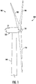
- FIG. 1 illustrates a perspective view of one embodiment of a portion of a wind turbine 100 according to the present disclosure that is configured to implement the method as described herein.
- the wind turbine 100 includes a nacelle 102 that typically houses a generator (not shown).
- the nacelle 102 is mounted on a tower 104 having any suitable height that facilitates operation of wind turbine 100 as described herein.
- the wind turbine 100 also includes a rotor 106 that includes three blades 108 attached to a rotating hub 110.
- the wind turbine 100 may include any number of blades 108 that facilitates operation of the wind turbine 100 as described herein.
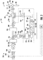
- FIG. 2 a schematic view of one embodiment of an electrical power system 200 that may be used with the wind turbine 100 is illustrated.
- the wind turbine 10 and the electrical power system 200 may be referred to herein collectively as a wind turbine power system 150.
- wind turbine power system 150 wind impacts the blades 108 and the blades 108 transform wind energy into a mechanical rotational torque that rotatably drives a low-speed shaft 112 (also referred to herein as a rotor shaft) via the hub 110.
- a low-speed shaft 112 also referred to herein as a rotor shaft
- the low-speed shaft 112 is configured to drive a gearbox 114 that subsequently steps up the low rotational speed of the low-speed shaft 112 to drive a high-speed shaft 116 (also referred to herein as a generator shaft) at an increased rotational speed.
- the high-speed shaft 116 is generally rotatably coupled to a generator 118 so as to rotatably drive a generator rotor 122 having field winding 125 ( FIG. 5 ).
- the generator 118 may be a wound rotor, three-phase, doubly-fed induction (asynchronous) generator (DFIG) that includes a generator stator 120 magnetically coupled to a generator rotor 122.
- DFIG doubly-fed induction
- a rotating magnetic field may be induced by the generator rotor 122 and a voltage may be induced within a generator stator 120 that is magnetically coupled to the generator rotor 122.
- the generator 118 is configured to convert the rotational mechanical energy to a sinusoidal, three-phase alternating current (AC) electrical energy signal in the generator stator 120.
- AC alternating current
- the associated electrical power can be transmitted to a main transformer 234 via a stator bus 208, a stator synchronizing switch 206, a system bus 216, a main transformer circuit breaker 214, and a generator-side bus 236.
- the main transformer 234 steps up the voltage amplitude of the electrical power such that the transformed electrical power may be further transmitted to a grid via a grid circuit breaker 238, a breaker-side bus 240, and a grid bus 242.
- the electrical power system 200 may include a controller 202 configured to control any of the components of the wind turbine 100 and/or implement the method steps as described herein.
- the controller 202 may include one or more processor(s) 204 and associated memory device(s) 207 configured to perform a variety of computer-implemented functions (e.g., performing the methods, steps, calculations and the like and storing relevant data as disclosed herein).
- the controller 202 may also include a communications module 209 to facilitate communications between the controller 202 and the various components of the wind turbine 100, e.g. any of the components of FIG. 2 .
- the communications module 209 may include a sensor interface 211 (e.g., one or more analog-to-digital converters) to permit signals transmitted from one or more sensors to be converted into signals that can be understood and processed by the processors 204.
- the sensors e.g. sensors 252, 254, 256, 258
- the sensors may be communicatively coupled to the communications module 209 using any suitable means.
- the sensors 252, 254, 256, 258 may be coupled to the sensor interface 211 via a wired connection.
- the sensors 252, 254, 256, 258 may be coupled to the sensor interface 211 via a wireless connection, such as by using any suitable wireless communications protocol known in the art.
- the processor 204 may be configured to receive one or more signals from the sensors.
- processor refers not only to integrated circuits referred to in the art as being included in a computer, but also refers to a controller, a microcontroller, a microcomputer, a programmable logic controller (PLC), an application specific integrated circuit, and other programmable circuits.
- the processor 204 is also configured to compute advanced control algorithms and communicate to a variety of Ethernet or serial-based protocols (Modbus, OPC, CAN, etc.).
- the memory device(s) 207 may generally comprise memory element(s) including, but not limited to, computer readable medium (e.g., random access memory (RAM)), computer readable non-volatile medium (e.g., a flash memory), a floppy disk, a compact disc-read only memory (CD-ROM), a magnetooptical disk (MOD), a digital versatile disc (DVD) and/or other suitable memory elements.
- RAM random access memory
- RAM computer readable non-volatile medium
- CD-ROM compact disc-read only memory
- MOD magnetooptical disk
- DVD digital versatile disc
- Such memory device(s) 207 may generally be configured to store suitable computer-readable instructions that, when implemented by the processor(s) 204, configure the controller 202 to perform the various functions as described herein.
- the generator stator 120 may be electrically coupled to a stator synchronizing switch 206 via a stator bus 208.
- the generator rotor 122 may be electrically coupled to a bi-directional power conversion assembly 210 or power converter via a rotor bus 212.
- the generator rotor 122 may be electrically coupled to the rotor bus 212 via any other device that facilitates operation of electrical power system 200 as described herein.
- the stator synchronizing switch 206 may be electrically coupled to a main transformer circuit breaker 214 via a system bus 216.
- the power conversion assembly 210 may include a first converter and a second converter.
- the first converter may be a rotor-side converter 220 and the second converter 22 may be a line-side converter 222.
- the power conversion assembly 210 may include a rotor filter 218 that is electrically coupled to the generator rotor 122 via the rotor bus 212.
- the rotor filter 218 may include a rotor-side reactor.
- a rotor filter bus 219 electrically couples the rotor filter 218 to the rotor-side power converter 220.
- the rotor-side power converter 220 may be electrically coupled to the line-side power converter 222 via a single direct current (DC) link 244.
- DC direct current
- the rotor-side power converter 220 and the line-side power converter 222 may be electrically coupled via individual and separate DC links.
- the DC link 244 may include a positive rail 246, a negative rail 248, and at least one capacitor 250 coupled therebetween.
- a line-side power converter bus 223 may electrically couple the line-side power converter 222 to a line filter 224.
- a line bus 225 may electrically couple the line filter 224 to a line contactor 226.
- the line filter 224 may include a line-side reactor.
- the line contactor 226 may be electrically coupled to a conversion circuit breaker 228 via a conversion circuit breaker bus 230.
- the conversion circuit breaker 228 may be electrically coupled to the main transformer circuit breaker 214 via system bus 216 and a connection bus 232.
- the main transformer circuit breaker 214 may be electrically coupled to an electric power main transformer 234 via a generator-side bus 236.
- the main transformer 234 may be electrically coupled to a grid circuit breaker 238 via a breaker-side bus 240.
- the grid circuit breaker 238 may be connected to the electric power transmission and distribution grid via a grid bus 242.
- alternating current (AC) power generated at the generator stator 120 by rotation of the rotor 106 is provided via a dual path to the grid bus 242.
- the dual paths are defined by the stator bus 208 and the rotor bus 212.
- sinusoidal multi-phase (e.g. three-phase) AC power is provided to the power conversion assembly 210.
- the rotor-side power converter 220 converts the AC power provided from the rotor bus 212 into DC power and provides the DC power to the DC link 244.
- Switching elements 245 e.g. IGBTs
- IGBTs used in bridge circuits of the rotor side power converter 220 can be modulated to convert the AC power provided from the rotor bus 212 into DC power suitable for the DC link 244.
- the line side converter 222 converts the DC power on the DC link 244 into AC output power suitable for the electrical grid bus 242.
- switching elements 247 e.g. IGBTs
- the AC power from the power conversion assembly 210 can be combined with the power from the stator 120 to provide multi-phase power (e.g. three-phase power) having a frequency maintained substantially at the frequency of the electrical grid bus 242 (e.g. 50 Hz/60 Hz).
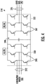
- FIG. 4 illustrates a simplified schematic diagram of one embodiment of a variable frequency drive (VFD) that maintains a constant electrical frequency output on the grid side of the generator 118.
- VFD variable frequency drive
- the VFD configuration includes a six-switch voltage-sourced rectifier on the rotor side converter 220, a DC link capacitor 244 to minimize DC voltage variation, and a six-switch voltage-sourced inverter utilizing pulse width modulation on the grid side.
- Rotor-side switching elements 245 are often diodes or silicon controlled rectifiers (SCR), while the grid side-switching elements 247 are often insulated gate bipolar transistors (IGBTs). As such, the magnitude and electrical frequency of the current supplied to the generator rotor 122 through the VFD may be varied to account for changes in the rotor shaft speed and to maintain a constant output on the generator stator winding.
- SCR silicon controlled rectifiers
- IGBTs insulated gate bipolar transistors
- the power conversion assembly 210 may be coupled in electronic data communication with the controller 202 and/or a separate or integral converter controller 262 to control the operation of the rotor-side power converter 220 and the line-side power converter 222.
- the controller 202 may be configured to receive one or more voltage and/or electric current measurement signals from the first set of voltage and electric current sensors 252.
- the controller 202 may be configured to monitor and control at least some of the operational variables associated with the wind turbine 100 via the sensors 252.
- each of the sensors 252 may be electrically coupled to each one of the three phases of the power grid bus 242.
- the sensors 252 may be electrically coupled to any portion of electrical power system 200 that facilitates operation of electrical power system 200 as described herein.
- the sensors may also include a second set of voltage and electric current sensors 254, a third set of voltage and electric current sensors 256, a fourth set of voltage and electric current sensors 258 (all shown in FIG. 2 ), and/or any other suitable sensors.
- any number or type of voltage and/or electric current sensors 252, 254, 256, 258 may be employed within the wind turbine 100 and at any location.
- the sensors may be current transformers, shunt sensors, rogowski coils, Hall Effect current sensors, Micro Inertial Measurement Units (MIMUs), or similar, and/or any other suitable voltage or electric current sensors now known or later developed in the art.
- MIMUs Micro Inertial Measurement Units
- the converter controller 262 is configured to receive one or more voltage and/or electric current feedback signals from the sensors 252, 254, 256, 258. More specifically, in certain embodiments, the current or voltage feedback signals may include at least one of line feedback signals, line-side converter feedback signals, rotor-side converter feedback signals, or stator feedback signals. For example, as shown in the illustrated embodiment, the converter controller 262 receives voltage and electric current measurement signals from the second set of voltage and electric current sensors 254 coupled in electronic data communication with stator bus 208. The converter controller 262 may also receive the third and fourth set of voltage and electric current measurement signals from the third and fourth set of voltage and electric current sensors 256, 258. In addition, the converter controller 262 may be configured with any of the features described herein in regards to the main controller 202. As such, the converter controller 262 is configured to implement the various method steps as described herein and may be configured similar to the controller 202.
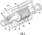
- FIG. 5 illustrates a perspective cross-sectional view of one embodiment of the generator 118 of the present disclosure, particularly illustrating a plurality of brushes 126 configured with the rotor 122 thereof; and
- FIG. 6 illustrates a flow diagram of one embodiment of a method 300 for preventing damage in a bearing, such as bearings 124, of the generator 118 of an electrical power system 200.
- the generator 118 may generally include a bearing housing 130 for housing the generator stator 120 and the generator rotor 122. Further, as shown, the generator rotor 122 includes the field winding 125 or coil. Moreover, as shown, the bearing housing 130 also generally includes bearing insulation 132 circumferentially arranged around the field winding 125. In addition, the generator 118 may further include one or more bearings 124 rotatably mounted into the high-speed shaft 116. Furthermore, the generator 118 may include one or more generator slip rings 128 with one or more brushes 126 secured thereto.
- brushes 126 are typically constructed from a graphite/metal composite that is pressed into rectangular bar shapes and are typically mounted on the non-drive end of the generator 118.
- the generator 118 may include any suitable number of brushes 126, including particularly at least one brush.
- the brushes 126 may be mounted perpendicular to the high-speed shaft 116.
- the brushes 126 may have any other suitable mounting configuration with respect to the generator rotor 122. As such, some of the brushes 126 may be used to pull AC voltage off of at least one of the generator slip rings 128, while the remaining brush(es) act as a controlled path to ground (i.e. a ground brush).
- the brushes 126 may be positioned radially outward of the generator slip ring(s) 128, with consecutive brushes in each set mounted 60 to 120 degrees apart.
- each brush 126 may be rigidly fixed in its axial position so as to minimize deflection under normal operational load.
- the brush holders may also use a constant pressure coil spring to maintain contact between the brush(es) 126 and the generator slip ring(s) 128.
- a micro switch may also be mounted at the base of the brush holder so as to trigger a warning signal if the brush has worn down too much.
- the ground brush 126 may be sized and oriented to engage the generator rotor 122 to facilitate providing an electrical connection from the generator rotor 122 to ground (not shown).
- the ground brush 126 is configured to protect the generator bearings 124 as well as all other components of the generator 118 from harmful electrical voltages and currents. More specifically, the ground brush 126 is configured to provide a low-impedance path around the bearings 124.
- the oil has a low dielectric capacity and breaks down quicker than the surrounding air or other dielectric materials. Once this voltage exceeds the dielectric capacity of the lubricating oil in the bearing, it will discharge in a pulse, causing an arc. This cycle will repeat as long as the ground brush 126 is lifted, causing pitting and fluting of the bearing track, ultimately leading to bearing failure. In addition, the aforementioned issues also cause damage to the bearing insulation 132.
- FIG. 6 a flow diagram of one embodiment of the method 300 for preventing damage in a bearing, such as bearings 124, of the generator 118 due to EDM is shown.
- the method 300 is described herein with reference to the wind turbine 10, the electrical power system 200, the controller 202, and the generator 118 illustrated in FIGS. 1-5 .
- the disclosed method 300 may be implemented with electrical power systems having any other suitable configurations.
- FIG. 6 depicts steps performed in a particular order for purposes of illustration and discussion, the methods discussed herein are not limited to any particular order or arrangement.
- One skilled in the art, using the disclosures provided herein, will appreciate that various steps of the methods disclosed herein can be omitted, rearranged, combined, and/or adapted in various ways without deviating from the scope of the present disclosure.
- the method 300 includes monitoring, via a controller (such as controller 202), one or more electrical signals of the power conversion assembly 210.
- the operating parameter(s) may include current and/or voltage collected from the rotor-side power converter 220 or the line-side converter 222.
- FIG.7 illustrates a detail method 400 that, as shown at (402), includes collecting three-phase currents and/or three-phase voltages from the rotor-side power converter 220 (I A , I B , and I C ).
- the controller 202 also calculates a complex fast Fourier transform (FFT) of the complex rotating vector.
- FFT complex fast Fourier transform
- the method 300 thus includes extracting, via the controller 202, one or more spectral components in frequency bands of the frequency domain around one or more known characteristic frequencies of the bearing 124.
- the controller 202 is also configured to calculate the bearing characteristic frequencies for the bearing dimensions and/or size.
- the method 300 further includes determining, via the controller 202, at least one characteristic of the spectral component(s) in the frequency bands. More specifically, as shown at (408) of FIG. 7 , the controller 202 may calculate one or more peak magnitudes of the spectral component(s) in the frequency bands. Moreover, as shown at (410), the controller may also calculate one or more entropies of the spectral component(s) in the frequency bands.
- the method 300 includes comparing, via the controller 202, the characteristic(s) of the spectral component(s) in the frequency bands to at least one baseline value. More specifically, as shown at (412) and (414) of FIG. 7 , in one embodiment, the controller 202 is configured to compare the one or more entropies to an entropy threshold and the one or more peak magnitudes to a magnitude threshold, respectively.
- the controller 202 may be configured to generate a high-dimensional vector including a plurality of characteristics and comparing the high-dimensional vector to a baseline cluster having similar vectors from a baseline generator. In such embodiments, deviations from the baseline cluster provides the health metric of the generator bearing.
- the method 300 includes generating, via the controller 202, a fault signal or a baseline signal for the bearing based on the comparison. More particularly, as shown at (416) of FIG. 7 , the controller 202 is configured to generate the fault signal when the one or more entropies exceeds the entropy threshold. In contrast, if the one or more entropies is less than the entropy threshold, as shown at (414), the controller 202 is configured to compare the one or more peak magnitudes to the magnitude threshold. Moreover, as shown at (416), the controller 202 is configured to generate the fault signal when the one or more peak magnitudes is less than the magnitude threshold. Further, as shown at (418), the controller 202 is configured to generate the baseline signal when the one or more entropies is less than the entropy threshold and the one or more peak magnitudes is greater than the magnitude threshold.
- increases in the one or more entropies and decreases in the one or more peak magnitudes indicates worsening of EDM damage in the bearing.
- FIG. 8 a graphical representation 500 of the impact of EDM on the current spectrum in a generator according to the present disclosure is illustrated.
- the graphical representation 500 depicts a frequency domain of a baseline bearing spectrum 502 and a faulty bearing spectrum 504.
- the graphical representation 500 illustrates how the faulty bearing spectrum 504 has increased entropy and a lower peak magnitude than the baseline bearing spectrum 502.
- the method 300 includes implementing, via the controller 202, a control action.
- the control action may include changing an operating set point of the wind turbine 10, shutting down the wind turbine 10, generating an alarm, scheduling a repair, replacing at least one of the bearing insulation 132 or the ground brush 126, and/or any other suitable action.
- the method 600 includes collecting three-phase currents and/or three-phase voltages from the rotor-side power converter 220 and/or the line-side converter 222 (e.g., I A , I B , and I C ).
- the present disclosure also encompasses utilizing spectral information from other quantities derived from voltages and current, such as instantaneous real power, reactive power, etc., which can be used for PMGs and/or other types of electrical machines.
- the method 600 includes calculating a complex FFT of the complex rotating vector.
- the controller 202 is also configured to calculate the bearing characteristic frequencies for the bearing dimensions and/or size.
- the method 600 includes extracting spectral components in frequency bands around the bearing characteristic frequencies.
- the method 600 then monitors the peak magnitudes of the spectral components and tracks the location of the peak magnitudes in the frequency bands around the bearing characteristic frequencies.
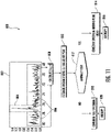
- the method 600 includes determining whether the peak location has changed. If so, as shown at (614), the controller 202 is configured to indicate that a friction changed has occurred in the bearing. If not, the method proceeds to (616) and determines whether the peak magnitude has changed. If so, as shown at (618), the controller 202 is configured to indicate that bearing damage has started. If not, as shown at (620), the controller 202 is configured to indicate that the bearing is representative of a baseline generator (e.g., the bearing is healthy and/or able to continue operating as-is).
- a baseline generator e.g., the bearing is healthy and/or able to continue operating as-is
- a graphical representation 700 of the impact of lubricant degradation on the current spectrum in a generator according to the present disclosure is illustrated.
- the graphical representation 700 depicts a frequency domain of spectral components in frequency bands of the bearing. More specifically, as shown, the graphical representation 700 illustrates arrow 702 that depicts the increase of the characteristic frequency with improving lubricant health.
- FIG. 11 illustrates a flow diagram of yet another embodiment of a method 800 for preventing damage in a bearing of a generator according to the present disclosure.
- the plot 802 illustrates baseline 804 and faulty 806 frequency component movement for the same generator speed and compares the entropies of the healthy and faulty components.
- the method 800 calculates the peak magnitude and angle of each of the healthy and faulty components.
- the method 800 includes estimating the anomaly level of the peak values.
- the method 800 includes determining whether the peak is high enough. If yes, as shown at (814) and (816), the method 800 includes considering the spectrum around the peak and determining the entropy thereof. If no, as shown at (818) and (820), the method 800 includes considering the full spectrum and determining the entropy thereof.
Landscapes
- Engineering & Computer Science (AREA)
- Power Engineering (AREA)
- Life Sciences & Earth Sciences (AREA)
- Sustainable Development (AREA)
- Sustainable Energy (AREA)
- Chemical & Material Sciences (AREA)
- Combustion & Propulsion (AREA)
- Mechanical Engineering (AREA)
- General Engineering & Computer Science (AREA)
- Control Of Eletrric Generators (AREA)
- Wind Motors (AREA)
Applications Claiming Priority (1)
| Application Number | Priority Date | Filing Date | Title |
|---|---|---|---|
| US17/222,008 US11539317B2 (en) | 2021-04-05 | 2021-04-05 | System and method for detecting degradation in wind turbine generator bearings |
Publications (2)
| Publication Number | Publication Date |
|---|---|
| EP4072004A1 true EP4072004A1 (de) | 2022-10-12 |
| EP4072004B1 EP4072004B1 (de) | 2024-12-04 |
Family
ID=80999471
Family Applications (1)
| Application Number | Title | Priority Date | Filing Date |
|---|---|---|---|
| EP22165510.3A Active EP4072004B1 (de) | 2021-04-05 | 2022-03-30 | System und verfahren zur erkennung von schäden an windturbinengeneratorlagern |
Country Status (5)
| Country | Link |
|---|---|
| US (1) | US11539317B2 (de) |
| EP (1) | EP4072004B1 (de) |
| CN (1) | CN115199478A (de) |
| DK (1) | DK4072004T3 (de) |
| ES (1) | ES3015481T3 (de) |
Families Citing this family (1)
| Publication number | Priority date | Publication date | Assignee | Title |
|---|---|---|---|---|
| US11905927B2 (en) * | 2020-04-30 | 2024-02-20 | Vestas Wind Systems A/S | Frequency content based monitoring of wind turbine blade pitch system |
Citations (2)
| Publication number | Priority date | Publication date | Assignee | Title |
|---|---|---|---|---|
| US20130049733A1 (en) * | 2011-08-29 | 2013-02-28 | General Electric Company | Fault detection based on current signature analysis for a generator |
| US20170328349A1 (en) * | 2016-05-12 | 2017-11-16 | General Electric Company | System and method for detecting pitch bearing damage in a wind turbine |
Family Cites Families (49)
| Publication number | Priority date | Publication date | Assignee | Title |
|---|---|---|---|---|
| NL7503934A (en) | 1975-04-02 | 1975-07-31 | Mobil Oil Corp | IC engine failure prediction method - using separating devices in lubricating system to monitor metal particle presence |
| JPS61248999A (ja) | 1985-04-26 | 1986-11-06 | Tech Res Assoc Highly Reliab Marine Propul Plant | 潤滑機能部品の故障予知・監視方法 |
| JPS62223406A (ja) | 1986-03-20 | 1987-10-01 | Toshiba Corp | 潤滑油劣化監視装置 |
| JPH0634541A (ja) | 1992-07-14 | 1994-02-08 | Nippon Oil Co Ltd | 潤滑油劣化モニター装置 |
| CN2520415Y (zh) | 2001-10-18 | 2002-11-13 | 朱菊根 | 内燃机润滑油故障监控仪 |
| US7635596B2 (en) | 2004-12-15 | 2009-12-22 | Rohm And Haas Company | Method for monitoring degradation of lubricating oils |
| US20190156600A1 (en) | 2006-11-16 | 2019-05-23 | Ge Global Sourcing Llc | Locomotive sensor system for monitoring engine and lubricant health |
| JP2008275494A (ja) | 2007-05-01 | 2008-11-13 | Toshiba Corp | 潤滑剤および粘稠性物質の劣化診断方法およびその診断装置 |
| DE102008021360A1 (de) * | 2008-04-29 | 2009-11-05 | Siemens Aktiengesellschaft | Verfahren und Vorrichtung zum Erkennen eines Lagerschadens |
| KR20120112408A (ko) | 2009-11-25 | 2012-10-11 | 이데미쓰 고산 가부시키가이샤 | 윤활유의 열화도 측정 방법 및 그의 측정 장치, 및 기계?장치에 있어서의 윤활유 감시 시스템 |
| JP5725833B2 (ja) | 2010-01-04 | 2015-05-27 | Ntn株式会社 | 転がり軸受の異常診断装置、風力発電装置および異常診断システム |
| US8734105B2 (en) | 2010-09-16 | 2014-05-27 | Vestas Wind Systems A/S | Control system for a wind turbine and method of operating a wind turbine based on monitoring a bearing |
| US20120179388A1 (en) | 2011-01-07 | 2012-07-12 | International Business Machines Corporation | System, method and program for early detection of fan failure by monitoring grease degradation |
| CN202033191U (zh) | 2011-04-08 | 2011-11-09 | 洛阳轴研科技股份有限公司 | 基于物联网的智能型风力发电机轴承监测系统 |
| JP5973227B2 (ja) | 2012-05-11 | 2016-08-23 | 株式会社日立製作所 | グリースの劣化診断装置、およびグリースのメンテナンス方法 |
| EP2708741B1 (de) | 2012-09-12 | 2015-04-15 | Siemens Aktiengesellschaft | Verfahren und Anordnung zur Überwachung eines Lagers einer Windturbine |
| JP6234757B2 (ja) | 2013-09-24 | 2017-11-22 | Ntn株式会社 | ギヤ用潤滑油劣化検知装置および風力発電装置の状態監視システム |
| NO3070262T3 (de) | 2014-04-02 | 2018-06-02 | ||
| CN203856904U (zh) | 2014-05-28 | 2014-10-01 | 浙江师范大学 | 一种用于风力发电机的转速自监测的球轴承 |
| CN103982556B (zh) | 2014-05-28 | 2016-05-04 | 浙江师范大学 | 一种用于风力发电机的转速自监测的球轴承 |
| WO2015198793A1 (ja) | 2014-06-24 | 2015-12-30 | Ntn株式会社 | 状態監視システムおよびそれを用いた風力発電システム |
| JP6308922B2 (ja) | 2014-09-17 | 2018-04-11 | Ntn株式会社 | 転がり軸受の異常診断装置、風力発電装置、及び転がり軸受の異常診断方法 |
| KR20160034634A (ko) | 2014-09-22 | 2016-03-30 | 한국전력공사 | 실시간 윤활유 열화상태 진단 장치 |
| CN204204181U (zh) | 2014-10-14 | 2015-03-11 | 大唐(赤峰)新能源有限公司 | 一种用于风电机组偏航滑动轴承监测的远程数据采集系统 |
| CN204177367U (zh) | 2014-10-27 | 2015-02-25 | 北京金风科创风电设备有限公司 | 风力发电机组、其轴承位移监测结构及系统 |
| WO2016072290A1 (ja) | 2014-11-07 | 2016-05-12 | Ntn株式会社 | 軸受装置、機械装置、軸受、軸受の状態監視装置、軸受監視システム及び風力発電設備 |
| CN104459388B (zh) * | 2014-11-26 | 2017-02-22 | 国家电网公司 | 一种永磁直驱风力发电系统一体化故障诊断方法 |
| CN107448362B (zh) | 2016-05-31 | 2018-11-20 | 北京金风科创风电设备有限公司 | 回转支承轴承的状态监测方法、装置及风力发电机组 |
| CN106198020A (zh) | 2016-07-07 | 2016-12-07 | 华北电力大学(保定) | 基于子空间和模糊c均值聚类的风电机组轴承故障诊断法 |
| CN206056648U (zh) | 2016-09-06 | 2017-03-29 | 大唐(赤峰)新能源有限公司 | 一种风电机组发电机轴承状态监测系统 |
| CN106338397A (zh) | 2016-09-30 | 2017-01-18 | 哈尔滨理工大学 | 基于无传感器检测法的风力发电机滚动轴承故障诊断装置 |
| CN206399365U (zh) | 2016-11-28 | 2017-08-11 | 北京金风科创风电设备有限公司 | 用于监测轴承轴向游隙的监测装置以及风力发电机组 |
| DK3343030T3 (da) | 2016-12-22 | 2021-02-08 | Eolotec Gmbh | Anordning og fremgangsmåde til overvågning af et bladleje i en vindturbine |
| CN106679977A (zh) | 2017-01-03 | 2017-05-17 | 国电联合动力技术有限公司 | 一种风电机组变桨轴承监控方法及装置 |
| US10852214B2 (en) * | 2017-05-19 | 2020-12-01 | Nutech Ventures | Detecting faults in wind turbines |
| CN206818646U (zh) | 2017-06-23 | 2017-12-29 | 北京金风科创风电设备有限公司 | 轴承裂纹监测系统及风力发电机组 |
| JP7099816B2 (ja) | 2017-10-27 | 2022-07-12 | 株式会社日立製作所 | 潤滑油の劣化診断方法、回転機械の潤滑油の監視システムおよび方法 |
| CN207701297U (zh) | 2017-12-15 | 2018-08-07 | 远景能源(江苏)有限公司 | 监测风力发电机组叶片轴承外圈螺栓断裂的装置 |
| DE102017223418B4 (de) | 2017-12-20 | 2023-05-25 | Zf Friedrichshafen Ag | Modellbasiertes Verfahren und System zur Zustandsüberwachung eines Gleitlagers, insbesondere für Windkraftanlagen |
| US11473564B2 (en) | 2018-01-18 | 2022-10-18 | General Electric Company | System and method for monitoring a wind turbine pitch bearing |
| CN108344574B (zh) | 2018-04-28 | 2019-09-10 | 湖南科技大学 | 一种基于深度联合适配网络的风电机组轴承故障诊断方法 |
| CN108894932B (zh) | 2018-05-28 | 2020-07-10 | 国电联合动力技术有限公司 | 一种风电机组发电机轴承故障智能诊断系统及方法 |
| CN110554090A (zh) | 2018-05-31 | 2019-12-10 | 北京金风科创风电设备有限公司 | 风电机组及其变桨轴承的裂纹监测系统和方法 |
| CN108932580A (zh) | 2018-06-05 | 2018-12-04 | 浙江运达风电股份有限公司 | 基于数据建模的风电机组变桨轴承磨损监测和预警方法 |
| CN108844742B (zh) * | 2018-09-06 | 2020-08-18 | 国电联合动力技术有限公司 | 一种风电机组发电机轴承润滑状态监测方法和系统 |
| CN109033719B (zh) | 2018-09-12 | 2023-05-12 | 温州大学苍南研究院 | 一种风力涡轮机轴承故障诊断方法 |
| CN109387546B (zh) | 2018-11-01 | 2020-06-02 | 西安交通大学 | 一种基于量子点气敏传感器的轴承润滑脂失效监测方法 |
| CN209212469U (zh) | 2018-12-06 | 2019-08-06 | 北京金风科创风电设备有限公司 | 用于监测变桨轴承的监测装置、监测系统及风力发电机组 |
| CN109655266B (zh) | 2018-12-11 | 2021-12-10 | 内蒙古工业大学 | 一种基于avmd和谱相关分析的风电机组轴承故障诊断方法 |
-
2021
- 2021-04-05 US US17/222,008 patent/US11539317B2/en active Active
-
2022
- 2022-03-30 EP EP22165510.3A patent/EP4072004B1/de active Active
- 2022-03-30 DK DK22165510.3T patent/DK4072004T3/da active
- 2022-03-30 ES ES22165510T patent/ES3015481T3/es active Active
- 2022-04-01 CN CN202210340011.9A patent/CN115199478A/zh active Pending
Patent Citations (2)
| Publication number | Priority date | Publication date | Assignee | Title |
|---|---|---|---|---|
| US20130049733A1 (en) * | 2011-08-29 | 2013-02-28 | General Electric Company | Fault detection based on current signature analysis for a generator |
| US20170328349A1 (en) * | 2016-05-12 | 2017-11-16 | General Electric Company | System and method for detecting pitch bearing damage in a wind turbine |
Also Published As
| Publication number | Publication date |
|---|---|
| US20220321040A1 (en) | 2022-10-06 |
| US11539317B2 (en) | 2022-12-27 |
| EP4072004B1 (de) | 2024-12-04 |
| ES3015481T3 (en) | 2025-05-05 |
| DK4072004T3 (da) | 2025-03-10 |
| CN115199478A (zh) | 2022-10-18 |
Similar Documents
| Publication | Publication Date | Title |
|---|---|---|
| EP4071357B1 (de) | System und verfahren zur erfassung des zustands der lagerisolierung und der massebürste in einem generator | |
| US10138872B2 (en) | System and method for detecting ground brush lifting | |
| US9671442B2 (en) | System and method for detecting a grid event | |
| US8039982B2 (en) | Method for operating a wind turbine, coil arrangement for an electric machine, and controller for a wind turbine | |
| EP2400150A2 (de) | Überdrehzahlschutzsystem und -verfahren für Windturbinen | |
| US9577421B2 (en) | System and method for isolating ground faults in a wind turbine | |
| EP2762720A2 (de) | Verfahren zur Optimierung des Betriebs einer Windturbine | |
| US8451573B1 (en) | Overvoltage protection device for a wind turbine and method | |
| US10054108B2 (en) | Wind turbine system and method for controlling a wind turbine system by power monitoring | |
| Hamatwi et al. | Condition monitoring and fault diagnosis of stator and rotor interturn winding faults in a DFIG-based wind turbine system: A Review | |
| EP4072004B1 (de) | System und verfahren zur erkennung von schäden an windturbinengeneratorlagern | |
| EP4407861A1 (de) | System und verfahren zur erkennung der lagerisolierung und des zustands der erdungsbürste in einem generator | |
| Al-Ahmar et al. | DFIG-based wind turbine fault diagnosis using a specific discrete wavelet transform | |
| Faiz et al. | Review of eccentricity fault detection techniques in IMs focusing on DFIG | |
| US11013070B2 (en) | System and method for controlling multiple IGBT temperatures in a power converter of an electrical power system | |
| Iorgulescu et al. | Faults diagnosis for electrical machines based on analysis of motor current | |
| EP3745588B1 (de) | Doppelfrequenzfilter zur unterscheidung zwischen verschiedenen arten von netzereignissen | |
| US20170074247A1 (en) | Current limit calculation for wind turbine control | |
| Jha et al. | Inverter Based Measurements of Common Mode Power to monitor Arching in Bearings of Wound Rotor Machine | |
| Meira et al. | Fault detection in starter resistor of large wound rotor induction motor: A case study | |
| WO2024132264A1 (en) | Computer-implemented method for monitoring a generator of a wind turbine, wind turbine, computer program and electronically readable storage medium |
Legal Events
| Date | Code | Title | Description |
|---|---|---|---|
| PUAI | Public reference made under article 153(3) epc to a published international application that has entered the european phase |
Free format text: ORIGINAL CODE: 0009012 |
|
| STAA | Information on the status of an ep patent application or granted ep patent |
Free format text: STATUS: THE APPLICATION HAS BEEN PUBLISHED |
|
| AK | Designated contracting states |
Kind code of ref document: A1 Designated state(s): AL AT BE BG CH CY CZ DE DK EE ES FI FR GB GR HR HU IE IS IT LI LT LU LV MC MK MT NL NO PL PT RO RS SE SI SK SM TR |
|
| STAA | Information on the status of an ep patent application or granted ep patent |
Free format text: STATUS: REQUEST FOR EXAMINATION WAS MADE |
|
| 17P | Request for examination filed |
Effective date: 20230317 |
|
| RBV | Designated contracting states (corrected) |
Designated state(s): AL AT BE BG CH CY CZ DE DK EE ES FI FR GB GR HR HU IE IS IT LI LT LU LV MC MK MT NL NO PL PT RO RS SE SI SK SM TR |
|
| P01 | Opt-out of the competence of the unified patent court (upc) registered |
Effective date: 20230530 |
|
| GRAP | Despatch of communication of intention to grant a patent |
Free format text: ORIGINAL CODE: EPIDOSNIGR1 |
|
| STAA | Information on the status of an ep patent application or granted ep patent |
Free format text: STATUS: GRANT OF PATENT IS INTENDED |
|
| INTG | Intention to grant announced |
Effective date: 20240315 |
|
| RAP3 | Party data changed (applicant data changed or rights of an application transferred) |
Owner name: GENERAL ELECTRIC RENOVABLES ESPANA S.L. |
|
| GRAJ | Information related to disapproval of communication of intention to grant by the applicant or resumption of examination proceedings by the epo deleted |
Free format text: ORIGINAL CODE: EPIDOSDIGR1 |
|
| STAA | Information on the status of an ep patent application or granted ep patent |
Free format text: STATUS: REQUEST FOR EXAMINATION WAS MADE |
|
| GRAP | Despatch of communication of intention to grant a patent |
Free format text: ORIGINAL CODE: EPIDOSNIGR1 |
|
| STAA | Information on the status of an ep patent application or granted ep patent |
Free format text: STATUS: GRANT OF PATENT IS INTENDED |
|
| INTC | Intention to grant announced (deleted) | ||
| INTG | Intention to grant announced |
Effective date: 20240801 |
|
| GRAS | Grant fee paid |
Free format text: ORIGINAL CODE: EPIDOSNIGR3 |
|
| GRAA | (expected) grant |
Free format text: ORIGINAL CODE: 0009210 |
|
| STAA | Information on the status of an ep patent application or granted ep patent |
Free format text: STATUS: THE PATENT HAS BEEN GRANTED |
|
| AK | Designated contracting states |
Kind code of ref document: B1 Designated state(s): AL AT BE BG CH CY CZ DE DK EE ES FI FR GB GR HR HU IE IS IT LI LT LU LV MC MK MT NL NO PL PT RO RS SE SI SK SM TR |
|
| REG | Reference to a national code |
Ref country code: CH Ref legal event code: EP |
|
| REG | Reference to a national code |
Ref country code: DE Ref legal event code: R096 Ref document number: 602022008294 Country of ref document: DE |
|
| REG | Reference to a national code |
Ref country code: IE Ref legal event code: FG4D |
|
| REG | Reference to a national code |
Ref country code: DK Ref legal event code: T3 Effective date: 20250303 |
|
| REG | Reference to a national code |
Ref country code: LT Ref legal event code: MG9D |
|
| REG | Reference to a national code |
Ref country code: NL Ref legal event code: MP Effective date: 20241204 |
|
| PG25 | Lapsed in a contracting state [announced via postgrant information from national office to epo] |
Ref country code: HR Free format text: LAPSE BECAUSE OF FAILURE TO SUBMIT A TRANSLATION OF THE DESCRIPTION OR TO PAY THE FEE WITHIN THE PRESCRIBED TIME-LIMIT Effective date: 20241204 |
|
| PG25 | Lapsed in a contracting state [announced via postgrant information from national office to epo] |
Ref country code: FI Free format text: LAPSE BECAUSE OF FAILURE TO SUBMIT A TRANSLATION OF THE DESCRIPTION OR TO PAY THE FEE WITHIN THE PRESCRIBED TIME-LIMIT Effective date: 20241204 |
|
| PG25 | Lapsed in a contracting state [announced via postgrant information from national office to epo] |
Ref country code: BG Free format text: LAPSE BECAUSE OF FAILURE TO SUBMIT A TRANSLATION OF THE DESCRIPTION OR TO PAY THE FEE WITHIN THE PRESCRIBED TIME-LIMIT Effective date: 20241204 |
|
| PG25 | Lapsed in a contracting state [announced via postgrant information from national office to epo] |
Ref country code: NO Free format text: LAPSE BECAUSE OF FAILURE TO SUBMIT A TRANSLATION OF THE DESCRIPTION OR TO PAY THE FEE WITHIN THE PRESCRIBED TIME-LIMIT Effective date: 20250304 |
|
| PG25 | Lapsed in a contracting state [announced via postgrant information from national office to epo] |
Ref country code: LV Free format text: LAPSE BECAUSE OF FAILURE TO SUBMIT A TRANSLATION OF THE DESCRIPTION OR TO PAY THE FEE WITHIN THE PRESCRIBED TIME-LIMIT Effective date: 20241204 Ref country code: GR Free format text: LAPSE BECAUSE OF FAILURE TO SUBMIT A TRANSLATION OF THE DESCRIPTION OR TO PAY THE FEE WITHIN THE PRESCRIBED TIME-LIMIT Effective date: 20250305 |
|
| PG25 | Lapsed in a contracting state [announced via postgrant information from national office to epo] |
Ref country code: RS Free format text: LAPSE BECAUSE OF FAILURE TO SUBMIT A TRANSLATION OF THE DESCRIPTION OR TO PAY THE FEE WITHIN THE PRESCRIBED TIME-LIMIT Effective date: 20250304 |
|
| PG25 | Lapsed in a contracting state [announced via postgrant information from national office to epo] |
Ref country code: NL Free format text: LAPSE BECAUSE OF FAILURE TO SUBMIT A TRANSLATION OF THE DESCRIPTION OR TO PAY THE FEE WITHIN THE PRESCRIBED TIME-LIMIT Effective date: 20241204 |
|
| REG | Reference to a national code |
Ref country code: AT Ref legal event code: MK05 Ref document number: 1749223 Country of ref document: AT Kind code of ref document: T Effective date: 20241204 |
|
| PG25 | Lapsed in a contracting state [announced via postgrant information from national office to epo] |
Ref country code: SM Free format text: LAPSE BECAUSE OF FAILURE TO SUBMIT A TRANSLATION OF THE DESCRIPTION OR TO PAY THE FEE WITHIN THE PRESCRIBED TIME-LIMIT Effective date: 20241204 |
|
| PG25 | Lapsed in a contracting state [announced via postgrant information from national office to epo] |
Ref country code: PL Free format text: LAPSE BECAUSE OF FAILURE TO SUBMIT A TRANSLATION OF THE DESCRIPTION OR TO PAY THE FEE WITHIN THE PRESCRIBED TIME-LIMIT Effective date: 20241204 |
|
| PGFP | Annual fee paid to national office [announced via postgrant information from national office to epo] |
Ref country code: ES Payment date: 20250401 Year of fee payment: 4 |
|
| PG25 | Lapsed in a contracting state [announced via postgrant information from national office to epo] |
Ref country code: IS Free format text: LAPSE BECAUSE OF FAILURE TO SUBMIT A TRANSLATION OF THE DESCRIPTION OR TO PAY THE FEE WITHIN THE PRESCRIBED TIME-LIMIT Effective date: 20250404 |
|
| PG25 | Lapsed in a contracting state [announced via postgrant information from national office to epo] |
Ref country code: PT Free format text: LAPSE BECAUSE OF FAILURE TO SUBMIT A TRANSLATION OF THE DESCRIPTION OR TO PAY THE FEE WITHIN THE PRESCRIBED TIME-LIMIT Effective date: 20250404 |
|
| PG25 | Lapsed in a contracting state [announced via postgrant information from national office to epo] |
Ref country code: EE Free format text: LAPSE BECAUSE OF FAILURE TO SUBMIT A TRANSLATION OF THE DESCRIPTION OR TO PAY THE FEE WITHIN THE PRESCRIBED TIME-LIMIT Effective date: 20241204 |
|
| PG25 | Lapsed in a contracting state [announced via postgrant information from national office to epo] |
Ref country code: AT Free format text: LAPSE BECAUSE OF FAILURE TO SUBMIT A TRANSLATION OF THE DESCRIPTION OR TO PAY THE FEE WITHIN THE PRESCRIBED TIME-LIMIT Effective date: 20241204 Ref country code: RO Free format text: LAPSE BECAUSE OF FAILURE TO SUBMIT A TRANSLATION OF THE DESCRIPTION OR TO PAY THE FEE WITHIN THE PRESCRIBED TIME-LIMIT Effective date: 20241204 |
|
| PG25 | Lapsed in a contracting state [announced via postgrant information from national office to epo] |
Ref country code: SK Free format text: LAPSE BECAUSE OF FAILURE TO SUBMIT A TRANSLATION OF THE DESCRIPTION OR TO PAY THE FEE WITHIN THE PRESCRIBED TIME-LIMIT Effective date: 20241204 |
|
| PG25 | Lapsed in a contracting state [announced via postgrant information from national office to epo] |
Ref country code: CZ Free format text: LAPSE BECAUSE OF FAILURE TO SUBMIT A TRANSLATION OF THE DESCRIPTION OR TO PAY THE FEE WITHIN THE PRESCRIBED TIME-LIMIT Effective date: 20241204 |
|
| PG25 | Lapsed in a contracting state [announced via postgrant information from national office to epo] |
Ref country code: IT Free format text: LAPSE BECAUSE OF FAILURE TO SUBMIT A TRANSLATION OF THE DESCRIPTION OR TO PAY THE FEE WITHIN THE PRESCRIBED TIME-LIMIT Effective date: 20241204 |
|
| REG | Reference to a national code |
Ref country code: DE Ref legal event code: R097 Ref document number: 602022008294 Country of ref document: DE |
|
| PG25 | Lapsed in a contracting state [announced via postgrant information from national office to epo] |
Ref country code: SE Free format text: LAPSE BECAUSE OF FAILURE TO SUBMIT A TRANSLATION OF THE DESCRIPTION OR TO PAY THE FEE WITHIN THE PRESCRIBED TIME-LIMIT Effective date: 20241204 |
|
| PLBE | No opposition filed within time limit |
Free format text: ORIGINAL CODE: 0009261 |
|
| STAA | Information on the status of an ep patent application or granted ep patent |
Free format text: STATUS: NO OPPOSITION FILED WITHIN TIME LIMIT |
|
| PG25 | Lapsed in a contracting state [announced via postgrant information from national office to epo] |
Ref country code: MC Free format text: LAPSE BECAUSE OF FAILURE TO SUBMIT A TRANSLATION OF THE DESCRIPTION OR TO PAY THE FEE WITHIN THE PRESCRIBED TIME-LIMIT Effective date: 20241204 |
|
| REG | Reference to a national code |
Ref country code: CH Ref legal event code: L10 Free format text: ST27 STATUS EVENT CODE: U-0-0-L10-L00 (AS PROVIDED BY THE NATIONAL OFFICE) Effective date: 20251015 |
|
| REG | Reference to a national code |
Ref country code: CH Ref legal event code: H13 Free format text: ST27 STATUS EVENT CODE: U-0-0-H10-H13 (AS PROVIDED BY THE NATIONAL OFFICE) Effective date: 20251023 |
|
| 26N | No opposition filed |
Effective date: 20250905 |
|
| PG25 | Lapsed in a contracting state [announced via postgrant information from national office to epo] |
Ref country code: LU Free format text: LAPSE BECAUSE OF NON-PAYMENT OF DUE FEES Effective date: 20250330 |
|
| REG | Reference to a national code |
Ref country code: BE Ref legal event code: MM Effective date: 20250331 |
|
| PG25 | Lapsed in a contracting state [announced via postgrant information from national office to epo] |
Ref country code: FR Free format text: LAPSE BECAUSE OF NON-PAYMENT OF DUE FEES Effective date: 20250331 |
|
| PG25 | Lapsed in a contracting state [announced via postgrant information from national office to epo] |
Ref country code: BE Free format text: LAPSE BECAUSE OF NON-PAYMENT OF DUE FEES Effective date: 20250331 |
|
| PG25 | Lapsed in a contracting state [announced via postgrant information from national office to epo] |
Ref country code: CH Free format text: LAPSE BECAUSE OF NON-PAYMENT OF DUE FEES Effective date: 20250331 |
|
| PG25 | Lapsed in a contracting state [announced via postgrant information from national office to epo] |
Ref country code: IE Free format text: LAPSE BECAUSE OF NON-PAYMENT OF DUE FEES Effective date: 20250330 |
|
| PGFP | Annual fee paid to national office [announced via postgrant information from national office to epo] |
Ref country code: DK Payment date: 20260219 Year of fee payment: 5 Ref country code: DE Payment date: 20260219 Year of fee payment: 5 |