EP4069596B1 - Deckelloser behälter und verfahren zum zusammenbau des behälters - Google Patents
Deckelloser behälter und verfahren zum zusammenbau des behälters Download PDFInfo
- Publication number
- EP4069596B1 EP4069596B1 EP20828036.2A EP20828036A EP4069596B1 EP 4069596 B1 EP4069596 B1 EP 4069596B1 EP 20828036 A EP20828036 A EP 20828036A EP 4069596 B1 EP4069596 B1 EP 4069596B1
- Authority
- EP
- European Patent Office
- Prior art keywords
- protrusions
- container
- protrusion
- opening
- une
- Prior art date
- Legal status (The legal status is an assumption and is not a legal conclusion. Google has not performed a legal analysis and makes no representation as to the accuracy of the status listed.)
- Active
Links
Images


Classifications
-
- B—PERFORMING OPERATIONS; TRANSPORTING
- B65—CONVEYING; PACKING; STORING; HANDLING THIN OR FILAMENTARY MATERIAL
- B65D—CONTAINERS FOR STORAGE OR TRANSPORT OF ARTICLES OR MATERIALS, e.g. BAGS, BARRELS, BOTTLES, BOXES, CANS, CARTONS, CRATES, DRUMS, JARS, TANKS, HOPPERS, FORWARDING CONTAINERS; ACCESSORIES, CLOSURES, OR FITTINGS THEREFOR; PACKAGING ELEMENTS; PACKAGES
- B65D3/00—Rigid or semi-rigid containers having bodies or peripheral walls of curved or partially-curved cross-section made by winding or bending paper without folding along defined lines
- B65D3/10—Rigid or semi-rigid containers having bodies or peripheral walls of curved or partially-curved cross-section made by winding or bending paper without folding along defined lines characterised by form of integral or permanently secured end closure
- B65D3/20—Rigid or semi-rigid containers having bodies or peripheral walls of curved or partially-curved cross-section made by winding or bending paper without folding along defined lines characterised by form of integral or permanently secured end closure with end portion of body adapted to be closed, by flattening or folding operations, e.g. formed with crease lines or flaps
-
- B—PERFORMING OPERATIONS; TRANSPORTING
- B31—MAKING ARTICLES OF PAPER, CARDBOARD OR MATERIAL WORKED IN A MANNER ANALOGOUS TO PAPER; WORKING PAPER, CARDBOARD OR MATERIAL WORKED IN A MANNER ANALOGOUS TO PAPER
- B31B—MAKING CONTAINERS OF PAPER, CARDBOARD OR MATERIAL WORKED IN A MANNER ANALOGOUS TO PAPER
- B31B50/00—Making rigid or semi-rigid containers, e.g. boxes or cartons
- B31B50/74—Auxiliary operations
- B31B50/742—Coating; Impregnating; Waterproofing; Decoating
- B31B50/743—Coating or impregnating edges or corners
-
- B—PERFORMING OPERATIONS; TRANSPORTING
- B65—CONVEYING; PACKING; STORING; HANDLING THIN OR FILAMENTARY MATERIAL
- B65B—MACHINES, APPARATUS OR DEVICES FOR, OR METHODS OF, PACKAGING ARTICLES OR MATERIALS; UNPACKING
- B65B3/00—Packaging plastic material, semiliquids, liquids or mixed solids and liquids, in individual containers or receptacles, e.g. bags, sacks, boxes, cartons, cans, or jars
- B65B3/02—Machines characterised by the incorporation of means for making the containers or receptacles
- B65B3/027—Making containers from separate body and end-parts
-
- B—PERFORMING OPERATIONS; TRANSPORTING
- B65—CONVEYING; PACKING; STORING; HANDLING THIN OR FILAMENTARY MATERIAL
- B65B—MACHINES, APPARATUS OR DEVICES FOR, OR METHODS OF, PACKAGING ARTICLES OR MATERIALS; UNPACKING
- B65B3/00—Packaging plastic material, semiliquids, liquids or mixed solids and liquids, in individual containers or receptacles, e.g. bags, sacks, boxes, cartons, cans, or jars
- B65B3/04—Methods of, or means for, filling the material into the containers or receptacles
- B65B3/06—Methods of, or means for, filling the material into the containers or receptacles by gravity flow
-
- B—PERFORMING OPERATIONS; TRANSPORTING
- B65—CONVEYING; PACKING; STORING; HANDLING THIN OR FILAMENTARY MATERIAL
- B65B—MACHINES, APPARATUS OR DEVICES FOR, OR METHODS OF, PACKAGING ARTICLES OR MATERIALS; UNPACKING
- B65B7/00—Closing containers or receptacles after filling
- B65B7/16—Closing semi-rigid or rigid containers or receptacles not deformed by, or not taking-up shape of, contents, e.g. boxes or cartons
- B65B7/18—Closing semi-rigid or rigid containers or receptacles not deformed by, or not taking-up shape of, contents, e.g. boxes or cartons by collapsing mouth portion and subsequently folding-down or securing flaps
-
- B—PERFORMING OPERATIONS; TRANSPORTING
- B65—CONVEYING; PACKING; STORING; HANDLING THIN OR FILAMENTARY MATERIAL
- B65D—CONTAINERS FOR STORAGE OR TRANSPORT OF ARTICLES OR MATERIALS, e.g. BAGS, BARRELS, BOTTLES, BOXES, CANS, CARTONS, CRATES, DRUMS, JARS, TANKS, HOPPERS, FORWARDING CONTAINERS; ACCESSORIES, CLOSURES, OR FITTINGS THEREFOR; PACKAGING ELEMENTS; PACKAGES
- B65D3/00—Rigid or semi-rigid containers having bodies or peripheral walls of curved or partially-curved cross-section made by winding or bending paper without folding along defined lines
- B65D3/02—Rigid or semi-rigid containers having bodies or peripheral walls of curved or partially-curved cross-section made by winding or bending paper without folding along defined lines characterised by shape
- B65D3/06—Rigid or semi-rigid containers having bodies or peripheral walls of curved or partially-curved cross-section made by winding or bending paper without folding along defined lines characterised by shape essentially conical or frusto-conical
-
- B—PERFORMING OPERATIONS; TRANSPORTING
- B65—CONVEYING; PACKING; STORING; HANDLING THIN OR FILAMENTARY MATERIAL
- B65D—CONTAINERS FOR STORAGE OR TRANSPORT OF ARTICLES OR MATERIALS, e.g. BAGS, BARRELS, BOTTLES, BOXES, CANS, CARTONS, CRATES, DRUMS, JARS, TANKS, HOPPERS, FORWARDING CONTAINERS; ACCESSORIES, CLOSURES, OR FITTINGS THEREFOR; PACKAGING ELEMENTS; PACKAGES
- B65D3/00—Rigid or semi-rigid containers having bodies or peripheral walls of curved or partially-curved cross-section made by winding or bending paper without folding along defined lines
- B65D3/26—Opening arrangements or devices incorporated in, or attached to, containers
-
- B—PERFORMING OPERATIONS; TRANSPORTING
- B31—MAKING ARTICLES OF PAPER, CARDBOARD OR MATERIAL WORKED IN A MANNER ANALOGOUS TO PAPER; WORKING PAPER, CARDBOARD OR MATERIAL WORKED IN A MANNER ANALOGOUS TO PAPER
- B31B—MAKING CONTAINERS OF PAPER, CARDBOARD OR MATERIAL WORKED IN A MANNER ANALOGOUS TO PAPER
- B31B2105/00—Rigid or semi-rigid containers made by assembling separate sheets, blanks or webs
- B31B2105/001—Rigid or semi-rigid containers made by assembling separate sheets, blanks or webs made from laminated webs, e.g. including laminating the webs
-
- B—PERFORMING OPERATIONS; TRANSPORTING
- B31—MAKING ARTICLES OF PAPER, CARDBOARD OR MATERIAL WORKED IN A MANNER ANALOGOUS TO PAPER; WORKING PAPER, CARDBOARD OR MATERIAL WORKED IN A MANNER ANALOGOUS TO PAPER
- B31B—MAKING CONTAINERS OF PAPER, CARDBOARD OR MATERIAL WORKED IN A MANNER ANALOGOUS TO PAPER
- B31B2105/00—Rigid or semi-rigid containers made by assembling separate sheets, blanks or webs
- B31B2105/002—Making boxes characterised by the shape of the blanks from which they are formed
- B31B2105/0022—Making boxes from tubular webs or blanks, e.g. with separate bottoms, including tube or bottom forming operations
-
- B—PERFORMING OPERATIONS; TRANSPORTING
- B31—MAKING ARTICLES OF PAPER, CARDBOARD OR MATERIAL WORKED IN A MANNER ANALOGOUS TO PAPER; WORKING PAPER, CARDBOARD OR MATERIAL WORKED IN A MANNER ANALOGOUS TO PAPER
- B31B—MAKING CONTAINERS OF PAPER, CARDBOARD OR MATERIAL WORKED IN A MANNER ANALOGOUS TO PAPER
- B31B2110/00—Shape of rigid or semi-rigid containers
- B31B2110/10—Shape of rigid or semi-rigid containers having a cross section of varying size or shape, e.g. conical or pyramidal
-
- B—PERFORMING OPERATIONS; TRANSPORTING
- B31—MAKING ARTICLES OF PAPER, CARDBOARD OR MATERIAL WORKED IN A MANNER ANALOGOUS TO PAPER; WORKING PAPER, CARDBOARD OR MATERIAL WORKED IN A MANNER ANALOGOUS TO PAPER
- B31B—MAKING CONTAINERS OF PAPER, CARDBOARD OR MATERIAL WORKED IN A MANNER ANALOGOUS TO PAPER
- B31B2110/00—Shape of rigid or semi-rigid containers
- B31B2110/20—Shape of rigid or semi-rigid containers having a curved cross section, e.g. circular
-
- B—PERFORMING OPERATIONS; TRANSPORTING
- B31—MAKING ARTICLES OF PAPER, CARDBOARD OR MATERIAL WORKED IN A MANNER ANALOGOUS TO PAPER; WORKING PAPER, CARDBOARD OR MATERIAL WORKED IN A MANNER ANALOGOUS TO PAPER
- B31B—MAKING CONTAINERS OF PAPER, CARDBOARD OR MATERIAL WORKED IN A MANNER ANALOGOUS TO PAPER
- B31B2120/00—Construction of rigid or semi-rigid containers
- B31B2120/10—Construction of rigid or semi-rigid containers provided with covers, e.g. lids
- B31B2120/102—Construction of rigid or semi-rigid containers provided with covers, e.g. lids with a hinged cover
-
- B—PERFORMING OPERATIONS; TRANSPORTING
- B31—MAKING ARTICLES OF PAPER, CARDBOARD OR MATERIAL WORKED IN A MANNER ANALOGOUS TO PAPER; WORKING PAPER, CARDBOARD OR MATERIAL WORKED IN A MANNER ANALOGOUS TO PAPER
- B31B—MAKING CONTAINERS OF PAPER, CARDBOARD OR MATERIAL WORKED IN A MANNER ANALOGOUS TO PAPER
- B31B50/00—Making rigid or semi-rigid containers, e.g. boxes or cartons
- B31B50/14—Cutting, e.g. perforating, punching, slitting or trimming
- B31B50/16—Cutting webs
-
- B—PERFORMING OPERATIONS; TRANSPORTING
- B31—MAKING ARTICLES OF PAPER, CARDBOARD OR MATERIAL WORKED IN A MANNER ANALOGOUS TO PAPER; WORKING PAPER, CARDBOARD OR MATERIAL WORKED IN A MANNER ANALOGOUS TO PAPER
- B31B—MAKING CONTAINERS OF PAPER, CARDBOARD OR MATERIAL WORKED IN A MANNER ANALOGOUS TO PAPER
- B31B50/00—Making rigid or semi-rigid containers, e.g. boxes or cartons
- B31B50/60—Uniting opposed surfaces or edges; Taping
- B31B50/64—Uniting opposed surfaces or edges; Taping by applying heat or pressure, e.g. by welding
Definitions
- the present invention relates to the field of packaging allowing good preservation of the product it contains, in particular dairy product which can be kept cool, and more particularly to the field of containers without loseable parts.
- the product can be solid at a refrigeration temperature, semi-liquid, liquid or in a viscous state, possibly in a form which facilitates its recovery/distribution, the product can optionally be consumed using a spoon for example.
- Containers having an integrated closure system of the type not separated from the side wall, are known.
- the document US 6164488 describes a cup made of paper or similar material that includes a flexible panel formed in its side wall. The flexible panel is folded down to close above the cup, leaving a narrow opening for drinking.
- these designs rely on creating a seal between the flexible panel and the internal wall against which it abuts.
- the document GB 2269811 provides a similar arrangement for closing a container with an integrated closure portion on one side of the side wall.
- a hinge effect makes it possible to pass the closing part (thinner than the stop region, opposite) from an externally convex conformation, corresponding to the open state of the container, to an externally convex conformation. concave corresponding to a state joined against a complementary interior face of the side wall.
- This type of container must, however, be made of plastic and is also relatively complex, in particular to obtain a bistable character of the closure part, which limits the interest of this solution.
- the document US 5352466 describes a coffee package whose easy opening system has a pair of grip tabs, capable of being pulled to separate opposite walls connected together by bellows, and thus allow the package to be opened with a spacing which remains limited.
- the document WO 01/26980 describes another configuration in which a plurality of tabs are hingedly attached to the upper edge of the side wall of the container/cup.
- the legs are each generally trapezoidal in shape with respective hook extensions that engage with each other and around a straw when the legs are bent flush with the top edge of the cup.
- the document DE1052305 B describes a container also provided with a complex closure to produce, this container making it possible to contain a liquid such as milk.
- closing cups of this type can prove problematic, for example, in the fast food sector where a large number of drinks are served in a relatively short period of time, or even in the field of high-speed packaging of products, requiring an easy closing operation. This is for example the case for filled containers that must be immediately refrigerated and transported to marketing destinations. It would also be desirable to improve the reliability of the seal (well airtight) in order to ensure that the contents of the container remain intact, the seal having to withstand transport constraints (vibrations in particular).
- the two protrusions result for example from a cut and project upwards before and after tubular shaping of the side wall, the side wall and the protrusions being formed from a sheet material, preferably a same room.
- the sheet material may be a material based on paper or cardboard, for example a laminate comprising at least one layer of paper or cardboard and possibly several layers of metal and/or plastic and/or other materials improving properties.
- barrier Sheet material may be in the form of reels or pre-cut units.
- the material to constitute the bottom can be identical to that to form the side wall and protrusions. More generally, we understand that the two protrusions cannot be lost. After emptying the container, the consumer can throw it away in one piece. This type of container is thus well suited for nomadic uses, being able to be transported in a backpack or various containers, possibly thermally insulated for the case of a fresh product contained in the container, limiting the risk of losing a lid or other loseable part.
- the container has an opening configuration (in a vertically erect state), in which a first protrusion of the two protrusions remains projecting upwardly, away from the bottom, while all or part of the other or second protrusion is turned over or folded down on an exterior face of the side wall, downwards.
- the container can therefore be placed by its base on store shelves.
- one of the protrusions can be used to form rows of containers supported by a support rod passing through an orifice included in the protrusion, or to assemble containers in a group held together by a collar, cord or fixing element common passing through this type of orifice.
- the bottom and the opening can each extend along a respective transverse plane, preferably perpendicular to the side wall.
- the opening thus forms access to the interior volume from above, which allows for example to hold the container vertically by hand when consuming the product (if necessary using a spoon or other utensil for collecting the product). It is understood that the container can minimize the parts to be thrown away and keeps the gripping areas away from the internal surfaces in contact with the product (surfaces located under the sealing zone, below the level of the opening in practice).
- the expression “the side wall extending upward (vertically) from the bottom” should be understood in the broad sense, that is, it is not necessary that the side wall or cylindrical: it must more generally be understood that the side wall has a generally vertical extension (the wall can be flared upwards having a geometry which varies according to the height level of the wall).
- tubular must be understood in the broad sense when it describes the side wall, that is to say that it is not necessary that the side wall have a symmetry of revolution: on the contrary, a tubular wall can designate here a wall which extends from a narrower annular end and/or having a first determined shape to another wider annular end and/or having a second geometric shape different from the first geometric shape.
- the two input portions are offset from each other. It is understood that the container is of the quick-opening type.
- a simple gesture is enough to obtain the opening, without tools.
- carrying out the movement of separating the gripping portions can be conditioned on unlocking or the removal of a security element (removable and/or peelable).
- At least one of the two protrusions is a protrusion having or consisting of an outward flap.
- it is a folding (fully folding) outward protrusion.
- a single part can include the side wall and each of the protrusions.
- the folding protrusion is of the folding type between a position projecting upwards relative to the level of the opening and a folded position below the level of the opening.
- the foldable protrusion may include a region forming a peelable attachment layer for forming the sealing zone. Such a region can extend for example intermediately between the upper end of the side wall and the gripping portion provided in the folding protrusion.
- the present invention it is possible to provide a container which can be aesthetically pleasing, quick to open and capable of effectively preserving the contents/product, where appropriate for a fresh product to be consumed before warming to room temperature. It is also allowed great flexibility in the geometry of the protrusions which allow hermetic sealing.
- all or part of the sealing area is part of a folded end of the container in a modified closed configuration. It can be expected that the two protrusions are in a folded state on the same lateral side of the container in the modified closed configuration. It is understood that this modification can consist of a simple folding making it possible to limit the height of the container, which is advantageous for example during transport or when presenting the container on store shelves or shelves.
- a fastening element may be provided, for example an adhesive pad, making it possible to maintain the modified closed configuration.
- the adhesive pad is for example located on one fixing side and stuck laterally both on the side wall and on an end part of at least one of the gripping portions (after having folded down the two protrusions on the holding side /fixation).
- the container can be produced with a minimum of parts that can be recycled (for example paper or cardboard) and superior sealing is allowed, at the stage of a final stage of production of the container which is easy to implement, without hindrance in relation to the product which has been poured into the interior volume (pouring of product without reaching or exceeding the level of the opening located under the sealing zone).
- the first end of the side wall is shaped in an oval manner by attaching, from the inside, to an external edge of the oval-shaped bottom.
- the part is cut and the side wall is shaped so that it has an increasing perimeter as we move away from the bottom.
- the fixing between the two protrusions is carried out by forming the sealing zone transversely to a central axis of the side wall.
- a sealing zone can for example extend between two opposite ends which, in the closed configuration of the container and in a vertically erect state of the side wall, are spaced horizontally from one another by a greater determined distance to the largest characteristic dimension of the bottom (which extends horizontally).
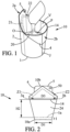
- the container 10 comprises a bottom wall 1 and is adapted to delimit an interior volume V above this bottom wall 1, by forming a side wall 2 connected (tightly) to the bottom wall 1.
- the container has an opening O, here a single opening which can be substantially as wide as the bottom 1a of the container 10 (at least as wide as a smaller dimension D2 of the bottom 1a, if necessary).
- Product P for example a food product, can be poured into the interior volume V via such an opening O, before a sealing step which is carried out by bringing together two protrusions 2a, 2b which are typically integrally formed with the side wall 2.
- the sealing obtained by fixing the two protrusions 2a, 2b against each other, makes it possible to obtain the closed state of the container 10.
- the top or top of this container 10 is thus of the closed type without a separate cover, as visible on the figures 2 And 3 .
- the container 10 can be made from two parts each made of a sheet material: one to constitute the bottom wall 1, the other to constitute the side wall 2.
- the walls 1 and 2 can be made from the same part obtained by cutting a sheet material. In other options, a larger number of coins can be used in order to obtain container 10.
- the fold LP is continuously curved and the bottom 1a may have a non-round section, for example oval with a large diameter D1 greater than the small diameter D2.
- the D2:D1 ratio can be less than or equal to 0.9.
- the external face of the tubular edge 1b can be fixed against a lower annular fixing zone of the side wall 2, called in the following first fixing part FP1.
- the lower end 10a of the container 10 can optionally extend lower than the bottom 1a.
- the top or upper end 10b of the container 10 may, in the closed configuration, include ends of the two protrusions 2a, 2b.
- the upper end 10b may include only one of the protrusions 2a, 2b, with in this case for example a lateral arrangement of the gripping portion associated with the protrusion of lower height.
- the side wall 2 is shaped like a tube, around a central axis is allowed here to produce the side wall 2 and the two protrusions 2a, 2b by a single part 200, of the type illustrated on the figure 5 or similar.
- a cut of a laminated or sheet material can for example be carried out to obtain the part 200, which is initially plane or flat before being shaped.
- the part 200 is flexible, based on a deformable material and for example of the cellulosic type.
- This cellulosic material can optionally form more than 90 or 95% of the average thickness of the container 10 (thickness which can correspond to the thickness of the side wall 2).
- the part 200 is laterally cut so as to include two side edges B1, B2.
- the two lateral edges B1, B2 diverge from one another as one approaches a zone or folding line of the folding protrusion 2b. This makes it possible to enlarge the opening O for better accessibility of the product P.
- a folding line is provided which is obtained by the addition of two deformation lines or initial striations S14a and S14b making it possible to obtain a folding line 14 of the type illustrated on the figure 1 .
- the lateral cut of the part 200 makes it possible to obtain an increasing profile of the perimeter of the side wall 2 (formed by this part 200), as one moves away from the bottom. 1a.
- the section of the container 10 is progressively larger.
- the first fixing part FP1 makes it possible to stiffen a first (lower) end of the side wall 2, by fixing it against the folded external annular face or edge 1b of the bottom wall 1. In this way the first end of the side wall 2 is stabilized and remains substantially constant/not deformed in section, without variation in geometry when passing from the closed configuration to the opening configuration of the container 10. Conversely, the second (top) end of the side wall 2 constitutes a annular end 20 of deformable section.
- the second fixing part FP2 which can be extended following a longitudinal extension as illustrated in the Figure 5 , makes it possible to maintain the tubular conformation of the side wall 2 while allowing a spacing between the two protrusions 2a, 2b which is accompanied by a rounding of the top of the side wall 2, in top view.
- the fixing/overlapping width corresponding to the second fixing part FP2 may be less than or equal to 10 mm, for example between 3 and 8 mm.
- the second fixing part FP2 defines an exterior fixing surface which is covered by a corresponding interior zone (on the rear side of the part 200 as illustrated in the Figure 5 , so that the side edge B1 and the associated side margin forming the fixing part FP2 will be hidden by the other side margin including the side edge B2.
- These side margins can be fixed one on top of the other, forming a liquid-tight barrier, for example by depositing an additional layer of coating, after fixing with overlap of edge B1 by edge B2.
- the cut sheet or part 200 thus has an overlapping region, with an overlap of the opposite edges B1, B2 of the part 200.
- the bottom wall 1 can possibly also already be joined from the inside against the first fixing part FP1 during the shaping of the side wall 2.
- a single piece 200 cut from a sheet can make it possible to produce the side wall 2, which extends from a lower edge 25 to an irregular upper cutting edge 26. While the lower edge 25 can make it possible to define an annular section corresponding to a base plane of the container 10 at its lower end 10a, in the tubular conformation of the part 200, the upper cutting edge 26 includes two or three vertices T1, T2, T3 which may be part of input portions 4, 5.
- junction line J at the level of one of the protrusions 2a, 2b, for example a longitudinal junction line passing through one of the gripping portions (here the gripping portion 5), makes it possible to extend the length of the fixing area.
- this junction line J corresponds to a maximum length of the side wall 2. This makes the container 10 more robust.
- One of the two protrusions 2a, 2b can be obtained by joining two protrusions 11, 12 initially formed in the part 200 at two opposite lateral ends, by overlapping and corresponding/coinciding, possibly at the same height level, the summits T2 and T3.
- the grip portion 4 is entirely included in the protrusion 12 and forms the vertex T3 of the part 200 before assembly, the vertex T2 not being as high as the vertex T3.
- the junction line J can stop before the input portion 4 or be offset relative to this input portion 4.
- junction line J can be provided and the examples shown are only given by way of illustration. Although two rectilinear edges B1, B2 are shown, wavy cutouts or with one or more hollowed-out regions may possibly be provided, without this preventing the side wall 2 from being shaped in a tubular manner.
- the part of the container 10 constituted by the part 200 may be devoid of a zone folded at 90° or more along a line or horizontal hinge zone (parallel to the bottom 1a).
- the container 10 can be adapted for various capacities of product P, which can be a fresh food product, for example a dairy product (yogurt-based depending on one option) and/or a compote, where appropriate a mixture of a solid product (such as Muesli, cereals, chocolate chips, etc.) in a fluid or semi-fluid base product.
- product P can be semi-liquid, solid, or contain at least partly a liquid.
- the product P is for example well suited to being consumed using a spoon and has the ability to fit the interior face F of the side wall 2.
- the interior face F of the side wall 2 and the upper face of the bottom wall 1 are contact faces made for example of a material and/or a film having low water permeability and approved for food contact.
- the material may be identical to that of the interior face F, with the possible exception of an optional layer used to obtain the sealing zone Z or Z1, Z2.
- a material and/or a covering film can be provided which optionally is not flammable.
- the oval shape of the bottom 1a can facilitate the formation of opposite panels 24, 25 constituting two main sub-parts of the side wall 2.
- the figure 2 shows, in front view, one of these panels 24 (front view in relation to the sealing zone or sealing plane SP).
- these panels 24, 25 are connected to each other via narrow sub-parts folded/curved each inwards and extending vertically between the bottom wall 1 and the level of the opening O.
- each narrow sub-part (narrow compared to the width of the panels 24, 25) has a geometric shape which is substantially triangular or frustoconical widening towards the bottom 1a. This shape is seen in side view in relation to the sealing plane SP.
- the two opposite narrow sub-parts are complementary to the panels 24, 25 and therefore complete the panels 24, 25 in the side wall 2.
- the panels 24, 25, visible in the closed configuration may have an identical or similar geometry, possibly with a difference in inclination relative to the vertical (more or less pronounced inclination, forming an angle more or less close to 90° relative to the bottom 1a which is here horizontal).
- the level H1 of filling with product P can vary slightly downwards by going from a closed state of the container 10 to an open state.
- the sealing zone Z can be substantially planar (with an ascending/vertical component), by defining a sealing plane SP, which typically implies, in this example, a coplanar extension of the protrusions 2a and 2b, at least for part.
- This has the effect of making the two main panels 24, 25 converge towards each other. in the closed configuration of the container 10, so that the folding line 14 separating the folding protrusion 2b from the first panel 24 can be adjacent to the second panel 25 in its connection zone with the protrusion 2a which extends this panel 25 upwards.
- the tightening effect between the panels 24, 25 pushes the product P upwards (this product P having a fluid or semi-fluid character), to a level H1 which is greater than the level H1' shown to the right of the Figure 7 .
- the interior face F1 of the protrusion 2a may include a self-adhesive layer or a contact fixing part, above the annular end 20 where the fold line 14 is defined.
- this layer is broken down into two regions 21, 22 which rise towards the upper end 10b, joining in a junction part close to the gripping portion 5.
- the fixing parts are distributed differently on the interior faces F1, F2 of the protrusions 2a, 2b. More generally, we understand that the arrangement of the sealing zone can be planned so that a region thereof is close to at least one of the gripping portions 4, 5.
- the sealing zone Z1, Z2 extends entirely above the annular end 20 where the fold line 14 is defined.
- the sealing zone Z1, Z2 here has an inverted “V” shape being broken down into a first sealing sub-zone Z1 and a second sealing zone which joins the first sealing sub-zone Z2 for continuity of the sealed connection contact made by the sealing zone Z1, Z2.
- the sealing zone can have any type of geometry to close (here from the top) the opening O. It can be advantageous for the sealing zone Z to locally have at least one upper cussing zone (intermediate between two parts descending sealing) and ends 3a, 3b approaching as close as possible to the upper level of the product P, for example by reaching the level of the opening O. It is understood that, in all cases, the sealing zone Z or Z1 , Z2 extends transversely to a central axis X of the tubular side wall 2.
- the sealing zone Z or Z1, Z2 extends continuously in the closed configuration between the two opposite ends 3a, 3b which are spaced horizontally from one another by a determined distance D3 greater than the largest characteristic dimension D1 of the bottom 1, as illustrated for example on the figure 2 .
- a joining edge of the side wall 2 present on the external face of this side wall 2 is covered with a plastic coating, for example deposited in the form of a jet/spray. This constitutes protection of the overlapping strip constituting the edge-to-edge junction J of the side wall 2 as shaped in a tubular manner, knowing that this junction J is located in a deformable part of the container 10.
- the material of the side wall 2 and the protrusions 2a, 2b is compatible with the formation of streaks, obtained for example by localized crushing of the fibrous and/or cellulose material integrated into the thickness of this material.
- One or more sets of grooves S14a, S14b, FL1, FL2, isolated groove or reliefs for assisting deformation and/or folding can facilitate obtaining, in the upper part of the side wall 2, a suitable geometry to the consumption of product P.
- grooves can be provided which each constitute a predetermined folding line.
- the grooves are provided exclusively in one of the two sub-parts or panels constituting the two opposite main faces of the container 10 in its closed configuration.
- An asymmetrical character of the container 10 can thus be obtained by placing horizontal grooves exclusively on the panel 24 connected to the protrusion 2b to be folded down to free and widen the opening O.
- the groove S14 placed in the plane of the opening O (this streak which may result from the combination of several streaks, for example the two streaks S14a, S14b shown on the figure 5 ) thus forms the fold line 14.
- the groove S14 can have a length substantially equal to half a perimeter of the annular end 20 bordering the opening O.
- any other local deformation or physicochemical treatment step can be used to form a folding line making it possible to form a folding protrusion 2b following a predetermined folding.
- folding lines parallel to the folding line 14, already present in the closed configuration of the container 10 are optionally formed using ridges FL1 which can be distributed on the folding protrusion 2b, while the other protrusion 2a may be smooth and free of fold lines. It is typically expected that these fold lines, here formed by ridges spaced at least 3 mm apart from each other, are shorter than the fold line 14, as visible in front view in the closed configuration.
- the folding of the flap formed by the protrusion 2b is done by quickly tilting the corresponding gripping/actuation portion (grasping portion 4 of the Figure 6 ) down.
- the reversal of orientation of the gripping portion 4 can be carried out before the protrusion 2b is folded back more than 45° around the line of folding 14, which is allowed using the small folding lines FL1.
- the end of the stroke can then consist of pulling the protrusion 2b downwards while continuing to fold and fold outwards the lowest part of the protrusion 2b, until obtaining the completely folded position of the type visible on the figure 1 , typically without significant widening of the opening O.
- the grooves FL2 can extend vertically on either side of the folding line 14 and contribute to assisting/helping the end of the stroke in the folding movement of the protrusion 2b, for example by avoiding the formation of an angle (s) blocking the movement of the flap.
- these FL2 grooves (here at least five or six in number) can provide a guiding effect, in order to round the side wall 2 more easily and avoiding the formation of a pronounced angle or V-shaped profile which would be visible in top view.
- the rounding of the fold line 14 can then be close or identical to the illustration of the figure 1 , avoiding forming a pronounced angle near the junction line J.
- a smooth surface is obtained which can make it possible to produce a print. More generally, any type of marking (possibly embossing) can be made on the surface without a fold line, such a surface being favorable to the visibility of information, for example information about the product P contained in the interior volume. V.
- the flattened appearance of the panel 25 also makes reading such information easy for a consumer observing the container 10 in a stored state on a shelf in a store or in a similar presentation situation.
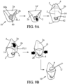
- FIGS. 9A and 9B show the way in which the container 10 can be manipulated, going from a compact configuration to a deployed configuration, then to an open configuration allowing the consumption of the product P contained in the interior volume V of the side wall 2.
- Fold lines FL1 can also be provided in this embodiment to facilitate the folding of the protrusion 2b with an arcuate conformation (curved outwards) compatible with a wide opening O of the container 10. This is an optional embodiment .
- the two protrusions 2a, 2b can be folded down on the same side against the external face of the side wall 2, in a modified closing configuration with all or part of the sealing zone folded down to extend below the level of an exterior folding line 14' here provided on the protrusion 2a.
- this configuration limits the height of the container 10.
- all or part of the sealing zone can be mobile in the state sealed with the two protrusions 2a, 2b, in particular when it is desired to minimize the height of the container 10 during transport and/or storage stages.
- the container 10 has a movable end (by pivoting or folding along the line 14') so that it can be folded down into a modified closed configuration.
- the user can release and/or grasp the movable end of the container 10 to straighten it, in order to move from the modified closed configuration to the closed configuration as shown on the figure 2 , 3 And 6 .
- the gripping portions 4, 5 are folded down with the protrusions 2a, 2b and thus protected from accidental opening manipulation.
- a fastening element may be provided, for example an adhesive pad 60, making it possible to maintain the modified closed configuration.
- the adhesive pad 60 is for example located on one fixing side and stuck laterally both on the side wall 2 and on an end part of the container including at least one of the gripping portions, here the gripping portion 5 of the protrusion 2a.
- the adhesive pad 60 includes a tab 60a or a similar pull tab constituting a gripping portion for detaching part of this pad and folding it downwards.
- the gripping portions 4 and 5 can have an operational configuration allowing the opening of the container 10.
- these gripping portions 4 and 5 extend upwards relative to the rest of the corresponding protrusions. 2a and 2b, which corresponds to the deployed closed configuration. More generally, we understand that in the closed configuration deployed/allowing the opening operation, we find the folding protrusion 2b in a position projecting upwards, from the folding line 14.
- the folding protrusion 2b can be folded outwards and come into contact with part of the adhesive face of the pad 60. Indeed, as this part of the adhesive face 61 has been turned outwards, it constitutes a support for fixing/maintaining the protrusion 2b in the folded position. In the example illustrated, the gripping portion 4 comes into contact with the adhesive face 61. It should be emphasized that this embodiment avoids completely detaching the pad 60, so that it does not constitute a loose and loseable part. In fact, there remains a fixed part 62, belonging to the pellet 60, which is not detached from the side wall 2.
- the bonding of the pellet 60 can be carried out with two different adhesion forces: stronger for the part 62 which is fixed and weaker for the part 61 which is peelable.
- the pad 60 is made in one piece and may consist of a multilayer sheet material, preferably without a metal layer.
- Obtaining a wide opening O is typically obtained in the same way already described with reference for example to the Figure 7 .
- Inward pressure by the user on the side wall 2, on either side of the folded protrusion 2b, makes it possible to enlarge the section of the opening O without raising the flap formed by the protrusion 2b .
- There consumption of the product P can then be done easily, for example by a utensil U such as a spoon, a fork or any other suitable utensil(s).
- the gripping portions 4, 5 are asymmetrical and one of them has an orifice 50, 50' facilitating the support of the container in store shelves or departments.
- the gripping portions 4, 5 are typically integrated into the protrusions 2a, 2b, without folding or change of direction, by projecting upwards/extending higher respectively with respect to an edge facing the other protrusion 2a or 2b.
- the upper end of the container 10 can then include these two gripping portions 4, 5 in the closed state.
- the gripping portions 4, 5 can be aligned in a plane SP which includes the sealing zone Z; Z1, Z2.
- the gripping portions 4, 5 can be provided for different shapes, symmetrical or non-symmetrical, can be provided for the gripping portions 4, 5.
- at least one of the gripping portions 4, 5 may not reach the upper end of the container 10 in the state closed and/or can form a tab placed externally to the SP sealing plane.
- Each grip portion may extend, vertically or obliquely, from a base line to a free upper end.
- Each base line of the grip portion 4 or 5 is then aligned with a delimiting edge of the other protrusion, delimitation edge of which exceeds the grip portion considered 4 or 5.
- this base line is elongated and exceeds 25 or 30 mm for each of the protrusions 4, 5, which makes these protrusions robust and easy to grip.
- They are optionally made from laminated cardboard or similar cellulose material which is sufficiently compressed and/or protected by a coating to be resistant to tearing, so that in practice they are impossible to tear accidentally.
- the protrusions 2a, 2b can each - or at least one of them - taper upwards in the closed configuration by being delimited by two delimiting edges 41, 42 or 51, 52. It is understood that the portion input 4, 5 can correspond to a region of the protrusion towards which the two delimiting edges 41, 42 or respectively 51, 52 converge.
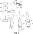
- Part 200 shown on the figure 5 can be obtained after a few steps including one or more cutting steps and processing steps making it possible to define the folding line 14 for folding the second folding protrusion 2b as well as other folding lines and/or weakening of material.
- a cutting step 51 is carried out, optionally at high speed, by a UC cutting tool in order to obtain pieces of sheet, here in a trapezoidal shape. It is understood that the part 200 can result from a cut made in one go or possibly broken down into an initial cut and a secondary cut of a piece of MF sheet material. In the example illustrated, for simplification, the protrusions have been omitted in the cutting step 51. However, it may be preferred to produce the outline of the two protrusions 2a, 2b from this initial cut made in step 51.
- this cut makes it possible to define the final lower edge 25, the two sides or lateral edges B1, B2 (in a general shape which is then close to a trapezoid) and also the two protrusions 2a, 2b.
- side edges B1, B2 are provided which move away from each other as we move away from the lower edge 25 and as we approach the level of the opening O
- This type of geometry of the side edges B1, B2 is advantageous for benefiting from an increased deformation effect at the level of the opening O.
- Each part 200 is then subjected to a series of treatments for shaping. For example, we can directly heat the strip portions formed in the lateral margins of each piece (margins including the edges B1, B2) and shape the part 200 into a sleeve. A rotating impression with frustoconical geometry can form a support so that the part 200 is wrapped around this imprint, so that they form a sleeve due to the overlap of the margins or side strip portions.
- This shaping step 52 can optionally combine heating and winding of the part 200.
- an edge protection step 53 is carried out in order to cover the edge(s) B1, B2, which are involved in forming the junction part J, with a coating which improves liquid tightness.
- the junction part J of the side wall 2 is permanently waterproof (taking into account the duration of transport/storage in, store then at the consumer's, in particular if it is a product to be kept at the fresh in a refrigerator).
- the part 200 is in its final conformation and already forms the side wall 2 provided with the protrusions 2a, 2b, without however being connected to the wall of background 1.
- the groups of horizontal streaks FL1 in the protrusion 2b and/or of streaks FL2 with a vertical component on either side of the streak S14 can be produced before step 52, respectively by pressure of at least an organ with imprints/reliefs.
- This type of orifice 50, 50' can facilitate the presentation and/or assembly (for example in a row) of a set of containers linked by a cord, necklace, carabiner or similar through connecting element each orifice of the containers of the same set.
- a sachet with contents that can be associated with the product P of the container can accompany the container 10 while also being attached to the necklace cord, carabiner or similar connecting element.
- bottom walls 1 are also designed from a roll of laminated material, preferably comprising a layer of paper or cardboard, for example the same material as the side wall 2.
- a shaping step 55 is carried out to fold the peripheral annular region of the corresponding part, so as to obtain the peripheral fold LP and create the border 1b, here surrounding an assembly member 18 with a frustoconical impression.
- connection between the wall elements 1 and 2 is for example carried out by a positioning step 61 with overlapping of the fixing part FP1 on the edge 1b, at the end of which the side wall 2 is maintained in a fixed predetermined position relative to the bottom wall 1.
- the figure 8 illustrates a final step 62 consisting of a hot fixing of the bottom wall 1.
- the container 10 ready to be filled can then be obtained by carrying out heating and possibly a pressure treatment, making it possible to attach the external face in a sealed manner. from the edge 1b inside the fixing part FP1.
- one or more sealing treatments can be carried out during step 62 or after step 62.
- junction J can be sealed in an assembled state of walls 1 and 2.
- the filling as shown on the figure 1 using any type of product dose pouring system P, can then be carried out, before the final closing step by creating the sealing zone Z or Z1, Z2.
- a container 10 whose side wall 2 is made in one piece
- a side face including attached parts can be provided. It is also possible to insert into the side wall 2 all kinds of elements facilitating handling, in particular one or more textured surfaces, ribs or other comparable surface characteristics, only on the side of the protrusion 2b or elsewhere.
- a ring may be provided (possibly with an elastic return effect) or a sleeve, for example configured to surround an upper part of the external face of the side wall 2.
- a rigid cup with a section comparable to the section of the opening O of the container 10 in an open state can also form a support for the container 10.
- Such a reusable ring or cup makes it possible, for example, to pass more easily the cross section of the upper end of the side wall 2 d 'a shape elongated oval (elongated towards the respective interstices N1, N2 formed between the two protrusions 2a, 2b) to a substantially circular shape which can facilitate the consumption of the product P, if necessary using a spoon.
- the ring or cup can be used to obtain the conformation shown on the right of the Figure 7 , typically after having folded down the protrusion 2b.
- the filling with product P can be carried out in various ways, possibly from the bottom before carrying out a definitive closing step from the bottom in certain variants, the filling can then be carried out opposite the opening a provided for recover/consume the product P.
Landscapes
- Engineering & Computer Science (AREA)
- Mechanical Engineering (AREA)
- Cartons (AREA)
- Packages (AREA)
Claims (16)
- Behälter (10), der zum Verpacken eines Produkts bestimmt ist, umfassend:- einen Boden (1a);- eine Seitenwand (2), die ein Innenvolumen (V) begrenzt, wobei sich die Seitenwand (2) ausgehend vom Boden (1a) nach oben bis zu einem ringförmigen Ende (20) erstreckt, welches eine Öffnung (O) für den Zugang zum Innenvolumen (V) begrenzt;wobei der Behälter (10) eine geschlossene Konfiguration hat und dadurch gekennzeichnet ist, dass er ferner zwei unterschiedliche Vorsprünge (2a, 2b) aufweist, um die geschlossene Konfiguration zu erhalten, wobei die beiden Vorsprünge (2a, 2b) gleichzeitig:- vom ringförmigen Ende (20) der Seitenwand (2) auf der dem Boden gegenüberliegenden Seite (1a) vorstehen, und- miteinander versiegelt sind, derart dass sie eine Versiegelungszone (Z; Z1, Z2) zum hermetischen Verschließen der Öffnung (O) bilden,wobei der Behälter (10) zwei Griffabschnitte (4, 5) aufweist, die über die beiden Vorsprünge (2a, 2b) verteilt sind, wobei jeder der beiden Griffabschnitte (4, 5) jenseits der Versiegelungszone (Z; Z1, Z2) angeordnet ist.
- Behälter nach Anspruch 1, wobei die beiden Griffabschnitte (4, 5) zueinander versetzt sind.
- Behälter nach Anspruch 1 oder 2, wobei wenigstens einer der beiden Vorsprünge ein Vorsprung (2b) ist, der einen nach außen gerichteten Umschlag umfasst.
- Behälter nach Anspruch 1 oder 2, wobei wenigstens einer der beiden Vorsprünge ein nach außen faltbarer Vorsprung (2b) ist,
und wobei die Öffnung (O) teilweise durch eine Faltlinie (14) zum Umfalten des faltbaren Vorsprungs (2b) begrenzt ist, bevorzugt derart, dass sich der faltbare Vorsprung (2b) von der Faltlinie (14) aus nach unten erstreckt. - Behälter nach Anspruch 4, wobei der faltbare Vorsprung (2b) verschiebbar ist zwischen:- einer ersten Position zum Verschließen des Behälters (10), indem er an der Innenseite des anderen der beiden Vorsprünge (2a) anliegt, wobei sich der faltbare Vorsprung (2b) von der Faltlinie (14), die parallel zum Boden (1a) verläuft, nach oben erstreckt, und- eine zweite Position, in der der Behälter (10) durch Falten des faltbaren Vorsprungs (2b) geöffnet wird, wobei diese Faltung nach außen gegenüber dem anderen Vorsprung (2a) erfolgt, der bevorzugt nach oben vorstehend bleibt.
- Behälter nach einem der vorhergehenden Ansprüche, wobei sich die Versiegelungszone quer zu einer Mittelachse (X) der Seitenwand (2) erstreckt, wobei sich die Versiegelungszone (Z; Z1, Z2) zwischen zwei gegenüberliegenden Enden (3a, 3b) erstreckt, die in der geschlossenen Konfiguration und in einem vertikal aufgerichteten Zustand der Seitenwand (2) horizontal zueinander um einen bestimmten Abstand (D3) beabstandet sind, der größer als die größte charakteristische Abmessung (D1) des sich horizontal erstreckenden Bodens (1a) ist.
- Behälter nach einem der vorhergehenden Ansprüche, wobei die Seitenwand (2) und die beiden Vorsprünge (2a, 2b) aus einem Stück gefertigt sind, bevorzugt einem Teil (200) in Form eines Zuschnitts aus einem Walz- oder Folienmaterial.
- Behälter nach Anspruch 7, wobei der Teil (200) auf einem verformbaren Material basiert, das ein Zellulosematerial enthält, und durch Überlappung von zwei Bandabschnitten geformt ist, die:- jeweils einen Seitenrand (B1, B2) der Seitenwand (2) einschließen; und- derart aneinander befestigt sind, dass sie eine flüssigkeitsdichte Barriere bilden.
- Behälter nach einem der vorhergehenden Ansprüche, wobei sich die Versiegelungszone (Z; Z1, Z2) linear oder zweidimensional erstreckt und eine Versiegelungsebene (SP) definiert, wobei die beiden Vorsprünge (2a, 2b) wenigstens teilweise aneinander anliegen, um sich parallel zu dieser Versiegelungsebene (SP) zu erstrecken.
- Behälter nach einem der vorhergehenden Ansprüche, wobei der Umfang der Seitenwand (2) mit zunehmendem Abstand vom Boden (1a) zunimmt.
- Behälter nach einem der vorhergehenden Ansprüche, wobei sich wenigstens einer der beiden Vorsprünge (2a, 2b) in der geschlossenen Konfiguration nach oben verjüngt und von zwei Begrenzungsrändern (41, 42; 51, 52) begrenzt ist und einen Griffabschnitt (4, 5) aufweist, der einer der beiden Griffabschnitte ist, zu dem die beiden Begrenzungsränder (41, 42; 51, 52) konvergieren.
- Behälter nach einem der vorhergehenden Ansprüche, wobei der Boden (1a) einen ovalen oder polygonalen, bevorzugt ovalen Außenrand aufweist, so dass er einen größeren Durchmesser (D1) oder maximalen Durchmesser und einen kleineren Durchmesser (D2) aufweist, wobei die Seitenwand (2) dazu ausgebildet ist, durch den Abstand zwischen den beiden Vorsprüngen (2a, 2b) in einem offenen Zustand des Behälters (10) eine Abmessung der Öffnung (O) entlang einer Aufweitungsrichtung parallel zur Richtung des kleinsten Durchmessers (D2) aufzuweiten.
- Behälter nach einem der vorhergehenden Ansprüche, wobei die Versiegelungszone (Z1, Z2) eine umgekehrte "V"-Form aufweist und/oder lokal wenigstens einen oberen Umschlagbereich aufweist.
- Behälter nach einem der vorhergehenden Ansprüche, wobei der gesamte oder ein Teil der Versiegelungszone (Z; Z1, Z2) Teil eines umgefalteten Endes des Behälters (10) in einer modifizierten geschlossenen Konfiguration ist, wobei sich die beiden Vorsprünge (2a, 2b) in einem umgefalteten Zustand auf einer gleichen seitlichen Seite des Behälters in der modifizierten geschlossenen Konfiguration befinden.
- Montageverfahren zum Erhalten des Behälters (10) nach einem der vorhergehenden Ansprüche, wobei das Innenvolumen (V) axial begrenzt wird zwischen einem Boden (1a), der einen unteren Teil des Behälters begrenzt, und einem axialen Verschlussteil, der eine Öffnung (O) für den Zugang von oben zum Innenvolumen (V) abdeckt, wobei das Verfahren nacheinander die folgenden Schritte umfasst, die im Wesentlichen umfassen:- Bereitstellen eines anfänglich ebenen Teils (200), das aus einem Zuschnitt eines Blattmaterials resultiert und zwei unterschiedliche Vorsprünge oder Ohren (2a, 2b) aufweist, die in Bezug auf einen Ausbildungsabschnitt einer Seitenwand (2) des Behälters (10) vorstehen,- ringförmiges Anpassen des Teils (200), um die Seitenwand (2) zu erhalten, die das Innenvolumen (V) begrenzt,- Verbinden einer Bodenwand (1) mit einem ersten Ende der Seitenwand (2), um den Boden (1a) zu bilden, wobei die Öffnung (O) an einem zweiten Ende gegenüber dem ersten Ende angeordnet ist, so dass sich die Seitenwand (2) im vertikal aufgerichteten Zustand des Behälters (10) vom Boden (1a) aufsteigend bis zu einem die Öffnung (O) begrenzenden ringförmigen Ende (20) erstreckt,- Füllen des Innenvolumens (V) mit Produkt (P) durch die Öffnung (O), und- hermetisches Verschließen der Öffnung (O), indem die beiden Vorsprünge (2a, 2b) einander angenähert und aneinander befestigt werden, so dass in einem geschlossenen Zustand des Behälters (10) die beiden Vorsprünge (2a, 2b) gleichzeitig gegenüber dem Boden (1a) von dem ringförmigen Ende (20) der Seitenwand (2) aus vorstehen und aufeinander versiegelt werden, wobei sie eine Versiegelungszone (Z; Z1, Z2) bilden, die es erlaubt, die Öffnung (O) hermetisch abzudichten,und wobei zwei Griffabschnitte (4, 5) über die beiden Vorsprünge (2a, 2b) verteilt sind, wobei jeder der beiden Griffabschnitte (4, 5) jenseits der Versiegelungszone (Z; Z1, Z2) angeordnet ist.
- Verwendung des Behälters (10) nach einem der Ansprüche 1 bis 14, wobei zum Öffnen des Behälters (10) die beiden Vorsprünge (2a, 2b) nacheinander:- in der geschlossenen Konfiguration gegenüber dem Boden (1a) aufgerichtet werden,- voneinander getrennt werden, indem die beiden Griffabschnitte (4, 5) auseinandergezogen werden, bis einer der beiden Vorsprünge (2b) selektiv nach außen gefaltet wird,wodurch der Behälter (10) geöffnet wird, indem eine zwischen den jeweiligen Innenflächen der beiden Vorsprünge (2a, 2b) hergestellte Siegelverbindung aufgebrochen wird, ohne einen der beiden Vorsprünge (2a, 2b) von der Seitenwand (2) zu trennen.
Applications Claiming Priority (2)
| Application Number | Priority Date | Filing Date | Title |
|---|---|---|---|
| FR1913727A FR3104142B1 (fr) | 2019-12-04 | 2019-12-04 | Recipient du type sans couvercle et methode d’assemblage du recipient |
| PCT/FR2020/052256 WO2021111080A1 (fr) | 2019-12-04 | 2020-12-03 | Recipient du type sans couvercle et methode d'assemblage du recipient |
Publications (2)
| Publication Number | Publication Date |
|---|---|
| EP4069596A1 EP4069596A1 (de) | 2022-10-12 |
| EP4069596B1 true EP4069596B1 (de) | 2023-11-15 |
Family
ID=70008685
Family Applications (1)
| Application Number | Title | Priority Date | Filing Date |
|---|---|---|---|
| EP20828036.2A Active EP4069596B1 (de) | 2019-12-04 | 2020-12-03 | Deckelloser behälter und verfahren zum zusammenbau des behälters |
Country Status (4)
| Country | Link |
|---|---|
| US (1) | US20230002103A1 (de) |
| EP (1) | EP4069596B1 (de) |
| FR (1) | FR3104142B1 (de) |
| WO (1) | WO2021111080A1 (de) |
Family Cites Families (24)
| Publication number | Priority date | Publication date | Assignee | Title |
|---|---|---|---|---|
| US2074824A (en) * | 1935-03-16 | 1937-03-23 | Karlsson-Ygger Albert | Container |
| DE1052305B (de) * | 1955-02-15 | 1959-03-05 | Jagenberg Werke Ag | Fluessigkeitsdichter Papier- oder Kartonbehaelter mit Faltverschluss und Ausgusstuelle |
| US2949370A (en) * | 1957-09-23 | 1960-08-16 | Ree Ceel Corp | Package |
| US3419137A (en) * | 1967-11-14 | 1968-12-31 | Bard Inc C R | Closed-end peel package |
| US4332577A (en) * | 1978-10-13 | 1982-06-01 | Novus Corp. N.V. | Packaging |
| US5018646A (en) * | 1988-11-23 | 1991-05-28 | S. C. Johnson & Son, Inc. | Squeezable fluid container |
| US5352466A (en) * | 1991-10-15 | 1994-10-04 | Kraft General Foods, Inc. | Tabbed easy-open brick coffee package |
| GB9217932D0 (en) | 1992-08-22 | 1992-10-07 | Weston Terence E | Snap action closure |
| US5611627A (en) * | 1995-02-23 | 1997-03-18 | Tenneco Packaging | Easy open thermoplastic bag |
| US5655707A (en) * | 1996-05-30 | 1997-08-12 | International Paper | Paperboard carton with cohesive closure |
| US6200028B1 (en) * | 1997-09-22 | 2001-03-13 | Technical Developers, Inc. | Convertible package and bowl type container |
| US5960987A (en) * | 1998-04-16 | 1999-10-05 | Flip Cup Company, Llc | Self sealing drinking dispenser |
| ES1044375Y (es) | 1999-10-14 | 2000-10-16 | Polarcup S A | Vaso desechable mejorado. |
| US20060188180A1 (en) * | 2005-02-24 | 2006-08-24 | Hirofusa Otsubo | Plastic bags with gripping tabs |
| US20070102317A1 (en) * | 2005-11-08 | 2007-05-10 | Colgate-Palmolive Company | Easy open thermoformed package |
| US20070202284A1 (en) * | 2006-02-24 | 2007-08-30 | The Quaker Oats Company | Cost-effective, sanitary, high-barrier microwavable wrapper |
| US9751655B2 (en) * | 2009-06-12 | 2017-09-05 | Compleat Llc | Vessel with folded dam |
| US8678651B2 (en) * | 2010-07-19 | 2014-03-25 | S.C. Johnson & Son, Inc. | Disposable storage bags |
| US20140193102A1 (en) * | 2011-08-31 | 2014-07-10 | Angela Weir | Easy Open Storage Bag Container |
| US8746545B2 (en) * | 2012-08-09 | 2014-06-10 | Russell E. Houck | Drink cup for road running races |
| US9114914B2 (en) * | 2012-09-28 | 2015-08-25 | S.C. Johnson & Son, Inc. | Storage bag with textured area on lips to facilitate closing process |
| US20200102111A1 (en) * | 2018-09-28 | 2020-04-02 | Robin Thurgood | Recyclable Cup |
| WO2021073599A1 (en) * | 2019-10-17 | 2021-04-22 | Addless Design Limited | A cup, a blank for a cup and a method of forming a cup |
| WO2021117158A1 (ja) * | 2019-12-11 | 2021-06-17 | 北越パッケージ株式会社 | 紙製容器 |
-
2019
- 2019-12-04 FR FR1913727A patent/FR3104142B1/fr active Active
-
2020
- 2020-12-03 EP EP20828036.2A patent/EP4069596B1/de active Active
- 2020-12-03 WO PCT/FR2020/052256 patent/WO2021111080A1/fr not_active Ceased
- 2020-12-03 US US17/782,455 patent/US20230002103A1/en not_active Abandoned
Also Published As
| Publication number | Publication date |
|---|---|
| FR3104142B1 (fr) | 2021-12-17 |
| WO2021111080A1 (fr) | 2021-06-10 |
| FR3104142A1 (fr) | 2021-06-11 |
| EP4069596A1 (de) | 2022-10-12 |
| US20230002103A1 (en) | 2023-01-05 |
Similar Documents
| Publication | Publication Date | Title |
|---|---|---|
| EP2259972B1 (de) | Kartonvorformensatz, schachtel und verfahren zur herstellung einer schachtel mit solchen vorformen | |
| EP2221258B1 (de) | Behälter, insbesondere für feste oder pastöse Produkte, Verfahren zu dessen Herstellung und Verpackung enthaltend diesen Behälter und einen zusätzlichen Behälter | |
| FR2772011A1 (fr) | Etui pour produits, et article obtenu | |
| FR1278952A (fr) | Perfectionnements aux récipients d'emballage et à leurs procédés de fabrication | |
| CA2780296C (fr) | Emballage d'un produit alimentaire portionnable | |
| EP0290356B1 (de) | Faltbarer Trinkbecher mit Originalitätsvorrichtung | |
| FR2772009A1 (fr) | Etui pour produits, et article obtenu | |
| EP4069596B1 (de) | Deckelloser behälter und verfahren zum zusammenbau des behälters | |
| FR3002209A1 (fr) | Emballage, notamment pour un produit alimentaire, et contenant correspondant | |
| FR3013039A1 (fr) | Emballage de carton decoupable integrant un coupon detachable | |
| FR2966447A1 (fr) | Ensemble de conditionnement de produits a texture pateuse ou semi-liquide, et procede de fabrication correspondant | |
| WO2017182737A1 (fr) | Sac de transport d'article | |
| EP3144238B1 (de) | Verpackung und zuschnitt für eine verpackung mit einer verbesserten öffnungsvorrichtung | |
| EP2354031B1 (de) | Behälter mit Deckel | |
| EP1549512B1 (de) | Mehrzweckdeckel zum schliessen von behältern, insbesondere farbbehältern | |
| FR2614873A1 (fr) | Gobelet pliable avec dispositif d'inviolabilite | |
| EP2544966B1 (de) | Portionierbare verpackung für ein lebensmittelprodukt | |
| FR2986785A1 (fr) | Ensemble de conditionnement de produits a texture pateuse ou semi-liquide. | |
| WO2013001197A1 (fr) | Ensemble alimentaire et son procédé de fabrication et gabarit pour la mise en œuvre dudit procédé | |
| WO2017211568A1 (fr) | Procede de fabrication d'un gobelet comportant un flanc pince et colle dans sa partie superieure, et gobelet issue du procede | |
| FR2943639A1 (fr) | Boite de section triangulaire pour le conditionnement et la distribution de produits et flan permettant de realiser une telle boite. | |
| FR3065148A1 (fr) | Ensemble comprenant un produit de boulangerie et un recipient dudit produit et procede de conditionnement d’un produit de boulangerie pour l’obtention d’un tel ensemble | |
| WO1995030600A1 (fr) | Dispositif d'ouverture facile et controlee d'un sachet souple et sachet ainsi obtenu | |
| FR2845311A1 (fr) | Gobelet et son procede de fabrication | |
| FR2822453A1 (fr) | Boite d'emballage perfectionnee a couvercle articule et a temoin d'ouverture, notamment pour des oeufs |
Legal Events
| Date | Code | Title | Description |
|---|---|---|---|
| STAA | Information on the status of an ep patent application or granted ep patent |
Free format text: STATUS: UNKNOWN |
|
| STAA | Information on the status of an ep patent application or granted ep patent |
Free format text: STATUS: THE INTERNATIONAL PUBLICATION HAS BEEN MADE |
|
| PUAI | Public reference made under article 153(3) epc to a published international application that has entered the european phase |
Free format text: ORIGINAL CODE: 0009012 |
|
| STAA | Information on the status of an ep patent application or granted ep patent |
Free format text: STATUS: REQUEST FOR EXAMINATION WAS MADE |
|
| 17P | Request for examination filed |
Effective date: 20220608 |
|
| AK | Designated contracting states |
Kind code of ref document: A1 Designated state(s): AL AT BE BG CH CY CZ DE DK EE ES FI FR GB GR HR HU IE IS IT LI LT LU LV MC MK MT NL NO PL PT RO RS SE SI SK SM TR |
|
| DAV | Request for validation of the european patent (deleted) | ||
| DAX | Request for extension of the european patent (deleted) | ||
| GRAP | Despatch of communication of intention to grant a patent |
Free format text: ORIGINAL CODE: EPIDOSNIGR1 |
|
| STAA | Information on the status of an ep patent application or granted ep patent |
Free format text: STATUS: GRANT OF PATENT IS INTENDED |
|
| INTG | Intention to grant announced |
Effective date: 20230612 |
|
| GRAS | Grant fee paid |
Free format text: ORIGINAL CODE: EPIDOSNIGR3 |
|
| GRAA | (expected) grant |
Free format text: ORIGINAL CODE: 0009210 |
|
| STAA | Information on the status of an ep patent application or granted ep patent |
Free format text: STATUS: THE PATENT HAS BEEN GRANTED |
|
| AK | Designated contracting states |
Kind code of ref document: B1 Designated state(s): AL AT BE BG CH CY CZ DE DK EE ES FI FR GB GR HR HU IE IS IT LI LT LU LV MC MK MT NL NO PL PT RO RS SE SI SK SM TR |
|
| REG | Reference to a national code |
Ref country code: CH Ref legal event code: EP Ref country code: GB Ref legal event code: FG4D Free format text: NOT ENGLISH |
|
| REG | Reference to a national code |
Ref country code: DE Ref legal event code: R096 Ref document number: 602020021236 Country of ref document: DE |
|
| REG | Reference to a national code |
Ref country code: IE Ref legal event code: FG4D Free format text: LANGUAGE OF EP DOCUMENT: FRENCH |
|
| REG | Reference to a national code |
Ref country code: LT Ref legal event code: MG9D |
|
| REG | Reference to a national code |
Ref country code: NL Ref legal event code: MP Effective date: 20231115 |
|
| PG25 | Lapsed in a contracting state [announced via postgrant information from national office to epo] |
Ref country code: GR Free format text: LAPSE BECAUSE OF FAILURE TO SUBMIT A TRANSLATION OF THE DESCRIPTION OR TO PAY THE FEE WITHIN THE PRESCRIBED TIME-LIMIT Effective date: 20240216 |
|
| PG25 | Lapsed in a contracting state [announced via postgrant information from national office to epo] |
Ref country code: IS Free format text: LAPSE BECAUSE OF FAILURE TO SUBMIT A TRANSLATION OF THE DESCRIPTION OR TO PAY THE FEE WITHIN THE PRESCRIBED TIME-LIMIT Effective date: 20240315 |
|
| PG25 | Lapsed in a contracting state [announced via postgrant information from national office to epo] |
Ref country code: LT Free format text: LAPSE BECAUSE OF FAILURE TO SUBMIT A TRANSLATION OF THE DESCRIPTION OR TO PAY THE FEE WITHIN THE PRESCRIBED TIME-LIMIT Effective date: 20231115 |
|
| REG | Reference to a national code |
Ref country code: AT Ref legal event code: MK05 Ref document number: 1631566 Country of ref document: AT Kind code of ref document: T Effective date: 20231115 |
|
| PG25 | Lapsed in a contracting state [announced via postgrant information from national office to epo] |
Ref country code: NL Free format text: LAPSE BECAUSE OF FAILURE TO SUBMIT A TRANSLATION OF THE DESCRIPTION OR TO PAY THE FEE WITHIN THE PRESCRIBED TIME-LIMIT Effective date: 20231115 |
|
| PG25 | Lapsed in a contracting state [announced via postgrant information from national office to epo] |
Ref country code: AT Free format text: LAPSE BECAUSE OF FAILURE TO SUBMIT A TRANSLATION OF THE DESCRIPTION OR TO PAY THE FEE WITHIN THE PRESCRIBED TIME-LIMIT Effective date: 20231115 |
|
| PG25 | Lapsed in a contracting state [announced via postgrant information from national office to epo] |
Ref country code: ES Free format text: LAPSE BECAUSE OF FAILURE TO SUBMIT A TRANSLATION OF THE DESCRIPTION OR TO PAY THE FEE WITHIN THE PRESCRIBED TIME-LIMIT Effective date: 20231115 |
|
| PG25 | Lapsed in a contracting state [announced via postgrant information from national office to epo] |
Ref country code: NL Free format text: LAPSE BECAUSE OF FAILURE TO SUBMIT A TRANSLATION OF THE DESCRIPTION OR TO PAY THE FEE WITHIN THE PRESCRIBED TIME-LIMIT Effective date: 20231115 Ref country code: LT Free format text: LAPSE BECAUSE OF FAILURE TO SUBMIT A TRANSLATION OF THE DESCRIPTION OR TO PAY THE FEE WITHIN THE PRESCRIBED TIME-LIMIT Effective date: 20231115 Ref country code: IS Free format text: LAPSE BECAUSE OF FAILURE TO SUBMIT A TRANSLATION OF THE DESCRIPTION OR TO PAY THE FEE WITHIN THE PRESCRIBED TIME-LIMIT Effective date: 20240315 Ref country code: GR Free format text: LAPSE BECAUSE OF FAILURE TO SUBMIT A TRANSLATION OF THE DESCRIPTION OR TO PAY THE FEE WITHIN THE PRESCRIBED TIME-LIMIT Effective date: 20240216 Ref country code: ES Free format text: LAPSE BECAUSE OF FAILURE TO SUBMIT A TRANSLATION OF THE DESCRIPTION OR TO PAY THE FEE WITHIN THE PRESCRIBED TIME-LIMIT Effective date: 20231115 Ref country code: BG Free format text: LAPSE BECAUSE OF FAILURE TO SUBMIT A TRANSLATION OF THE DESCRIPTION OR TO PAY THE FEE WITHIN THE PRESCRIBED TIME-LIMIT Effective date: 20240215 Ref country code: AT Free format text: LAPSE BECAUSE OF FAILURE TO SUBMIT A TRANSLATION OF THE DESCRIPTION OR TO PAY THE FEE WITHIN THE PRESCRIBED TIME-LIMIT Effective date: 20231115 Ref country code: PT Free format text: LAPSE BECAUSE OF FAILURE TO SUBMIT A TRANSLATION OF THE DESCRIPTION OR TO PAY THE FEE WITHIN THE PRESCRIBED TIME-LIMIT Effective date: 20240315 |
|
| PG25 | Lapsed in a contracting state [announced via postgrant information from national office to epo] |
Ref country code: SE Free format text: LAPSE BECAUSE OF FAILURE TO SUBMIT A TRANSLATION OF THE DESCRIPTION OR TO PAY THE FEE WITHIN THE PRESCRIBED TIME-LIMIT Effective date: 20231115 Ref country code: RS Free format text: LAPSE BECAUSE OF FAILURE TO SUBMIT A TRANSLATION OF THE DESCRIPTION OR TO PAY THE FEE WITHIN THE PRESCRIBED TIME-LIMIT Effective date: 20231115 Ref country code: PL Free format text: LAPSE BECAUSE OF FAILURE TO SUBMIT A TRANSLATION OF THE DESCRIPTION OR TO PAY THE FEE WITHIN THE PRESCRIBED TIME-LIMIT Effective date: 20231115 Ref country code: NO Free format text: LAPSE BECAUSE OF FAILURE TO SUBMIT A TRANSLATION OF THE DESCRIPTION OR TO PAY THE FEE WITHIN THE PRESCRIBED TIME-LIMIT Effective date: 20240215 Ref country code: LV Free format text: LAPSE BECAUSE OF FAILURE TO SUBMIT A TRANSLATION OF THE DESCRIPTION OR TO PAY THE FEE WITHIN THE PRESCRIBED TIME-LIMIT Effective date: 20231115 Ref country code: HR Free format text: LAPSE BECAUSE OF FAILURE TO SUBMIT A TRANSLATION OF THE DESCRIPTION OR TO PAY THE FEE WITHIN THE PRESCRIBED TIME-LIMIT Effective date: 20231115 |
|
| PG25 | Lapsed in a contracting state [announced via postgrant information from national office to epo] |
Ref country code: DK Free format text: LAPSE BECAUSE OF FAILURE TO SUBMIT A TRANSLATION OF THE DESCRIPTION OR TO PAY THE FEE WITHIN THE PRESCRIBED TIME-LIMIT Effective date: 20231115 |
|
| PG25 | Lapsed in a contracting state [announced via postgrant information from national office to epo] |
Ref country code: CZ Free format text: LAPSE BECAUSE OF FAILURE TO SUBMIT A TRANSLATION OF THE DESCRIPTION OR TO PAY THE FEE WITHIN THE PRESCRIBED TIME-LIMIT Effective date: 20231115 |
|
| PG25 | Lapsed in a contracting state [announced via postgrant information from national office to epo] |
Ref country code: SK Free format text: LAPSE BECAUSE OF FAILURE TO SUBMIT A TRANSLATION OF THE DESCRIPTION OR TO PAY THE FEE WITHIN THE PRESCRIBED TIME-LIMIT Effective date: 20231115 |
|
| PG25 | Lapsed in a contracting state [announced via postgrant information from national office to epo] |
Ref country code: SM Free format text: LAPSE BECAUSE OF FAILURE TO SUBMIT A TRANSLATION OF THE DESCRIPTION OR TO PAY THE FEE WITHIN THE PRESCRIBED TIME-LIMIT Effective date: 20231115 Ref country code: SK Free format text: LAPSE BECAUSE OF FAILURE TO SUBMIT A TRANSLATION OF THE DESCRIPTION OR TO PAY THE FEE WITHIN THE PRESCRIBED TIME-LIMIT Effective date: 20231115 Ref country code: RO Free format text: LAPSE BECAUSE OF FAILURE TO SUBMIT A TRANSLATION OF THE DESCRIPTION OR TO PAY THE FEE WITHIN THE PRESCRIBED TIME-LIMIT Effective date: 20231115 Ref country code: IT Free format text: LAPSE BECAUSE OF FAILURE TO SUBMIT A TRANSLATION OF THE DESCRIPTION OR TO PAY THE FEE WITHIN THE PRESCRIBED TIME-LIMIT Effective date: 20231115 Ref country code: EE Free format text: LAPSE BECAUSE OF FAILURE TO SUBMIT A TRANSLATION OF THE DESCRIPTION OR TO PAY THE FEE WITHIN THE PRESCRIBED TIME-LIMIT Effective date: 20231115 Ref country code: DK Free format text: LAPSE BECAUSE OF FAILURE TO SUBMIT A TRANSLATION OF THE DESCRIPTION OR TO PAY THE FEE WITHIN THE PRESCRIBED TIME-LIMIT Effective date: 20231115 Ref country code: CZ Free format text: LAPSE BECAUSE OF FAILURE TO SUBMIT A TRANSLATION OF THE DESCRIPTION OR TO PAY THE FEE WITHIN THE PRESCRIBED TIME-LIMIT Effective date: 20231115 |
|
| REG | Reference to a national code |
Ref country code: DE Ref legal event code: R097 Ref document number: 602020021236 Country of ref document: DE |
|
| PG25 | Lapsed in a contracting state [announced via postgrant information from national office to epo] |
Ref country code: LU Free format text: LAPSE BECAUSE OF NON-PAYMENT OF DUE FEES Effective date: 20231203 |
|
| PG25 | Lapsed in a contracting state [announced via postgrant information from national office to epo] |
Ref country code: MC Free format text: LAPSE BECAUSE OF FAILURE TO SUBMIT A TRANSLATION OF THE DESCRIPTION OR TO PAY THE FEE WITHIN THE PRESCRIBED TIME-LIMIT Effective date: 20231115 |
|
| REG | Reference to a national code |
Ref country code: BE Ref legal event code: MM Effective date: 20231231 |
|
| PG25 | Lapsed in a contracting state [announced via postgrant information from national office to epo] |
Ref country code: MC Free format text: LAPSE BECAUSE OF FAILURE TO SUBMIT A TRANSLATION OF THE DESCRIPTION OR TO PAY THE FEE WITHIN THE PRESCRIBED TIME-LIMIT Effective date: 20231115 Ref country code: LU Free format text: LAPSE BECAUSE OF NON-PAYMENT OF DUE FEES Effective date: 20231203 |
|
| PLBE | No opposition filed within time limit |
Free format text: ORIGINAL CODE: 0009261 |
|
| STAA | Information on the status of an ep patent application or granted ep patent |
Free format text: STATUS: NO OPPOSITION FILED WITHIN TIME LIMIT |
|
| REG | Reference to a national code |
Ref country code: IE Ref legal event code: MM4A |
|
| PG25 | Lapsed in a contracting state [announced via postgrant information from national office to epo] |
Ref country code: IE Free format text: LAPSE BECAUSE OF NON-PAYMENT OF DUE FEES Effective date: 20231203 |
|
| PG25 | Lapsed in a contracting state [announced via postgrant information from national office to epo] |
Ref country code: BE Free format text: LAPSE BECAUSE OF NON-PAYMENT OF DUE FEES Effective date: 20231231 |
|
| 26N | No opposition filed |
Effective date: 20240819 |
|
| PG25 | Lapsed in a contracting state [announced via postgrant information from national office to epo] |
Ref country code: SI Free format text: LAPSE BECAUSE OF FAILURE TO SUBMIT A TRANSLATION OF THE DESCRIPTION OR TO PAY THE FEE WITHIN THE PRESCRIBED TIME-LIMIT Effective date: 20231115 |
|
| PG25 | Lapsed in a contracting state [announced via postgrant information from national office to epo] |
Ref country code: SI Free format text: LAPSE BECAUSE OF FAILURE TO SUBMIT A TRANSLATION OF THE DESCRIPTION OR TO PAY THE FEE WITHIN THE PRESCRIBED TIME-LIMIT Effective date: 20231115 Ref country code: IE Free format text: LAPSE BECAUSE OF NON-PAYMENT OF DUE FEES Effective date: 20231203 Ref country code: BE Free format text: LAPSE BECAUSE OF NON-PAYMENT OF DUE FEES Effective date: 20231231 |
|
| REG | Reference to a national code |
Ref country code: DE Ref legal event code: R082 Ref document number: 602020021236 Country of ref document: DE Representative=s name: PLASSERAUD IP GMBH, DE |
|
| PGFP | Annual fee paid to national office [announced via postgrant information from national office to epo] |
Ref country code: CH Payment date: 20250101 Year of fee payment: 5 |
|
| PG25 | Lapsed in a contracting state [announced via postgrant information from national office to epo] |
Ref country code: FI Free format text: LAPSE BECAUSE OF FAILURE TO SUBMIT A TRANSLATION OF THE DESCRIPTION OR TO PAY THE FEE WITHIN THE PRESCRIBED TIME-LIMIT Effective date: 20231115 |
|
| PG25 | Lapsed in a contracting state [announced via postgrant information from national office to epo] |
Ref country code: CY Free format text: LAPSE BECAUSE OF FAILURE TO SUBMIT A TRANSLATION OF THE DESCRIPTION OR TO PAY THE FEE WITHIN THE PRESCRIBED TIME-LIMIT; INVALID AB INITIO Effective date: 20201203 |
|
| PG25 | Lapsed in a contracting state [announced via postgrant information from national office to epo] |
Ref country code: HU Free format text: LAPSE BECAUSE OF FAILURE TO SUBMIT A TRANSLATION OF THE DESCRIPTION OR TO PAY THE FEE WITHIN THE PRESCRIBED TIME-LIMIT; INVALID AB INITIO Effective date: 20201203 |
|
| PG25 | Lapsed in a contracting state [announced via postgrant information from national office to epo] |
Ref country code: TR Free format text: LAPSE BECAUSE OF FAILURE TO SUBMIT A TRANSLATION OF THE DESCRIPTION OR TO PAY THE FEE WITHIN THE PRESCRIBED TIME-LIMIT Effective date: 20231115 |
|
| REG | Reference to a national code |
Ref country code: CH Ref legal event code: U11 Free format text: ST27 STATUS EVENT CODE: U-0-0-U10-U11 (AS PROVIDED BY THE NATIONAL OFFICE) Effective date: 20260101 |
|
| PGFP | Annual fee paid to national office [announced via postgrant information from national office to epo] |
Ref country code: GB Payment date: 20251229 Year of fee payment: 6 |
|
| PGFP | Annual fee paid to national office [announced via postgrant information from national office to epo] |
Ref country code: FR Payment date: 20251121 Year of fee payment: 6 |
|
| PGFP | Annual fee paid to national office [announced via postgrant information from national office to epo] |
Ref country code: DE Payment date: 20251231 Year of fee payment: 6 |