EP4068433A1 - Membranelektrodenanordnung mit einer gasdiffusionsschicht und verfahren zur herstellung einer membranelektrodenanordnung mit einer gasdiffusionsschicht - Google Patents
Membranelektrodenanordnung mit einer gasdiffusionsschicht und verfahren zur herstellung einer membranelektrodenanordnung mit einer gasdiffusionsschicht Download PDFInfo
- Publication number
- EP4068433A1 EP4068433A1 EP21216846.2A EP21216846A EP4068433A1 EP 4068433 A1 EP4068433 A1 EP 4068433A1 EP 21216846 A EP21216846 A EP 21216846A EP 4068433 A1 EP4068433 A1 EP 4068433A1
- Authority
- EP
- European Patent Office
- Prior art keywords
- gas diffusion
- diffusion layer
- electrode assembly
- layer
- membrane electrode
- Prior art date
- Legal status (The legal status is an assumption and is not a legal conclusion. Google has not performed a legal analysis and makes no representation as to the accuracy of the status listed.)
- Granted
Links
Images


Classifications
-
- H—ELECTRICITY
- H01—ELECTRIC ELEMENTS
- H01M—PROCESSES OR MEANS, e.g. BATTERIES, FOR THE DIRECT CONVERSION OF CHEMICAL ENERGY INTO ELECTRICAL ENERGY
- H01M8/00—Fuel cells; Manufacture thereof
- H01M8/10—Fuel cells with solid electrolytes
- H01M8/1004—Fuel cells with solid electrolytes characterised by membrane-electrode assemblies [MEA]
-
- H—ELECTRICITY
- H01—ELECTRIC ELEMENTS
- H01M—PROCESSES OR MEANS, e.g. BATTERIES, FOR THE DIRECT CONVERSION OF CHEMICAL ENERGY INTO ELECTRICAL ENERGY
- H01M4/00—Electrodes
- H01M4/86—Inert electrodes with catalytic activity, e.g. for fuel cells
- H01M4/8605—Porous electrodes
-
- H—ELECTRICITY
- H01—ELECTRIC ELEMENTS
- H01M—PROCESSES OR MEANS, e.g. BATTERIES, FOR THE DIRECT CONVERSION OF CHEMICAL ENERGY INTO ELECTRICAL ENERGY
- H01M4/00—Electrodes
- H01M4/86—Inert electrodes with catalytic activity, e.g. for fuel cells
- H01M4/88—Processes of manufacture
- H01M4/8803—Supports for the deposition of the catalytic active composition
- H01M4/8807—Gas diffusion layers
-
- H—ELECTRICITY
- H01—ELECTRIC ELEMENTS
- H01M—PROCESSES OR MEANS, e.g. BATTERIES, FOR THE DIRECT CONVERSION OF CHEMICAL ENERGY INTO ELECTRICAL ENERGY
- H01M4/00—Electrodes
- H01M4/86—Inert electrodes with catalytic activity, e.g. for fuel cells
- H01M4/88—Processes of manufacture
- H01M4/8803—Supports for the deposition of the catalytic active composition
- H01M4/881—Electrolytic membranes
-
- H—ELECTRICITY
- H01—ELECTRIC ELEMENTS
- H01M—PROCESSES OR MEANS, e.g. BATTERIES, FOR THE DIRECT CONVERSION OF CHEMICAL ENERGY INTO ELECTRICAL ENERGY
- H01M8/00—Fuel cells; Manufacture thereof
- H01M8/02—Details
- H01M8/0202—Collectors; Separators, e.g. bipolar separators; Interconnectors
- H01M8/023—Porous and characterised by the material
-
- H—ELECTRICITY
- H01—ELECTRIC ELEMENTS
- H01M—PROCESSES OR MEANS, e.g. BATTERIES, FOR THE DIRECT CONVERSION OF CHEMICAL ENERGY INTO ELECTRICAL ENERGY
- H01M8/00—Fuel cells; Manufacture thereof
- H01M8/02—Details
- H01M8/0271—Sealing or supporting means around electrodes, matrices or membranes
- H01M8/0273—Sealing or supporting means around electrodes, matrices or membranes with sealing or supporting means in the form of a frame
-
- H—ELECTRICITY
- H01—ELECTRIC ELEMENTS
- H01M—PROCESSES OR MEANS, e.g. BATTERIES, FOR THE DIRECT CONVERSION OF CHEMICAL ENERGY INTO ELECTRICAL ENERGY
- H01M8/00—Fuel cells; Manufacture thereof
- H01M8/10—Fuel cells with solid electrolytes
- H01M2008/1095—Fuel cells with polymeric electrolytes
-
- Y—GENERAL TAGGING OF NEW TECHNOLOGICAL DEVELOPMENTS; GENERAL TAGGING OF CROSS-SECTIONAL TECHNOLOGIES SPANNING OVER SEVERAL SECTIONS OF THE IPC; TECHNICAL SUBJECTS COVERED BY FORMER USPC CROSS-REFERENCE ART COLLECTIONS [XRACs] AND DIGESTS
- Y02—TECHNOLOGIES OR APPLICATIONS FOR MITIGATION OR ADAPTATION AGAINST CLIMATE CHANGE
- Y02E—REDUCTION OF GREENHOUSE GAS [GHG] EMISSIONS, RELATED TO ENERGY GENERATION, TRANSMISSION OR DISTRIBUTION
- Y02E60/00—Enabling technologies; Technologies with a potential or indirect contribution to GHG emissions mitigation
- Y02E60/30—Hydrogen technology
- Y02E60/50—Fuel cells
-
- Y—GENERAL TAGGING OF NEW TECHNOLOGICAL DEVELOPMENTS; GENERAL TAGGING OF CROSS-SECTIONAL TECHNOLOGIES SPANNING OVER SEVERAL SECTIONS OF THE IPC; TECHNICAL SUBJECTS COVERED BY FORMER USPC CROSS-REFERENCE ART COLLECTIONS [XRACs] AND DIGESTS
- Y02—TECHNOLOGIES OR APPLICATIONS FOR MITIGATION OR ADAPTATION AGAINST CLIMATE CHANGE
- Y02P—CLIMATE CHANGE MITIGATION TECHNOLOGIES IN THE PRODUCTION OR PROCESSING OF GOODS
- Y02P70/00—Climate change mitigation technologies in the production process for final industrial or consumer products
- Y02P70/50—Manufacturing or production processes characterised by the final manufactured product
Definitions
- the present invention relates to a membrane electrode assembly with gas diffusion layer and a manufacturing method for the membrane electrode assembly with gas diffusion layer.
- a fuel cell such as a polymer electrolyte fuel cell generates power and heat simultaneously by electrochemically causing reaction at a gas diffusion layer with a catalyst layer made of a material such as platinum between a fuel gas containing hydrogen and an oxidizing gas containing oxygen such as air.
- a cell of a polymer electrolyte fuel cell has a five-layer membrane electrode assembly (5-layer MEA).
- the 5-layer MEA has a structure containing a 3-layer membrane electrode assembly (3-layer MEA) including an ion-permeable electrolyte membrane, and an anode-side catalyst layer and a cathode-side catalyst layer holding the electrolyte membrane therebetween and resin films (subgaskets) stacked externally to and over and under these electrodes.
- the cell further has a 7-layer membrane electrode assembly of a seven-layer structure including gas diffusion layers (GDLs) provided on surfaces of corresponding catalyst layers on the anode side and the cathode side. Separators are arranged externally to these gas diffusion layers. In an actual fuel cell, such cells are stacked of a number responsive to power generation performance to form a fuel cell stack.
- GDLs gas diffusion layers
- a frame region of the gas diffusion layer is adhesively bonded through an adhesive to a surface of the subgasket.
- Patent Literature 1 Japanese Patent Application Laid-Open No. 2010-015963
- the gas diffusion layer to be used includes a microporous layer.
- the microporous layer functions as a hydrophobic barrier, encourages moistening of the electrolyte membrane, and reduces contact resistance of the gas diffusion layer with the catalyst layer.
- the microporous layer drains redundant moisture efficiently at high humidity and at high current density to reduce saturation of the cathode catalyst layer with water.
- the present invention is intended to provide a technique of reducing the occurrence of stripping of a microporous layer from a gas diffusion layer.
- a first aspect is intended for a membrane electrode assembly with gas diffusion layer comprising: a membrane electrode assembly including an electrolyte membrane, a catalyst layer located on one surface of the electrolyte membrane, and a subgasket bonded to the one surface of the electrolyte membrane at a position on the one surface of the electrolyte membrane external to the catalyst layer; and a gas diffusion layer covering the catalyst layer on one side of the catalyst layer and bonded to the membrane electrode assembly through a bonding part.
- the gas diffusion layer includes: a gas diffusion layer base material; and a microporous layer adhesively bonded to the gas diffusion layer base material and located between the gas diffusion layer base material and the catalyst layer. Power of adhesion of the microporous layer to the gas diffusion layer base material determined by a test under ISO 29862:2007 is equal to or greater than 40 g/25 mm.
- the adhesion power determined by the test under ISO 29862:2007 is equal to or less than 200 g/25 mm.
- the bonding part is arranged at a position overlapping a periphery part of the gas diffusion layer and extends in a linear pattern along the periphery part.
- the gas diffusion layer includes two periphery parts facing each other, and the bonding part is arranged at a position overlapping each of the two periphery parts.
- the bonding part has a width of equal to or less than 10 mm.
- the bonding part has a dry thickness of equal to or less than 5 ⁇ m.
- the bonding part extends discontinuously in a direction parallel to each of the periphery parts of the gas diffusion layer.
- the bonding part overlaps an outer periphery of the catalyst layer.
- the bonding part includes: a first bonding part overlapping the subgasket and not overlapping the catalyst layer; and a second bonding part overlapping the catalyst layer, the first bonding part contains ionomer of equal to or greater than 1.0 mg/cm 2 , and the second bonding part contains ionomer of equal to or less than 1.0 mg/cm 2 .
- a tenth aspect is intended for a manufacturing method for a membrane electrode assembly with gas diffusion layer comprising the steps of: a) preparing a membrane electrode assembly including an electrolyte membrane, a catalyst layer located on one surface of the electrolyte membrane, and a subgasket bonded to the one surface of the electrolyte membrane at a position on the one surface of the electrolyte membrane external to the catalyst layer; b) preparing a gas diffusion layer base material to which a microporous layer is adhesively bonded; and c) bonding the gas diffusion layer base material to the membrane electrode assembly through an adhesive in such a manner as to cover the catalyst layer on one side of the catalyst layer, wherein power of adhesion of the microporous layer to the gas diffusion layer base material determined by a test under ISO 29862:2007 is equal to or greater than 40 g/25 mm.
- the membrane electrode assembly with gas diffusion layer by setting the power adhesion of the microporous layer to the gas diffusion layer base material to be equal to or greater than 40 g/25 mm, even if the gas diffusion layer vibrates during handling of the membrane electrode assembly with gas diffusion layer, it still becomes possible to reduce the occurrence of stripping of the microporous layer from the gas diffusion layer base material.
- the membrane electrode assembly with gas diffusion layer according to the second aspect makes it possible to suppress reduction in cell properties.
- the periphery part of the gas diffusion layer is adhesively bonded to the membrane electrode assembly. This makes it possible to reduce the occurrence of stripping from the membrane electrode assembly with gas diffusion layer, compared to a case where the gas diffusion layer is bonded in an area internal to the periphery part to the membrane electrode assembly. Furthermore, forming the bonding part into the linear pattern allows reduction in the amount of an adhesive used for the bonding part.
- the membrane electrode assembly with gas diffusion layer allows the two periphery parts facing each other to be adhesively bonded to the subgasket.
- setting the width of the bonding part to be equal to or less than 10 mm makes it possible to reduce the amount of usage of the adhesive. This allows thickness reduction of the membrane electrode assembly with gas diffusion layer.
- setting the dry thickness to be equal to or less than 5 ⁇ m allows reduction in the amount of usage of the adhesive material, while allowing thickness reduction of the membrane electrode assembly with gas diffusion layer.
- the membrane electrode assembly with gas diffusion layer allows the gas diffusion layer to be adhesively bonded at the bonding part to the outer periphery of the catalyst layer.
- setting the ionomer in the second bonding part overlapping the catalyst layer to be equal to or less than 1.0 mg/cm 2 makes it possible to ensure both proton conductivity and adhesion properties.
- the manufacturing method for the membrane electrode assembly with gas diffusion layer according to the tenth aspect, by setting the power of adhesion of the microporous layer to the gas diffusion layer base material to be equal to or greater than 40 g/25 mm, even if the gas diffusion layer vibrates during handling of the membrane electrode assembly with gas diffusion layer, it still becomes possible to reduce the occurrence of stripping of the microporous layer from the gas diffusion layer base material.
- Fig. 1 includes a side sectional view and a plan view showing a membrane electrode assembly 1 according to a first preferred embodiment.
- the membrane electrode assembly will be represented as an "MEA.”
- the MEA 1 is used in a fuel cell. As shown in Fig. 1 , the MEA 1 has a sheet-like shape with a plurality of stacked film-like members.
- the MEA 1 includes an electrolyte membrane 11, two catalyst layers 13, and two subgaskets 15. One of the two catalyst layers 13 is located on a main surface (a surface of the largest area) of the electrolyte membrane 11 on one side, and the other catalyst layer 13 is located on a main surface of the electrolyte membrane 11 on an opposite side. Specifically, the MEA 1 includes the catalyst layer 13, the electrolyte membrane 11, and the catalyst layer 13 arranged in this order as viewed from the one side toward the opposite side. In the following, a direction (stacking direction) in which the two catalyst layers 13 and the electrolyte membrane 11 are arranged will be called a "thickness direction.”
- a fluorine-based or hydrocarbon-based polyelectrolyte membrane is used as the electrolyte membrane 11.
- the electrolyte membrane 11 include polyelectrolyte membranes containing perfluorocarbon sulfonic acid (for example, Nafion (registered trademark) available from DuPont US, Flemion (registered trademark) available from AGC Inc., Aciplex (registered trademark) available from AGC Inc., and Goreselect (registered trademark) available from W. L. Gore & Associates).
- the electrolyte membrane 11 has a thickness from 5 to 30 ⁇ m, for example. While the electrolyte membrane 11 swells with moisture in the atmosphere, it contracts with humidity reduction. Namely, the electrolyte membrane 11 has a property of being deformed easily in response to a humidity in the atmosphere.
- the two catalyst layers 13 function as a cathode electrode and an anode electrode in a polymer fuel cell.
- a material to cause fuel cell reaction at the anode or the cathode of the polymer fuel cell is used as a material of the catalyst layers 13.
- Catalyst particles of platinum (Pt), a platinum alloy, or a platinum compound are used as a material of the catalyst layers 13.
- the platinum alloy may be an alloy of at least one type of metals selected from a group constituting of ruthenium (Ru), palladium (Pd), nickel (Ni), molybdenum (Mo), iridium (Ir), and Iron (Fe), and platinum.
- Ru ruthenium
- Pd palladium
- Ni nickel
- Mo molybdenum
- Ir iridium
- Fe Iron
- platinum is used as a material of the catalyst layer 13 for the cathode
- platinum alloy is used as a material of the catalyst layer 13 for the anode.
- the subgaskets 15 function to prevent leakage of supplied gas and generated water, and are intended to facilitate handling of the MEA 1.
- the subgaskets 15 are films made of polyethylene terephthalate (PET), polyethylene naphthalate (PEN), polyphenylene sulfide (PPS), or polystyrene (PS).
- PET polyethylene terephthalate
- PEN polyethylene naphthalate
- PPS polyphenylene sulfide
- PS polystyrene
- Each of the subgaskets 15 may have a thickness (25 to 100 ⁇ m, for example) greater than that of the catalyst layers 13.
- the subgaskets 15 are each bonded through a bonding layer 17 to an area of the main surface of the electrolyte membrane 11 external to the catalyst layer 13.
- the subgasket 15 has a frame-like shape with an opening (through hole).
- the opening of the subgasket 15 has substantially the same size as the catalyst layer 13 and has a shape responsive to the outer shape of the catalyst layer 13.
- the opening of the subgasket 15 may be smaller than the catalyst layer 13. In this case, an inner periphery of the subgasket 15 may overlap an outer periphery 131 of the catalyst layer 13 in the thickness direction.
- Respective outer peripheries of the two subgaskets 15 are located external to an outer periphery of the electrolyte membrane 11. Specifically, the two subgaskets 15 each have a protrusion protruding externally from the outer periphery of the electrolyte membrane 11. The protrusions of the two subgaskets 15 protruding from the electrolyte membrane 11 are adhesively bonded to each other through the bonding layer 17.
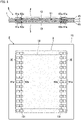
- Fig. 2 includes a side sectional view and a plan view showing an MEA 2 with gas diffusion layer according to the first preferred embodiment.
- the MEA 2 with gas diffusion layer includes the MEA 1 shown in Fig. 1 , and two gas diffusion layers 3.
- One of the two gas diffusion layers 3 is located on one side of the MEA 1, and the other gas diffusion layer 3 is located on an opposite side of the MEA 1. Namely, the MEA 1 is caught between the two gas diffusion layers 3.
- the following description is intended for a configuration of the MEA 2 with gas diffusion layer closer to the one side than the electrolyte membrane 11.
- a configuration of the MEA 2 with gas diffusion layer closer to the opposite side than the electrolyte membrane 11 is the same as the configuration on the one side.
- the gas diffusion layer 3 has a larger area than the catalyst layer 13 and is provided in such a manner as to cover an outer surface of the catalyst layer 13 entirely. As shown in Fig. 2 , the gas diffusion layer 3 has a protrusion protruding externally from the outer periphery 131 of the catalyst layer 13. The protrusion of the gas diffusion layer 3 protruding from the catalyst layer 13 is adhesively bonded to a surface of the subgasket 15 on the one side through two first bonding parts 41.
- the gas diffusion layer 3 has a rectangular shape, for example.
- the shape of the gas diffusion layer 3 is not limited to a rectangle but may be a circle (including an oval) or a polygon, for example.
- the gas diffusion layer 3 includes a gas diffusion layer base material 31 and a microporous layer 33.
- the microporous layer 33 is located between the gas diffusion layer base material 31 and the catalyst layer 13.
- the gas diffusion layer base material 31 is made of a porous member having conductivity.
- the gas diffusion layer base material 31 is carbon paper or carbon cloth.
- the gas diffusion layer base material 31 has functions such as supplying hydrogen or air as fuel to an electrode (catalyst), collecting electrons generated by chemical reaction at the electrode, and moisturizing the electrolyte membrane 11 and discharging purified water.
- the microporous layer 33 is adhesively bonded to the gas diffusion layer base material 31.
- the microporous layer 33 is a coating film formed by applying a paste composition for microporous layer formation onto one surface of the gas diffusion layer base material 31, and then drying the paste composition, for example.
- the paste composition contains a water-repelling resin made of non-polymer fluorine material (polytetrafluoroethylene (PTEE), for example), and a conductive carbon material such as carbon black, carbon nanotubes, or carbon nanofibers, for example.
- the paste composition contains an adhesive (such as thermoplastic resin), if necessary.
- the microporous layer 33 changes a component ratio of the composition to provide the gas diffusion layer 3 with a function of retaining a larger amount of moisture in the electrolyte membrane 11 or a function of discharging redundant moisture in the MEA 1 efficiently, for example.
- the power of adhesion of the microporous layer 33 to the gas diffusion layer base material 31 determined by a test under ISO 29862:2007 (JIS Z 0237:2009) is preferably equal to or greater than 40 g/25 mm, more preferably, equal to or greater than 50 g/25 mm, more preferably, equal to or greater than 60 g/25 mm, still more preferably, equal to or greater than 65 g/25 mm.
- the power of adhesion of the microporous layer 33 to the gas diffusion layer base material 31 determined by the test under ISO 29862:2007 is preferably equal to or less than 200 g/25 mm, more preferably, equal to or less than 190 g/25 mm, more preferably, equal to or less than 180 g/25 mm, more preferably, equal to or less than 170 g/25 mm, still more preferably, equal to or less than 160 g/25 mm.
- the adhesion power By setting the adhesion power to be equal to or less than 200 g/25 mm, reduction in gas-permeability of the gas diffusion layer 3 is suppressed, thereby suppressing reduction in cell properties of the MEA 1.
- the first bonding parts 41 are arranged at positions overlapping periphery parts 3E of the gas diffusion layer 3 in the thickness direction.
- the first bonding parts 41 are provided at the periphery parts 3E, 3E forming two of the four sides of the rectangular gas diffusion layer 3 facing each other.
- the first bonding parts 41 each have a continuous linear pattern (here, a pattern like a straight line) extending parallel to the periphery part 3E of the gas diffusion layer 3.
- the periphery part 3E of the gas diffusion layer 3 includes a periphery region of the main surface of the gas diffusion layer 3.
- the periphery region is a region having a width of about several centimeters defined at an inner position from a periphery (periphery edge) of the gas diffusion layer 3.
- first bonding parts 41 are provided only at the periphery parts 3E, 3E forming the two sides of the gas diffusion layer 3 facing each other in the example of Fig. 2 , they may further be provided at the other periphery parts 3E, 3E.
- the first bonding parts 41 are each located external to the outer periphery 131 of the catalyst layer 13. Specifically, the first bonding part 41 does not overlap the catalyst layer 13 in the thickness direction. The first bonding part 41 extends in a direction parallel to the outer periphery 131 of the catalyst layer 13.
- the first bonding part 41 is formed by applying an adhesive, for example.
- the adhesive is not particularly limited, the following materials are preferably used.
- the adhesive is a thermoplastic adhesive, a thermosetting adhesive, an elastomer-based adhesive, or an adhesive prepared by combining some of these adhesives.
- the MEA 2 with gas diffusion layer is prepared by the following procedure, for example.
- Applying the adhesive directly to the gas diffusion layer 3 allows the adhesive to be applied more correctly to the periphery part 3E of the gas diffusion layer 3 than applying the adhesive to the subgasket 15. This allows bonding of the gas diffusion layer 3 to the subgasket 15 at the periphery part 3E of the gas diffusion layer 3, thereby reducing the occurrence of stripping of the gas diffusion layer 3 from the subgasket 15.
- Applying the adhesive for the first bonding part 41 in a linear pattern allows the application to be performed more simply than applying the adhesive in a non-linear pattern. This makes it possible to increase a speed of manufacturing the MEA 2 with gas diffusion layer.
- the first bonding part 41 has a width W1 that is preferably equal to or less than 10 mm, more preferably, equal to or less than 2 mm. This makes it possible to suppress reduction in performance of the MEA 1 to be caused by adherence of the adhesive in the first bonding part 41 to the catalyst layer 13.
- the thickness (dry thickness) of the first bonding part 41 is preferably equal to or less than 5 ⁇ m, more preferably, equal to or less than 1 ⁇ m. Setting the thickness of the first bonding part 41 in this way makes it possible to restrict the thickness of the MEA 2 with gas diffusion layer.
- the gas diffusion layer 3 is adhesively bonded to the subgasket 15 only at the two linear first bonding parts 41. Except for these parts, the MEA 2 with gas diffusion layer is not adhesively bonded to the MEA 1. Hence, vibration such as an flapping is likely to occur at the gas diffusion layer 3 during handling of the MEA 2 with gas diffusion layer. The occurrence of vibration at the gas diffusion layer 3 causes a risk of stripping of the microporous layer 33 from the gas diffusion layer base material 31.
- the power of adhesion of the microporous layer 33 to the gas diffusion layer base material 31 is set to be equal to or greater than 40 g/25 mm, thereby reducing the occurrence of stripping of the microporous layer 33 from the gas diffusion layer base material 31 during handling of the MEA 2 with gas diffusion layer.
- Fig. 3 includes a side sectional view and a plan view showing an MEA 2 with gas diffusion layer according to a second preferred embodiment.
- the MEA 2 with gas diffusion layer according to the second preferred embodiment includes four first bonding parts 41a instead of the four first bonding parts 41.
- the first bonding parts 41a each have a linear pattern (a pattern like a straight line) extending discontinuously.
- the first bonding part 41a is formed by applying an adhesive with a pitch of equal to or less than 30 mm, for example.
- the first bonding part 41a has a width W1 and a dry thickness that can be the same as the width W1 and the dry thickness of the first bonding part 41 shown in Fig. 2 , for example.
- Forming the first bonding part 41a into the discontinuous linear pattern allows reduction in the amount of usage of the adhesive.
- the gas diffusion layer 3 is bonded to the subgasket 15 in a smaller area.
- an flapping is more likely to occur at the gas diffusion layer 3 during handling of the MEA 2 with gas diffusion layer.
- the power of adhesion of the microporous layer 33 to the gas diffusion layer base material 31 is set to be equal to or greater than 40 g/25 mm, thereby reducing the occurrence of stripping of the microporous layer 33.
- first bonding parts 41 are replaced with the first bonding parts 41a in the second preferred embodiment, only some of the four first bonding parts 41 may be replaced with the first bonding parts 41a.
- Fig. 4 includes a side sectional view and a plan view showing an MEA 2 with gas diffusion layer according to a third preferred embodiment.
- the MEA 2 with gas diffusion layer according to the third preferred embodiment further includes four second bonding parts 42.
- the second bonding parts 42 are regions each formed by applying an adhesive in a linear pattern.
- Two of the four second bonding parts 42 are located on one side of the MEA 1, and the other two are located on an opposite side of the MEA 1.
- the following description is intended for a configuration of the MEA 2 with gas diffusion layer closer to the one side than the electrolyte membrane 11.
- a configuration of the MEA 2 with gas diffusion layer closer to the opposite side than the electrolyte membrane 11 will not be described as it is the same as the configuration on the one side.
- the two second bonding parts 42 are located between the two first bonding parts 41.
- the second bonding parts 42 are each arranged at a position overlapping the outer periphery 131 of the catalyst layer 13 and overlapping an inner periphery of the subgasket 15 in the thickness direction.
- the gas diffusion layer 3 is adhesively bonded through the two second bonding parts 42 to the outer periphery 131 of the catalyst layer 13 and to the inner periphery of the subgasket 15.
- the first bonding part 41 contains ionomer in a range from 0.05 to 1.5 mg/cm 2 , more preferably, in a range from 1.0 to 1.5 mg/cm 2 .
- the ionomer is Nafion (registered trademark), for example.
- the second bonding part 42 has an area overlapping the outer periphery 131 of the catalyst layer 13 in the thickness direction and an area overlapping the inner periphery of the subgasket 15 in the thickness direction.
- the second bonding part 42 contains ionomer in a range from 0.025 to 1.0 mg/cm 2 , for example.
- the ionomer is Nafion (registered trademark), for example.
- Fig. 5 includes a side sectional view and a plan view showing an MEA 2 with gas diffusion layer according to a fourth preferred embodiment.
- the MEA 2 with gas diffusion layer according to the fourth preferred embodiment includes a second bonding part 42a instead of the second bonding part 42.
- the second bonding part 42a has a linear pattern extending discontinuously in a direction parallel to the outer periphery 131.
- the second bonding part 42a is formed by applying an adhesive with a pitch of equal to or less than 30 mm.
- Forming the second bonding part 42a into the discontinuous linear pattern allows reduction in the amount of usage of the adhesive.
- the gas diffusion layer 3 is adhesively bonded to the subgasket 15 in a smaller area.
- an flapping is likely to occur at the gas diffusion layer 3 during handling of the MEA 2 with gas diffusion layer.
- the microporous layer 33 is adhesively bonded to the gas diffusion layer base material 31 with adhesion power of equal to or greater than 40 g/25 mm, thereby reducing the occurrence of stripping of the microporous layer 33.
Landscapes
- Chemical & Material Sciences (AREA)
- Chemical Kinetics & Catalysis (AREA)
- Electrochemistry (AREA)
- General Chemical & Material Sciences (AREA)
- Engineering & Computer Science (AREA)
- Manufacturing & Machinery (AREA)
- Life Sciences & Earth Sciences (AREA)
- Sustainable Development (AREA)
- Sustainable Energy (AREA)
- Fuel Cell (AREA)
- Inert Electrodes (AREA)
- Separation Using Semi-Permeable Membranes (AREA)
Applications Claiming Priority (1)
| Application Number | Priority Date | Filing Date | Title |
|---|---|---|---|
| JP2021046438A JP7307109B2 (ja) | 2021-03-19 | 2021-03-19 | ガス拡散層付膜電極接合体およびその製造方法 |
Publications (2)
| Publication Number | Publication Date |
|---|---|
| EP4068433A1 true EP4068433A1 (de) | 2022-10-05 |
| EP4068433B1 EP4068433B1 (de) | 2024-04-24 |
Family
ID=79020968
Family Applications (1)
| Application Number | Title | Priority Date | Filing Date |
|---|---|---|---|
| EP21216846.2A Active EP4068433B1 (de) | 2021-03-19 | 2021-12-22 | Membranelektrodenanordnung mit einer gasdiffusionsschicht und verfahren zur herstellung einer membranelektrodenanordnung mit einer gasdiffusionsschicht |
Country Status (4)
| Country | Link |
|---|---|
| EP (1) | EP4068433B1 (de) |
| JP (1) | JP7307109B2 (de) |
| KR (1) | KR20220131150A (de) |
| CN (1) | CN115117407B (de) |
Cited By (1)
| Publication number | Priority date | Publication date | Assignee | Title |
|---|---|---|---|---|
| DE102023128503B3 (de) | 2023-06-16 | 2024-09-26 | GM Global Technology Operations LLC | Leiteranordnung für eine Protonenaustauschmembran-Brennstoffzelle |
Citations (5)
| Publication number | Priority date | Publication date | Assignee | Title |
|---|---|---|---|---|
| JP2010015963A (ja) | 2008-07-04 | 2010-01-21 | Hyundai Motor Co Ltd | 燃料電池スタックの膜電極接合体とガス拡散層間の接合方法 |
| US20110318667A1 (en) * | 2010-06-23 | 2011-12-29 | Gm Global Technology Operations, Inc. | Integrated fuel cell assembly and method of making |
| WO2015146980A1 (ja) * | 2014-03-24 | 2015-10-01 | 凸版印刷株式会社 | 膜電極接合体、および、固体高分子形燃料電池 |
| JP2017188346A (ja) * | 2016-04-07 | 2017-10-12 | トヨタ自動車株式会社 | 燃料電池 |
| US20200280085A1 (en) * | 2019-03-01 | 2020-09-03 | Toyota Jidosha Kabushiki Kaisha | Fuel cell and method for manufacturing the fuel cell |
Family Cites Families (10)
| Publication number | Priority date | Publication date | Assignee | Title |
|---|---|---|---|---|
| JP2002343377A (ja) * | 2001-05-17 | 2002-11-29 | Matsushita Electric Ind Co Ltd | 燃料電池用電解質膜−電極接合体およびその製造方法 |
| CN101814616A (zh) * | 2010-04-15 | 2010-08-25 | 武汉理工新能源有限公司 | 一种燃料电池用气体扩散层及其制备方法 |
| JP6104050B2 (ja) * | 2012-06-29 | 2017-03-29 | 本田技研工業株式会社 | 燃料電池用電解質膜・電極構造体 |
| JP6064884B2 (ja) * | 2013-12-10 | 2017-01-25 | トヨタ自動車株式会社 | 発電体 |
| KR101601403B1 (ko) * | 2014-04-01 | 2016-03-09 | 현대자동차주식회사 | 연료전지용 기체확산층의 계면 강도 측정 장치 및 방법 |
| JP2016219179A (ja) | 2015-05-18 | 2016-12-22 | 凸版印刷株式会社 | 膜電極構造体及び固体高分子形燃料電池、並びに膜電極構造体の製造方法 |
| KR20170103566A (ko) | 2016-03-04 | 2017-09-13 | 현대자동차주식회사 | 연료전지 부품 및 이의 제조장치 |
| WO2018186293A1 (ja) | 2017-04-03 | 2018-10-11 | 東レ株式会社 | ガス拡散電極基材の製造方法、および燃料電池 |
| KR102163539B1 (ko) * | 2017-09-29 | 2020-10-08 | 코오롱인더스트리 주식회사 | 막-전극 어셈블리, 이의 제조 방법, 및 이를 포함하는 연료 전지 스택 |
| JP7040303B2 (ja) * | 2018-06-11 | 2022-03-23 | トヨタ自動車株式会社 | 燃料電池セル |
-
2021
- 2021-03-19 JP JP2021046438A patent/JP7307109B2/ja active Active
- 2021-12-22 EP EP21216846.2A patent/EP4068433B1/de active Active
-
2022
- 2022-01-19 KR KR1020220007763A patent/KR20220131150A/ko not_active Ceased
- 2022-02-09 CN CN202210123264.0A patent/CN115117407B/zh active Active
Patent Citations (5)
| Publication number | Priority date | Publication date | Assignee | Title |
|---|---|---|---|---|
| JP2010015963A (ja) | 2008-07-04 | 2010-01-21 | Hyundai Motor Co Ltd | 燃料電池スタックの膜電極接合体とガス拡散層間の接合方法 |
| US20110318667A1 (en) * | 2010-06-23 | 2011-12-29 | Gm Global Technology Operations, Inc. | Integrated fuel cell assembly and method of making |
| WO2015146980A1 (ja) * | 2014-03-24 | 2015-10-01 | 凸版印刷株式会社 | 膜電極接合体、および、固体高分子形燃料電池 |
| JP2017188346A (ja) * | 2016-04-07 | 2017-10-12 | トヨタ自動車株式会社 | 燃料電池 |
| US20200280085A1 (en) * | 2019-03-01 | 2020-09-03 | Toyota Jidosha Kabushiki Kaisha | Fuel cell and method for manufacturing the fuel cell |
Cited By (1)
| Publication number | Priority date | Publication date | Assignee | Title |
|---|---|---|---|---|
| DE102023128503B3 (de) | 2023-06-16 | 2024-09-26 | GM Global Technology Operations LLC | Leiteranordnung für eine Protonenaustauschmembran-Brennstoffzelle |
Also Published As
| Publication number | Publication date |
|---|---|
| JP7307109B2 (ja) | 2023-07-11 |
| EP4068433B1 (de) | 2024-04-24 |
| CN115117407A (zh) | 2022-09-27 |
| JP2022145150A (ja) | 2022-10-03 |
| KR20220131150A (ko) | 2022-09-27 |
| CN115117407B (zh) | 2024-08-27 |
Similar Documents
| Publication | Publication Date | Title |
|---|---|---|
| US9083012B2 (en) | Membrane electrode assembly having an adhesive layer impregnating through an electrocatalyst layer and into a first gas diffusion substrate | |
| CN104081572B (zh) | 固体高分子燃料电池用膜电极接合体 | |
| JP5326189B2 (ja) | 電解質膜−電極接合体およびその製造方法 | |
| EP2112705A1 (de) | Gebondeter film-film-verstärkungsgliedkörper, gebondeter film-katalysatorschicht-körper, gebondeter film-elektroden-körper und brennstoffzelle des polyelektrolyttyps | |
| JP2003178780A (ja) | 高分子電解質型燃料電池システム、および高分子電解質型燃料電池の運転方法 | |
| JP4843985B2 (ja) | 固体高分子形燃料電池用ガスケット付き電解質膜−電極接合体及びその製造方法 | |
| EP4068433B1 (de) | Membranelektrodenanordnung mit einer gasdiffusionsschicht und verfahren zur herstellung einer membranelektrodenanordnung mit einer gasdiffusionsschicht | |
| WO2007113592A1 (en) | Assembly for use in a fuel cell | |
| US12542296B2 (en) | System and method for a fuel cell subgasket active area edge with through-plane photon conduction | |
| JP2006338943A (ja) | 電解質膜−電極接合体 | |
| JP2021180154A (ja) | 燃料電池スタック | |
| EP3504746B1 (de) | Brennstoffzelle mit verbesserter haltbarkeit | |
| JP4511965B2 (ja) | 膜−触媒層接合体の製造方法及び膜−電極接合体の製造方法 | |
| EP2120277B1 (de) | Membranelektrodenanordnung für eine Brennstoffzelle, Verfahren zur Herstellung davon und Brennstoffzellensystem damit | |
| JP7040303B2 (ja) | 燃料電池セル | |
| JP7452465B2 (ja) | 燃料電池 | |
| JP5280414B2 (ja) | 膜・電極構造体および燃料電池 | |
| JP2013004390A (ja) | 燃料電池用電解質膜−触媒層接合体の製造方法 | |
| JP2012064377A (ja) | 燃料電池用の膜電極接合体とこれを有する燃料電池 | |
| JP2022022581A (ja) | 燃料電池 | |
| JP6412995B2 (ja) | 電解質膜・電極構造体の製造方法 | |
| JP2024110212A (ja) | 固体高分子形電気化学セル | |
| JP2007005245A (ja) | 燃料電池及びその製造方法 | |
| JP2004319303A (ja) | 固体高分子型燃料電池とその製造方法 | |
| JP2015162308A (ja) | 膜電極接合体、燃料電池、及び膜電極接合体の製造方法 |
Legal Events
| Date | Code | Title | Description |
|---|---|---|---|
| PUAI | Public reference made under article 153(3) epc to a published international application that has entered the european phase |
Free format text: ORIGINAL CODE: 0009012 |
|
| STAA | Information on the status of an ep patent application or granted ep patent |
Free format text: STATUS: THE APPLICATION HAS BEEN PUBLISHED |
|
| AK | Designated contracting states |
Kind code of ref document: A1 Designated state(s): AL AT BE BG CH CY CZ DE DK EE ES FI FR GB GR HR HU IE IS IT LI LT LU LV MC MK MT NL NO PL PT RO RS SE SI SK SM TR |
|
| STAA | Information on the status of an ep patent application or granted ep patent |
Free format text: STATUS: REQUEST FOR EXAMINATION WAS MADE |
|
| 17P | Request for examination filed |
Effective date: 20230328 |
|
| RBV | Designated contracting states (corrected) |
Designated state(s): AL AT BE BG CH CY CZ DE DK EE ES FI FR GB GR HR HU IE IS IT LI LT LU LV MC MK MT NL NO PL PT RO RS SE SI SK SM TR |
|
| GRAP | Despatch of communication of intention to grant a patent |
Free format text: ORIGINAL CODE: EPIDOSNIGR1 |
|
| STAA | Information on the status of an ep patent application or granted ep patent |
Free format text: STATUS: GRANT OF PATENT IS INTENDED |
|
| INTG | Intention to grant announced |
Effective date: 20231201 |
|
| GRAS | Grant fee paid |
Free format text: ORIGINAL CODE: EPIDOSNIGR3 |
|
| GRAA | (expected) grant |
Free format text: ORIGINAL CODE: 0009210 |
|
| STAA | Information on the status of an ep patent application or granted ep patent |
Free format text: STATUS: THE PATENT HAS BEEN GRANTED |
|
| P01 | Opt-out of the competence of the unified patent court (upc) registered |
Effective date: 20240219 |
|
| AK | Designated contracting states |
Kind code of ref document: B1 Designated state(s): AL AT BE BG CH CY CZ DE DK EE ES FI FR GB GR HR HU IE IS IT LI LT LU LV MC MK MT NL NO PL PT RO RS SE SI SK SM TR |
|
| REG | Reference to a national code |
Ref country code: GB Ref legal event code: FG4D |
|
| REG | Reference to a national code |
Ref country code: CH Ref legal event code: EP |
|
| REG | Reference to a national code |
Ref country code: DE Ref legal event code: R096 Ref document number: 602021012226 Country of ref document: DE |
|
| REG | Reference to a national code |
Ref country code: IE Ref legal event code: FG4D |
|
| REG | Reference to a national code |
Ref country code: LT Ref legal event code: MG9D |
|
| REG | Reference to a national code |
Ref country code: NL Ref legal event code: MP Effective date: 20240424 |
|
| REG | Reference to a national code |
Ref country code: AT Ref legal event code: MK05 Ref document number: 1680605 Country of ref document: AT Kind code of ref document: T Effective date: 20240424 |
|
| PG25 | Lapsed in a contracting state [announced via postgrant information from national office to epo] |
Ref country code: NL Free format text: LAPSE BECAUSE OF FAILURE TO SUBMIT A TRANSLATION OF THE DESCRIPTION OR TO PAY THE FEE WITHIN THE PRESCRIBED TIME-LIMIT Effective date: 20240424 |
|
| PG25 | Lapsed in a contracting state [announced via postgrant information from national office to epo] |
Ref country code: NL Free format text: LAPSE BECAUSE OF FAILURE TO SUBMIT A TRANSLATION OF THE DESCRIPTION OR TO PAY THE FEE WITHIN THE PRESCRIBED TIME-LIMIT Effective date: 20240424 |
|
| PG25 | Lapsed in a contracting state [announced via postgrant information from national office to epo] |
Ref country code: IS Free format text: LAPSE BECAUSE OF FAILURE TO SUBMIT A TRANSLATION OF THE DESCRIPTION OR TO PAY THE FEE WITHIN THE PRESCRIBED TIME-LIMIT Effective date: 20240824 |
|
| PG25 | Lapsed in a contracting state [announced via postgrant information from national office to epo] |
Ref country code: BG Free format text: LAPSE BECAUSE OF FAILURE TO SUBMIT A TRANSLATION OF THE DESCRIPTION OR TO PAY THE FEE WITHIN THE PRESCRIBED TIME-LIMIT Effective date: 20240424 |
|
| PG25 | Lapsed in a contracting state [announced via postgrant information from national office to epo] |
Ref country code: HR Free format text: LAPSE BECAUSE OF FAILURE TO SUBMIT A TRANSLATION OF THE DESCRIPTION OR TO PAY THE FEE WITHIN THE PRESCRIBED TIME-LIMIT Effective date: 20240424 Ref country code: FI Free format text: LAPSE BECAUSE OF FAILURE TO SUBMIT A TRANSLATION OF THE DESCRIPTION OR TO PAY THE FEE WITHIN THE PRESCRIBED TIME-LIMIT Effective date: 20240424 |
|
| PG25 | Lapsed in a contracting state [announced via postgrant information from national office to epo] |
Ref country code: GR Free format text: LAPSE BECAUSE OF FAILURE TO SUBMIT A TRANSLATION OF THE DESCRIPTION OR TO PAY THE FEE WITHIN THE PRESCRIBED TIME-LIMIT Effective date: 20240725 |
|
| PG25 | Lapsed in a contracting state [announced via postgrant information from national office to epo] |
Ref country code: PT Free format text: LAPSE BECAUSE OF FAILURE TO SUBMIT A TRANSLATION OF THE DESCRIPTION OR TO PAY THE FEE WITHIN THE PRESCRIBED TIME-LIMIT Effective date: 20240826 |
|
| PG25 | Lapsed in a contracting state [announced via postgrant information from national office to epo] |
Ref country code: ES Free format text: LAPSE BECAUSE OF FAILURE TO SUBMIT A TRANSLATION OF THE DESCRIPTION OR TO PAY THE FEE WITHIN THE PRESCRIBED TIME-LIMIT Effective date: 20240424 |
|
| PG25 | Lapsed in a contracting state [announced via postgrant information from national office to epo] |
Ref country code: AT Free format text: LAPSE BECAUSE OF FAILURE TO SUBMIT A TRANSLATION OF THE DESCRIPTION OR TO PAY THE FEE WITHIN THE PRESCRIBED TIME-LIMIT Effective date: 20240424 |
|
| PG25 | Lapsed in a contracting state [announced via postgrant information from national office to epo] |
Ref country code: PL Free format text: LAPSE BECAUSE OF FAILURE TO SUBMIT A TRANSLATION OF THE DESCRIPTION OR TO PAY THE FEE WITHIN THE PRESCRIBED TIME-LIMIT Effective date: 20240424 |
|
| PG25 | Lapsed in a contracting state [announced via postgrant information from national office to epo] |
Ref country code: LV Free format text: LAPSE BECAUSE OF FAILURE TO SUBMIT A TRANSLATION OF THE DESCRIPTION OR TO PAY THE FEE WITHIN THE PRESCRIBED TIME-LIMIT Effective date: 20240424 |
|
| PG25 | Lapsed in a contracting state [announced via postgrant information from national office to epo] |
Ref country code: PT Free format text: LAPSE BECAUSE OF FAILURE TO SUBMIT A TRANSLATION OF THE DESCRIPTION OR TO PAY THE FEE WITHIN THE PRESCRIBED TIME-LIMIT Effective date: 20240826 Ref country code: PL Free format text: LAPSE BECAUSE OF FAILURE TO SUBMIT A TRANSLATION OF THE DESCRIPTION OR TO PAY THE FEE WITHIN THE PRESCRIBED TIME-LIMIT Effective date: 20240424 Ref country code: NO Free format text: LAPSE BECAUSE OF FAILURE TO SUBMIT A TRANSLATION OF THE DESCRIPTION OR TO PAY THE FEE WITHIN THE PRESCRIBED TIME-LIMIT Effective date: 20240724 Ref country code: LV Free format text: LAPSE BECAUSE OF FAILURE TO SUBMIT A TRANSLATION OF THE DESCRIPTION OR TO PAY THE FEE WITHIN THE PRESCRIBED TIME-LIMIT Effective date: 20240424 Ref country code: IS Free format text: LAPSE BECAUSE OF FAILURE TO SUBMIT A TRANSLATION OF THE DESCRIPTION OR TO PAY THE FEE WITHIN THE PRESCRIBED TIME-LIMIT Effective date: 20240824 Ref country code: HR Free format text: LAPSE BECAUSE OF FAILURE TO SUBMIT A TRANSLATION OF THE DESCRIPTION OR TO PAY THE FEE WITHIN THE PRESCRIBED TIME-LIMIT Effective date: 20240424 Ref country code: GR Free format text: LAPSE BECAUSE OF FAILURE TO SUBMIT A TRANSLATION OF THE DESCRIPTION OR TO PAY THE FEE WITHIN THE PRESCRIBED TIME-LIMIT Effective date: 20240725 Ref country code: FI Free format text: LAPSE BECAUSE OF FAILURE TO SUBMIT A TRANSLATION OF THE DESCRIPTION OR TO PAY THE FEE WITHIN THE PRESCRIBED TIME-LIMIT Effective date: 20240424 Ref country code: ES Free format text: LAPSE BECAUSE OF FAILURE TO SUBMIT A TRANSLATION OF THE DESCRIPTION OR TO PAY THE FEE WITHIN THE PRESCRIBED TIME-LIMIT Effective date: 20240424 Ref country code: BG Free format text: LAPSE BECAUSE OF FAILURE TO SUBMIT A TRANSLATION OF THE DESCRIPTION OR TO PAY THE FEE WITHIN THE PRESCRIBED TIME-LIMIT Effective date: 20240424 Ref country code: AT Free format text: LAPSE BECAUSE OF FAILURE TO SUBMIT A TRANSLATION OF THE DESCRIPTION OR TO PAY THE FEE WITHIN THE PRESCRIBED TIME-LIMIT Effective date: 20240424 Ref country code: RS Free format text: LAPSE BECAUSE OF FAILURE TO SUBMIT A TRANSLATION OF THE DESCRIPTION OR TO PAY THE FEE WITHIN THE PRESCRIBED TIME-LIMIT Effective date: 20240724 |
|
| PG25 | Lapsed in a contracting state [announced via postgrant information from national office to epo] |
Ref country code: DK Free format text: LAPSE BECAUSE OF FAILURE TO SUBMIT A TRANSLATION OF THE DESCRIPTION OR TO PAY THE FEE WITHIN THE PRESCRIBED TIME-LIMIT Effective date: 20240424 |
|
| PG25 | Lapsed in a contracting state [announced via postgrant information from national office to epo] |
Ref country code: EE Free format text: LAPSE BECAUSE OF FAILURE TO SUBMIT A TRANSLATION OF THE DESCRIPTION OR TO PAY THE FEE WITHIN THE PRESCRIBED TIME-LIMIT Effective date: 20240424 |
|
| PG25 | Lapsed in a contracting state [announced via postgrant information from national office to epo] |
Ref country code: CZ Free format text: LAPSE BECAUSE OF FAILURE TO SUBMIT A TRANSLATION OF THE DESCRIPTION OR TO PAY THE FEE WITHIN THE PRESCRIBED TIME-LIMIT Effective date: 20240424 |
|
| PG25 | Lapsed in a contracting state [announced via postgrant information from national office to epo] |
Ref country code: SK Free format text: LAPSE BECAUSE OF FAILURE TO SUBMIT A TRANSLATION OF THE DESCRIPTION OR TO PAY THE FEE WITHIN THE PRESCRIBED TIME-LIMIT Effective date: 20240424 Ref country code: RO Free format text: LAPSE BECAUSE OF FAILURE TO SUBMIT A TRANSLATION OF THE DESCRIPTION OR TO PAY THE FEE WITHIN THE PRESCRIBED TIME-LIMIT Effective date: 20240424 |
|
| REG | Reference to a national code |
Ref country code: DE Ref legal event code: R097 Ref document number: 602021012226 Country of ref document: DE |
|
| PG25 | Lapsed in a contracting state [announced via postgrant information from national office to epo] |
Ref country code: SM Free format text: LAPSE BECAUSE OF FAILURE TO SUBMIT A TRANSLATION OF THE DESCRIPTION OR TO PAY THE FEE WITHIN THE PRESCRIBED TIME-LIMIT Effective date: 20240424 |
|
| PG25 | Lapsed in a contracting state [announced via postgrant information from national office to epo] |
Ref country code: SM Free format text: LAPSE BECAUSE OF FAILURE TO SUBMIT A TRANSLATION OF THE DESCRIPTION OR TO PAY THE FEE WITHIN THE PRESCRIBED TIME-LIMIT Effective date: 20240424 Ref country code: SK Free format text: LAPSE BECAUSE OF FAILURE TO SUBMIT A TRANSLATION OF THE DESCRIPTION OR TO PAY THE FEE WITHIN THE PRESCRIBED TIME-LIMIT Effective date: 20240424 Ref country code: RO Free format text: LAPSE BECAUSE OF FAILURE TO SUBMIT A TRANSLATION OF THE DESCRIPTION OR TO PAY THE FEE WITHIN THE PRESCRIBED TIME-LIMIT Effective date: 20240424 Ref country code: EE Free format text: LAPSE BECAUSE OF FAILURE TO SUBMIT A TRANSLATION OF THE DESCRIPTION OR TO PAY THE FEE WITHIN THE PRESCRIBED TIME-LIMIT Effective date: 20240424 Ref country code: DK Free format text: LAPSE BECAUSE OF FAILURE TO SUBMIT A TRANSLATION OF THE DESCRIPTION OR TO PAY THE FEE WITHIN THE PRESCRIBED TIME-LIMIT Effective date: 20240424 Ref country code: CZ Free format text: LAPSE BECAUSE OF FAILURE TO SUBMIT A TRANSLATION OF THE DESCRIPTION OR TO PAY THE FEE WITHIN THE PRESCRIBED TIME-LIMIT Effective date: 20240424 |
|
| PLBE | No opposition filed within time limit |
Free format text: ORIGINAL CODE: 0009261 |
|
| STAA | Information on the status of an ep patent application or granted ep patent |
Free format text: STATUS: NO OPPOSITION FILED WITHIN TIME LIMIT |
|
| 26N | No opposition filed |
Effective date: 20250127 |
|
| PG25 | Lapsed in a contracting state [announced via postgrant information from national office to epo] |
Ref country code: SI Free format text: LAPSE BECAUSE OF FAILURE TO SUBMIT A TRANSLATION OF THE DESCRIPTION OR TO PAY THE FEE WITHIN THE PRESCRIBED TIME-LIMIT Effective date: 20240424 |
|
| PG25 | Lapsed in a contracting state [announced via postgrant information from national office to epo] |
Ref country code: MC Free format text: LAPSE BECAUSE OF FAILURE TO SUBMIT A TRANSLATION OF THE DESCRIPTION OR TO PAY THE FEE WITHIN THE PRESCRIBED TIME-LIMIT Effective date: 20240424 |
|
| REG | Reference to a national code |
Ref country code: CH Ref legal event code: PL |
|
| PG25 | Lapsed in a contracting state [announced via postgrant information from national office to epo] |
Ref country code: LU Free format text: LAPSE BECAUSE OF NON-PAYMENT OF DUE FEES Effective date: 20241222 |
|
| PG25 | Lapsed in a contracting state [announced via postgrant information from national office to epo] |
Ref country code: SE Free format text: LAPSE BECAUSE OF FAILURE TO SUBMIT A TRANSLATION OF THE DESCRIPTION OR TO PAY THE FEE WITHIN THE PRESCRIBED TIME-LIMIT Effective date: 20240424 |
|
| REG | Reference to a national code |
Ref country code: BE Ref legal event code: MM Effective date: 20241231 |
|
| PG25 | Lapsed in a contracting state [announced via postgrant information from national office to epo] |
Ref country code: BE Free format text: LAPSE BECAUSE OF NON-PAYMENT OF DUE FEES Effective date: 20241231 |
|
| PG25 | Lapsed in a contracting state [announced via postgrant information from national office to epo] |
Ref country code: CH Free format text: LAPSE BECAUSE OF NON-PAYMENT OF DUE FEES Effective date: 20241231 |
|
| PG25 | Lapsed in a contracting state [announced via postgrant information from national office to epo] |
Ref country code: IE Free format text: LAPSE BECAUSE OF NON-PAYMENT OF DUE FEES Effective date: 20241222 |
|
| PGFP | Annual fee paid to national office [announced via postgrant information from national office to epo] |
Ref country code: DE Payment date: 20251028 Year of fee payment: 5 |
|
| PGFP | Annual fee paid to national office [announced via postgrant information from national office to epo] |
Ref country code: GB Payment date: 20251030 Year of fee payment: 5 |
|
| PGFP | Annual fee paid to national office [announced via postgrant information from national office to epo] |
Ref country code: FR Payment date: 20251110 Year of fee payment: 5 |
|
| PG25 | Lapsed in a contracting state [announced via postgrant information from national office to epo] |
Ref country code: IT Free format text: LAPSE BECAUSE OF FAILURE TO SUBMIT A TRANSLATION OF THE DESCRIPTION OR TO PAY THE FEE WITHIN THE PRESCRIBED TIME-LIMIT Effective date: 20240424 |