EP4067221A1 - Schiffsantriebsvorrichtung - Google Patents
Schiffsantriebsvorrichtung Download PDFInfo
- Publication number
- EP4067221A1 EP4067221A1 EP20891782.3A EP20891782A EP4067221A1 EP 4067221 A1 EP4067221 A1 EP 4067221A1 EP 20891782 A EP20891782 A EP 20891782A EP 4067221 A1 EP4067221 A1 EP 4067221A1
- Authority
- EP
- European Patent Office
- Prior art keywords
- propulsion
- unit
- propulsion unit
- units
- fault
- Prior art date
- Legal status (The legal status is an assumption and is not a legal conclusion. Google has not performed a legal analysis and makes no representation as to the accuracy of the status listed.)
- Withdrawn
Links
Images



Classifications
-
- B—PERFORMING OPERATIONS; TRANSPORTING
- B63—SHIPS OR OTHER WATERBORNE VESSELS; RELATED EQUIPMENT
- B63H—MARINE PROPULSION OR STEERING
- B63H21/00—Use of propulsion power plant or units on vessels
- B63H21/21—Control means for engine or transmission, specially adapted for use on marine vessels
-
- B—PERFORMING OPERATIONS; TRANSPORTING
- B63—SHIPS OR OTHER WATERBORNE VESSELS; RELATED EQUIPMENT
- B63B—SHIPS OR OTHER WATERBORNE VESSELS; EQUIPMENT FOR SHIPPING
- B63B79/00—Monitoring properties or operating parameters of vessels in operation
- B63B79/30—Monitoring properties or operating parameters of vessels in operation for diagnosing, testing or predicting the integrity or performance of vessels
-
- B—PERFORMING OPERATIONS; TRANSPORTING
- B63—SHIPS OR OTHER WATERBORNE VESSELS; RELATED EQUIPMENT
- B63B—SHIPS OR OTHER WATERBORNE VESSELS; EQUIPMENT FOR SHIPPING
- B63B79/00—Monitoring properties or operating parameters of vessels in operation
- B63B79/40—Monitoring properties or operating parameters of vessels in operation for controlling the operation of vessels, e.g. monitoring their speed, routing or maintenance schedules
-
- B—PERFORMING OPERATIONS; TRANSPORTING
- B63—SHIPS OR OTHER WATERBORNE VESSELS; RELATED EQUIPMENT
- B63H—MARINE PROPULSION OR STEERING
- B63H20/00—Outboard propulsion units, e.g. outboard motors or Z-drives; Arrangements thereof on vessels
-
- B—PERFORMING OPERATIONS; TRANSPORTING
- B63—SHIPS OR OTHER WATERBORNE VESSELS; RELATED EQUIPMENT
- B63H—MARINE PROPULSION OR STEERING
- B63H25/00—Steering; Slowing-down otherwise than by use of propulsive elements; Dynamic anchoring, i.e. positioning vessels by means of main or auxiliary propulsive elements
- B63H25/06—Steering by rudders
- B63H25/08—Steering gear
- B63H25/14—Steering gear power assisted; power driven, i.e. using steering engine
- B63H25/18—Transmitting of movement of initiating means to steering engine
- B63H25/24—Transmitting of movement of initiating means to steering engine by electrical means
-
- B—PERFORMING OPERATIONS; TRANSPORTING
- B63—SHIPS OR OTHER WATERBORNE VESSELS; RELATED EQUIPMENT
- B63H—MARINE PROPULSION OR STEERING
- B63H20/00—Outboard propulsion units, e.g. outboard motors or Z-drives; Arrangements thereof on vessels
- B63H2020/003—Arrangements of two, or more outboard propulsion units
Definitions
- the present disclosure relates to a marine vessel propulsion device.
- Patent Literature 1 discloses a plurality of outboard motors that are the propulsion devices of this type.
- each outboard motor includes an engine and a propeller, and generates propulsive force by rotating the propeller with the driving force of the engine.
- a turning angle of each outboard motor is controlled by a steering device, so that a direction of the propulsive force is changed, and a travel direction of the marine vessel is changed accordingly.
- the steering device includes a main ECU and a turning ECU.
- the turning ECU monitors whether a malfunction has occurred in the steering angle control of each outboard motor. If some malfunction occurs in the steering angle control of any of the outboard motors, the steering ECU notifies the main ECU of the matter. This allows the main ECU to detect occurrence of a malfunction in the steering angle control of any of the outboard motors, and to recognize the outboard motor in which a malfunction has occurred in the steering angle control.
- the main ECU also controls engine speed by using the outboard motor ECU.
- the main ECU When a malfunction has occurred in the steering angle control of any outboard motor, the main ECU performs, for the outboard motor in which the malfunction has occurred (i.e., the malfunctioning outboard motor), a process to forcibly stop generation of the propulsive force by the particular malfunctioning outboard motor. Specifically, the main ECU fixes the engine speed of the malfunctioning outboard motor to a predetermined idle speed. The main ECU also limits the engine speed of the other normal outboard motors (i.e., outboard motors in which no malfunction occurs in the steering angle control) to less than or equal to a predetermined speed limit.
- the main ECU fixes the engine speed of the malfunctioning outboard motor to a predetermined idle speed.
- the main ECU also limits the engine speed of the other normal outboard motors (i.e., outboard motors in which no malfunction occurs in the steering angle control) to less than or equal to a predetermined speed limit.
- Patent Literature 1 Japanese Unexamined Patent Publication No. 2014-80082 .
- an object of the disclosure is, for a marine vessel that navigates with a marine vessel propulsion device having three or more propulsion units, to provide a marine vessel propulsion device that facilitates continuation of navigation by increasing ease of balancing between left and right propulsive forces, regarding the propulsive force that is generated by the particular marine vessel propulsion device, when a fault occurs in any of the propulsion units.
- a marine vessel propulsion device having the following configuration. Specifically, this marine vessel propulsion device has three or more propulsion units, a fault detection unit, and a control unit.
- the three or more propulsion units are mounted to the hull of the marine vessel.
- the fault detection unit is capable of detecting occurrence of a fault for each of the three or more propulsion units.
- the control unit controls the three or more propulsion units.
- the three or more propulsion units are arranged left-right symmetrically.
- the control unit stops the propulsion unit for which occurrence of a fault has been detected, and the control unit stops, among the three or more propulsion units, at least one propulsion unit that is arranged on a side opposite the propulsion unit for which occurrence of a fault has been detected and which is arranged on either of the left side and the right side of the hull.
- the at least one propulsion unit to be stopped with the stoppage of the propulsion unit for which occurrence of a fault has been detected includes a propulsion unit that is in a left-right symmetrical relationship with the propulsion unit for which occurrence of a fault has been detected.
- the marine vessel propulsion device described above preferably has the following configuration. Specifically, when the fault detection unit detects, regarding the three or more propulsion units, that a fault has occurred in another propulsion unit in operation different from the propulsion unit for which occurrence of a fault has detected, the control unit stops the another propulsion unit. When the number of the propulsion units in operation is reduced to one as a result of stopping the another propulsion unit, the control unit maintains operation of the propulsion unit in operation and/or resumes the at least one propulsion unit that has been stopped without occurrence of a fault being detected. When there will be no propulsion unit in operation as a result of stopping the central propulsion unit, the control unit resumes operation of the at least one propulsion unit that has been stopped without occurrence of a fault being detected.
- the marine vessel propulsion device described above may have the following configuration. Specifically, when the number of the propulsion units in operation is reduced to one as a result of stopping the another propulsion unit, the control unit maintains operation of the propulsion unit in operation and resumes operation of the at least one propulsion unit that has been stopped without occurrence of a fault being detected.
- the at least one propulsion unit to be resumed includes the propulsion unit that is arranged on the side opposite the propulsion unit in operation that is arranged on either of the left side and right side of the hull.
- the marine vessel propulsion device described above may have the following configuration.
- the control unit stops operation of the propulsion unit in operation and resumes operation of the at least one propulsion unit that has been stopped without occurrence of a fault being detected.
- another propulsion unit that is arranged closer to the lateral center of the hull than the one propulsion unit may be operated. This improves the balance between left and right propulsive forces.
- the marine vessel propulsion device described above preferably has the following configuration. Specifically, this marine vessel propulsion device has an odd number of propulsion units. One of the three or more propulsion units is arranged at the lateral center of the hull. The control unit controls the one propulsion unit that is arranged at the lateral center of the hull independently of other propulsion units among the three or more propulsion units.
- the other propulsion units even when both the propulsion unit in which a fault has been detected and the propulsion unit corresponding thereto are stopped, one propulsion unit that is arranged at the lateral center of the hull is controllable. Therefore, it is possible to continue navigation while easily balancing the left and right propulsive forces by the other propulsion units. Furthermore, the strength of the propulsive force may be adjusted by the one propulsion unit arranged at the lateral center of the hull.
- the marine vessel propulsion device described above preferably has the following configuration. Specifically, when the fault detection unit detects that a fault has occurred in the one propulsion unit that is arranged at the lateral center of the hull, the control unit stops the one propulsion unit. When there will be no propulsion unit as a result of stopping the one propulsion unit, the control unit resumes operation of the at least one propulsion unit that has been stopped without occurrence of a fault being detected.
- FIG. 1 is a schematic plan view illustrating an overall configuration of a marine vessel 2 provided with the marine vessel propulsion device 1.
- FIG. 2 is a block diagram illustrating an electrical configuration of the marine vessel 2.
- the marine vessel 2 has a hull 3.
- the marine vessel 2 is provided with the marine vessel propulsion device 1.
- the marine vessel propulsion device 1 includes three or more propulsion units 11 and a control unit 12. In the particular embodiment, there are four (even number) propulsion units 11 provided.
- the four propulsion units 11 are composed of a first propulsion unit 11A, a second propulsion unit 11B, a third propulsion unit 11C, and a fourth propulsion unit 11D.
- the number of the propulsion units 11, for example, may be six or eight, but not particularly limited thereto.
- the four propulsion units 11 are provided at the stern of the marine vessel 2.
- the four propulsion units 11 are each mounted to the hull 3.
- the four propulsion units 11 are arrayed along the left-right direction.
- the first propulsion unit 11A, the second propulsion unit 11B, the third propulsion unit 11C, and the fourth propulsion unit 11D are arranged in this order from the left side of the hull 3.
- the four propulsion units 11 are oppositely arranged on the right and left sides of the hull 3 across a center line 15 passing through the lateral center of the hull 3.
- the four propulsion units 11 are arranged left-right symmetrically in plan with the center line 15 as a symmetry axis. Specifically, the first propulsion unit 11A and the fourth propulsion units 11D are in a left-right symmetric corresponding relationship, while the second propulsion unit 11B and the third propulsion unit 11C are in a left-right symmetric corresponding relationship.
- Each of the four propulsion units 11 has a driving source (engine or electric motor) and a screw. Each propulsion unit 11 may rotate the screw by the driving force of a driving source.
- the rotary shaft direction of the screw may be changed around the top-bottom direction axis.
- the rotary shaft direction, stop/normal rotation/reverse rotation, and rotation speed, of the screw are controlled by the control unit 12.
- the control unit 12 may change such control parameters independently for each propulsion unit 11.
- the control unit 12 controls each of the propulsion units 11, whereby various maneuvers of the marine vessel 2, including forward-backward movement, lateral parallel movement, and spin turn, are realized.
- Each propulsion unit 11 may be configured as a stern drive or an outboard motor. However, the configuration of each propulsion unit 11 is not particularly limited. In the particular embodiment, the four propulsion units 11 have substantially the same configuration.
- the control unit 12 is configured as a computer including a CPU, a ROM and a RAM.
- the ROM stores various programs, etc., including a program for operating each propulsion unit 11.
- the CPU may read and execute various programs, etc., from the ROM.
- Cooperation of the hardware and software described above allows the control unit 12 to serve as a malfunction detection unit (fault detection unit) 12a illustrated in FIG. 2 .
- the malfunction detection unit 12a detects whether a malfunction (fault) has occurred in each propulsion unit 11. For example, the malfunction detection unit 12a monitors a state of communication between the control unit 12 and a predetermined portion of each propulsion unit 11 connected thereto, and recognizes occurrence of disconnection in a harness that connects the two is recognized based on the state of communication, thereby detecting occurrence of a malfunction (fault) in each propulsion unit 11 when.
- a configuration of the malfunction detection unit 12a for detecting a malfunction of each propulsion unit 11 may be adapted, for example, to detect a malfunction occurring in each propulsion unit 11 based on the detected values from a group of sensors attached to the driving source of each propulsion unit 11.
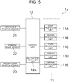
- control unit 12 is connected to each of four propulsion units 11 composed of the first propulsion unit 11A, the second propulsion unit 11B, the third propulsion unit 11C, and the fourth propulsion unit 11D.
- the control unit 12 controls each propulsion unit 11 to allow operation or stoppage of the propulsion unit 11.
- the control unit 12 is also connected to a first lever position sensor 21, a steering angle sensor 22, and a second lever position sensor 23.
- the first lever position sensor 21 detects the operating position of a throttle lever provided on the marine vessel 2.
- the control unit 12 adjusts the operating state of the driving source of the propulsion units 11 to change the rotational speed of the screw according to the operating position of the throttle lever operated by an operator (ship operator). This allows the propulsion units 11 to propel the marine vessel 2.
- the steering angle sensor 22 detects the steering angle of a steering wheel provided on the marine vessel 2.
- the second lever position sensor 23 detects the operating position of a steering lever provided on the marine vessel 2.
- the control unit 12 changes the rotation angle of the propulsion unit 11 (i.e., the rotary shaft direction of the screw) according to a manipulated variable of the steering wheel applied by the operator and/or the operating position of the second lever position sensor 23. This allows the propulsion units 11 to turn the marine vessel 2.
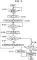
- FIG. 3 is a flowchart illustrating a process in which the control unit 12 controls the propulsion units 11 based on the output results from the malfunction detection unit 12a.
- the control unit 12 controls the four propulsion units 11 based on the output results from the malfunction detection unit 12a.
- the control unit 12 determines whether a malfunction has occurred in any propulsion unit 11 among the four propulsion units 11 (step S101). This determination is performed based on the detection results from the malfunction detection unit 12a. That is, when the malfunction detection unit 12a detects occurrence of a malfunction in any of the propulsion units 11, the control unit 12 recognizes that the particular propulsion unit 11 malfunctions.
- step S101 If it is determined that a malfunction has occurred in any of the four propulsion units 11 (step S101, Yes), the control unit 12 stops the malfunctioning propulsion unit 11 (step S102). On the other hand, if it is determined that no malfunction has occurred in the four propulsion units 11 (step S101, No), the process returns to step S101.
- the control unit 12 After stopping the malfunctioning propulsion unit 11, the control unit 12 then stops at least one propulsion unit 11 among the propulsion units 11 that are arranged on the side opposite the malfunctioning propulsion unit 11 that is arranged on either of the left side and right side of the hull 3 (step S103).
- the propulsion unit 11 to be stopped here is the propulsion unit 11 for which occurrence of a malfunction has not been detected (hereinafter, also referred to as normal propulsion unit 11).
- the control unit 12 stops the second propulsion unit 11B, and then stops at least one of the third propulsion unit 11C and the fourth propulsion unit 11D on the right side, which are the propulsion units 11 arranged on the other of the right and left sides in the hull 3.
- the propulsion unit 11 in a left-right symmetric relationship with the malfunctioning propulsion unit 11 is stopped.
- the control unit 12 stops the second propulsion unit 11B, and also stops the third propulsion unit 11C.
- the propulsion units 11 that continue to be operated are the first propulsion unit 11A and the fourth propulsion unit 11D.
- control unit 12 determines whether a malfunction has occurred in the other propulsion units 11 that maintain operation (step S104).
- step S104 If it is determined that a malfunction has occurred in any of the other propulsion units 11 (step S104, Yes), the control unit 12 stops the other propulsion unit 11 (step S105). As in the example described above, if it is determined that a malfunction has newly occurred in the fourth propulsion unit 11D with the second propulsion unit 11B and the third propulsion unit 11C being stopped, the control unit 12 stops operation of the fourth propulsion unit 11D. On the other hand, if it is determined that no malfunction has occurred in any of the other propulsion units 11 (step S104, No), the process returns to step S104.
- the control unit 12 determines whether there are two or more remaining propulsion units in operation 11 or whether there are less than two remaining propulsion units in operation 11 (i.e., normal propulsion units in which no malfunction has occurred) (step S106).
- the number of the propulsion units 11 is four.
- the number of the propulsion units 11 to be stopped is three out of four. Since the number of propulsion units 11 in operation is one, the control unit 12 necessarily determines in step S106 that there are less than two remaining propulsion units 11 in operation.
- step S106 determines whether there are less than two propulsion units 11 in operation. If it is determined that there are less than two propulsion units 11 in operation (step S106, No), the control unit 12 determines whether there is one propulsion unit 11 in operation (step S108). According to the example described above, at step S108, the number of propulsion units 11 in operation is one. Therefore, decision made in step S108 is Yes.
- step S109 the control unit 12 continues operation of the one propulsion unit 11 in operation.
- the first propulsion unit 11A which is positioned on the side laterally opposite the fourth propulsion unit 11D, should be stopped.
- stopping the only operating first propulsion unit 11A would make it impossible to navigate. Therefore, in this case, operation of the first propulsion unit 11A is controlled not to be stopped.
- the control unit 12 may resume operation of the normal propulsion unit 11 in stoppage.
- operation of the first propulsion unit 11A is continued at step S109, while operation of the third propulsion unit 11C, which is normal and which was stopped at step S105, is resumed.
- the normal propulsion unit 11 to resume operation is preferably one propulsion unit that is arranged on the side opposite the one propulsion unit 11 in operation that is arranged on either of the left side and right side of the hull 3.
- the number of the propulsion units 11 is four. Since operation of a total of three propulsion units 11 is stopped at S101 through step S105, decision made in step S106 is always No. However, when the number of the propulsion units 11 is five or more, decision made in step S106 may be Yes. In this case, as in step S103, the control unit 12 stops the propulsion unit 11 arranged on the side opposite the malfunctioning propulsion unit 11 (step S107). The process then returns to step S104.
- the number of the propulsion units 11 is an even number (four). Therefore, as a malfunction has occurred in any of the propulsion units 11 and the particular malfunctioning propulsion unit 11 is stopped together with the propulsion unit 11 corresponding thereto, the number of the propulsion units 11 that continue to be operated decreases while maintaining an even number, for example, as from four to two.
- the processing of step S109 described above is performed.
- the number of the propulsion units 11 is an odd number, for example, five.
- the number of the propulsion units 11 that continue to be operated decreases while maintaining an odd number, for example, as from five to three, or from three to one.
- the particular propulsion unit 11 is stopped in step S105. Since operation of all the propulsion units 11 has been stopped, decision made in step S106 is No and decision made in step S108 is also No.
- the control unit 12 then resumes operation of at least one normal propulsion unit 11 in stoppage (step S110).
- step S108 a state in which at least one normal propulsion unit 11 is operational is realized, and the propulsive force is then secured. This allows the marine vessel 2 to continue sailing.
- the marine vessel propulsion device 1 of the particular embodiment includes the four propulsion units 11, the malfunction detection unit 12a, and the control unit 12.
- the four propulsion units 11 are mounted to the hull 3 of the marine vessel 2.
- the malfunction detection unit 12a is capable of detecting occurrence of a malfunction for each of the four propulsion units 11.
- the control unit 12 controls the four propulsion units 11.
- the four propulsion units 11 are arranged left-right symmetrically.
- control unit 12 stops, among the four propulsion units 11, at least one propulsion unit 11 that is arranged on the side opposite the propulsion unit 11 for which occurrence of a malfunction has been detected and which is arranged on either of the left side and the right side of the hull 3.
- the at least one propulsion unit to be stopped with the stoppage of the propulsion unit 11 for which occurrence of a malfunction has been detected includes a propulsion unit 11 that is in a left-right symmetrical relationship with the propulsion unit 11 for which occurrence of a malfunction has been detected.
- the control unit 12 stops the another propulsion unit 11.
- the control unit 12 maintains operation of the propulsion unit 11 in operation.
- operation of the at least one propulsion unit 11 has been stopped without occurrence of a malfunction being detected may be resumed.
- the control unit 12 resumes operation of the propulsion unit 11 that has been stopped without occurrence of a malfunction being detected.
- the configuration of the marine vessel propulsion device 1 of the particular embodiment may be modified so that when the number of the propulsion units 11 in operation is reduced to one as a result of stopping the another propulsion unit 11 in which a malfunction have been newly detected, operation of the at least one propulsion unit 11 that has been stopped without occurrence of a malfunction being detected is resumed.
- the at least one propulsion unit 11 to be resumed includes the propulsion unit 11 that is arranged on the side opposite the propulsion unit 11 in operation that is arranged on either of the left side and right side of the hull 3.
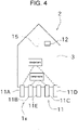
- FIG. 4 is a schematic plan view illustrating an overall configuration of a marine vessel 2 provided with the marine vessel propulsion device 1x according to the second embodiment.
- components that are identical or similar to those of the embodiment described above are designated with the same references in the drawings, and descriptions thereof may be omitted.
- the marine vessel propulsion device 1x illustrated in FIG. 4 is different from the marine vessel propulsion device 1 of the first embodiment, in terms of including an odd number of propulsion units (five propulsion units) 11.
- One propulsion unit 11 among the odd number of propulsion units 11 is arranged at the lateral center of the hull 3. This propulsion unit 11 arranged at the lateral center is controlled independently of the other propulsion units 11.
- the five propulsion units 11 are composed of a first propulsion unit 11A, a second propulsion unit 11B, a third propulsion unit 11C, a fourth propulsion unit 11D, and a central propulsion unit 11E.
- the five propulsion units 11 are arranged side-by-side along the left-right direction as in the first embodiment. Furthermore, the central propulsion unit 11E is arranged on the center line 15. Among the five propulsion units 11, the four propulsion units 11 except the central propulsion unit 11E are oppositely arranged on the right and left sides of the hull 3 across the central propulsion unit 11E.
- the first propulsion unit 11A and the second propulsion unit 11B are arranged on the left side in the hull 3.
- the third propulsion unit 11C and the fourth propulsion unit 11D are arranged on the right side in the hull 3.
- the first propulsion unit 11A and the fourth propulsion unit 11D are in a left-right symmetric corresponding relationship with respect to the center line 15, while the second propulsion unit 11B and the third propulsion unit 11C are in a left-right symmetric corresponding relationship with respect to the center line 15.
- the five propulsion units 11 are left-right symmetrical.
- the central propulsion unit 11E is connected to the control unit 12 to which the four other propulsion units 11 are connected.
- the control unit 12 controls the central propulsion unit 11E to allow operation or stoppage of the central propulsion unit 11E.
- the central propulsion unit 11E is controlled by the control unit 12 independently of the four other propulsion units 11. In other words, the central propulsion unit 11E is controlled regardless of the control status of the four other propulsion units 11.
- FIG. 6 is a flowchart illustrating a process in which the control unit 12 controls the central propulsion unit 11E based on the output results from the malfunction detection unit 12a.
- the control unit 12 controls the four propulsion units 11 except the central propulsion unit 11E among the five propulsion units 11, as in the first embodiment, based on the output results from the malfunction detection unit 12a.
- the control unit 12 also controls the central propulsion unit 11E while the central propulsion unit 11E is operated, independently of the control of the other propulsion units 11.
- the control unit 12 determines whether a malfunction has occurred in the central propulsion unit 11E (step S201). This determination is performed based on the detection results from the malfunction detection unit 12a. That is, when the malfunction detection unit 12a detects occurrence of a malfunction in the central propulsion unit 11E, the control unit 12 recognize that the central propulsion unit 11E malfunctions.
- step S201 if it is determined that no malfunction has occurred in the central propulsion unit 11E (step S201, No), the process returns to step S201.
- step S201 If it is determined that a malfunction has occurred in the central propulsion units 11E (step S201, Yes), the control unit 12 stops the central propulsion unit 11E (step S202).
- control unit 12 determines whether there is any propulsion unit 11 in operation (step S203). That is, it is determined, regarding the four other propulsion units 11, that whether there is any propulsion unit 11 that has not been stopped.
- step S203 If it is determined that there is some propulsion unit 11 in operation (step S203, Yes), the control unit 12 terminates the process. If it is determined that there is no propulsion unit 11 in operation (step S203, No), the control unit 12 resumes operation of the at least one normal propulsion unit 11 in stoppage (step S204) In this way, the propulsive force concerning the marine vessel 2 is surely ensured.
- the marine vessel propulsion device 1x of the particular embodiment includes an odd number of propulsion units (five propulsion units) 11.
- the central propulsion unit 11E which is one of the five propulsion units 11, is arranged at the lateral center of the hull 3.
- the control unit 12 controls the central propulsion unit 11E independently of the other propulsion units 11 among the five propulsion units 11.
- the central propulsion unit 11E is controllable. Therefore, it is possible to continue navigation while easily balancing the left and right propulsive forces by the other propulsion units 11. Furthermore, the strength of the propulsive force may be adjusted by the central propulsion unit 11E.
- the control unit 12 stops the central propulsion unit 11E when the malfunction detection unit 12a detects occurrence of a malfunction in the central propulsion units 11E.
- the control unit 12 resumes operation of the at least one normal propulsion unit 11 in stoppage.
- the number of the propulsion units 11 may be any number so long as it is three or more, and may be an even number or an odd number.
- the one propulsion unit 11 that is arranged at the lateral center of the hull 3 does not have to be controlled independently of the other propulsion units 11.
- a left-right symmetrical arrangement of three or more propulsion units 11 in the hull 3 includes not only a state in which one propulsion unit 11 is arranged at a position precisely left-right symmetrical with the other propulsion unit 11, but also a state in which one propulsion unit 11 is arranged at a position slightly displaced from the position precisely left-right symmetrical with the other propulsion unit 11.
- the marine vessel propulsion device 1 includes four propulsion units 11, and that the number of propulsion units 11 that continue to be operated is reduced, as in the example described above, from four to two, because a malfunction has occurred in any of the propulsion units 11. Then, consider a case in which a malfunction occurs in one of the two propulsion units 11 in operation, and in which there is only one remaining propulsion unit 11 in operation as a result of stopping the malfunctioning propulsion unit 11. In this case, in place of stopping both the malfunctioning propulsion unit 11 and the propulsion unit 11 in operation, the at least one normal propulsion unit 11 in stoppage may be resumed.
- the flowchart in Figure 3 is applicable to both a case in which there are an even number of propulsion units 11 and a case in which there are an odd number of the propulsion units 11.
- This flowchart may be modified to a flowchart specific to a case in which there are an even number of propulsion units 11 or a flowchart specific to a case in which there are an odd number of propulsion units 11.
Landscapes
- Chemical & Material Sciences (AREA)
- Engineering & Computer Science (AREA)
- Combustion & Propulsion (AREA)
- Mechanical Engineering (AREA)
- Ocean & Marine Engineering (AREA)
- Safety Devices In Control Systems (AREA)
- Control Of Position, Course, Altitude, Or Attitude Of Moving Bodies (AREA)
Applications Claiming Priority (2)
| Application Number | Priority Date | Filing Date | Title |
|---|---|---|---|
| JP2019215956A JP7348824B2 (ja) | 2019-11-29 | 2019-11-29 | 船舶用推進装置 |
| PCT/JP2020/038696 WO2021106401A1 (ja) | 2019-11-29 | 2020-10-14 | 船舶用推進装置 |
Publications (2)
| Publication Number | Publication Date |
|---|---|
| EP4067221A1 true EP4067221A1 (de) | 2022-10-05 |
| EP4067221A4 EP4067221A4 (de) | 2024-01-10 |
Family
ID=76086744
Family Applications (1)
| Application Number | Title | Priority Date | Filing Date |
|---|---|---|---|
| EP20891782.3A Withdrawn EP4067221A4 (de) | 2019-11-29 | 2020-10-14 | Schiffsantriebsvorrichtung |
Country Status (4)
| Country | Link |
|---|---|
| US (1) | US20220411031A1 (de) |
| EP (1) | EP4067221A4 (de) |
| JP (1) | JP7348824B2 (de) |
| WO (1) | WO2021106401A1 (de) |
Families Citing this family (6)
| Publication number | Priority date | Publication date | Assignee | Title |
|---|---|---|---|---|
| JP7501308B2 (ja) * | 2020-10-28 | 2024-06-18 | スズキ株式会社 | 船舶推進システム |
| JP2022090257A (ja) * | 2020-12-07 | 2022-06-17 | ヤマハ発動機株式会社 | 操船システムおよび船舶 |
| US12065230B1 (en) | 2022-02-15 | 2024-08-20 | Brunswick Corporation | Marine propulsion control system and method with rear and lateral marine drives |
| US12258115B2 (en) | 2022-07-20 | 2025-03-25 | Brunswick Corporation | Marine propulsion system and joystick control method |
| US12134454B1 (en) | 2022-07-20 | 2024-11-05 | Brunswick Corporation | Marine propulsion system and method with single rear drive and lateral marine drive |
| US12110088B1 (en) | 2022-07-20 | 2024-10-08 | Brunswick Corporation | Marine propulsion system and method with rear and lateral marine drives |
Family Cites Families (23)
| Publication number | Priority date | Publication date | Assignee | Title |
|---|---|---|---|---|
| JPH0613855B2 (ja) * | 1986-04-08 | 1994-02-23 | 三信工業株式会社 | 船舶用推進機の警告装置 |
| JP3089560B2 (ja) * | 1989-03-30 | 2000-09-18 | 三信工業株式会社 | 船舶推進機 |
| JP4707362B2 (ja) | 2003-10-22 | 2011-06-22 | ヤマハ発動機株式会社 | 推進力制御装置、それを備えた操船支援システムおよび船舶、ならびに推進力制御方法 |
| JP4680869B2 (ja) * | 2006-11-20 | 2011-05-11 | 本田技研工業株式会社 | 船外機の制御装置 |
| JP4895801B2 (ja) | 2006-12-28 | 2012-03-14 | ヤマハ発動機株式会社 | 推進機の制御装置 |
| JP5221244B2 (ja) * | 2008-08-22 | 2013-06-26 | ヤマハ発動機株式会社 | 船舶用電源システム、船舶用推進システムおよび船舶 |
| US8272906B2 (en) * | 2008-12-17 | 2012-09-25 | Yamaha Hatsudoki Kabushiki Kaisha | Outboard motor control device and marine vessel including the same |
| JP5102752B2 (ja) | 2008-12-17 | 2012-12-19 | ヤマハ発動機株式会社 | 船外機制御装置およびそれを備えた船舶 |
| JP5351611B2 (ja) * | 2009-05-29 | 2013-11-27 | ヤマハ発動機株式会社 | 船舶制御システム、船舶推進システムおよび船舶 |
| US8406944B2 (en) * | 2010-02-10 | 2013-03-26 | Pierre Garon | Control system and method for starting and stopping marine engines |
| JP2013163439A (ja) * | 2012-02-10 | 2013-08-22 | Yamaha Motor Co Ltd | 船外機の制御システム |
| JP2014080082A (ja) * | 2012-10-16 | 2014-05-08 | Yamaha Motor Co Ltd | 船舶用推進システムの運転方法、船舶用推進システムおよびそれを備えた船舶 |
| US9132903B1 (en) * | 2013-02-13 | 2015-09-15 | Brunswick Corporation | Systems and methods for laterally maneuvering marine vessels |
| JP2015229458A (ja) * | 2014-06-06 | 2015-12-21 | スズキ株式会社 | 船外機の識別番号設定装置及び識別番号設定方法 |
| JP6432903B2 (ja) * | 2014-09-26 | 2018-12-05 | 三菱重工業株式会社 | 垂直離着陸機、及び垂直離着陸機の制御方法 |
| US9764810B1 (en) * | 2015-06-23 | 2017-09-19 | Bruswick Corporation | Methods for positioning multiple trimmable marine propulsion devices on a marine vessel |
| US9598163B1 (en) * | 2016-01-22 | 2017-03-21 | Brunswick Corporation | System and method of steering a marine vessel having at least two marine drives |
| US10322787B2 (en) * | 2016-03-01 | 2019-06-18 | Brunswick Corporation | Marine vessel station keeping systems and methods |
| US10633072B1 (en) * | 2018-07-05 | 2020-04-28 | Brunswick Corporation | Methods for positioning marine vessels |
| JP2020101125A (ja) * | 2018-12-21 | 2020-07-02 | ヤマハ発動機株式会社 | 船舶推進機の制御装置およびそれを備えた船舶用推進システム、並びに船舶推進機のエンジン始動装置 |
| US11433981B2 (en) * | 2019-02-13 | 2022-09-06 | Marine Canada Acquisition Inc. | Electric actuator for a marine steering system, and methods of defining steering boundaries and determining drive mechanism failure thereof |
| US11312461B1 (en) * | 2019-10-29 | 2022-04-26 | Yamaha Hatsudoki Kabushiki Kaisha | Boat maneuvering control system for boat and boat maneuvering control method for boat |
| US11352118B1 (en) * | 2019-11-12 | 2022-06-07 | Brunswick Corporation | Marine propulsion control method and system |
-
2019
- 2019-11-29 JP JP2019215956A patent/JP7348824B2/ja active Active
-
2020
- 2020-10-14 US US17/780,918 patent/US20220411031A1/en not_active Abandoned
- 2020-10-14 WO PCT/JP2020/038696 patent/WO2021106401A1/ja not_active Ceased
- 2020-10-14 EP EP20891782.3A patent/EP4067221A4/de not_active Withdrawn
Also Published As
| Publication number | Publication date |
|---|---|
| JP2021084565A (ja) | 2021-06-03 |
| JP7348824B2 (ja) | 2023-09-21 |
| EP4067221A4 (de) | 2024-01-10 |
| US20220411031A1 (en) | 2022-12-29 |
| WO2021106401A1 (ja) | 2021-06-03 |
Similar Documents
| Publication | Publication Date | Title |
|---|---|---|
| EP4067221A1 (de) | Schiffsantriebsvorrichtung | |
| JP4331628B2 (ja) | 船舶推進装置の操舵装置および船舶 | |
| US9868501B1 (en) | Method and system for controlling propulsion of a marine vessel | |
| AU2012368885B2 (en) | Outboard motor control system | |
| EP2814727B1 (de) | Drehungs- und übersetzungssteuerungssystem für schiffe | |
| EP3406516B1 (de) | Schiffmanövriervorrichtung und schiff damit | |
| JP5102752B2 (ja) | 船外機制御装置およびそれを備えた船舶 | |
| EP3222511B1 (de) | Boot | |
| US11932370B1 (en) | Systems and methods for steering marine propulsion devices | |
| US20230069997A1 (en) | Electric driver device | |
| US11312461B1 (en) | Boat maneuvering control system for boat and boat maneuvering control method for boat | |
| JP5289485B2 (ja) | 多機掛け船舶推進機の制御装置 | |
| EP3434580B1 (de) | Schiff | |
| EP3434582B1 (de) | Schiff | |
| JP2008126773A (ja) | 船舶用操舵装置及び船舶 | |
| JP5132132B2 (ja) | 船舶用操舵装置及び船舶 | |
| JP4884504B2 (ja) | 船舶用操縦装置 | |
| JP6598307B2 (ja) | 少なくとも2つの船舶用ドライブを有する船舶の操舵システム及び操舵方法 | |
| US11685498B2 (en) | Ship maneuvering system | |
| US20250289556A1 (en) | Control system and ship |
Legal Events
| Date | Code | Title | Description |
|---|---|---|---|
| STAA | Information on the status of an ep patent application or granted ep patent |
Free format text: STATUS: THE INTERNATIONAL PUBLICATION HAS BEEN MADE |
|
| PUAI | Public reference made under article 153(3) epc to a published international application that has entered the european phase |
Free format text: ORIGINAL CODE: 0009012 |
|
| STAA | Information on the status of an ep patent application or granted ep patent |
Free format text: STATUS: REQUEST FOR EXAMINATION WAS MADE |
|
| 17P | Request for examination filed |
Effective date: 20220504 |
|
| AK | Designated contracting states |
Kind code of ref document: A1 Designated state(s): AL AT BE BG CH CY CZ DE DK EE ES FI FR GB GR HR HU IE IS IT LI LT LU LV MC MK MT NL NO PL PT RO RS SE SI SK SM TR |
|
| DAV | Request for validation of the european patent (deleted) | ||
| DAX | Request for extension of the european patent (deleted) | ||
| A4 | Supplementary search report drawn up and despatched |
Effective date: 20231207 |
|
| RIC1 | Information provided on ipc code assigned before grant |
Ipc: B63B 79/40 20200101ALI20231201BHEP Ipc: B63B 79/30 20200101ALI20231201BHEP Ipc: B63H 25/42 20060101ALI20231201BHEP Ipc: B63H 25/24 20060101ALI20231201BHEP Ipc: B63H 21/21 20060101ALI20231201BHEP Ipc: B63H 20/00 20060101AFI20231201BHEP |
|
| STAA | Information on the status of an ep patent application or granted ep patent |
Free format text: STATUS: THE APPLICATION HAS BEEN WITHDRAWN |
|
| 18W | Application withdrawn |
Effective date: 20240304 |